EP3479874A1 - Body insertable device having adjustable radiation emission direction - Google Patents
Body insertable device having adjustable radiation emission direction Download PDFInfo
- Publication number
- EP3479874A1 EP3479874A1 EP17820443.4A EP17820443A EP3479874A1 EP 3479874 A1 EP3479874 A1 EP 3479874A1 EP 17820443 A EP17820443 A EP 17820443A EP 3479874 A1 EP3479874 A1 EP 3479874A1
- Authority
- EP
- European Patent Office
- Prior art keywords
- outer body
- insertable device
- space
- accommodation space
- inner body
- Prior art date
- Legal status (The legal status is an assumption and is not a legal conclusion. Google has not performed a legal analysis and makes no representation as to the accuracy of the status listed.)
- Granted
Links
Images





Classifications
-
- A—HUMAN NECESSITIES
- A61—MEDICAL OR VETERINARY SCIENCE; HYGIENE
- A61N—ELECTROTHERAPY; MAGNETOTHERAPY; RADIATION THERAPY; ULTRASOUND THERAPY
- A61N5/00—Radiation therapy
- A61N5/10—X-ray therapy; Gamma-ray therapy; Particle-irradiation therapy
- A61N5/1001—X-ray therapy; Gamma-ray therapy; Particle-irradiation therapy using radiation sources introduced into or applied onto the body; brachytherapy
- A61N5/1007—Arrangements or means for the introduction of sources into the body
-
- A—HUMAN NECESSITIES
- A61—MEDICAL OR VETERINARY SCIENCE; HYGIENE
- A61N—ELECTROTHERAPY; MAGNETOTHERAPY; RADIATION THERAPY; ULTRASOUND THERAPY
- A61N5/00—Radiation therapy
- A61N5/10—X-ray therapy; Gamma-ray therapy; Particle-irradiation therapy
- A61N5/1001—X-ray therapy; Gamma-ray therapy; Particle-irradiation therapy using radiation sources introduced into or applied onto the body; brachytherapy
- A61N5/1014—Intracavitary radiation therapy
-
- A—HUMAN NECESSITIES
- A61—MEDICAL OR VETERINARY SCIENCE; HYGIENE
- A61N—ELECTROTHERAPY; MAGNETOTHERAPY; RADIATION THERAPY; ULTRASOUND THERAPY
- A61N5/00—Radiation therapy
- A61N5/10—X-ray therapy; Gamma-ray therapy; Particle-irradiation therapy
- A61N5/1001—X-ray therapy; Gamma-ray therapy; Particle-irradiation therapy using radiation sources introduced into or applied onto the body; brachytherapy
- A61N5/1014—Intracavitary radiation therapy
- A61N5/1016—Gynaecological radiation therapy
-
- A—HUMAN NECESSITIES
- A61—MEDICAL OR VETERINARY SCIENCE; HYGIENE
- A61N—ELECTROTHERAPY; MAGNETOTHERAPY; RADIATION THERAPY; ULTRASOUND THERAPY
- A61N5/00—Radiation therapy
- A61N5/10—X-ray therapy; Gamma-ray therapy; Particle-irradiation therapy
- A61N5/1001—X-ray therapy; Gamma-ray therapy; Particle-irradiation therapy using radiation sources introduced into or applied onto the body; brachytherapy
- A61N5/1002—Intraluminal radiation therapy
- A61N2005/1005—Intraluminal radiation therapy with asymmetrical radiation pattern
-
- A—HUMAN NECESSITIES
- A61—MEDICAL OR VETERINARY SCIENCE; HYGIENE
- A61N—ELECTROTHERAPY; MAGNETOTHERAPY; RADIATION THERAPY; ULTRASOUND THERAPY
- A61N5/00—Radiation therapy
- A61N5/10—X-ray therapy; Gamma-ray therapy; Particle-irradiation therapy
- A61N5/1001—X-ray therapy; Gamma-ray therapy; Particle-irradiation therapy using radiation sources introduced into or applied onto the body; brachytherapy
- A61N5/1007—Arrangements or means for the introduction of sources into the body
- A61N2005/1008—Apparatus for temporary insertion of sources, e.g. afterloaders
-
- A—HUMAN NECESSITIES
- A61—MEDICAL OR VETERINARY SCIENCE; HYGIENE
- A61N—ELECTROTHERAPY; MAGNETOTHERAPY; RADIATION THERAPY; ULTRASOUND THERAPY
- A61N5/00—Radiation therapy
- A61N5/10—X-ray therapy; Gamma-ray therapy; Particle-irradiation therapy
- A61N5/1001—X-ray therapy; Gamma-ray therapy; Particle-irradiation therapy using radiation sources introduced into or applied onto the body; brachytherapy
- A61N5/1014—Intracavitary radiation therapy
- A61N2005/1018—Intracavitary radiation therapy with multiple channels for guiding radioactive sources
-
- A—HUMAN NECESSITIES
- A61—MEDICAL OR VETERINARY SCIENCE; HYGIENE
- A61N—ELECTROTHERAPY; MAGNETOTHERAPY; RADIATION THERAPY; ULTRASOUND THERAPY
- A61N5/00—Radiation therapy
- A61N5/10—X-ray therapy; Gamma-ray therapy; Particle-irradiation therapy
- A61N2005/1092—Details
- A61N2005/1094—Shielding, protecting against radiation
Definitions
- an insertable device including: an outer body including a first outer body extending in a long manner, a second outer body extending in a long manner, and a bent part for connecting the first outer body and the second outer body such that the first outer body and the second outer body are bent; a first inner body positioned inside the first outer body, and having an accommodation space in which a radiation source is accommodated; a second inner body positioned inside the second outer body, having a guide space enabling the radiation source to pass therethrough, and being capable of operating the rotation thereof; and an inner connection part positioned in correspondence to the bent part inside the outer body, having a connection space communicating with a guide space and the accommodation space such that the radiation source is allowed to pass therethrough, and connecting the first inner body and the second inner body, wherein the first inner body is separated from the first outer body and rotated by the rotation of the second inner body.
- the accommodation space may be formed in a trench form within the first inner body.
- the inner connection part may include a rotation power mechanism.
- One end of the inner connection part may be fixed to the first inner body, and the other end of the inner connection part may be connected to the second inner body.
- the inner connection part and the outer body may be spaced from each other, such that the inner connection part rotates in correspondence to the outer body when the inner connection part is transformed in response to rotation of the second inner part.
- the cross-sectional area of the second guide space may increase in proportion to proximity to the connection space.
- the first inner body may be made of a material with excellent radiation shielding performance, compared to the first outer body.
- An angle of emission of radiation from the radiation source to an outside of the first outer body may be 5 degrees to 180 degrees.
- an insertable device including: an outer body being bent; and an inner body positioned inside the outer body, having an accommodation space in which the resource soured is accommodated, and being capable of rotating inside the outer body, wherein a radiation emission direction is continuously adjusted by rotation of the inner body.
- the inner body may include: a first inner body in which the accommodation space is formed; a second inner body having an operator capable of operating rotation; and a flexible shaft connecting the first inner body and the second inner body and being bent.
- an insertable device for brachytherapy which is bent and capable of adjusting radiation intensity.
- An insertable device 1 is largely comprised of an outer body 100 and an inner body 200.
- the outer body 100 defines an overall outer appearance of the insertable device 1, and accommodates the inner body 200 in an empty space therein. In this embodiment, an operator 222 in the inner body 200 is exposed to an outside of the outer body 100.
- the outer body 100 is in an overall thin and long shape and bent. Specifically, the outer body 100 includes a first outer body 110, a second outer body 120, and a bent part 130, and the first outer body 110 and the second body 120 are connected by the bent part 130 such that the first outer body and the second outer body are bent.
- Such an outer body 100 may be provided in various manners.
- the outer body 100 may be provided as an overall integrated body or may be provided as the first outer body 110 and the second outer body 120 are manufactured individually and coupled thereto by welding or the like.
- the outer body 100 may be in a form which is made such that the first outer body 110 and/or the second outer body 120 are manufactured as a plurality of parts and coupled to each other.
- Each of the first outer body 110 and the second outer body 120 may have a vertical cross section in a lengthwise direction, which is in a circular shape, and a cross section of an inner space of each of the first outer body 110 and the second outer body 120 is also in a circular shape. According to an orientation of the lengthwise direction, a cross-sectional area of each of the first outer body 110 and the second outer body 120, and a cross-sectional area of the inner space of each of the first outer body 110 and the second outer body 120 change. Overally, a cross-sectional area of the second outer body 120 is greater than a cross-sectional area of the first outer body 110. In another embodiment, a cross section of the first outer body 110 and/or the second outer body 120 may be in an elliptical shape rather than the circular shape.
- the second outer body 120 is inserted into a human body, and the other part is exposed to an outside.
- the second outer body 120 may be made of a metallic material such as stainless steel or a non-metallic material such as plastic.
- the inner body 200 includes a first inner body 210, a second inner body 220, an inner connection part 230, and a position limiting part 240.
- the first accommodation space 213a is formed in a trench form, and the second accommodation space 213b has a cross-sectional area expanded than a cross section of the first accommodation space 213a.
- the second accommodation space 213b has a funnel shape, of which a cross-sectional area increases in proportion to proximity to the inner connection part 230.
- the second inner body 220 is comprised of a first part 221 extending in a long manner, and a second part (an operator 222) extending in width.
- the operator 222 is exposed to an outside of an end of the outer body 100.
- a guide space 223 extending in a long manner along a lengthwise direction is formed in the second inner body 220.
- the guide space 223 includes a first guide space 223a and a second guide space 223b, and the second guide space 223b is formed at a portion adjacent to the inner connection part 230 and has a cross-sectional area greater than a cross-sectional area of the first guide space 223a.
- the second guide space 223b has a funnel shape, of which a cross-sectional area increases in proportion to proximity to the inner connection part 230.
- the brachytherapy may be performed effectively, and this is described with reference to FIGS. 6 to 9 .
- an insertion angle that is, an angle between the first outer body 110 and the second outer body 120
- the insertion angle may be adjusted and fixed outside a human body.
- Angle adjustment may be performed continuously or in stepwise, and a well-known configuration may be adapted for angle adjustment configuration.
Landscapes
- Health & Medical Sciences (AREA)
- Engineering & Computer Science (AREA)
- Biomedical Technology (AREA)
- Pathology (AREA)
- Nuclear Medicine, Radiotherapy & Molecular Imaging (AREA)
- Radiology & Medical Imaging (AREA)
- Life Sciences & Earth Sciences (AREA)
- Animal Behavior & Ethology (AREA)
- General Health & Medical Sciences (AREA)
- Public Health (AREA)
- Veterinary Medicine (AREA)
- Radiation-Therapy Devices (AREA)
Abstract
Description
- The present invention relates to an insertable device and, more particularly, to a body insertable device for brachytherapy.
- Radiation therapy for cancer patients may be classified largely into two types: external beam radiation therapy where radiation is delivered to a tumor from a radiation source placed outside a patient's body, and brachytherapy where radiation is delivered from a radiation source placed inside a patient's body.
- Among them, the brachytherapy is carried out by inserting the radiation source into a tumor and delivering a high radiation dose to the tumor, and there is an advantage that the radiation dose transmitted to surrounding healthy organs may be reduced significantly.
- In the brachytherapy, radiation is emitted by moving the radiation source through an insertable device inserted into a human body, but there is a problem that a technology for adjusting three-dimensional radiation intensity using the insertable device by adjusting a radiation direction has not been developed enough.
- In particular, when a bent insertable device needs to be used to emit radiation to a tumor which is located like uterine cancer, it is difficult to assign an intensity adjusting function to the insertable device.
- An object of the present invention is to provide an insertable device for brachytherapy, the device which is bent and capable of adjusting radiation intensity.
- The above objects of the present invention can be achieved by an insertable device including: an outer body including a first outer body extending in a long manner, a second outer body extending in a long manner, and a bent part for connecting the first outer body and the second outer body such that the first outer body and the second outer body are bent; a first inner body positioned inside the first outer body, and having an accommodation space in which a radiation source is accommodated; a second inner body positioned inside the second outer body, having a guide space enabling the radiation source to pass therethrough, and being capable of operating the rotation thereof; and an inner connection part positioned in correspondence to the bent part inside the outer body, having a connection space communicating with a guide space and the accommodation space such that the radiation source is allowed to pass therethrough, and connecting the first inner body and the second inner body, wherein the first inner body is separated from the first outer body and rotated by the rotation of the second inner body.
- The accommodation space may be formed to extending in a long manner along the first inner body.
- The accommodation space may be formed in a trench form within the first inner body.
- The insertable device may further include a position limiting part positioned close to the first outer body within the accommodation space and limiting a position of the radiation resource.
- A vertical cross section of the first inner body in a lengthwise direction may be in a circular shape, and the accommodation space may accommodate the radiation source at an eccentric position.
- The inner connection part may include a rotation power mechanism.
- The rotation power mechanism may include at least one of a flexible shaft, a bellows, or a joint.
- One end of the inner connection part may be fixed to the first inner body, and the other end of the inner connection part may be connected to the second inner body.
- The inner connection part and the outer body may be spaced from each other, such that the inner connection part rotates in correspondence to the outer body when the inner connection part is transformed in response to rotation of the second inner part.
- The accommodation space may include: a first accommodation space; and a second accommodation space positioned between the first accommodation space and the connection space, and the second accommodation space may have a cross-sectional area greater than a cross-sectional area of the first accommodation space.
- The cross-sectional area of the second accommodation space may increase in proportion to proximity to the connection space.
- The guide space may include: a first guide space; and a second guide space positioned between the first guide space and the connection space, and the second guide space may have a cross-sectional area greater than a cross-sectional area of the first guide space.
- The cross-sectional area of the second guide space may increase in proportion to proximity to the connection space.
- The first inner body may be made of a material with excellent radiation shielding performance, compared to the first outer body.
- An angle of emission of radiation from the radiation source to an outside of the first outer body may be 5 degrees to 180 degrees.
- The above objects of the present invention can be achieved by an insertable device including: an outer body being bent; and an inner body positioned inside the outer body, having an accommodation space in which the resource soured is accommodated, and being capable of rotating inside the outer body, wherein a radiation emission direction is continuously adjusted by rotation of the inner body.
- The inner body may include: a first inner body in which the accommodation space is formed; a second inner body having an operator capable of operating rotation; and a flexible shaft connecting the first inner body and the second inner body and being bent.
- According to the present invention, there is provided an insertable device for brachytherapy, which is bent and capable of adjusting radiation intensity.
-
-
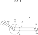
FIG. 1 is a perspective view of an insertable device according to an embodiment of the present invention. -
FIG. 2 is an exploded perspective view of an insertable device according to an embodiment of the present invention. -
FIG. 3 illustrates inner configurations of a portion A ofFIG. 1 . -
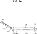
FIGS. 4A and4B illustrate a change in a position of an accommodation space in which a radiation source is accommodated in an insertable device according to an embodiment of the present invention. -
FIG. 5 illustrates a cross-sectional view taken along line V-V' ofFIG. 1 . -
FIGS. 6 and7 illustrate adjustment of a radiation direction in an insertable device according to the present invention. -
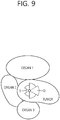
FIGS. 8 and9 are for explanation of cancer treatment using an insertable device according to the present invention. -
FIG. 10 illustrates an exemplary variation of an insertable device according to the present invention. - Hereinafter, the present invention will be described in detail with reference to the accompanying drawings.
- The accompanying drawings are only examples shown in order to describe the technical spirit of the present invention in more detail. Therefore, the technical spirit of the present invention is not limited to shapes of the accompanying drawings.
- An insertable device according to an embodiment of the present invention is described with reference to
FIGS. 1 to 5 . -
FIG. 1 is a perspective view of an insertable device according to an embodiment of the present invention,FIG. 2 is an exploded perspective view of an insertable device according to an embodiment of the present invention,FIG. 3 illustrates inner configurations of a portion A ofFIG. 1 ,FIGS. 4A and4B illustrate a change in a position of an accommodation space in which a radiation source is accommodated in an insertable device according to an embodiment of the present invention,FIG. 5 illustrates a cross-sectional view taken along line V-V' ofFIG. 1 .FIG. 2 illustrates a perspective view of a cross section in a lengthwise direction. - An
insertable device 1 according to an embodiment of the present invention is largely comprised of anouter body 100 and aninner body 200. - The
outer body 100 defines an overall outer appearance of theinsertable device 1, and accommodates theinner body 200 in an empty space therein. In this embodiment, anoperator 222 in theinner body 200 is exposed to an outside of theouter body 100. - The
outer body 100 is in an overall thin and long shape and bent. Specifically, theouter body 100 includes a firstouter body 110, a secondouter body 120, and abent part 130, and the firstouter body 110 and thesecond body 120 are connected by thebent part 130 such that the first outer body and the second outer body are bent. - Such an
outer body 100 may be provided in various manners. Theouter body 100 may be provided as an overall integrated body or may be provided as the firstouter body 110 and the secondouter body 120 are manufactured individually and coupled thereto by welding or the like. In addition, theouter body 100 may be in a form which is made such that the firstouter body 110 and/or the secondouter body 120 are manufactured as a plurality of parts and coupled to each other. - Each of the first
outer body 110 and the secondouter body 120 may have a vertical cross section in a lengthwise direction, which is in a circular shape, and a cross section of an inner space of each of the firstouter body 110 and the secondouter body 120 is also in a circular shape. According to an orientation of the lengthwise direction, a cross-sectional area of each of the firstouter body 110 and the secondouter body 120, and a cross-sectional area of the inner space of each of the firstouter body 110 and the secondouter body 120 change. Overally, a cross-sectional area of the secondouter body 120 is greater than a cross-sectional area of the firstouter body 110. In another embodiment, a cross section of the firstouter body 110 and/or the secondouter body 120 may be in an elliptical shape rather than the circular shape. - The first
outer body 110 of theouter body 100 is primarily brought into contact or close to a treatment target (tumor or the like), and, while the firstouter body 110 is brought into contact or close to the treatment target, radiation is emitted toward the treatment target from a radiation source placed inside theinner body 200. The firstouter body 110 may be made of a metallic material with a low atomic number such as titanium or a non-metallic material such as plastic. - Part of the second
outer body 120 is inserted into a human body, and the other part is exposed to an outside. The secondouter body 120 may be made of a metallic material such as stainless steel or a non-metallic material such as plastic. - The
inner body 200 includes a firstinner body 210, a secondinner body 220, aninner connection part 230, and aposition limiting part 240. - The first
inner body 210 includes afirst part 211 extending in a long manner, and asecond part 212 extending in width. - An
accommodation space 213 extending in a long manner along a lengthwise direction is formed in the firstinner body 210. Theaccommodation space 213 includes afirst accommodation space 213a formed in thefirst part 211, and asecond accommodation space 213b formed in thesecond part 212. - The
first accommodation space 213a is formed in a trench form, and thesecond accommodation space 213b has a cross-sectional area expanded than a cross section of thefirst accommodation space 213a. Specifically, thesecond accommodation space 213b has a funnel shape, of which a cross-sectional area increases in proportion to proximity to theinner connection part 230. - The second
inner body 220 is comprised of afirst part 221 extending in a long manner, and a second part (an operator 222) extending in width. Theoperator 222 is exposed to an outside of an end of theouter body 100. - A
guide space 223 extending in a long manner along a lengthwise direction is formed in the secondinner body 220. Theguide space 223 includes afirst guide space 223a and asecond guide space 223b, and thesecond guide space 223b is formed at a portion adjacent to theinner connection part 230 and has a cross-sectional area greater than a cross-sectional area of thefirst guide space 223a. Specifically, thesecond guide space 223b has a funnel shape, of which a cross-sectional area increases in proportion to proximity to theinner connection part 230. - Meanwhile, a
third part 224 is provided on an outside of thesecond part 222. Thethird part 224 serves to connect an external radiation source to theguide space 223. - The
inner connection part 230 is provided at a portion corresponding to abent part 130 of theouter body 100, and has aconnection space 231 therein. One end of theinner connection part 230 is coupled to the firstinner body 210, and the other part of theinner connection part 230 is coupled to the secondinner body 220 and bent in correspondence to thebent part 130. Connection of theinner connection part 230 and theinner body - The
inner connection part 230 is, but not limited to, a rotation power transmitting mechanism between two shafts that intersect each other and may be at least one of a flexible shaft, a bellows, or a joint. In particular, theinner connection part 230 may be a pipe-shaped flexible shaft and may be especially made of a high-carbon steel wire. In the present invention, theinner connection part 230 may have various shapes as long as theinner connection part 230 maintains an accommodation space therein and transmits rotating motion of the secondinner body 220 to the firstinner body 210 while corresponding to a shape of theouter body 100. - The
position limiting part 240 is in a thin and long shape, and positioned at the periphery of thefirst accommodation space 213a. A radiation source is positioned in an empty space under theposition limiting part 240 of thefirst accommodation space 213a (that is, a portion close to the center of the first inner body 210). That is, with the radiation source being inserted, the firstouter body 110, theposition limiting part 240, and the radiation source are arranged in order. - The second part (the operator 222) is exposed to an outside, and a user rotates the
operator 222 to change an emission direction and adjust radiation intensity. - Insertion of the radiation source in the above-described
insertable device 1 will be described. - The radiation source is connected to an end of a thin and long wire, which is provided close to an external brachytherapy device, and emits radiation.
- The radiation source passes through the
guide space 223 formed within the secondinner body 220 and through theconnection space 231 formed within theinner connection part 230, and is then finally positioned within theaccommodation space 213 formed in the firstinner body 210. A position of the radiation source in a lengthwise direction in theaccommodation space 213 may be adjusted in various ways. - In a path of insertion of the radiation source, both ends of the
connection space 231 with a diameter greater than a diameter of thefirst guide space 223a and a diameter of thefirst accommodation space 213a are connected to each other by the funnel-shapedsecond guide space 223b and the funnel-shapedsecond accommodation space 213b. Due to this structure, theguide space 223, theconnection space 231, and theaccommodation space 213 form a continuous structure without a step formed therein, so that the radiation resource is prevented from being stopped by theinner body 200 when being inserted, and the insertion of the radiation source is stably guided. - In addition, the radiation source is prevented from being stopped by the
inner body 200 during the process of recovering the radiation source, and removal of the radiation source may be stably guided. - In another embodiment, an additional guide pipe may be used for stable insertion and recovery of the radiation source. In this case, the guide pipe may be provided over the entire length of the
inner body 200 or may be provided only in theconnection space 231. - Hereinafter, adjustment of radiation intensity in response to adjustment of an emission direction of the inserted radiation source is described.
- In
FIG. 4A , the radiation source is inserted in an upward direction. In this state, if theoperator 222 is rotated in the outside, the secondinner body 220 is rotated with theouter body 100 being fixed. If the secondinner body 220 is rotated, theinner connection part 230 connected thereto is transformed and thus rotated. In this case, an empty space B is formed between theinner connection part 230 and theouter body 100, as shown inFIG. 3 , and thus, interference with theouter body 100 does not happen despite transformation of theinner connection part 230. - Meanwhile, in another embodiment, an inner connection part 300 is in contact with the
outer body 100 or brought into contact with theouter body 100 when being rotated. In this case, the inner connector 300 may be rotated while being transformed in correspondence to an inner shape of theouter body 100. - If the
inner connector part 230 is rotated, the firstinner body 210 connected thereto is also rotated, and thus, the position of the accommodation space for the radiation source is changed to face a downward direction, as shown inFIG. 4B . In response to the change in the position of the radiation source, a radiation emission direction is changed. - Overally, the radiation emission direction is changed in response to rotation of the
operator 222, and a degree of change in the radiation emission direction may be 10% to 100%, 30% to 100%, 50% to 100%, and 80% to 100% of a degree of rotation of theoperator 222. In response to the rotation of theoperator 222, the radiation emission direction may be rotated by the same angle of the rotation of theoperator 222. - Configurations of the
operator 222 may be changed in various ways. An additional device may be further included to reduce a degree of change in the radiation emission direction in response to a different degree of rotation. In another embodiment, theoperator 222 may not be integrally formed with the secondinner body 220, or may rotate the secondinner body 220 through an additional configuration connected to the secondinner body 220 without having theoperator 222 in the secondinner body 220. In yet another embodiment, the secondinner body 220 may be rotated through an additional mechanical-electric device. - The emission direction of the radiation source is changed in the above process, and this will be described in more detail with reference to
FIG. 5 . -
FIG. 5 illustrates the case where the radiation source is in theaccommodation space 213 of the firstinner body 210. Theaccommodation space 213 is in a trench shape and faces the firstouter body 110. - The
position limiting part 240 is positioned in an upper space of theaccommodation space 213, that is, a space directly facing the firstouter body 110. The position of the radiation source is limited to the inside of theaccommodation space 213 by theposition limiting part 240. Thus, the radiation source is positioned at a predetermined distance from an outer surface (a circumferential surface) of the firstinner body 210, and the distance to the outer surface is maintained constantly by theposition limiting part 240. - In this arrangement, the radiation source is not positioned at the center of the first
inner body 210 but is positioned eccentrically from the center thereof. The firstinner body 210 is made of a material with excellent radiation shielding performance compared to the firstouter body 110, and, for example, the firstinner body 210 may be made of tungsten or tungsten alloy. Since the firstinner body 210 has a very small diameter, it is hard to completely shield radiation in an undesired direction. According to this embodiment, the radiation source is positioned eccentrically, and thus, the firstinner body 210 in a direction (a direction C inFIG. 5 ) in which emission of radiation from the radiation source is not desired may have a relatively great thickness. Thus, it is possible to minimize emission of radiation in an undesired direction. - The
position limiting part 240 may be made of a polymer material, and, for smooth rotation of the firstinner body 210, the firstinner body 210 and the firstouter body 110 may be spaced apart from each other and a lubricating film may be formed therebetween. - Using the insertable device according to the present invention, the brachytherapy may be performed effectively, and this is described with reference to
FIGS. 6 to 9 . - First, it is possible to effectively limit a radiation emission angle according to the present invention. Radiation is evenly emitted in a direction of 360 degrees from the radiation source. According to the present invention, as illustrated in
FIG. 5 , the radiation source is spaced from the circumferential surface of the firstinner body 210. Thus, an emission angle (Θ inFIG. 6 ) of emission of radiation from the radiation source is limited by the firstinner body 210. The emission angle is determined depending on a distance between the radiation resource and the circumferential surface of the firstinner body 210, a size of theaccommodation space 213, and a shape of theaccommodation space 213. The radiation emission angle may be 5 degrees to 180 degrees, 5 degrees to 120 degrees, 5 degrees to 60 degrees, 5 degrees to 30 degrees, 10 degrees to 120 degrees, 10 degrees to 60 degrees, 10 degrees to 30 degrees, 30 degrees to 120 degrees, 30 degrees to 90 degrees, or 30 degrees to 60 degrees. - In addition, according to the present invention, the radiation direction may be adjusted continuously. That is, depending on a degree of rotation, the position of the radiation source may be changed, not in phases, but continuously. Thus, radiation may be emitted in a desired direction, as shown in
FIG. 7 . - With reference to
FIGS. 8 and9 , treatment of uterine cancer using the insertable device according to the present invention will be described. - The
insertable device 1 is inserted into a human body and then the radiation source is introduced into theinsertable device 1. When the insertion is completed, the right side at a position "C" inFIG. 8 is exposed to an outside of the human body. In addition, the firstouter body 110 is inserted into a position of a tumor in accordance with a bent structure of theinsertable device 1 inside the human body. In another embodiment, after the radiation source is introduced into theinsertable device 1, theinsertable device 1 may be inserted into the human body. - In this state, based on a shape and a position of a tumor found in a previous medical examination, the medical profession adjusts a position and a radiation direction of the radiation source according to a lengthwise direction of the first
outer body 110. The radiation direction of the radiation source is adjusted by adjusting the operator, as described above. - When the position of the radiation source is determined with respect to a tumor shape as shown in
FIG. 9 , emission time is increased in a direction toward D where many tumors exist, so that sufficient radiation is emitted. On the other hand, emission time is reduced in a direction toward E where few tumors exist, so that emission of radiation toward surrounding organs is minimized. - During this treatment process, a radiation emission direction may be easily adjusted using the
insertable device 1 of the present invention, and the radiation source may be easily inserted and removed. - In the above description, treatment of uterine cancer is exemplified, but the insertable device of the present invention is not limited thereto and is applicable even to head and neck cancer, esophageal cancer, rectal cancer, and the like.
-
FIG. 10 illustrates a variation of an insertable device according to the present invention. - In an exemplary variation, the
accommodation space 213 is formed to be widen in proportion to distance from the radiation source. Formation of theaccommodation space 213 may be changed in various ways. Alternatively, theaccommodation space 213 may be formed such that the radiation source is positioned at the center of the firstinner body 210. - In another variation, an insertion angle, that is, an angle between the first
outer body 110 and the secondouter body 120, may be adjusted. The insertion angle may be adjusted and fixed outside a human body. Angle adjustment may be performed continuously or in stepwise, and a well-known configuration may be adapted for angle adjustment configuration. - In yet another variation, the
inner connection part 230 is integrally formed with at least one of the firstinner body 210 or the secondinner body 220. - The above embodiments are illustrative purpose only for the present invention and an exemplary embodiment of the present invention not limited thereto. Since numerous variations and modifications will become apparent to those skilled in the art once the above disclosure is fully appreciated, the scope and spirit of the invention come within the scope of the appended claims and their equivalents.
Claims (17)
- An insertable device comprising:an outer body including a first outer body extending in a long manner, a second outer body extending in a long manner, and a bent part for connecting the first outer body and the second outer body such that the first outer body and the second outer body are bent;a first inner body positioned inside the first outer body, and having an accommodation space in which a radiation source is accommodated;a second inner body positioned inside the second outer body, having a guide space enabling the radiation source to pass therethrough, and being capable of operating the rotation thereof; andan inner connection part positioned in correspondence to the bent part inside the outer body, having a connection space communicating with a guide space and the accommodation space such that the radiation source is allowed to pass therethrough, and connecting the first inner body and the second inner body,wherein the first inner body is separated from the first outer body and rotated by the rotation of the second inner body.
- The insertable device of claim 1, wherein the accommodation space is formed to extending in a long manner along the first inner body.
- The insertable device of claim 2, wherein the accommodation space is formed in a trench form within the first inner body.
- The insertable device of claim 3, further comprising a position limiting part positioned close to the first outer body within the accommodation space and limiting a position of the radiation resource.
- The insertable device of claim any one of claims 2 to 4,
wherein a vertical cross section of the first inner body in a lengthwise direction is in a circular shape, and
wherein the accommodation space accommodates the radiation source at an eccentric position. - The insertable device of any one of claims 2 to 4, wherein the inner connection part comprises a rotation power mechanism.
- The insertable device of claim 6, wherein the rotation power mechanism comprises at least one of a flexible shaft, a bellows, or a joint.
- The insertable device of claim 7, wherein one end of the inner connection part is fixed to the first inner body, and the other end of the inner connection part is connected to the second inner body.
- The insertable device of claim 7, wherein the inner connection part and the outer body are spaced from each other, such that the inner connection part rotates in correspondence to the outer body when the inner connection part is transformed in response to rotation of the second inner part.
- The insertable device of any one of claims 2 to 4,
wherein the accommodation space comprises:a first accommodation space; anda second accommodation space positioned between the first accommodation space and the connection space, andwherein the second accommodation space has a cross-sectional area greater than a cross-sectional area of the first accommodation space. - The insertable device of claim 10, wherein the cross-sectional area of the second accommodation space increases in proportion to proximity to the connection space.
- The insertable device of any one of claims 2 to 4,
wherein the guide space comprises:a first guide space; anda second guide space positioned between the first guide space and the connection space, andwherein the second guide space has a cross-sectional area greater than a cross-sectional area of the first guide space. - The insertable device of claim 12, wherein the cross-sectional area of the second guide space increases in proportion to proximity to the connection space.
- The insertable device of any one of claims 2 to 4, wherein the first inner body is made of a material with excellent radiation shielding performance, compared to the first outer body.
- The insertable device of any one of claims 2 to 4, wherein an angle of emission of radiation from the radiation source to an outside of the first outer body is 5 degrees to 180 degrees.
- An insertable device comprising:an outer body being bent; andan inner body positioned inside the outer body, having an accommodation space in which the resource soured is accommodated, and being capable of rotating inside the outer body,wherein a radiation emission direction is continuously adjusted by rotation of the inner body.
- The insertable device of claim 16, wherein the inner body comprises:a first inner body in which the accommodation space is formed;a second inner body having an operator capable of operating rotation; anda flexible shaft connecting the first inner body and the second inner body and being bent.
Applications Claiming Priority (2)
| Application Number | Priority Date | Filing Date | Title |
|---|---|---|---|
| KR1020160083434A KR101794128B1 (en) | 2016-07-01 | 2016-07-01 | Apparatus for body- inserting having controllable radiation direction |
| PCT/KR2017/006381 WO2018004166A1 (en) | 2016-07-01 | 2017-06-19 | Body insertable device having adjustable radiation emission direction |
Publications (3)
| Publication Number | Publication Date |
|---|---|
| EP3479874A1 true EP3479874A1 (en) | 2019-05-08 |
| EP3479874A4 EP3479874A4 (en) | 2020-03-11 |
| EP3479874B1 EP3479874B1 (en) | 2020-12-30 |
Family
ID=60787207
Family Applications (1)
| Application Number | Title | Priority Date | Filing Date |
|---|---|---|---|
| EP17820443.4A Active EP3479874B1 (en) | 2016-07-01 | 2017-06-19 | Body insertable device having adjustable radiation emission direction |
Country Status (6)
| Country | Link |
|---|---|
| US (1) | US11052263B2 (en) |
| EP (1) | EP3479874B1 (en) |
| JP (1) | JP6706356B2 (en) |
| KR (1) | KR101794128B1 (en) |
| CN (1) | CN109414593B (en) |
| WO (1) | WO2018004166A1 (en) |
Families Citing this family (6)
| Publication number | Priority date | Publication date | Assignee | Title |
|---|---|---|---|---|
| EP3335763A1 (en) * | 2016-12-16 | 2018-06-20 | Universiteit Maastricht | Endorectal probe device for effecting radiation treatment of colorectal cancerous tissue in the rectum of a human or animal subject |
| KR101951567B1 (en) * | 2017-10-24 | 2019-02-22 | 국립암센터 | Apparatus for body-inserting having controllable direction and shape of radiation |
| KR102068755B1 (en) * | 2018-06-05 | 2020-01-21 | 재단법인 아산사회복지재단 | Device, method and program for providing the plan of brachytherapy, and brachytherapy apparatus |
| US12318629B2 (en) * | 2019-06-13 | 2025-06-03 | The Royal Institution For The Advancement Of Learning/Mcgill University | Radiation shields for brachytherapy |
| CN112755409B (en) * | 2021-01-14 | 2023-01-17 | 陕西省肿瘤医院 | A radioactive iodine particle-protected gastric tube for the treatment of esophageal tumors |
| CN119015616B (en) * | 2024-08-14 | 2025-06-06 | 中国医学科学院北京协和医院 | Multichannel conversion X-ray source applicator |
Family Cites Families (15)
| Publication number | Priority date | Publication date | Assignee | Title |
|---|---|---|---|---|
| US3060924A (en) | 1960-06-01 | 1962-10-30 | Joseph C Rush | Apparatus for application of radioactive substance to pelvic cancer |
| JP2001190700A (en) | 1999-12-30 | 2001-07-17 | Radi Medical Technologies Ab | Apparatus for controlling x-ray dose |
| US6540655B1 (en) * | 2000-11-10 | 2003-04-01 | Scimed Life Systems, Inc. | Miniature x-ray unit |
| US7744520B2 (en) | 2004-02-12 | 2010-06-29 | Neovista, Inc. | Method and apparatus for intraocular brachytherapy |
| KR200394440Y1 (en) * | 2005-04-28 | 2005-09-01 | 중앙검사 주식회사 | source guide tube device for a radioactive ray irradiation equipment |
| US8273006B2 (en) * | 2005-11-18 | 2012-09-25 | Senorx, Inc. | Tissue irradiation |
| US7686755B2 (en) * | 2006-06-19 | 2010-03-30 | Xoft, Inc. | Radiation therapy apparatus with selective shielding capability |
| NL1035971C (en) | 2008-09-23 | 2010-03-24 | Nucletron Bv | Assembly for performing brachytherapy treatment of tumour tissue in an animal body. |
| EP2239005B1 (en) | 2009-04-01 | 2012-11-14 | Nucletron Operations B.V. | Components and assembly for performing brachytherapy treatment of tumor tissue in an human and animal body |
| US8808156B1 (en) * | 2009-04-01 | 2014-08-19 | Loren Godfrey, Jr. | Minimally invasive applicator for intraoperative radiotherapy |
| DE102009058777A1 (en) | 2009-12-18 | 2011-06-22 | Carl Zeiss Surgical GmbH, 73447 | Applicator device for radiotherapy and radiotherapy device |
| DE102012002466B4 (en) * | 2012-02-08 | 2014-05-08 | Carl Zeiss Meditec Ag | Angled applicator for radiotherapy |
| US8979725B2 (en) * | 2012-05-23 | 2015-03-17 | Mark A. D'Andrea | Brachytherapy tandem and ovoid implantation devices and methods |
| WO2014021947A1 (en) | 2012-07-31 | 2014-02-06 | University Of Iowa Research Foundation | Advanced rotating-shield brachytherapy and planning of the same |
| CN204734852U (en) * | 2015-05-21 | 2015-11-04 | 山东新华医疗器械股份有限公司 | Source ware is executed to cervical |
-
2016
- 2016-07-01 KR KR1020160083434A patent/KR101794128B1/en active Active
-
2017
- 2017-06-19 JP JP2018569020A patent/JP6706356B2/en active Active
- 2017-06-19 WO PCT/KR2017/006381 patent/WO2018004166A1/en not_active Ceased
- 2017-06-19 US US16/312,788 patent/US11052263B2/en active Active
- 2017-06-19 EP EP17820443.4A patent/EP3479874B1/en active Active
- 2017-06-19 CN CN201780040257.1A patent/CN109414593B/en active Active
Also Published As
| Publication number | Publication date |
|---|---|
| KR101794128B1 (en) | 2017-11-30 |
| JP2019520155A (en) | 2019-07-18 |
| CN109414593B (en) | 2020-11-13 |
| WO2018004166A1 (en) | 2018-01-04 |
| US11052263B2 (en) | 2021-07-06 |
| EP3479874B1 (en) | 2020-12-30 |
| JP6706356B2 (en) | 2020-06-03 |
| US20190329066A1 (en) | 2019-10-31 |
| EP3479874A4 (en) | 2020-03-11 |
| CN109414593A (en) | 2019-03-01 |
Similar Documents
| Publication | Publication Date | Title |
|---|---|---|
| EP3479874B1 (en) | Body insertable device having adjustable radiation emission direction | |
| US10286114B2 (en) | Device and method for targeted radiation therapy | |
| US9132282B2 (en) | Brachytherapy applicator device for insertion in a body cavity | |
| JP5213851B2 (en) | Expandable brachytherapy device | |
| US20080214887A1 (en) | Brachytherapy apparatus and method using off-center radiation source | |
| CN216417288U (en) | Flexible Needle Puncture Device | |
| JP2019162416A (en) | Variable pitch flexible needle | |
| US10307567B2 (en) | Catheter and methods related thereto | |
| US11471701B2 (en) | Body-insertable device having adjustable radiation emission direction and radiation emission range | |
| CN111671504A (en) | A multifunctional trocar for distributed particle implantation and biopsy | |
| KR20190031732A (en) | Probe bracket and needle guide for ultrasonic system | |
| CN111655322B (en) | Catheter handle and catheter with same | |
| CN109791810B (en) | Radiation delivery devices and their applications | |
| CN116096462A (en) | Radiation Therapy Reference Locator | |
| CN117017445B (en) | A rapid implantation device and system for radioactive particles | |
| CN221105970U (en) | Quick implantation device and system for radioactive particles | |
| WO2014059041A1 (en) | Device and method for targeted radiation therapy | |
| JP2001245897A (en) | High frequency incision device | |
| US20090112046A1 (en) | Brachytherapy Apparatus and Method Using Rotating Radiation Source | |
| KR20180024963A (en) | The strengthening thin-needle for visibility of ultrasound biopsy induction video | |
| CN121646489A (en) | Slit needles used in radiotherapy | |
| JP2015008745A (en) | Insert system and insert |
Legal Events
| Date | Code | Title | Description |
|---|---|---|---|
| STAA | Information on the status of an ep patent application or granted ep patent |
Free format text: STATUS: THE INTERNATIONAL PUBLICATION HAS BEEN MADE |
|
| PUAI | Public reference made under article 153(3) epc to a published international application that has entered the european phase |
Free format text: ORIGINAL CODE: 0009012 |
|
| STAA | Information on the status of an ep patent application or granted ep patent |
Free format text: STATUS: REQUEST FOR EXAMINATION WAS MADE |
|
| 17P | Request for examination filed |
Effective date: 20181219 |
|
| AK | Designated contracting states |
Kind code of ref document: A1 Designated state(s): AL AT BE BG CH CY CZ DE DK EE ES FI FR GB GR HR HU IE IS IT LI LT LU LV MC MK MT NL NO PL PT RO RS SE SI SK SM TR |
|
| AX | Request for extension of the european patent |
Extension state: BA ME |
|
| DAV | Request for validation of the european patent (deleted) | ||
| DAX | Request for extension of the european patent (deleted) | ||
| A4 | Supplementary search report drawn up and despatched |
Effective date: 20200206 |
|
| RIC1 | Information provided on ipc code assigned before grant |
Ipc: A61N 5/10 20060101AFI20200131BHEP |
|
| GRAP | Despatch of communication of intention to grant a patent |
Free format text: ORIGINAL CODE: EPIDOSNIGR1 |
|
| STAA | Information on the status of an ep patent application or granted ep patent |
Free format text: STATUS: GRANT OF PATENT IS INTENDED |
|
| INTG | Intention to grant announced |
Effective date: 20200731 |
|
| GRAS | Grant fee paid |
Free format text: ORIGINAL CODE: EPIDOSNIGR3 |
|
| GRAA | (expected) grant |
Free format text: ORIGINAL CODE: 0009210 |
|
| STAA | Information on the status of an ep patent application or granted ep patent |
Free format text: STATUS: THE PATENT HAS BEEN GRANTED |
|
| AK | Designated contracting states |
Kind code of ref document: B1 Designated state(s): AL AT BE BG CH CY CZ DE DK EE ES FI FR GB GR HR HU IE IS IT LI LT LU LV MC MK MT NL NO PL PT RO RS SE SI SK SM TR |
|
| REG | Reference to a national code |
Ref country code: GB Ref legal event code: FG4D |
|
| REG | Reference to a national code |
Ref country code: AT Ref legal event code: REF Ref document number: 1349351 Country of ref document: AT Kind code of ref document: T Effective date: 20210115 |
|
| REG | Reference to a national code |
Ref country code: DE Ref legal event code: R096 Ref document number: 602017030663 Country of ref document: DE |
|
| REG | Reference to a national code |
Ref country code: IE Ref legal event code: FG4D |
|
| PG25 | Lapsed in a contracting state [announced via postgrant information from national office to epo] |
Ref country code: FI Free format text: LAPSE BECAUSE OF FAILURE TO SUBMIT A TRANSLATION OF THE DESCRIPTION OR TO PAY THE FEE WITHIN THE PRESCRIBED TIME-LIMIT Effective date: 20201230 Ref country code: RS Free format text: LAPSE BECAUSE OF FAILURE TO SUBMIT A TRANSLATION OF THE DESCRIPTION OR TO PAY THE FEE WITHIN THE PRESCRIBED TIME-LIMIT Effective date: 20201230 Ref country code: GR Free format text: LAPSE BECAUSE OF FAILURE TO SUBMIT A TRANSLATION OF THE DESCRIPTION OR TO PAY THE FEE WITHIN THE PRESCRIBED TIME-LIMIT Effective date: 20210331 Ref country code: NO Free format text: LAPSE BECAUSE OF FAILURE TO SUBMIT A TRANSLATION OF THE DESCRIPTION OR TO PAY THE FEE WITHIN THE PRESCRIBED TIME-LIMIT Effective date: 20210330 |
|
| REG | Reference to a national code |
Ref country code: AT Ref legal event code: MK05 Ref document number: 1349351 Country of ref document: AT Kind code of ref document: T Effective date: 20201230 |
|
| PG25 | Lapsed in a contracting state [announced via postgrant information from national office to epo] |
Ref country code: BG Free format text: LAPSE BECAUSE OF FAILURE TO SUBMIT A TRANSLATION OF THE DESCRIPTION OR TO PAY THE FEE WITHIN THE PRESCRIBED TIME-LIMIT Effective date: 20210330 Ref country code: SE Free format text: LAPSE BECAUSE OF FAILURE TO SUBMIT A TRANSLATION OF THE DESCRIPTION OR TO PAY THE FEE WITHIN THE PRESCRIBED TIME-LIMIT Effective date: 20201230 Ref country code: LV Free format text: LAPSE BECAUSE OF FAILURE TO SUBMIT A TRANSLATION OF THE DESCRIPTION OR TO PAY THE FEE WITHIN THE PRESCRIBED TIME-LIMIT Effective date: 20201230 |
|
| REG | Reference to a national code |
Ref country code: NL Ref legal event code: MP Effective date: 20201230 |
|
| PG25 | Lapsed in a contracting state [announced via postgrant information from national office to epo] |
Ref country code: HR Free format text: LAPSE BECAUSE OF FAILURE TO SUBMIT A TRANSLATION OF THE DESCRIPTION OR TO PAY THE FEE WITHIN THE PRESCRIBED TIME-LIMIT Effective date: 20201230 |
|
| REG | Reference to a national code |
Ref country code: LT Ref legal event code: MG9D |
|
| PG25 | Lapsed in a contracting state [announced via postgrant information from national office to epo] |
Ref country code: RO Free format text: LAPSE BECAUSE OF FAILURE TO SUBMIT A TRANSLATION OF THE DESCRIPTION OR TO PAY THE FEE WITHIN THE PRESCRIBED TIME-LIMIT Effective date: 20201230 Ref country code: PT Free format text: LAPSE BECAUSE OF FAILURE TO SUBMIT A TRANSLATION OF THE DESCRIPTION OR TO PAY THE FEE WITHIN THE PRESCRIBED TIME-LIMIT Effective date: 20210430 Ref country code: SK Free format text: LAPSE BECAUSE OF FAILURE TO SUBMIT A TRANSLATION OF THE DESCRIPTION OR TO PAY THE FEE WITHIN THE PRESCRIBED TIME-LIMIT Effective date: 20201230 Ref country code: LT Free format text: LAPSE BECAUSE OF FAILURE TO SUBMIT A TRANSLATION OF THE DESCRIPTION OR TO PAY THE FEE WITHIN THE PRESCRIBED TIME-LIMIT Effective date: 20201230 Ref country code: EE Free format text: LAPSE BECAUSE OF FAILURE TO SUBMIT A TRANSLATION OF THE DESCRIPTION OR TO PAY THE FEE WITHIN THE PRESCRIBED TIME-LIMIT Effective date: 20201230 Ref country code: CZ Free format text: LAPSE BECAUSE OF FAILURE TO SUBMIT A TRANSLATION OF THE DESCRIPTION OR TO PAY THE FEE WITHIN THE PRESCRIBED TIME-LIMIT Effective date: 20201230 |
|
| PG25 | Lapsed in a contracting state [announced via postgrant information from national office to epo] |
Ref country code: PL Free format text: LAPSE BECAUSE OF FAILURE TO SUBMIT A TRANSLATION OF THE DESCRIPTION OR TO PAY THE FEE WITHIN THE PRESCRIBED TIME-LIMIT Effective date: 20201230 Ref country code: AT Free format text: LAPSE BECAUSE OF FAILURE TO SUBMIT A TRANSLATION OF THE DESCRIPTION OR TO PAY THE FEE WITHIN THE PRESCRIBED TIME-LIMIT Effective date: 20201230 |
|
| PG25 | Lapsed in a contracting state [announced via postgrant information from national office to epo] |
Ref country code: IS Free format text: LAPSE BECAUSE OF FAILURE TO SUBMIT A TRANSLATION OF THE DESCRIPTION OR TO PAY THE FEE WITHIN THE PRESCRIBED TIME-LIMIT Effective date: 20210430 |
|
| REG | Reference to a national code |
Ref country code: DE Ref legal event code: R097 Ref document number: 602017030663 Country of ref document: DE |
|
| PG25 | Lapsed in a contracting state [announced via postgrant information from national office to epo] |
Ref country code: IT Free format text: LAPSE BECAUSE OF FAILURE TO SUBMIT A TRANSLATION OF THE DESCRIPTION OR TO PAY THE FEE WITHIN THE PRESCRIBED TIME-LIMIT Effective date: 20201230 Ref country code: AL Free format text: LAPSE BECAUSE OF FAILURE TO SUBMIT A TRANSLATION OF THE DESCRIPTION OR TO PAY THE FEE WITHIN THE PRESCRIBED TIME-LIMIT Effective date: 20201230 |
|
| PLBE | No opposition filed within time limit |
Free format text: ORIGINAL CODE: 0009261 |
|
| STAA | Information on the status of an ep patent application or granted ep patent |
Free format text: STATUS: NO OPPOSITION FILED WITHIN TIME LIMIT |
|
| PG25 | Lapsed in a contracting state [announced via postgrant information from national office to epo] |
Ref country code: DK Free format text: LAPSE BECAUSE OF FAILURE TO SUBMIT A TRANSLATION OF THE DESCRIPTION OR TO PAY THE FEE WITHIN THE PRESCRIBED TIME-LIMIT Effective date: 20201230 |
|
| 26N | No opposition filed |
Effective date: 20211001 |
|
| PG25 | Lapsed in a contracting state [announced via postgrant information from national office to epo] |
Ref country code: ES Free format text: LAPSE BECAUSE OF FAILURE TO SUBMIT A TRANSLATION OF THE DESCRIPTION OR TO PAY THE FEE WITHIN THE PRESCRIBED TIME-LIMIT Effective date: 20201230 Ref country code: MC Free format text: LAPSE BECAUSE OF FAILURE TO SUBMIT A TRANSLATION OF THE DESCRIPTION OR TO PAY THE FEE WITHIN THE PRESCRIBED TIME-LIMIT Effective date: 20201230 |
|
| REG | Reference to a national code |
Ref country code: CH Ref legal event code: PL |
|
| PG25 | Lapsed in a contracting state [announced via postgrant information from national office to epo] |
Ref country code: SI Free format text: LAPSE BECAUSE OF FAILURE TO SUBMIT A TRANSLATION OF THE DESCRIPTION OR TO PAY THE FEE WITHIN THE PRESCRIBED TIME-LIMIT Effective date: 20201230 |
|
| REG | Reference to a national code |
Ref country code: BE Ref legal event code: MM Effective date: 20210630 |
|
| PG25 | Lapsed in a contracting state [announced via postgrant information from national office to epo] |
Ref country code: LU Free format text: LAPSE BECAUSE OF NON-PAYMENT OF DUE FEES Effective date: 20210619 |
|
| PG25 | Lapsed in a contracting state [announced via postgrant information from national office to epo] |
Ref country code: LI Free format text: LAPSE BECAUSE OF NON-PAYMENT OF DUE FEES Effective date: 20210630 Ref country code: IE Free format text: LAPSE BECAUSE OF NON-PAYMENT OF DUE FEES Effective date: 20210619 Ref country code: CH Free format text: LAPSE BECAUSE OF NON-PAYMENT OF DUE FEES Effective date: 20210630 |
|
| PG25 | Lapsed in a contracting state [announced via postgrant information from national office to epo] |
Ref country code: IS Free format text: LAPSE BECAUSE OF FAILURE TO SUBMIT A TRANSLATION OF THE DESCRIPTION OR TO PAY THE FEE WITHIN THE PRESCRIBED TIME-LIMIT Effective date: 20210430 |
|
| PG25 | Lapsed in a contracting state [announced via postgrant information from national office to epo] |
Ref country code: BE Free format text: LAPSE BECAUSE OF NON-PAYMENT OF DUE FEES Effective date: 20210630 |
|
| PG25 | Lapsed in a contracting state [announced via postgrant information from national office to epo] |
Ref country code: NL Free format text: LAPSE BECAUSE OF NON-PAYMENT OF DUE FEES Effective date: 20201230 Ref country code: CY Free format text: LAPSE BECAUSE OF FAILURE TO SUBMIT A TRANSLATION OF THE DESCRIPTION OR TO PAY THE FEE WITHIN THE PRESCRIBED TIME-LIMIT Effective date: 20201230 |
|
| PG25 | Lapsed in a contracting state [announced via postgrant information from national office to epo] |
Ref country code: SM Free format text: LAPSE BECAUSE OF FAILURE TO SUBMIT A TRANSLATION OF THE DESCRIPTION OR TO PAY THE FEE WITHIN THE PRESCRIBED TIME-LIMIT Effective date: 20201230 Ref country code: HU Free format text: LAPSE BECAUSE OF FAILURE TO SUBMIT A TRANSLATION OF THE DESCRIPTION OR TO PAY THE FEE WITHIN THE PRESCRIBED TIME-LIMIT; INVALID AB INITIO Effective date: 20170619 |
|
| PG25 | Lapsed in a contracting state [announced via postgrant information from national office to epo] |
Ref country code: MK Free format text: LAPSE BECAUSE OF FAILURE TO SUBMIT A TRANSLATION OF THE DESCRIPTION OR TO PAY THE FEE WITHIN THE PRESCRIBED TIME-LIMIT Effective date: 20201230 |
|
| PG25 | Lapsed in a contracting state [announced via postgrant information from national office to epo] |
Ref country code: TR Free format text: LAPSE BECAUSE OF FAILURE TO SUBMIT A TRANSLATION OF THE DESCRIPTION OR TO PAY THE FEE WITHIN THE PRESCRIBED TIME-LIMIT Effective date: 20201230 |
|
| PG25 | Lapsed in a contracting state [announced via postgrant information from national office to epo] |
Ref country code: MT Free format text: LAPSE BECAUSE OF FAILURE TO SUBMIT A TRANSLATION OF THE DESCRIPTION OR TO PAY THE FEE WITHIN THE PRESCRIBED TIME-LIMIT Effective date: 20201230 |
|
| PGFP | Annual fee paid to national office [announced via postgrant information from national office to epo] |
Ref country code: DE Payment date: 20250409 Year of fee payment: 9 |
|
| PGFP | Annual fee paid to national office [announced via postgrant information from national office to epo] |
Ref country code: GB Payment date: 20250408 Year of fee payment: 9 |
|
| PGFP | Annual fee paid to national office [announced via postgrant information from national office to epo] |
Ref country code: FR Payment date: 20250408 Year of fee payment: 9 |