EP3479688A1 - Agricultural plant and self-propelled robot - Google Patents
Agricultural plant and self-propelled robot Download PDFInfo
- Publication number
- EP3479688A1 EP3479688A1 EP18188714.2A EP18188714A EP3479688A1 EP 3479688 A1 EP3479688 A1 EP 3479688A1 EP 18188714 A EP18188714 A EP 18188714A EP 3479688 A1 EP3479688 A1 EP 3479688A1
- Authority
- EP
- European Patent Office
- Prior art keywords
- drive
- friction wheel
- gear
- robot
- engagement
- Prior art date
- Legal status (The legal status is an assumption and is not a legal conclusion. Google has not performed a legal analysis and makes no representation as to the accuracy of the status listed.)
- Granted
Links
- 239000000725 suspension Substances 0.000 claims abstract description 39
- 244000144972 livestock Species 0.000 claims abstract description 3
- 238000009434 installation Methods 0.000 claims description 16
- 230000005540 biological transmission Effects 0.000 claims description 5
- 229910000760 Hardened steel Inorganic materials 0.000 claims description 3
- 230000000903 blocking effect Effects 0.000 claims description 3
- 229910000831 Steel Inorganic materials 0.000 description 4
- 239000010959 steel Substances 0.000 description 4
- 238000009833 condensation Methods 0.000 description 3
- 230000005494 condensation Effects 0.000 description 3
- 238000005096 rolling process Methods 0.000 description 3
- XEEYBQQBJWHFJM-UHFFFAOYSA-N Iron Chemical compound [Fe] XEEYBQQBJWHFJM-UHFFFAOYSA-N 0.000 description 2
- 229920001971 elastomer Polymers 0.000 description 2
- 230000036316 preload Effects 0.000 description 2
- 241000283690 Bos taurus Species 0.000 description 1
- 238000013459 approach Methods 0.000 description 1
- 230000007423 decrease Effects 0.000 description 1
- 230000001419 dependent effect Effects 0.000 description 1
- 239000000806 elastomer Substances 0.000 description 1
- 230000002349 favourable effect Effects 0.000 description 1
- 238000003780 insertion Methods 0.000 description 1
- 230000037431 insertion Effects 0.000 description 1
- 229910052742 iron Inorganic materials 0.000 description 1
- 239000000463 material Substances 0.000 description 1
- 229920003023 plastic Polymers 0.000 description 1
- 229920001084 poly(chloroprene) Polymers 0.000 description 1
- 230000000630 rising effect Effects 0.000 description 1
- XLYOFNOQVPJJNP-UHFFFAOYSA-N water Substances O XLYOFNOQVPJJNP-UHFFFAOYSA-N 0.000 description 1
Images


Classifications
-
- A—HUMAN NECESSITIES
- A01—AGRICULTURE; FORESTRY; ANIMAL HUSBANDRY; HUNTING; TRAPPING; FISHING
- A01K—ANIMAL HUSBANDRY; CARE OF BIRDS, FISHES, INSECTS; FISHING; REARING OR BREEDING ANIMALS, NOT OTHERWISE PROVIDED FOR; NEW BREEDS OF ANIMALS
- A01K5/00—Feeding devices for stock or game ; Feeding wagons; Feeding stacks
- A01K5/02—Automatic devices
- A01K5/0266—Automatic devices with stable trolleys, e.g. suspended
Definitions
- the invention relates to an agricultural installation according to the preamble of claim 1 and to a self-propelled robot according to the preamble of claim 14.
- Hanging robots can weigh up to 3 t or more (including cargo) and require a high drive torque or braking torque to overcome inclines and gradients or to stop at predetermined points, or to decelerate on gradients.
- the suspended rail track includes, for example, a fixed IPE profile (I-profile). Virtually any surface of the IPE profile can be used for frictional drive, for example, the high bar or each cross bar. Preference is given to a transmission on the high bridge, as there is less slippage in curves of the suspension rails.
- the suspension track is provided with a roof outside of buildings so that rain and snow do not reach the suspension track directly. Nonetheless, in practice, moisture on the suspension rail track produces condensation water, which can cause condensation Slip with it or freezes at low temperatures, whereby the frictional engagement with the suspension rail track decreases or disappears. This can be done eg in the entrance area into a warm stable.
- the invention has for its object to provide an agricultural system of the type mentioned above and a self-propelled robot, with which operating conditions are perfectly manageable, in which due to external influences sufficient frictional engagement is not possible, d. h., Even critical or very steep sections are passed through easily or the robot remains safely stopped there.
- the robot Since in at least one section de Huckedeschienenrange between the robot and the Hsseneschienenround a positive drive connection can be produced, the robot is able to overcome slopes and gradients or basically extreme gradients easily under unfavorable outdoor conditions and stop at any time as predetermined safe. This also applies, for example, when entering or leaving a stable where, due to the temperature differences, there is a risk of condensation on the suspension rail track.
- the positive drive connection can be used either only in critical sections, or along the entire suspension rail track. The positive drive connection because not friction-dependent, but works equally well in all operating situations.
- the self-propelled robot has in its at least one traction drive a rotatably driven drive wheel with positive engagement elements, so that it is able to reliably reliably transmit the drive or braking torque positively with corresponding, at least partially provided on the suspension rail track engagement recesses.
- a profile with engagement recesses is installed in the section of the suspension rail track, and the at least one travel drive of the robot has engageable engagement elements in the engagement recesses for the form-fitting torque-transmitting engagement.
- the robot can overcome in the manner of a rack railway slope and slopes and also stop safely at any predetermined location.
- the profile on the suspension rail track in the manner of a rack preferably with straight or helical teeth, formed while the engagement elements are formed as teeth of a gear or pinion on this.
- the profile could be formed as a kind of roller link chain, whose joints are fixed to the suspension rail track, and engages in the drive wheel in the manner of a sprocket or pinion.
- the profile could for example be formed of two spaced flat iron with anchored thereon cross pins or rollers for teeth of a drive gear (sprocket), which simplifies the attachment to the suspension rail track.
- the engagement recesses of the profile are rounded, preferably approximately semicircular, and the engagement elements are formed with a round contour. In this way, large-scale engagement with low specific load is ensured.
- the engagement recesses and the engagement members are normal teeth and tooth recesses, e.g. with involute, so between the drive gear and the engaging recesses occur rolling movements.
- the engagement elements are formed on the gear of transversely to the profile oriented pins that are either rotatably mounted or carry rotatable sleeves, so that relative rolling movements are avoided and worked with rolling friction.
- the gear has two spaced, for example, interconnected wheel discs, in each of which the ends of either the sleeve-bearing pins interchangeable and firmly anchored or the sleeve-free pins are interchangeable and rotatably mounted.
- the interchangeability of the form-fitting cooperating components is important because the form-fitting is forcibly subject to wear.
- At least the engagement recesses and / or the engagement elements be made of hardened steel.
- the profile having portion of the suspension rail track is a section with a slope or a slope or possibly a tight curve, because in these sections of the suspension rail track the greatest risk of too weak frictional engagement can occur.
- the profile can either be installed interchangeably on the suspended rail track, or alternatively even molded directly.
- the drive of the robot has a combination of a friction wheel drive and a positive drive, for. B. gear drive on, wherein, preferably, can be switched between two types of drive. This means that the robot is driven and braked in trouble-free sections of the suspension rail track by means of the friction wheel drive, and is driven and braked only in critical sections via the positive locking.
- the combination of the two drive types is an essential aspect of the invention.
- the effective diameter of the gear drive or the gear is smaller than the effective diameter of the friction wheel drive.
- the suspension rail track is a standing I-beam (IPE profile), in which case the friction wheel drive on the high web and the gear drive can engage in the region of a transverse web of the I beam.
- IPE profile standing I-beam
- the friction wheel drive and the gear drive share a common drive shaft, which is coupled to an electric or hydraulic drive motor and a brake device, optionally via a reduction gear.
- the friction wheel drive has at least one driven friction wheel and a free-running friction wheel which can be pressed with spring preload on opposite sides of the high web, wherein, preferably, the driven friction wheel can be lifted from the high web when the engagement elements engage in the engagement recesses, especially with different effective diameters.
- the contact forces for the friction wheel and the drive gear can be in equilibrium.
- a skip preventing the drive gear blocking device may be useful in the spring drive.
- the profile is either a rigid profile or a link chain, such as a roller link chain, and bolted to or under a transverse web of the I-profile, preferably such that its distance from the web is adjustable as needed.
- the wheel friction drive and the gear drive of the robot may have wheels on separate shafts and, preferably, be coupled to separate drive motors and braking devices.
- the respective drive of the Robot is additionally supported with rigidly mounted, free-running support rollers, for example, on both sides of the high bridge and with rollers, for example on the cross bar.
- the robot moves with two spaced trolleys or carriages on the suspension rail track, wherein, preferably, only one trolley can have the at least one traction drive.
- its traction drive has a combination of a friction wheel drive and a positive gear drive, wherein this combination between the two types of drive can be switched.
- the travel drive for the friction wheel drive may comprise at least one friction-driven friction wheel and, for the positive-toothed gear drive, at least one rotatable drive element with the engagement elements, preferably each on a common drive shaft.
- the changeover between the two types of drive can be either optional or automatic.
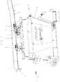
- Fig. 1 shows a part of an automatic agricultural plant FA, for example, for livestock, such as cattle, with a stationary installed schienenrange 1 from an upright arranged I-beam 2 (IPE profile), for example, also follows a curve 3 and leads to a slope 4.
- IPE profile I-beam 2
- a self-propelled robot R is suspended in the embodiment shown, two trolleys 8 and 9, which has at least one container 6 for food.
- the robot R can be used as feeding robot, litter robot or distribution robot.
- other equipment the robot R such as a battery assembly, a controller for an electric or hydraulic motor, sensors, a discharge device, or the like, as is usual for such robot R.
- a continuously or partially installed busbar for the electrical supply of the robot R.
- FIG Fig. 1 hangs the container 6 on a traverse 7, which in turn depends on the trolleys 8, 9 on the suspension rail track 1. It has only the trolley 9 a traction drive 10, although the other trolley 8 could have a traction drive.
- the traction drive 10 has a combination of a friction wheel drive F and a gear drive A, which will be explained in detail later.
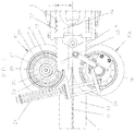
- a profile 5 is installed, with which the gear drive A can cooperate in a form-locking drive connection.
- the I-beam 2 has upper and lower transverse webs 12, 13 and a high web 11. Both trolleys 8, 9 additionally have rigidly mounted support rollers 14 which act on the opposite sides of the high web 11, and support rollers 15, which are free-running and run on the transverse web 13.
- the traction drive 10 of the trolley 9 has an electric or hydraulic drive motor 16, a braking device 17 and optionally a reduction gear 18 to drive a drive shaft X common to the friction wheel drive F and the gear drive A.
- a reduction gear 18 to drive a drive shaft X common to the friction wheel drive F and the gear drive A.
- separate drive shafts and separate drive motors could be provided.
- the reduction gear can be omitted.
- the friction-wheel drive F has a friction wheel 19 equipped with a rubber or elastomer support (eg neoprene) which can be pressed against one side of the high web 11 by a spring arrangement 21 in a spring-biased manner, and (in FIG Fig. 2 not visible) a freewheeling Friction wheel (19 'in Fig. 3 ), which is also under the spring preload against the opposite side of the high web 11 can be pressed.
- a rubber or elastomer support eg neoprene
- the gear drive A has on the common to the friction wheel 19 shaft X a drive gear 20 with engagement elements 25 such as involute tooth shape, which are intended for positive engagement in the engagement recesses 22 of the profile 5 and in Fig. 2 already engaged. Since the drive gear 20 and the friction wheel 19 have different effective diameters (the friction wheel 19 is larger than the drive gear 20) is in this phase of operation with positive transmission of a drive or braking torque, the friction wheel 19 lifted from the web 11 and only the drive gear 20 with the profile 5 in engagement.
- engagement elements 25 such as involute tooth shape
- Fig. 4 illustrates an operating phase in which the self-propelled robot R is driven in the system FA by means of the friction wheel drive F, whereas the gear drive A is still ineffective. Both friction wheels 19, 19 'are frictionally pressed against the high web 11 via the spring device 21.
- the robot R approaches the section 4 of the suspension rail track 1, for example, from the left.
- the profile 5, which may be designed in the manner of a toothed rack and screwed interchangeably with oblong holes 40 on the transverse web 13, consists for example of steel, which may be hardened at least in the region of the engagement recesses 22.
- an initial insertion bevel 23 may be provided.
- the drive gear 20 has two spaced apart wheel disks 27 which are rigidly connected with one another via the shaft X and in which the engagement elements 25 are fastened with their ends in the form of transverse pins.
- the contour of the engagement recesses 22 is approximately semicircular between convexly rounded teeth, while the outer periphery of the engagement elements 25 may be circular.
- the the engaging elements 25 forming pins are useful in pivot bearings 26 (not drawn in detail, eg plain bearings, ball bearings or needle roller bearings). mounted rotatably and interchangeably in the wheel discs 27 and expediently consist of steel, which may be hardened.
- the pins forming the engagement members 25 could be interchangeably anchored in the wheel discs 27 and carry rotatable sleeves (not shown).
- the drive gear 20 is formed in the manner of a gear with involute teeth, and the profile is designed in the manner of a rack.
- each engagement recess 22 is spaced from the web 11 by a distance Y which is tuned to the radius Y 'of the friction wheel 19 the friction wheel 19 is lifted automatically.
- the bias of the spring assembly 21 is used to press the engagement elements 25 in the engagement recesses 22.
- the contact forces of the friction wheel 19 and the drive gear 20 are appropriately in equilibrium.
- the switching between the two types of drive could, however, in other ways, for. B. control technology, be made.
- At least one engagement element 25 of the drive gear 20 is in engagement with an involute engagement recess 22 of the profile 5 in order to transmit the drive or braking torque of the traction drive 10 in a form-fitting manner. Thanks to the matched to the radius Y 'of the rotationally driven friction wheel 19 distance Y of the respective engagement recess 22 from the web 11, the rotationally driven friction wheel 19 is lifted from the high web 11 by the meshing drive gear eg (involute tooth shape) against the action of the spring means 21 and the engagement member 25 accordingly strongly pressed into the engagement recess 22. This engagement situation is also supported by the action of the support rollers 14 and the rollers 15.
- the beginning and end portions of the profile 5 may be designed such that it is ensured that the rotationally driven friction wheel 19 brings the first engagement element 25 securely into the first engagement recess 22 or the robot R is reliably moved out of the profile 5 by the rotationally driven friction wheel 19.
- the traction drive is designed so that the friction wheel drive F brings the gear drive A in function and the friction wheel drive F is only then released, or the rotationally driven friction wheel 19 is already brought back into operation before the gear drive is disabled.
- a blocking device 28 for example an adjustable Switzerlandschraubspindel
- a blocking device 28 which prevents at least skipping the drive wheel 20.
- the invention is not limited to the illustrated design features.
- the profile 5 could also be provided at other positions of the suspension rail track 1, as shown.
- the friction wheel drive F and the gear drive A could be designed and positioned differently.
Abstract
In einer landwirtschaftlichen Anlage (FA), insbesondere für Nutzvieh, mit einer ortsfest verbauten Hängeschienenstrecke (1) und wenigstens einem hängend an der Hängeschienenstrecke (1) selbstfahrenden, wenigstens einen Behälter (6) und wenigstens einen drehangetriebenen Fahrantrieb (19) aufweisenden Roboter (R), wobei zum Übertragen von Fahr- und Brems-Drehmomenten zwischen dem Roboter (R) und der Hängeschienenstrecke (1) eine mechanische Antriebsverbindung vorgesehen ist, ist in einem Abschnitt (4) der Hängeschienenstrecke (1) zwischen dem Roboter (R) und der Hängeschienenstrecke (1) eine formschlüssige Antriebsverbindung herstellbar.In an agricultural plant (FA), in particular for livestock, with a stationary installed hängeschienenstrecke (1) and at least one hanging on the Hängeschienenstrecke (1) self-propelled, at least one container (6) and at least one rotationally driven traction drive (19) having robots (R ), wherein for transmitting driving and braking torques between the robot (R) and the suspension rail track (1) is provided a mechanical drive connection is in a section (4) of the suspension rail track (1) between the robot (R) and the Hängeschienenstrecke (1) a positive drive connection produced.
Description
Die Erfindung betrifft eine landwirtschaftliche Anlage gemäß Oberbegriff des Anspruchs 1 sowie einen selbstfahrenden Roboter gemäß Oberbegriff des Anspruchs 14.The invention relates to an agricultural installation according to the preamble of
Obwohl es bei automatischen landwirtschaftlichen Anlagen eine Tendenz zu auf Räder fahrenden Robotern gibt, besteht dennoch Bedarf für hängende Roboter, wenn z.B. verschiedene Stellen der Anlage oder verschiedene Gebäude auf unterschiedlichen Höhen liegen, die von bodengestützten Robotern nicht zu überwinden sind. Eine Hängeschienenstrecke mit Steigungen oder Gefällen und ein hängender Roboter ist eine Lösung dieser Problematik.Although there is a tendency for wheeled robots in automatic agricultural equipment, there is still a need for hanging robots when e.g. Different locations of the plant or different buildings are at different heights, which are not to be overcome by ground-based robots. A hanging rail track with gradients or slopes and a hanging robot is a solution to this problem.
In solchen Anlagen landwirtschaftlicher Betriebe transportiert wenigstens ein an der Hängeschienenstrecke selbstfahrender Roboter als Fütterroboter beispielsweise Futter oder als Einstreuroboter Einstreumaterial, das an vorbestimmten Stellen vorbereitet und in den Behälter gefüllt wird, entweder zu Fütterstellen oder Einstreustellen oder zur Übergabe an einen Verteilroboter. Hängende Roboter können bis 3 t oder mehr wiegen (inklusive Ladung) und benötigen ein hohes Antriebsdrehmoment bzw. Bremsmoment, um Steigungen und Gefälle überwinden zu können bzw. an vorbestimmten Stellen anzuhalten, oder bei Gefällen abzubremsen.In such facilities of agricultural enterprises transported at least one on the Hängeschienenstrecke self-propelled robot feeding as feed or strewing as Einstreuroboter bedding material that is prepared at predetermined locations and filled in the container, either to feeding points or Einstrepositionen or for transfer to a distribution robot. Hanging robots can weigh up to 3 t or more (including cargo) and require a high drive torque or braking torque to overcome inclines and gradients or to stop at predetermined points, or to decelerate on gradients.
Beispiele solcher Anlagen bzw. Roboter sind enthalten in
Der Erfindung liegt die Aufgabe zugrunde, eine landwirtschaftliche Anlage der eingangs genannten Art sowie einen selbstfahrenden Roboter anzugeben, mit denen auch Betriebssituationen einwandfrei beherrschbar sind, in denen wegen äußerer Einflüsse kein ausreichender Reibschluss möglich ist, d. h., auch kritische oder sehr steile Abschnitte problemlos durchfahren werden oder der Roboter dort sicher angehalten bleibt.The invention has for its object to provide an agricultural system of the type mentioned above and a self-propelled robot, with which operating conditions are perfectly manageable, in which due to external influences sufficient frictional engagement is not possible, d. h., Even critical or very steep sections are passed through easily or the robot remains safely stopped there.
Die gestellte Aufgabe wird mit den Merkmalen des Anspruchs 1 und den Merkmalen des Anspruchs 14 gelöst.The stated object is achieved with the features of
Da in zumindest einem Abschnitt de Hängeschienenstrecke zwischen dem Roboter und der Hängeschienenstrecke eine formschlüssige Antriebsverbindung herstellbar ist, vermag der Roboter auch unter ungünstigen Außenbedingungen Steigungen und Gefälle oder grundsätzlich extreme Steigungen problemlos zu überwinden und jederzeit wie vorbestimmt sicher anzuhalten. Dies gilt beispielsweise auch beim Ein- oder Ausfahren in bzw. aus einem Stall, wo aufgrund der Temperaturunterschiede die Gefahr von Kondenswasser an der Hängeschienenstrecke besteht. Die formschlüssige Antriebsverbindung kann entweder nur in kritischen Abschnitten genutzt werden, oder entlang der gesamten Hängeschienenstrecke. Die formschlüssige Antriebsverbindung weil nicht reibungsabhängig, sondern funktioniert unter allen Betriebssituationen gleichartig gut.Since in at least one section de Hängeschienenstrecke between the robot and the Hängeschienenstrecke a positive drive connection can be produced, the robot is able to overcome slopes and gradients or basically extreme gradients easily under unfavorable outdoor conditions and stop at any time as predetermined safe. This also applies, for example, when entering or leaving a stable where, due to the temperature differences, there is a risk of condensation on the suspension rail track. The positive drive connection can be used either only in critical sections, or along the entire suspension rail track. The positive drive connection because not friction-dependent, but works equally well in all operating situations.
Der selbstfahrende Roboter weist in seinem wenigstens einen Fahrantrieb ein drehantreibbares Antriebsrad mit formschlüssigen Eingriffselementen auf, sodass er mit entsprechenden, an der Hängeschienenstrecke zumindest abschnittsweise vorgesehenen Eingriffsvertiefungen das Antriebs- oder Brems-Drehmoment zuverlässig formschlüssig zu übertragen vermag.The self-propelled robot has in its at least one traction drive a rotatably driven drive wheel with positive engagement elements, so that it is able to reliably reliably transmit the drive or braking torque positively with corresponding, at least partially provided on the suspension rail track engagement recesses.
In einer günstigen Ausführungsform der Fütteranlage ist in dem Abschnitt der Hängeschienenstrecke ein Profil mit Eingriffsvertiefungen verbaut, und weist der zumindest eine Fahrantrieb des Roboters in den Eingriffsvertiefungen zum formschlüssig drehmomentübertragenden Eingriff bringbare Eingriffselemente auf. Auf diese Weise ist eine weitestgehend reibungsunabhängige Übertragung des Antriebs- bzw. Brems-Drehmoments sichergestellt, d. h., der Roboter kann nach Art einer Zahnradbahn Gefälle und Steigungen überwinden und auch an jeder vorbestimmten Stelle sicher anhalten.In a favorable embodiment of the feeding system, a profile with engagement recesses is installed in the section of the suspension rail track, and the at least one travel drive of the robot has engageable engagement elements in the engagement recesses for the form-fitting torque-transmitting engagement. In this way, a largely friction-independent transmission of the drive or braking torque is ensured, d. h., The robot can overcome in the manner of a rack railway slope and slopes and also stop safely at any predetermined location.
In einer einfachen Ausführungsform ist das Profil an der Hängeschienenstrecke nach Art einer Zahnstange, vorzugsweise mit Gerad- oder Schrägverzahnung, ausgebildet, während die Eingriffselemente als Zähne eines Zahnrads oder Ritzels an diesen ausgebildet sind. Alternativ könnte das Profil als eine Art Rollengliederkette ausgebildet sein, deren Gelenke an der Hängeschienenstrecke festgelegt sind, und in die das Antriebsrad nach Art eines Kettenrads oder Ritzels eingreift. Als weitere Alternative könnte das Profil beispielsweise aus zwei beabstandeten Flacheisen mit dazwischen verankerten Querstiften oder Rollen für Zähne eines Antriebszahnrads (Kettenrad) ausgebildet sein, was die Anbringung an der Hängeschienenstrecke vereinfacht.In a simple embodiment, the profile on the suspension rail track in the manner of a rack, preferably with straight or helical teeth, formed while the engagement elements are formed as teeth of a gear or pinion on this. Alternatively, the profile could be formed as a kind of roller link chain, whose joints are fixed to the suspension rail track, and engages in the drive wheel in the manner of a sprocket or pinion. As a further alternative, the profile could for example be formed of two spaced flat iron with anchored thereon cross pins or rollers for teeth of a drive gear (sprocket), which simplifies the attachment to the suspension rail track.
Zweckmäßig sind die Eingriffsvertiefungen des Profils gerundet, vorzugsweise etwa halbkreisförmig, und sind die Eingriffselemente mit runder Kontur ausgebildet. Auf diese Weise wird großflächiger Eingriff mit niedriger spezifischer Belastung sichergestellt. Zweckmäßig sind jedoch die Eingriffsvertiefungen und die Eingriffselemente normale Zähne und Zahnvertiefungen z.B. mit Evolventenform, sodass zwischen dem Antriebszahnrad und den Eingriffsvertiefungen Abwälzbewegungen auftreten.Suitably, the engagement recesses of the profile are rounded, preferably approximately semicircular, and the engagement elements are formed with a round contour. In this way, large-scale engagement with low specific load is ensured. Conveniently, however, the engagement recesses and the engagement members are normal teeth and tooth recesses, e.g. with involute, so between the drive gear and the engaging recesses occur rolling movements.
Um demgegenüber den Verschleiß beim Eingriff zu minimieren, ist es zweckmäßig, wenn die Eingriffselemente am Zahnrad von quer- zum Profil orientierten Stiften gebildet sind, die entweder drehbar gelagert sind oder drehbare Hülsen tragen, sodass relative Abwälzbewegungen vermieden werden und mit Rollreibung gearbeitet wird.In contrast, to minimize the wear during engagement, it is useful if the engagement elements are formed on the gear of transversely to the profile oriented pins that are either rotatably mounted or carry rotatable sleeves, so that relative rolling movements are avoided and worked with rolling friction.
In einer einfachen Ausführungsform weist das Zahnrad zwei beabstandete, z.B. miteinander verbundene Radscheiben auf, in denen jeweils die Enden entweder der Hülsen tragenden Stifte austauschbar und festverankert oder der hülsenfreien Stifte austauschbar und drehbar gelagert sind. Die Austauschbarkeit der formschlüssig kooperierenden Komponenten ist wichtig, da der Formschluss zwangsweise verschleißbehaftet ist.In a simple embodiment, the gear has two spaced, for example, interconnected wheel discs, in each of which the ends of either the sleeve-bearing pins interchangeable and firmly anchored or the sleeve-free pins are interchangeable and rotatably mounted. The interchangeability of the form-fitting cooperating components is important because the form-fitting is forcibly subject to wear.
Ebenfalls zum Minimieren des Verschleißes ist es zweckmäßig, dass zumindest die Eingriffsvertiefungen und/oder die Eingriffselemente aus gehärtetem Stahl bestehen.Also, to minimize wear, it is desirable that at least the engagement recesses and / or the engagement elements be made of hardened steel.
Zweckmäßig ist der das Profil aufweisende Abschnitt der Hängeschienenstrecke ein Abschnitt mit einem Gefälle oder einer Steigung oder gegebenenfalls einer engen Kurve, weil in diesen Abschnitten der Hängeschienenstrecke die größte Gefahr eines zu schwachen Reibschlusses auftreten kann.Suitably, the profile having portion of the suspension rail track is a section with a slope or a slope or possibly a tight curve, because in these sections of the suspension rail track the greatest risk of too weak frictional engagement can occur.
Das Profil kann an der Hängeschienenstrecke entweder austauschbar verbaut sein, oder alternativ sogar direkt eingeformt werden.The profile can either be installed interchangeably on the suspended rail track, or alternatively even molded directly.
Da eine durchgehende Ausstattung der Hängeschienenstrecke mit dem Profil baulich aufwändig und teuer ist, werden nur kritische Abschnitte mit dem Profil ausgestattet, und weist der Fahrantrieb des Roboters eine Kombination aus einem Reibrad-Antrieb und einem formschlüssigen Antrieb, z. B. Zahnrad-Antrieb, auf, wobei, vorzugsweise, zwischen beiden Antriebsarten umgestellt werden kann. Dies bedeutet, dass der Roboter in problemlosen Abschnitten der Hängeschienenstrecke mittels des Reibrad-Antriebs angetrieben und abgebremst wird, und nur in kritischen Abschnitten über den Formschluss angetrieben und abgebremst wird. Die Kombination der beiden Antriebsarten ist ein wesentlicher Aspekt der Erfindung.Since a continuous equipment of Hängeschienenstrecke with the profile is structurally complex and expensive, only critical sections are equipped with the profile, and the drive of the robot has a combination of a friction wheel drive and a positive drive, for. B. gear drive on, wherein, preferably, can be switched between two types of drive. This means that the robot is driven and braked in trouble-free sections of the suspension rail track by means of the friction wheel drive, and is driven and braked only in critical sections via the positive locking. The combination of the two drive types is an essential aspect of the invention.
Bei einer zweckmäßigen Ausführungsform ist der Wirkdurchmesser des Zahnrad-Antriebs bzw. des Zahnrads kleiner als der Wirkdurchmesser des Reibrad-Antriebs. Dies bietet den Vorteil, in unkritischen Abschnitten der Hängeschienenstrecke mit gleicher Antriebsdrehzahl relativ schnell fahren zu können, hingegen in kritischen Abschnitten ein größeres Antriebs- oder Bremsmoment erzeugen zu können. Dies soll nicht ausschließen, die Wirkdurchmesser der beiden Antriebe gleich zu wählen, und den Fahrantrieb nicht umzustellen.In an advantageous embodiment, the effective diameter of the gear drive or the gear is smaller than the effective diameter of the friction wheel drive. This offers the advantage of being able to drive relatively quickly in uncritical sections of the suspension track with the same drive speed, whereas in critical sections a larger drive or braking torque can be generated. This should not exclude the same, to choose the effective diameter of the two drives, and not to change the travel drive.
In einer zweckmäßigen Ausführungsform ist die Hängeschienenstrecke ein stehend verbauter-I-Träger (IPE-Profil), wobei dann der Reibrad-Antrieb am Hochsteg und der Zahnrad-Antrieb im Bereich eines Querstegs des I-Trägers angreifen kann.In an expedient embodiment, the suspension rail track is a standing I-beam (IPE profile), in which case the friction wheel drive on the high web and the gear drive can engage in the region of a transverse web of the I beam.
In einer zweckmäßigen Ausführungsformen teilen sich der Reibrad-Antrieb und der Zahnrad-Antrieb eine gemeinsame Antriebswelle, die mit einem elektrischen oder hydraulischen Antriebsmotor und einer Bremsvorrichtung gekuppelt ist, gegebenenfalls über ein Reduktionsgetriebe. Dies bedeutet eine bauliche Vereinfachung und ist platzsparend. Alternativ können für den Reibrad-Antrieb und den Zahnrad-Antrieb getrennte Antriebswellen vorgesehen sein Auch falls mehrere Reibräder und/oder Zahnräder angetrieben sind.In an expedient embodiment, the friction wheel drive and the gear drive share a common drive shaft, which is coupled to an electric or hydraulic drive motor and a brake device, optionally via a reduction gear. This means a structural simplification and saves space. Alternatively you can be provided for the friction wheel drive and the gear drive separate drive shafts Even if multiple friction wheels and / or gears are driven.
In einer zweckmäßigen Ausführungsform weist der Reibrad-Antrieb wenigstens ein angetriebenes Reibrad und ein freilaufendes Reibrad auf, die wahlweise mit Federvorspannung an gegenüberliegende Seiten des Hochstegs anpressbar sind, wobei, vorzugsweise, das angetriebene Reibrad bei Eingriff der Eingriffselemente in den Eingriffsvertiefungen vom Hochsteg abhebbar ist, speziell bei unterschiedlichen Wirkdurchmessern. Die Anpresskräfte für das Reibrad und das Antriebszahnrad können im Gleichgewicht sein. Außerdem kann eine das Überspringen des Antriebszahnrads verhindernde Blockiervorrichtung im Federantrieb zweckmäßig sein.In an expedient embodiment, the friction wheel drive has at least one driven friction wheel and a free-running friction wheel which can be pressed with spring preload on opposite sides of the high web, wherein, preferably, the driven friction wheel can be lifted from the high web when the engagement elements engage in the engagement recesses, especially with different effective diameters. The contact forces for the friction wheel and the drive gear can be in equilibrium. In addition, a skip preventing the drive gear blocking device may be useful in the spring drive.
Bei getrennten Wellen des Reibrad-Antriebs und des Zahnrad-Antriebs und gegebenenfalls getrennten Antriebsmotoren kann bei unterschiedlichen Wirkdurchmessern steuerungsseitig zwischen den Antriebsarten umgestellt werden. Baulich und steuerungstechnisch einfach sind jedoch das Profil das angetriebene Reibrad und das Zahnrad so aufeinander abgestimmt angeordnet, dass jede Eingriffsvertiefung mit ihrem Grund vom Hochsteg des I-Trägers einen Abstand hat, der sicherstellt, dass sobald die Eingriffselemente in die Eingriffsvertiefungen eingreifen, das angetriebene Reibrad automatisch vom Hochsteg abgedrückt und somit vorübergehend funktionslos wird, obwohl es weiterhin angetrieben wird.With separate shafts of the friction wheel drive and the gear drive and optionally separate drive motors can be switched at different effective diameters control side between the types of drive. Structurally and control technology simple, however, the profile of the driven friction wheel and the gear are arranged coordinated so that each engagement recess with its base from the web of the I-beam has a distance, which ensures that as soon as the engagement elements engage in the engagement recesses, the driven friction wheel automatically pushed off the high bridge and thus temporarily becomes inoperative, although it is still driven.
In einer zweckmäßigen Ausführungsform ist das Profil entweder ein starres Profil oder eine Gliederkette, wie eine Rollengliederkette, und auf oder unter einem Quersteg des I-Profils verschraubt, vorzugsweise derart, dass sein Abstand vom Hochsteg nach Bedarf einstellbar ist.In an expedient embodiment, the profile is either a rigid profile or a link chain, such as a roller link chain, and bolted to or under a transverse web of the I-profile, preferably such that its distance from the web is adjustable as needed.
Wie erwähnt, können der Reibrad-Antrieb und der Zahnrad-Antrieb des Roboters Räder auf separaten Wellen aufweisen, und, vorzugsweise, mit getrennten Antriebsmotoren und Bremsvorrichtungen gekoppelt sein.As mentioned, the wheel friction drive and the gear drive of the robot may have wheels on separate shafts and, preferably, be coupled to separate drive motors and braking devices.
Um den ordnungsgemäßen Eingriff zwischen den Eingriffselementen und den Eingriffsvertiefungen in dem Abschnitt der Hängeschienenstrecke sicherzustellen, und auch den Reibrad-Antrieb nur zur Übertragung des Antriebs- oder Brems-Drehmoments einzusetzen und von Führungsaufgaben des Roboters freizustellen, ist es zweckmäßig, wenn der jeweilige Fahrantrieb des Roboters zusätzlich mit starr verbauten, freilaufenden Stützrollen z.B. an beiden Seiten des Hochstegs und mit Laufrollen z.B. auf dem Quersteg abgestützt ist.In order to ensure the proper engagement between the engagement elements and the engagement recesses in the section of Hängeschienenstrecke, and also use the friction wheel drive only to transmit the drive or braking torque and exempt from leadership tasks of the robot, it is useful if the respective drive of the Robot is additionally supported with rigidly mounted, free-running support rollers, for example, on both sides of the high bridge and with rollers, for example on the cross bar.
Um einen stabilen Lauf des Roboters sicherzustellen, ist es zweckmäßig, wenn der Roboter mit zwei beabstandeten Laufkatzen oder Laufwagen an der Hängeschienenstrecke fährt, wobei, vorzugsweise, nur eine Laufkatze den wenigstens einen Fahrantrieb aufweisen kann.In order to ensure a stable running of the robot, it is expedient if the robot moves with two spaced trolleys or carriages on the suspension rail track, wherein, preferably, only one trolley can have the at least one traction drive.
Gemäß eines wichtigen Aspekts des selbstfahrenden Roboters weist dessen Fahrantrieb eine Kombination eines Reibrad-Antriebs und eines formschlüssigen Zahnrad-Antriebs auf, wobei diese Kombination zwischen den beiden Antriebsarten umstellbar sein kann.According to an important aspect of the self-propelled robot, its traction drive has a combination of a friction wheel drive and a positive gear drive, wherein this combination between the two types of drive can be switched.
An dem selbstfahrenden Roboter kann der Fahrantrieb für den Reibrad-Antrieb wenigstens ein drehantreibbares Reibrad und für den formschlüssigen Zahnrad-Antrieb wenigstens ein drehbares Antriebselement mit den Eingriffselementen umfassen, vorzugsweise jeweils auf einer gemeinsamen Antriebswelle. Die Umstellung zwischen den beiden Antriebsarten kann wahlweise oder automatisch erfolgen.On the self-propelled robot, the travel drive for the friction wheel drive may comprise at least one friction-driven friction wheel and, for the positive-toothed gear drive, at least one rotatable drive element with the engagement elements, preferably each on a common drive shaft. The changeover between the two types of drive can be either optional or automatic.
Anhand der Zeichnungen werden Ausführungsformen des Erfindungsgegenstandes erläutert. Es zeigen:
- Fig. 1
- eine perspektivische Seitenansicht eines Abschnitts einer Hängeschienenstrecke einer landwirtschaftlichen Anlage mit einem selbstfahrenden Roboter,
- Fig. 2
- einen vergrößerten Ausschnitt aus
Fig. 1 , - Fig. 3
- eine Ansicht in Längsrichtung der Hängeschienenstrecke mit einem Fahrantrieb des Roboters,
- Fig. 4
- eine Seitenansicht einer Betriebsphase des Roboters bei Nutzen eines Reibrad-Antriebs, und
- Fig. 5
- eine Seitenansicht einer Betriebsphase des Roboters bei Nutzen einer formschlüssigen Antriebsverbindung zwischen dem Fahrantrieb und der Hängeschienenstrecke.
- Fig. 1
- 3 a perspective side view of a section of a suspension track of an agricultural installation with a self-propelled robot,
- Fig. 2
- an enlarged section
Fig. 1 . - Fig. 3
- a view in the longitudinal direction of the suspension rail track with a drive of the robot,
- Fig. 4
- a side view of an operating phase of the robot using a friction wheel drive, and
- Fig. 5
- a side view of an operating phase of the robot using a positive drive connection between the drive and the suspension rail track.
In der gezeigten Ausführungsform in
In der vergrößerten Darstellung in
Der Fahrantrieb 10 der Laufkatze 9 weist einen elektrischen oder hydraulischen Antriebsmotor 16, eine Bremsvorrichtung 17 und gegebenenfalls ein Reduktionsgetriebe 18 auf, um eine dem Reibrad-Antrieb F und dem Zahnrad-Antrieb A gemeinsame Antriebswelle X anzutreiben. Alternativ könnten getrennte Antriebswellen und getrennte Antriebsmotoren vorgesehen sein. Mit einem langsam laufenden Gleichstrommotor kann das Reduktionsgetriebe entfallen.The traction drive 10 of the
Das an der Unterseite des Querstegs 13 vorzugsweise austauschbar befestigte Profil 5 ist hier ein starres Profil 24 beispielsweise aus Stahl, das z.B. gegenüber dem Quersteg 13 zu einer Seite vorspringt und mit regelmäßig verteilten, hier seitlich offenen Eingriffsvertiefungen 22 mit dazwischenliegenden, Evolventen-Zähnen, ausgebildet ist. Der Reibrad-Antrieb F weist in der gezeigten Ausführungsform ein mit einer Gummi- oder Elastomerauflage (z.B. Neopren) ausgestattetes Reibrad 19 auf, das an eine Seite des Hochstegs 11 über eine Federanordnung 21 federvorgespannt anpressbar ist, und (in
Der Zahnrad-Antrieb A weist auf der mit dem Reibrad 19 gemeinsamen Welle X ein Antriebszahnrad 20 mit Eingriffselementen 25 z.B. Evolventen-Zahnform auf, die zum formschlüssigen Eingriff in die Eingriffsvertiefungen 22 des Profils 5 bestimmt sind und in
In der Ansicht des Fahrantriebs 10 und des I-Profils 2 in dessen Längsrichtung in
In der gezeigten Ausführungsform weist das Antriebszahnrad 20 zwei beabstandete und miteinander über die Welle X starr verbundene Radscheiben 27 auf, in welchen die Eingriffselemente 25 in Form von Querstiften mit ihren Enden befestigt sind. Die Kontur der Eingriffsvertiefungen 22 ist annähernd halbkreisförmig zwischen konvex gerundeten Zähnen, während der Außenumfang der Eingriffselemente 25 kreisrund sein kann. Die die Eingriffselemente 25 bildenden Stifte sind zweckmäßig in Drehlagern 26 (nicht im Detail gezeichnet, z.B. Gleitlager, Kugellager oder Nadellager). in den Radscheiben 27 drehbar und austauschbar gelagert und bestehen zweckmäßig aus Stahl, der gehärtet sein kann. Alternativ könnten die die Eingriffselemente 25 bildenden Stifte in den Radscheiben 27 austauschbar verankert sein und drehbare Hülsen (nicht gezeigt) tragen.In the embodiment shown, the
Alternativ (wie in
Um sicherzustellen, dass dann bei Nutzen des Zahnrad-Antriebs A (siehe
In der Betriebsphase in
In anderen Worten ist der Fahrantrieb so konzipiert, dass der Reibrad-Antrieb F den Zahnrad-Antrieb A in Funktion bringt und der Reibrad-Antrieb F erst dann freigeschaltet wird, bzw. das drehangetriebene Reibrad 19 schon wieder in Funktion gebracht wird, bevor der Zahnrad-Antrieb außer Funktion genommen wird.In other words, the traction drive is designed so that the friction wheel drive F brings the gear drive A in function and the friction wheel drive F is only then released, or the rotationally driven
In den
Die Erfindung ist nicht auf die dargestellten konstruktiven Merkmale beschränkt. Das Profil 5 könnte auch an anderen Positionen der Hängeschienenstrecke 1 vorgesehen sein, als gezeigt Auch der Reibrad-Antrieb F und der Zahnrad-Antrieb A könnten anders gestaltet und positioniert sein.The invention is not limited to the illustrated design features. The
Claims (15)
Applications Claiming Priority (1)
| Application Number | Priority Date | Filing Date | Title |
|---|---|---|---|
| DE202017106626.6U DE202017106626U1 (en) | 2017-11-02 | 2017-11-02 | Agricultural plant and self-propelled robot |
Publications (2)
| Publication Number | Publication Date |
|---|---|
| EP3479688A1 true EP3479688A1 (en) | 2019-05-08 |
| EP3479688B1 EP3479688B1 (en) | 2021-02-24 |
Family
ID=65441820
Family Applications (1)
| Application Number | Title | Priority Date | Filing Date |
|---|---|---|---|
| EP18188714.2A Active EP3479688B1 (en) | 2017-11-02 | 2018-08-13 | Agricultural plant and self-propelled robot |
Country Status (2)
| Country | Link |
|---|---|
| EP (1) | EP3479688B1 (en) |
| DE (1) | DE202017106626U1 (en) |
Cited By (1)
| Publication number | Priority date | Publication date | Assignee | Title |
|---|---|---|---|---|
| CN113829324A (en) * | 2021-09-27 | 2021-12-24 | 诠航科技有限公司 | Driving wheel set of hanger rail type inspection robot and hanger rail type inspection robot |
Families Citing this family (2)
| Publication number | Priority date | Publication date | Assignee | Title |
|---|---|---|---|---|
| CN113815655A (en) * | 2021-01-08 | 2021-12-21 | 京东科技信息技术有限公司 | Rail-mounted driving device and driving system, rail-mounted robot and robot system |
| CN114906175A (en) * | 2021-02-08 | 2022-08-16 | 京东科技信息技术有限公司 | Running gear and hang rail robot |
Citations (7)
| Publication number | Priority date | Publication date | Assignee | Title |
|---|---|---|---|---|
| US2685863A (en) * | 1950-07-29 | 1954-08-10 | Pacific Dairy Machinery Co | Self-dumping monorail live stock feed dispenser |
| DE2344596A1 (en) * | 1973-08-29 | 1975-03-06 | Helmut Hofmann | Automatic travelling fodder dispenser - has fodder dispenser driven by rubber wheels engaging steel track |
| US4223638A (en) | 1979-01-24 | 1980-09-23 | Sappington Marr D | Apparatus for feeding poultry |
| US4672917A (en) | 1985-02-26 | 1987-06-16 | Fox Harvey Z | Feeder |
| US4981107A (en) | 1989-03-31 | 1991-01-01 | Micro-Contact Inc. | Computerized automatic cattle-feeder system |
| US5069165A (en) | 1990-10-12 | 1991-12-03 | Victor Rousseau | Livestock feeder system |
| EP2263452A1 (en) * | 2009-06-16 | 2010-12-22 | TECNIPLAST S.p.A. | Automated system for controlled distribution of substances to animal containment devices in an animal housing facility |
-
2017
- 2017-11-02 DE DE202017106626.6U patent/DE202017106626U1/en active Active
-
2018
- 2018-08-13 EP EP18188714.2A patent/EP3479688B1/en active Active
Patent Citations (7)
| Publication number | Priority date | Publication date | Assignee | Title |
|---|---|---|---|---|
| US2685863A (en) * | 1950-07-29 | 1954-08-10 | Pacific Dairy Machinery Co | Self-dumping monorail live stock feed dispenser |
| DE2344596A1 (en) * | 1973-08-29 | 1975-03-06 | Helmut Hofmann | Automatic travelling fodder dispenser - has fodder dispenser driven by rubber wheels engaging steel track |
| US4223638A (en) | 1979-01-24 | 1980-09-23 | Sappington Marr D | Apparatus for feeding poultry |
| US4672917A (en) | 1985-02-26 | 1987-06-16 | Fox Harvey Z | Feeder |
| US4981107A (en) | 1989-03-31 | 1991-01-01 | Micro-Contact Inc. | Computerized automatic cattle-feeder system |
| US5069165A (en) | 1990-10-12 | 1991-12-03 | Victor Rousseau | Livestock feeder system |
| EP2263452A1 (en) * | 2009-06-16 | 2010-12-22 | TECNIPLAST S.p.A. | Automated system for controlled distribution of substances to animal containment devices in an animal housing facility |
Cited By (1)
| Publication number | Priority date | Publication date | Assignee | Title |
|---|---|---|---|---|
| CN113829324A (en) * | 2021-09-27 | 2021-12-24 | 诠航科技有限公司 | Driving wheel set of hanger rail type inspection robot and hanger rail type inspection robot |
Also Published As
| Publication number | Publication date |
|---|---|
| DE202017106626U1 (en) | 2019-02-06 |
| EP3479688B1 (en) | 2021-02-24 |
Similar Documents
| Publication | Publication Date | Title |
|---|---|---|
| DE2409958C3 (en) | Sponsor | |
| EP3479688B1 (en) | Agricultural plant and self-propelled robot | |
| DE19758346A1 (en) | Management system | |
| DE3128824C2 (en) | Electric monorail | |
| DE3546923C2 (en) | Overhead transporter system for factory | |
| DE3715904C1 (en) | Self-propelled trolley for driving along a covered rope | |
| EP1375390B1 (en) | Device for transporting articles | |
| EP3033284A1 (en) | Conveying device having a large-area conveying member | |
| EP1412265B1 (en) | Accumulation-capable curved element for a transfer system | |
| WO2002004273A1 (en) | Transport system | |
| DE3338425C2 (en) | ||
| DE3713431C2 (en) | ||
| WO2018078105A1 (en) | Accumulating conveyor | |
| WO1996041739A1 (en) | Electric trolley conveyor for transporting widely varying loads over various planes | |
| DE4128890C2 (en) | Plant for treating products | |
| DE19516775A1 (en) | Platform for transporter of collector | |
| DE3517291C2 (en) | ||
| DE1927537B2 (en) | Belt sintering machine | |
| EP2390205B1 (en) | Modular conveyor | |
| DE202004001810U1 (en) | Assembly trolley for accumulating roller conveyor has adjustable pressure of carrier on conveyor | |
| EP1356727B1 (en) | Device for walking and training animals along a defined track | |
| WO2010100532A1 (en) | Cable railway bogie having pulling cables, cable car, and cable railway system | |
| DE1295584C2 (en) | Drive for a monorail | |
| DE4042742B4 (en) | Conveying apparatus for contacting bodies - comprises drive device including drive roller movable into contact with side of body | |
| DE3434195C1 (en) | Apparatus for fitting an elongate element, in particular a pipe |
Legal Events
| Date | Code | Title | Description |
|---|---|---|---|
| PUAI | Public reference made under article 153(3) epc to a published international application that has entered the european phase |
Free format text: ORIGINAL CODE: 0009012 |
|
| STAA | Information on the status of an ep patent application or granted ep patent |
Free format text: STATUS: THE APPLICATION HAS BEEN PUBLISHED |
|
| AK | Designated contracting states |
Kind code of ref document: A1 Designated state(s): AL AT BE BG CH CY CZ DE DK EE ES FI FR GB GR HR HU IE IS IT LI LT LU LV MC MK MT NL NO PL PT RO RS SE SI SK SM TR |
|
| AX | Request for extension of the european patent |
Extension state: BA ME |
|
| STAA | Information on the status of an ep patent application or granted ep patent |
Free format text: STATUS: REQUEST FOR EXAMINATION WAS MADE |
|
| 17P | Request for examination filed |
Effective date: 20191028 |
|
| RBV | Designated contracting states (corrected) |
Designated state(s): AL AT BE BG CH CY CZ DE DK EE ES FI FR GB GR HR HU IE IS IT LI LT LU LV MC MK MT NL NO PL PT RO RS SE SI SK SM TR |
|
| STAA | Information on the status of an ep patent application or granted ep patent |
Free format text: STATUS: EXAMINATION IS IN PROGRESS |
|
| 17Q | First examination report despatched |
Effective date: 20200219 |
|
| GRAP | Despatch of communication of intention to grant a patent |
Free format text: ORIGINAL CODE: EPIDOSNIGR1 |
|
| STAA | Information on the status of an ep patent application or granted ep patent |
Free format text: STATUS: GRANT OF PATENT IS INTENDED |
|
| INTG | Intention to grant announced |
Effective date: 20200922 |
|
| GRAS | Grant fee paid |
Free format text: ORIGINAL CODE: EPIDOSNIGR3 |
|
| GRAA | (expected) grant |
Free format text: ORIGINAL CODE: 0009210 |
|
| STAA | Information on the status of an ep patent application or granted ep patent |
Free format text: STATUS: THE PATENT HAS BEEN GRANTED |
|
| AK | Designated contracting states |
Kind code of ref document: B1 Designated state(s): AL AT BE BG CH CY CZ DE DK EE ES FI FR GB GR HR HU IE IS IT LI LT LU LV MC MK MT NL NO PL PT RO RS SE SI SK SM TR |
|
| REG | Reference to a national code |
Ref country code: CH Ref legal event code: EP |
|
| REG | Reference to a national code |
Ref country code: AT Ref legal event code: REF Ref document number: 1363321 Country of ref document: AT Kind code of ref document: T Effective date: 20210315 |
|
| REG | Reference to a national code |
Ref country code: IE Ref legal event code: FG4D Free format text: LANGUAGE OF EP DOCUMENT: GERMAN |
|
| REG | Reference to a national code |
Ref country code: DE Ref legal event code: R096 Ref document number: 502018003979 Country of ref document: DE |
|
| REG | Reference to a national code |
Ref country code: NL Ref legal event code: FP |
|
| REG | Reference to a national code |
Ref country code: LT Ref legal event code: MG9D |
|
| PG25 | Lapsed in a contracting state [announced via postgrant information from national office to epo] |
Ref country code: LT Free format text: LAPSE BECAUSE OF FAILURE TO SUBMIT A TRANSLATION OF THE DESCRIPTION OR TO PAY THE FEE WITHIN THE PRESCRIBED TIME-LIMIT Effective date: 20210224 Ref country code: NO Free format text: LAPSE BECAUSE OF FAILURE TO SUBMIT A TRANSLATION OF THE DESCRIPTION OR TO PAY THE FEE WITHIN THE PRESCRIBED TIME-LIMIT Effective date: 20210524 Ref country code: PT Free format text: LAPSE BECAUSE OF FAILURE TO SUBMIT A TRANSLATION OF THE DESCRIPTION OR TO PAY THE FEE WITHIN THE PRESCRIBED TIME-LIMIT Effective date: 20210624 Ref country code: BG Free format text: LAPSE BECAUSE OF FAILURE TO SUBMIT A TRANSLATION OF THE DESCRIPTION OR TO PAY THE FEE WITHIN THE PRESCRIBED TIME-LIMIT Effective date: 20210524 Ref country code: GR Free format text: LAPSE BECAUSE OF FAILURE TO SUBMIT A TRANSLATION OF THE DESCRIPTION OR TO PAY THE FEE WITHIN THE PRESCRIBED TIME-LIMIT Effective date: 20210525 Ref country code: FI Free format text: LAPSE BECAUSE OF FAILURE TO SUBMIT A TRANSLATION OF THE DESCRIPTION OR TO PAY THE FEE WITHIN THE PRESCRIBED TIME-LIMIT Effective date: 20210224 Ref country code: HR Free format text: LAPSE BECAUSE OF FAILURE TO SUBMIT A TRANSLATION OF THE DESCRIPTION OR TO PAY THE FEE WITHIN THE PRESCRIBED TIME-LIMIT Effective date: 20210224 |
|
| PG25 | Lapsed in a contracting state [announced via postgrant information from national office to epo] |
Ref country code: SE Free format text: LAPSE BECAUSE OF FAILURE TO SUBMIT A TRANSLATION OF THE DESCRIPTION OR TO PAY THE FEE WITHIN THE PRESCRIBED TIME-LIMIT Effective date: 20210224 Ref country code: RS Free format text: LAPSE BECAUSE OF FAILURE TO SUBMIT A TRANSLATION OF THE DESCRIPTION OR TO PAY THE FEE WITHIN THE PRESCRIBED TIME-LIMIT Effective date: 20210224 Ref country code: PL Free format text: LAPSE BECAUSE OF FAILURE TO SUBMIT A TRANSLATION OF THE DESCRIPTION OR TO PAY THE FEE WITHIN THE PRESCRIBED TIME-LIMIT Effective date: 20210224 Ref country code: LV Free format text: LAPSE BECAUSE OF FAILURE TO SUBMIT A TRANSLATION OF THE DESCRIPTION OR TO PAY THE FEE WITHIN THE PRESCRIBED TIME-LIMIT Effective date: 20210224 |
|
| PG25 | Lapsed in a contracting state [announced via postgrant information from national office to epo] |
Ref country code: IS Free format text: LAPSE BECAUSE OF FAILURE TO SUBMIT A TRANSLATION OF THE DESCRIPTION OR TO PAY THE FEE WITHIN THE PRESCRIBED TIME-LIMIT Effective date: 20210624 |
|
| PG25 | Lapsed in a contracting state [announced via postgrant information from national office to epo] |
Ref country code: EE Free format text: LAPSE BECAUSE OF FAILURE TO SUBMIT A TRANSLATION OF THE DESCRIPTION OR TO PAY THE FEE WITHIN THE PRESCRIBED TIME-LIMIT Effective date: 20210224 Ref country code: CZ Free format text: LAPSE BECAUSE OF FAILURE TO SUBMIT A TRANSLATION OF THE DESCRIPTION OR TO PAY THE FEE WITHIN THE PRESCRIBED TIME-LIMIT Effective date: 20210224 Ref country code: SM Free format text: LAPSE BECAUSE OF FAILURE TO SUBMIT A TRANSLATION OF THE DESCRIPTION OR TO PAY THE FEE WITHIN THE PRESCRIBED TIME-LIMIT Effective date: 20210224 |
|
| REG | Reference to a national code |
Ref country code: DE Ref legal event code: R097 Ref document number: 502018003979 Country of ref document: DE |
|
| PG25 | Lapsed in a contracting state [announced via postgrant information from national office to epo] |
Ref country code: DK Free format text: LAPSE BECAUSE OF FAILURE TO SUBMIT A TRANSLATION OF THE DESCRIPTION OR TO PAY THE FEE WITHIN THE PRESCRIBED TIME-LIMIT Effective date: 20210224 Ref country code: RO Free format text: LAPSE BECAUSE OF FAILURE TO SUBMIT A TRANSLATION OF THE DESCRIPTION OR TO PAY THE FEE WITHIN THE PRESCRIBED TIME-LIMIT Effective date: 20210224 Ref country code: SK Free format text: LAPSE BECAUSE OF FAILURE TO SUBMIT A TRANSLATION OF THE DESCRIPTION OR TO PAY THE FEE WITHIN THE PRESCRIBED TIME-LIMIT Effective date: 20210224 |
|
| PLBE | No opposition filed within time limit |
Free format text: ORIGINAL CODE: 0009261 |
|
| STAA | Information on the status of an ep patent application or granted ep patent |
Free format text: STATUS: NO OPPOSITION FILED WITHIN TIME LIMIT |
|
| PG25 | Lapsed in a contracting state [announced via postgrant information from national office to epo] |
Ref country code: ES Free format text: LAPSE BECAUSE OF FAILURE TO SUBMIT A TRANSLATION OF THE DESCRIPTION OR TO PAY THE FEE WITHIN THE PRESCRIBED TIME-LIMIT Effective date: 20210224 Ref country code: AL Free format text: LAPSE BECAUSE OF FAILURE TO SUBMIT A TRANSLATION OF THE DESCRIPTION OR TO PAY THE FEE WITHIN THE PRESCRIBED TIME-LIMIT Effective date: 20210224 |
|
| 26N | No opposition filed |
Effective date: 20211125 |
|
| PG25 | Lapsed in a contracting state [announced via postgrant information from national office to epo] |
Ref country code: SI Free format text: LAPSE BECAUSE OF FAILURE TO SUBMIT A TRANSLATION OF THE DESCRIPTION OR TO PAY THE FEE WITHIN THE PRESCRIBED TIME-LIMIT Effective date: 20210224 |
|
| REG | Reference to a national code |
Ref country code: CH Ref legal event code: PL |
|
| PG25 | Lapsed in a contracting state [announced via postgrant information from national office to epo] |
Ref country code: MC Free format text: LAPSE BECAUSE OF FAILURE TO SUBMIT A TRANSLATION OF THE DESCRIPTION OR TO PAY THE FEE WITHIN THE PRESCRIBED TIME-LIMIT Effective date: 20210224 |
|
| REG | Reference to a national code |
Ref country code: BE Ref legal event code: MM Effective date: 20210831 |
|
| PG25 | Lapsed in a contracting state [announced via postgrant information from national office to epo] |
Ref country code: LI Free format text: LAPSE BECAUSE OF NON-PAYMENT OF DUE FEES Effective date: 20210831 Ref country code: IT Free format text: LAPSE BECAUSE OF FAILURE TO SUBMIT A TRANSLATION OF THE DESCRIPTION OR TO PAY THE FEE WITHIN THE PRESCRIBED TIME-LIMIT Effective date: 20210224 Ref country code: CH Free format text: LAPSE BECAUSE OF NON-PAYMENT OF DUE FEES Effective date: 20210831 |
|
| PG25 | Lapsed in a contracting state [announced via postgrant information from national office to epo] |
Ref country code: IS Free format text: LAPSE BECAUSE OF FAILURE TO SUBMIT A TRANSLATION OF THE DESCRIPTION OR TO PAY THE FEE WITHIN THE PRESCRIBED TIME-LIMIT Effective date: 20210624 Ref country code: LU Free format text: LAPSE BECAUSE OF NON-PAYMENT OF DUE FEES Effective date: 20210813 |
|
| PG25 | Lapsed in a contracting state [announced via postgrant information from national office to epo] |
Ref country code: IE Free format text: LAPSE BECAUSE OF NON-PAYMENT OF DUE FEES Effective date: 20210813 Ref country code: BE Free format text: LAPSE BECAUSE OF NON-PAYMENT OF DUE FEES Effective date: 20210831 |
|
| PGFP | Annual fee paid to national office [announced via postgrant information from national office to epo] |
Ref country code: NL Payment date: 20221028 Year of fee payment: 5 Ref country code: FR Payment date: 20221027 Year of fee payment: 5 |
|
| GBPC | Gb: european patent ceased through non-payment of renewal fee |
Effective date: 20220813 |
|
| P01 | Opt-out of the competence of the unified patent court (upc) registered |
Effective date: 20230524 |
|
| PG25 | Lapsed in a contracting state [announced via postgrant information from national office to epo] |
Ref country code: CY Free format text: LAPSE BECAUSE OF FAILURE TO SUBMIT A TRANSLATION OF THE DESCRIPTION OR TO PAY THE FEE WITHIN THE PRESCRIBED TIME-LIMIT Effective date: 20210224 |
|
| PG25 | Lapsed in a contracting state [announced via postgrant information from national office to epo] |
Ref country code: HU Free format text: LAPSE BECAUSE OF FAILURE TO SUBMIT A TRANSLATION OF THE DESCRIPTION OR TO PAY THE FEE WITHIN THE PRESCRIBED TIME-LIMIT; INVALID AB INITIO Effective date: 20180813 |
|
| PG25 | Lapsed in a contracting state [announced via postgrant information from national office to epo] |
Ref country code: GB Free format text: LAPSE BECAUSE OF NON-PAYMENT OF DUE FEES Effective date: 20220813 |
|
| PGFP | Annual fee paid to national office [announced via postgrant information from national office to epo] |
Ref country code: AT Payment date: 20230824 Year of fee payment: 6 |
|
| PGFP | Annual fee paid to national office [announced via postgrant information from national office to epo] |
Ref country code: DE Payment date: 20230830 Year of fee payment: 6 |
|
| REG | Reference to a national code |
Ref country code: NL Ref legal event code: MM Effective date: 20230901 |