EP3479052B1 - Method and device for disposing of a piece of unexploded ordnance lying under water - Google Patents
Method and device for disposing of a piece of unexploded ordnance lying under water Download PDFInfo
- Publication number
- EP3479052B1 EP3479052B1 EP17765091.8A EP17765091A EP3479052B1 EP 3479052 B1 EP3479052 B1 EP 3479052B1 EP 17765091 A EP17765091 A EP 17765091A EP 3479052 B1 EP3479052 B1 EP 3479052B1
- Authority
- EP
- European Patent Office
- Prior art keywords
- uxo
- chamber
- manipulator
- water
- explosive
- Prior art date
- Legal status (The legal status is an assumption and is not a legal conclusion. Google has not performed a legal analysis and makes no representation as to the accuracy of the status listed.)
- Active
Links
Images



Classifications
-
- F—MECHANICAL ENGINEERING; LIGHTING; HEATING; WEAPONS; BLASTING
- F42—AMMUNITION; BLASTING
- F42B—EXPLOSIVE CHARGES, e.g. FOR BLASTING, FIREWORKS, AMMUNITION
- F42B33/00—Manufacture of ammunition; Dismantling of ammunition; Apparatus therefor
- F42B33/06—Dismantling fuzes, cartridges, projectiles, missiles, rockets or bombs
- F42B33/062—Dismantling fuzes, cartridges, projectiles, missiles, rockets or bombs by high-pressure water jet means
-
- B—PERFORMING OPERATIONS; TRANSPORTING
- B63—SHIPS OR OTHER WATERBORNE VESSELS; RELATED EQUIPMENT
- B63G—OFFENSIVE OR DEFENSIVE ARRANGEMENTS ON VESSELS; MINE-LAYING; MINE-SWEEPING; SUBMARINES; AIRCRAFT CARRIERS
- B63G7/00—Mine-sweeping; Vessels characterised thereby
- B63G7/02—Mine-sweeping means, Means for destroying mines
Definitions
- the present invention relates to a method and a device for disposing of a piece of unexploded ordnance (UXO) lying under water.
- UXO clearance methods known from the prior art are usually composed of several steps.
- large-format UXO in the frequently encountered forms such as moored mines, depth charges, bottom mines, or torpedoes.
- Current Explosive Ordnance Disposal (EOD) is composed of three phases, each of which uses specialized, high-grade, technically sophisticated equipment:
- US 2009/0223355 A1 teaches the use of water jet cutting for reducing the impact and the performance of a land mine.
- land mines are not the type and minor size of UXO usually found under water and in the sea.
- DE 10 2013 004 445 B3 just discloses a method for recovering and defusing bombs lying on seabed. This method involves dismantling the bomb in a chamber by using a high-pressure water jet device, after introducing air into the space of said chamber under displacing water.
- the object of the present invention is to create a method and a corresponding device, which quite significantly reduce the harm to humans and the environment described non-exhaustively above by way of example in the course of clearing UXO done avoiding any detonation under water.
- a UXO - which has been detected and been excavated sufficiently to permit an identification or typing, including determination of a spatial position and orientation and determination of a state or degree of preservation - is stabilized and, secured in this position and spatial orientation, is raised up from the sea bottom, and brought into a predetermined orientation and then immobilized.
- the UXO is separated from the surrounding seawater by placing it into a closable chamber, which is emptied of seawater after it is closed.
- scrap that can be recycled and has been cleansed of other chemicals is removed from the chamber at the surface of the water whereas hazardous chemicals are removed separately.
- the use of the chamber according to the invention ensures that in principle, no further contamination of seawater or the marine environment with components of the ordnance can occur.
- a device has at least one manipulator for immobilizing the UXO and for bringing it, once it has been raised up from the sea bottom, into a predetermined orientation in a chamber that can be closed and drained of water, in which a device is provided for cutting a casing of the UXO for subsequent complete removal of the explosive, possibly by washing it out.
- the closable chamber is embodied as bell-shaped and is designed for a use of the device according to the invention in a coastal shallow water region with a depth of 0 to approximately 50 m and for accommodating large-format UXO, for example in the form of moored mines and depth charges of German design as well as British bottom mines of the Mark I through Mark IV types, among others.
- the step of establishing a predetermined orientation of the UXO inside the closed chamber basically first, an immobilization is carried out, even of parts that are later cut off or cut out by means of water jet cutting, which takes place according to one embodiment through the known use of additional abrasive additives. Then, the UXO is dissected, paying particular attention to design-specific detonators that are provided and other explosive elements.
- at least one additional manipulator is provided for ensuring the positioning of parts of a respective UXO and securing them in position, particularly detonators or bursting charges, etc. in or on severed parts of the casing of such a UXO.
- parts of the explosive are removed from the chamber in an aqueous solution and/or in the form of a sludge or suspension. This can occur by means of pumping out.
- the solution or sludge is temporarily stored and/or disposed of separately, particularly on board a supply ship.
- After the chamber is cleansed of explosive residues and after the predominantly metallic remnants of the ordnance still contained in it are cleansed of explosive residues, they can be disposed of or undergo further processing as scrap either on board the supply ship or on land with little residual hazard.
- the chamber can then be immediately used again for disposing of another UXO.
- the at least one detonator of the UXO which generally contains chemicals and/or an explosive in a significantly lower quantity than a blasting charge or main charge
- the primary explosive or the booster charge which is ignited by the detonator, is generally more explosive than an actual main charge of a piece of explosive ordnance, which is much larger in terms of quantity and volume.
- a booster charge which is also referred to as a booster, is kept or stored separately inside the chamber while the main charge is being rinsed out.
- a removal of the booster does not take place until the chamber is opened and the scrap has also been removed. After the removal from the chamber, this booster part is then separately destroyed in a separate explosion chamber on land, i.e. separately from the device described here.
- a detonator is not installed in every device. Specifically in munitions that have been disposed of at sea in so-called DMM sites, the presence of an armed detonator is not all that common. Even these pieces of UXO without detonators, however, are extremely dangerous to people and the environment simply because of the large amount of explosives that they contain.
- the chamber, along with the manipulators, is situated in or on a support element, which is optionally connected via a cable connection with the aid of a platform at the surface of the water, e.g. a ship, a floater, or a pontoon, is lowered over a detected UXO, and is positioned in a stationary fashion, or the support element is erected on at least three legs over the UXO.
- a platform at the surface of the water e.g. a ship, a floater, or a pontoon
- the first of these approaches is used at depths of 0 to approximately 50 m and primarily in munitions dumping zones with a correspondingly high density and overlapping of a plurality of pieces of UXO.
- the second approach with a support element standing on legs is preferably used. Once established, a stationary position in solid contact with the sea bottom reduces the positioning and control effort on board the transport and supply ship.
- the device is embodied as a largely self-sufficient processing unit for underwater delaboration of UXO in a shallow water or coastal region.
- a device according to the invention is thus preferably operated autonomously, i.e. controlled by people who are always at a safe distance.
- a device that has been lowered over a detected UXO via a cable connection and has been positioned in a stationary fashion is controlled as an autonomous vehicle from a supply ship.
- a support element standing on legs is controlled by cable from a ship that is generally an oceangoing vessel; the ship stays at a sufficient safety distance from the device while procedures are being carried out inside the device.
- a pasty cement mixture is deposited in, on, or around the UXO.
- the cement mixture used is characterized by the fact that at a respective depth of the relevant UXO, it has a density that corresponds to that of the surrounding water and thus does not have any inherent buoyancy and exhibits a good adhesion in or to the material of the UXO.
- By admixing fibers it is possible to adjust a mechanical reinforcement of the cement mixture.
- Other additives of the cement mixture in addition to achieving a time-controlled setting of the cement mixture, also give it the lowest possible solubility in the surrounding seawater.
- the use of the cement mixture pursues the objective of a stabilization of the UXO in the sense of a mechanical reinforcement of the corroded structure of the UXO.
- the cement mixture can also be used for a mechanically reliable attachment of a hook or some other element with a definite form for grasping and positioning the UXO.
- a gripper with soft cushions which produce a contact of the gripper with the UXO.
- This achieves an at least partial embrace of a housing of the UXO with the most uniform possible distribution of the action of force in order not to destroy a structure of the UXO that may possibly have been weakened by corrosion. Otherwise, the UXO would fracture, which at the very least, would increase the number of individual parts to recover and could cause an escape of the explosive or other chemicals or even cause detonation of the UXO.
- the goal is to achieve a stable and safe handling of the UXO for orientation and correct positioning in the chamber or a receptacle inside the chamber.
- a receptacle is embodied as an adapter in order to adapt to a number of ordnance designs.
- This adaptation takes place, among other things, by adapting to different diameters and heights, as well as keeping certain regions unobstructed in a definite way in order in particular to keep detonators of a respective UXO freely accessible to a manipulator-guided WAS device for disarming by means of detachment or in order to reliably avoid mechanical, physical contact since otherwise, it could set off the UXO.
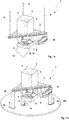
- FIGs. 1a and 1b are perspective depictions of a device 1 adapted to two basic types of use.
- the device 1 has a respective support element 2, embodied here as a triangular frame structure with a chamber 3 mounted in it and in this instance, a total of four manipulators 4, 5, 6, 7 attached to it.
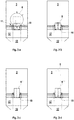
- the various tasks performed by these manipulators 4, 5, 6, 7 and their correspondingly adapted equipment will be discussed below with reference to, among others, the sequences of Figs. 2a - 2g and 4a - 4e .
- the manipulators 4, 5, 6, 7 are attached to the device 1 here. However, they can be separated from the device 1 establishing independent units that are only called on demand respectively.
- Figs. 1a and 1b differ essentially only with regard to the type of positioning over a previously detected UXO 8.
- the device 1 according to the exemplary embodiment in Fig. 1a is lowered in a manner not shown in detail here from an unmanned floater by means of three cables 9 in a shallow water region of up to approximately 50 m in depth and is held over the position of the UXO 8 in a stable fashion.
- a control team is located a sufficiently large distance away in order to perform monitoring- and possibly also control procedures.
- the people are always safe.
- the device 1 according to the exemplary embodiment in Fig. 1b is positioned by means of three legs 10 with only a suggested possibility of length adjustment ⁇ L, by means of which the support element 2 is positioned like a tripod over the detected UXO 8, which is lying isolated at a greater water depth, and the support element is leveled by means of a length compensation of at least one of the legs 10.
- the support element 2 is aligned essentially horizontally as part of a position correction.
- the device 1 according to Fig. 1b is connected via a cable to a manned supply ship, also not shown in detail, which is staffed with monitoring and control teams and, after the device 1 has been successfully positioned, is stationed remotely for the safety reasons mentioned previously.
- the cable in addition to a function for supplying the device with energy and operating supplies, which will be explained in detail below, and for waste disposal, the cable also serves as a mechanical positioning means and as a traction mechanism for raising and lowering the device 1 on board the supply ship, which is generally an oceangoing vessel.
- the chamber 3 is embodied as the actual centerpiece for a complete elimination of a UXO 8 without direct environmental harm.
- An upper tool is embodied as bell-shaped and has a large opening that is always oriented straight down toward a surface of a sea bottom BO. This opening is adjoined by a frame that can be lowered in a precisely vertical fashion, with an adapter 11 for accommodating the UXO 8.
- the chamber 3 is closed by means of a cover 12 that is mounted in pivoting fashion.
- the manipulator 4 is equipped with digging, cleaning, and/or suction means 13, which, with the use of imaging devices that are not shown in detail, are used to excavate the UXO 8 until it can be identified with regard to its design type and it is possible to exactly determine its spatial position and orientation.
- This step is very important simply because sunken moored mines, depending on their design, can have different types of detonation devices 14 distributed over different locations. And these detonation devices 14 can even be still so sensitive that merely touching one of these detonation devices 14 could cause the UXO 8 to explode.
- a mechanical state of the UXO 8 must also be investigated by means of the imaging devices of the manipulator 4, which have an ability beyond that of conventional optical camera processes, to reliably provide usable images under difficult conditions and despite a significant clouding of the surrounding water by the above-mentioned excavation and cleaning work.
- a sunken moored mine as the UXO 8 to be handled here must have a leak in an outer casing that otherwise serves as a float in order, due to the flooding of the float, to sink to the sea bottom.
- the manipulator 4 also has a device 15 for producing and definitely positioning, metering, and outputting a mechanical immobilization material.
- This immobilization material - in the form of liquefied paraffins, thermoplastic- or thermosetting plastics and foams, or cement - can be placed into the UXO 8 and/or around the UXO 8, even at least partially surrounding it.
- the above-mentioned substances After a certain amount of time, the above-mentioned substances have hardened to the point that they effectively prevent the UXO 8 from collapsing during the subsequent fastening and removal from the sea bottom by means of a gripper as an essential component of the manipulator 5 and are able to withstand this stress.
- a cement is advantageously used, which has the special feature that it can be adjusted by means of its composition so that it does not create any inherent buoyancy on the UXO 8 under water and adheres well, even to corroded metal.
- the still pasty cement does not dissolve in the surrounding seawater as it is being applied and also does not wash out.
- a manipulator 5 takes over from the previously active first manipulator 4 in the processing sequence. Consequently, the UXO 8 in Fig. 2b is embraced and lifted by a gripper 16 of the manipulator 5.
- This procedure is also monitored by means of imaging equipment on manipulator 4.
- the gripper 16 has cushioned inner surfaces, by means of which a force acting on the casing of the UXO 8 is distributed over comparatively large areas and is thus reduced as much as possible. At the same time, this reliably prevents the UXO 8 from slipping in the gripper 16 or even being dropped.
- the whole device 1 has been raised up by an amount ⁇ H. Thanks to this change in height ⁇ H above the surface BO of the sea bottom, it is now possible in the method step shown in Fig. 2d to open the chamber 3 by lowering a bottom part 17 of the chamber 3 without this part being able to touch the surface BO of the sea bottom or even another possibly adjacent UXO 8'.
- the bottom part 17 includes an internal receptacle 18 of the adapter 11.
- the gripper 16 is then pivoted by the manipulator 5 so that the UXO 8 assumes a predetermined orientation and correspondingly, after completion of the positioning, is transported by the manipulator 5 in the correct position into the corresponding receptacle 18 of the adapter 11 of the bottom part 17 and is accommodated therein, see Fig. 2e .
- the bottom part 17 is attached to the chamber 3 by means of a so-called Sarrus mechanism 19 by means of which the bottom part 17 is guided relative to the chamber 3 in a high-precision linear fashion.
- This precise linear guidance is considered necessary for a number of reasons: on the one hand, it must always be possible to reliably close the chamber 3 with the bottom part 17.
- Fig. 2f shows the device 1 in a closed state, i.e. one in which an opening of the chamber 3, which is oriented downward and toward the surface BO of the sea bottom, is securely closed by the bottom part 17.
- the UXO 8 is now exactly positioned on or in a receptacle 18 of the adapter 11 on the inside of the chamber 3. Then, the UXO 8 is removed from the water so to speak by pumping out and/or displacing the seawater contained in the chamber 3.
- a gas pressure prevailing in the chamber 3 thus essentially corresponds to the water pressure at this working depth.
- the device 1 is raised further out of the water or the sea.
- the third manipulator 6 is in use on the inside of the chamber 3.
- a metallic outer hull or casing of the UXO 8 is opened by means of water jet cutting with the addition of abrasives.
- An explosive contained in the UXO 8 is completely removed by using another tool employing liquefaction by means of water conveyed into the chamber 3 from the outside, i.e. likewise essentially by means of water jet cutting and rinsing.
- Components of the explosive are removed from the chamber 3 in an aqueous solution and/or in the form of sludge or suspension.
- this suspension is pumped out in order to be temporarily stored and/or disposed of separately outside the chamber 3, in this exemplary embodiment on the floater or some other supply unit at the surface of the water.
- Fig. 2h shows a scene out of the water, in which the scrap remaining in the chamber 3 is ejected by opening or pivoting the cover 12 while the bottom part 17 of the chamber 3 is lowered to release the adapter 11.
- the remaining metallic remnants can therefore fall out of the chamber 3 in order to be collected at the surface of the water on board a supply ship or the like. This assures that in addition to chemical impurities from explosive residues, metal parts are also prevented from falling back into the sea.
- the device 1 can be lowered directly back into the sea in order to dispose of the next UXO 8' and the above-described cycle begins again with a corresponding placement of the device 1 over a detected UXO 8'.
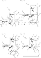
- FIG. 3a is a side view of a UXO 8 to be subsequently handled, which is embodied in the form of a moored mine that is oriented in a precisely vertical fashion and secured in a standardized receptacle 18 of the adapter 11.
- a moored mine of this kind taking into account the buoyancy under water, weighs approximately 400 kg, which must be securely grasped and moved by the 2 nd manipulator 5.
- a moored mine, as an essentially spherical body measures about 1.10 m in diameter and contains approximately 300 kg of explosives as a main charge and approximately 1 kg of explosive as a priming or booster charge.
- Fig. 3b shows a UXO 8 embodied in the form of a depth charge secured in another standardized receptacle 18 of the adapter 11.
- a depth charge with a weight of approximately 100 kg under water, has the outer form of a section of a cylinder with a diameter of approximately 50 cm and a length of 0.6 m.
- a depth charge contains approximately 140 kg of explosive as a main charge and approximately 1 kg of explosive as the main priming charge.
- FIGs. 3c and 3d show a holding of two parts of a bottom mine that has been pre-treated by being divided into thirds for subsequent handling with removal of the explosive, securing of the detonation devices, and final disposal of the remaining purely metallic remains.
- a bottom mine likewise constitutes a cylindrical section, which, with a diameter of approximately 50 cm corresponds to the diameter of a depth charge. It is thus possible to use the same adapter 11 in the bottom part 17 of the chamber 3 to accommodate both kinds of UXO 8.
- a bottom mine has an overall length of approximately 1.5 m.
- a bottom mine With a total weight of approximately 300 kg under water, a bottom mine contains a total weight of almost 350 kg of explosive as a main charge and approximately 4 kg of explosive in a priming charge.
- a bottom mine is dissected so that the individual pieces to be separated from the explosive correspond approximately to the dimensions of a depth charge.
- holders not shown in detail here, inside of the chamber 3, it is also possible to carry out a disarming and disposal of an entire bottom mine with sufficient positional securing to even prevent a tilting inside the chamber 3. This also prevents the explosive and cutting waste from escaping into the surrounding water during the severing process.
- the chamber 3 is in fact embodied as a pressure vessel in order, after one of the pieces of UXO 8 mentioned above by way of example has been received, to be able to ensure drainage in a compressed-air atmosphere, even at depths of approximately 50 m.
- a disarming of the UXO 8 however, always takes place by means of opening an outer casing and subsequently removing the explosive of at least one respective main charge by cutting and/or washing-out and transporting it in the form of a suspension out of the chamber 3.
- the possibility of an explosion occurring inside the chamber 3 is thus precluded as much as technically possible.
- the chamber 3 does not have to be embodied in the form of an explosion-protected explosion chamber, which would have to be able to withstand a detonation of 300 to 400 kg of TNT and explosives of this nature. Consequently, the chamber 3 essentially only has to be dimensioned with a view to the maximum use depth under water and the formats and outer dimensions of the UXO 8 to be accommodated therein. In addition, there must always be sufficient room inside the chamber 3 to accommodate the explosive/water suspension produced during the washing-out procedure as well as cut-off parts of the outer casing.
- water for cutting open and separating the outer casing and for washing out the explosive is supplied to the chamber 3 from the outside at high pressure, with or without the addition of additional abrasively acting substances, in this case, preferably from reservoirs on the support element 2.
- Waste water produced by these work procedures is continuously removed from the chamber 3 by means of a separate, closed circuit and is separately stored and/or prepared. Consequently, even as part of a dissection and washing-out procedure, no seawater can be contaminated with explosive and/or no metal parts of the bottom mine are left behind in the sea or get into the sea in the form of cuttings of the casing.
- Figs. 4a - 4e shows an above-described processing sequence once again.
- Fig. 4a shows a state after completion of the excavation of the UXO 8, at the transition from the above-described Fig. 1b to Fig. 1c .
- the gripper 16 has securely surrounded the UXO 8, which is possibly mechanically reinforced by means of cement, while the first manipulator 4 is already in a definite passive position on the frame 2.
- Fig. 4a shows a state after completion of the excavation of the UXO 8, at the transition from the above-described Fig. 1b to Fig. 1c .
- the gripper 16 has securely surrounded the UXO 8, which is possibly mechanically reinforced by means of cement, while the first manipulator 4 is already in a definite passive position on the frame 2.
- the device 1 has already completed the height change ⁇ H for the opening of the chamber 3 through a lowering of the bottom part 17 of the chamber 3 by means of a drive cylinder 20 in order to set the UXO 8 secured in the gripper 16 into a receptacle 18 of the adapter 11 in a defined orientation.
- This step has been completed in the illustration shown in Fig. 4c .
- the manipulator 5 also switches into a passive position so that the chamber 3 can be closed through the action of the Sarrus mechanism 19, see Fig. 4d .
- the water contained in the chamber 3 is pumped out or is pushed out through the introduction of compressed air so that an internal pressure in the chamber 3 is built up, which corresponds to a current water depth.
- a manipulator 7 for handling e.g. the at least one detonator 14 of the UXO 8
- the manipulators 6 and 7 assist each other in the delaboration like two hands, with the tasks of the cutting and washing out always remaining the duty of the manipulator 6.
- Image-producing monitoring devices e.g. in the form of camera systems and sensors inside the chamber 3, are not shown in the drawing.
- the explosive of a main charge contained in the UXO 8 is removed through liquefaction using separately supplied water, likewise essentially by means of water jet cutting carried out by the manipulator 6.
- the tool used for this purpose is correspondingly changed for the purpose of producing an aqueous suspension.
- the suspension produced is pumped out of the chamber 3 or is pushed out of the chamber by compressed air, through a separate drain valve, and into a closed disposal circuit.
- the chamber 3 is then cleansed of explosive residues by rinsing with water.
- the only things remaining inside the chamber 3 are the cut-off parts of the former casing of the UXO 8 and separately contained detonators 14, not shown in detail here.
- the manipulator 7 is provided inside the chamber 3 and, after the opening of the chamber 3, the manipulator 6 is provided in the outer region.
- Fig. 4e shows a process step in which now, through a simple pivoting of the cover 12 provided at the bottom by means of a drive cylinder 21, the remaining parts that have been cut off from the casing of the UXO 8 - as comparatively safe pieces metallic scrap 22, which have been cleansed of chemicals - are dumped out of the chamber 3 into a container that is not in the sea.
- the detonators 14, which generally contain comparatively small quantities of explosive, are separately removed from the chamber 3 and disposed of, provided that it was not possible for them to be correspondingly positioned by the manipulator 7 and cut open by the manipulator 6 and separated from the explosive contained therein by being washed out. In the latter case, these detonators 14 are also disposed of or recycled as metal scrap 22 of the outer casing of the UXO 8, without increased safety requirements.
- Fig. 5 is a top view of the frame-shaped support element 2 with the chamber 3 and manipulators 5, 6, 7, 8 affixed to it as well as drive units and the like of the Sarrus mechanism 19 of the bottom part 17 of the chamber 3.
- This design is identical in the exemplary embodiments shown in Figs. 1a and 1b .
- the variant according to Fig. 1a is used simply due to the basic lack of contact with the bottom.
- individual pieces of UXO 8 can be gradually removed, even from conglomerations, and disarmed and disposed of without additional stresses or contact resulting in an increased explosion danger.
- Autonomous units in the form of unmanned floaters with a high positioning precision with reference to geo-coordinates are available, which can maintain an exact depth position under water by means of winch systems, even when there are waves and when in shallow water regions.
- the above-described device 1 includes the chamber 3, which is embodied as a bell-shaped pressure hull that is open toward the sea bottom BO and that can be opened and closed in a definite way by means of a Sarrus mechanism 19.
- the chamber 3 is adapted to a series of different standard formats of large-format pieces of UXO 8 with correspondingly high contents of hazardous and environmentally harmful explosives and offers a correspondingly dimensioned open interior for accommodating them and supporting them in a mechanically stable fashion even during processing by means of manipulators 6, 7 provided inside the chamber, with accompanying image-based monitoring and/or lighting.
- the interior of the chamber 3 is also embodied for collecting and temporarily accommodating aqueous suspensions of abrasive substances and metallic pieces from the high-pressure water jet cutting and the washing-out of the explosive of a respective main charge of the UXO 8.
- the chamber 3 does not have to have any further mechanical reinforcement since the chamber 3 is in particular not embodied as a detonation chamber.
- External and internal safety systems prevent detonation of any UXO 8 or of any detonators, detonation devices 14, or bursting charges that have been severed from it.
- the chamber 3 also offers a unit that can be positioned and transported well, is of a manageable weight, and is of a size that can be maneuvered both under water at the surface of the water.
- a device 1 of the above-described type can be used as a compact, complete system for delaboration of even large-format pieces of UXO 8, which is not just for use in shallow marine regions and lakes.
- a device 1 can also be used on land, e.g. with positioning by means of a crane, for basically separating explosives and other parts of pieces of UXO 8 from the environment surrounding the chamber 3.
- Delaboration of UXO can be carried out with the greatest possible protection of people and the environment in pools of water e.g. below a ground water level, without excessive pumping-out, but also in a dry excavation pit.
- a device 1 that has been described in a number of embodiments therefore constitutes a universally usable tool, which can be used to a large extent independently of the weather, the day of the week, the time of day, the light conditions, etc. and can operate autonomously.
Landscapes
- Engineering & Computer Science (AREA)
- Aviation & Aerospace Engineering (AREA)
- Manufacturing & Machinery (AREA)
- General Engineering & Computer Science (AREA)
- Earth Drilling (AREA)
- Geophysics And Detection Of Objects (AREA)
- Farming Of Fish And Shellfish (AREA)
Priority Applications (1)
| Application Number | Priority Date | Filing Date | Title |
|---|---|---|---|
| PL17765091T PL3479052T3 (pl) | 2016-08-19 | 2017-08-18 | Sposób i urządzenie do usuwania elementów niewybuchów leżących pod wodą |
Applications Claiming Priority (2)
| Application Number | Priority Date | Filing Date | Title |
|---|---|---|---|
| DE102016115468.7A DE102016115468B4 (de) | 2016-08-19 | 2016-08-19 | Verfahren und Vorrichtung zur Entsorgung eines unter Wasser liegenden Kampfmittels |
| PCT/EP2017/070981 WO2018033643A1 (en) | 2016-08-19 | 2017-08-18 | Method and device for disposing of a piece of unexploded ordnance lying under water |
Publications (2)
| Publication Number | Publication Date |
|---|---|
| EP3479052A1 EP3479052A1 (en) | 2019-05-08 |
| EP3479052B1 true EP3479052B1 (en) | 2019-11-13 |
Family
ID=59856486
Family Applications (1)
| Application Number | Title | Priority Date | Filing Date |
|---|---|---|---|
| EP17765091.8A Active EP3479052B1 (en) | 2016-08-19 | 2017-08-18 | Method and device for disposing of a piece of unexploded ordnance lying under water |
Country Status (6)
| Country | Link |
|---|---|
| EP (1) | EP3479052B1 (da) |
| DE (1) | DE102016115468B4 (da) |
| DK (1) | DK3479052T3 (da) |
| LT (1) | LT3479052T (da) |
| PL (1) | PL3479052T3 (da) |
| WO (1) | WO2018033643A1 (da) |
Cited By (1)
| Publication number | Priority date | Publication date | Assignee | Title |
|---|---|---|---|---|
| WO2024154038A1 (en) * | 2023-01-18 | 2024-07-25 | Van Rompay Boudewijn Gabriel | Device for removing ammunition from the bottom of a water body and method applied thereby |
Families Citing this family (12)
| Publication number | Priority date | Publication date | Assignee | Title |
|---|---|---|---|---|
| NL2018969B1 (en) | 2017-05-23 | 2018-12-04 | Boskalis Bv Baggermaatschappij | Method and system for forming structures in fluid, especially under water |
| DE102018119339B4 (de) | 2018-08-08 | 2024-02-08 | Heinrich Hirdes Gmbh | Verfahren und Vorrichtung zum Entschärfen eines unter Wasser liegenden Blindgängers |
| WO2021207288A1 (en) * | 2020-04-06 | 2021-10-14 | Delta Subsea Llc | Underwater cut and capture system for submerged munitions |
| PL4222442T3 (pl) | 2020-10-01 | 2025-06-02 | Thyssenkrupp Marine Systems Gmbh | Mobilna komora do deelaboracji |
| DE102020212443A1 (de) | 2020-10-01 | 2022-04-07 | Thyssenkrupp Ag | Mobile Entschärfungskammer |
| DE102021205488A1 (de) * | 2021-05-31 | 2022-12-01 | Thyssenkrupp Ag | Vorrichtung zur sicheren Bergung und Transport von Kampfmitteln, insbesondere von unter Wasser gefundenen Kampfmitteln |
| DE102021208657A1 (de) | 2021-08-09 | 2023-02-09 | Atlas Elektronik Gmbh | Vorrichtung zur sicheren Bergung und Transport von Kampfmitteln, insbesondere von unter Wasser gefundenen Kampfmitteln |
| DE102021128441A1 (de) | 2021-11-02 | 2023-05-04 | EGGERS Kampfmittelbergung GmbH | Gerät zur Untersuchung und Bergung von Verdachtsobjekten im Unterwasserbereich |
| DE102022125485B3 (de) | 2022-10-04 | 2023-05-11 | Heinrich Hirdes Gmbh | Sprengverfahren und Sprengvorrichtung zur Beseitigung eines nicht explodierten Kampfmittels |
| DE102023101562A1 (de) | 2023-01-23 | 2024-07-25 | Thyssenkrupp Ag | Vorrichtung zur Bergung von Kampfmitteln |
| DE102023117504B3 (de) * | 2023-07-03 | 2024-11-21 | Thyssenkrupp Ag | Verwendung von Sprengstoff als Abrasivmittel beim Wasserstrahlschneiden |
| BE1032657B1 (nl) * | 2024-07-03 | 2026-03-19 | Van Rompay Boudewijn Gabriel | Verbeterde inrichting voor het verwijderen van munitie op de bodem van een watergebied |
Family Cites Families (6)
| Publication number | Priority date | Publication date | Assignee | Title |
|---|---|---|---|---|
| FR2684951A1 (fr) * | 1991-12-17 | 1993-06-18 | Eca | Procede de destruction d'un objet sous-marin, et notamment d'une mine immergee. |
| FR2722164B1 (fr) * | 1994-07-08 | 1996-09-13 | Eca | Procede perfectionne de destruction d'un objet sous-marin, notamment d'une mine immergee |
| US7363844B2 (en) * | 2006-03-15 | 2008-04-29 | James Barton | Remotely operated, underwater non-destructive ordnance recovery system and method |
| US7600460B2 (en) | 2006-05-09 | 2009-10-13 | Stephen M. Manders | On-site land mine removal system |
| DE102010033638A1 (de) * | 2010-08-06 | 2012-02-09 | Atlas Elektronik Gmbh | Kampfmittelräumgerät zum Räumen von Kampfmitteln, wie Seeminen, unter Wasser, unbemanntes Unterwasserfahrzeug mit derartigem Kampfmittelräumgerät sowie Verfahren hierzu |
| DE102013004445B3 (de) * | 2013-03-15 | 2014-05-22 | Frank Bargmann | Verfahren zum Bergen und Entschärfen von auf dem Meeresgrund liegenden Bomben |
-
2016
- 2016-08-19 DE DE102016115468.7A patent/DE102016115468B4/de active Active
-
2017
- 2017-08-18 LT LT17765091T patent/LT3479052T/lt unknown
- 2017-08-18 PL PL17765091T patent/PL3479052T3/pl unknown
- 2017-08-18 DK DK17765091.8T patent/DK3479052T3/da active
- 2017-08-18 WO PCT/EP2017/070981 patent/WO2018033643A1/en not_active Ceased
- 2017-08-18 EP EP17765091.8A patent/EP3479052B1/en active Active
Non-Patent Citations (1)
| Title |
|---|
| None * |
Cited By (1)
| Publication number | Priority date | Publication date | Assignee | Title |
|---|---|---|---|---|
| WO2024154038A1 (en) * | 2023-01-18 | 2024-07-25 | Van Rompay Boudewijn Gabriel | Device for removing ammunition from the bottom of a water body and method applied thereby |
Also Published As
| Publication number | Publication date |
|---|---|
| DE102016115468A1 (de) | 2018-02-22 |
| DE102016115468B4 (de) | 2021-03-04 |
| PL3479052T3 (pl) | 2020-04-30 |
| WO2018033643A1 (en) | 2018-02-22 |
| DK3479052T3 (da) | 2019-12-16 |
| LT3479052T (lt) | 2019-12-10 |
| EP3479052A1 (en) | 2019-05-08 |
Similar Documents
| Publication | Publication Date | Title |
|---|---|---|
| EP3479052B1 (en) | Method and device for disposing of a piece of unexploded ordnance lying under water | |
| US5574203A (en) | Process and installation for destroying munitions containing toxic agents | |
| US8807002B2 (en) | Weapon clearance appliance for clearing weapons, such as underwater mines, under water, unmanned underwater vehicle having a weapon clearance appliance of this kind, and method for this purpose | |
| US3822660A (en) | Method and apparatus for salvaging a sunken vessel | |
| US12228386B2 (en) | Mobile defusing chamber | |
| US9187161B2 (en) | Weapon clearance appliance for clearing weapons, such as underwater mines, under water, unmanned underwater vehicle having a weapon clearance appliance of this kind, and method for this purpose | |
| EP0749384B1 (fr) | Procede de recuperation d'une cargaison a bord d'une epave | |
| US12179895B2 (en) | Explosive container | |
| Koschinski et al. | Underwater unexploded ordnance–methods for a cetacean-friendly removal of explosives as alternatives to blasting | |
| Rowiński et al. | Toward safe and efficient recovery of gas munitions dumped at sea | |
| IE66751B1 (en) | Method and installation for the destruction of laboratory waste | |
| JPS5946836B2 (ja) | 水中航走体 | |
| KR101988225B1 (ko) | 선박의 유류 제거 방법 | |
| Schmit | Cut and capture system technology for demilitarization of underwater munitions | |
| WO1993022192A1 (en) | Device for salvaging objects on the seabed | |
| DE102021214012A1 (de) | Transportbehälter für die Bergung von Kampfmittelaltlasten unter Wasser und Verfahren | |
| RU2521070C2 (ru) | Надводная платформа для поднятия и обработки грузов со дна акватории, в том числе опасных | |
| GB2336804A (en) | A bomb disposal method | |
| Rowiński et al. | Cleaning the seas: proposal for use of remotely operated vehicle system to safely recover chemical weapons dumped in the early 20th century | |
| US12460913B2 (en) | Cut-and-capture systems for demilitarization of underwater munitions | |
| WO2012051604A2 (en) | Underwater neutralization system | |
| WO2013176562A1 (en) | Abovewater platform to lift objects from water area bed and process loads, including dangerous objects | |
| RU2679382C1 (ru) | Мобильная спасательная система | |
| CN116255879A (zh) | 用于水下未爆弹的激光抵近排除系统及其工作方法 | |
| RU2154802C1 (ru) | Способ разрушения бронетанковой техники |
Legal Events
| Date | Code | Title | Description |
|---|---|---|---|
| STAA | Information on the status of an ep patent application or granted ep patent |
Free format text: STATUS: UNKNOWN |
|
| STAA | Information on the status of an ep patent application or granted ep patent |
Free format text: STATUS: THE INTERNATIONAL PUBLICATION HAS BEEN MADE |
|
| PUAI | Public reference made under article 153(3) epc to a published international application that has entered the european phase |
Free format text: ORIGINAL CODE: 0009012 |
|
| STAA | Information on the status of an ep patent application or granted ep patent |
Free format text: STATUS: REQUEST FOR EXAMINATION WAS MADE |
|
| 17P | Request for examination filed |
Effective date: 20190130 |
|
| AK | Designated contracting states |
Kind code of ref document: A1 Designated state(s): AL AT BE BG CH CY CZ DE DK EE ES FI FR GB GR HR HU IE IS IT LI LT LU LV MC MK MT NL NO PL PT RO RS SE SI SK SM TR |
|
| AX | Request for extension of the european patent |
Extension state: BA ME |
|
| GRAJ | Information related to disapproval of communication of intention to grant by the applicant or resumption of examination proceedings by the epo deleted |
Free format text: ORIGINAL CODE: EPIDOSDIGR1 |
|
| STAA | Information on the status of an ep patent application or granted ep patent |
Free format text: STATUS: GRANT OF PATENT IS INTENDED |
|
| GRAP | Despatch of communication of intention to grant a patent |
Free format text: ORIGINAL CODE: EPIDOSNIGR1 |
|
| DAV | Request for validation of the european patent (deleted) | ||
| DAX | Request for extension of the european patent (deleted) | ||
| INTG | Intention to grant announced |
Effective date: 20190724 |
|
| GRAS | Grant fee paid |
Free format text: ORIGINAL CODE: EPIDOSNIGR3 |
|
| GRAJ | Information related to disapproval of communication of intention to grant by the applicant or resumption of examination proceedings by the epo deleted |
Free format text: ORIGINAL CODE: EPIDOSDIGR1 |
|
| GRAL | Information related to payment of fee for publishing/printing deleted |
Free format text: ORIGINAL CODE: EPIDOSDIGR3 |
|
| STAA | Information on the status of an ep patent application or granted ep patent |
Free format text: STATUS: REQUEST FOR EXAMINATION WAS MADE |
|
| GRAR | Information related to intention to grant a patent recorded |
Free format text: ORIGINAL CODE: EPIDOSNIGR71 |
|
| STAA | Information on the status of an ep patent application or granted ep patent |
Free format text: STATUS: GRANT OF PATENT IS INTENDED |
|
| GRAA | (expected) grant |
Free format text: ORIGINAL CODE: 0009210 |
|
| STAA | Information on the status of an ep patent application or granted ep patent |
Free format text: STATUS: THE PATENT HAS BEEN GRANTED |
|
| INTC | Intention to grant announced (deleted) | ||
| AK | Designated contracting states |
Kind code of ref document: B1 Designated state(s): AL AT BE BG CH CY CZ DE DK EE ES FI FR GB GR HR HU IE IS IT LI LT LU LV MC MK MT NL NO PL PT RO RS SE SI SK SM TR |
|
| INTG | Intention to grant announced |
Effective date: 20191007 |
|
| REG | Reference to a national code |
Ref country code: AT Ref legal event code: REF Ref document number: 1202127 Country of ref document: AT Kind code of ref document: T Effective date: 20191115 Ref country code: CH Ref legal event code: EP |
|
| REG | Reference to a national code |
Ref country code: DE Ref legal event code: R096 Ref document number: 602017008751 Country of ref document: DE |
|
| REG | Reference to a national code |
Ref country code: IE Ref legal event code: FG4D |
|
| REG | Reference to a national code |
Ref country code: DK Ref legal event code: T3 Effective date: 20191210 |
|
| REG | Reference to a national code |
Ref country code: NL Ref legal event code: FP |
|
| REG | Reference to a national code |
Ref country code: EE Ref legal event code: FG4A Ref document number: E018478 Country of ref document: EE Effective date: 20191203 |
|
| PG25 | Lapsed in a contracting state [announced via postgrant information from national office to epo] |
Ref country code: SE Free format text: LAPSE BECAUSE OF FAILURE TO SUBMIT A TRANSLATION OF THE DESCRIPTION OR TO PAY THE FEE WITHIN THE PRESCRIBED TIME-LIMIT Effective date: 20191113 Ref country code: PT Free format text: LAPSE BECAUSE OF FAILURE TO SUBMIT A TRANSLATION OF THE DESCRIPTION OR TO PAY THE FEE WITHIN THE PRESCRIBED TIME-LIMIT Effective date: 20200313 Ref country code: GR Free format text: LAPSE BECAUSE OF FAILURE TO SUBMIT A TRANSLATION OF THE DESCRIPTION OR TO PAY THE FEE WITHIN THE PRESCRIBED TIME-LIMIT Effective date: 20200214 Ref country code: NO Free format text: LAPSE BECAUSE OF FAILURE TO SUBMIT A TRANSLATION OF THE DESCRIPTION OR TO PAY THE FEE WITHIN THE PRESCRIBED TIME-LIMIT Effective date: 20200213 Ref country code: BG Free format text: LAPSE BECAUSE OF FAILURE TO SUBMIT A TRANSLATION OF THE DESCRIPTION OR TO PAY THE FEE WITHIN THE PRESCRIBED TIME-LIMIT Effective date: 20200213 |
|
| PG25 | Lapsed in a contracting state [announced via postgrant information from national office to epo] |
Ref country code: IS Free format text: LAPSE BECAUSE OF FAILURE TO SUBMIT A TRANSLATION OF THE DESCRIPTION OR TO PAY THE FEE WITHIN THE PRESCRIBED TIME-LIMIT Effective date: 20200313 Ref country code: HR Free format text: LAPSE BECAUSE OF FAILURE TO SUBMIT A TRANSLATION OF THE DESCRIPTION OR TO PAY THE FEE WITHIN THE PRESCRIBED TIME-LIMIT Effective date: 20191113 Ref country code: RS Free format text: LAPSE BECAUSE OF FAILURE TO SUBMIT A TRANSLATION OF THE DESCRIPTION OR TO PAY THE FEE WITHIN THE PRESCRIBED TIME-LIMIT Effective date: 20191113 |
|
| PG25 | Lapsed in a contracting state [announced via postgrant information from national office to epo] |
Ref country code: AL Free format text: LAPSE BECAUSE OF FAILURE TO SUBMIT A TRANSLATION OF THE DESCRIPTION OR TO PAY THE FEE WITHIN THE PRESCRIBED TIME-LIMIT Effective date: 20191113 |
|
| PG25 | Lapsed in a contracting state [announced via postgrant information from national office to epo] |
Ref country code: ES Free format text: LAPSE BECAUSE OF FAILURE TO SUBMIT A TRANSLATION OF THE DESCRIPTION OR TO PAY THE FEE WITHIN THE PRESCRIBED TIME-LIMIT Effective date: 20191113 Ref country code: CZ Free format text: LAPSE BECAUSE OF FAILURE TO SUBMIT A TRANSLATION OF THE DESCRIPTION OR TO PAY THE FEE WITHIN THE PRESCRIBED TIME-LIMIT Effective date: 20191113 Ref country code: RO Free format text: LAPSE BECAUSE OF FAILURE TO SUBMIT A TRANSLATION OF THE DESCRIPTION OR TO PAY THE FEE WITHIN THE PRESCRIBED TIME-LIMIT Effective date: 20191113 |
|
| REG | Reference to a national code |
Ref country code: DE Ref legal event code: R097 Ref document number: 602017008751 Country of ref document: DE |
|
| REG | Reference to a national code |
Ref country code: AT Ref legal event code: MK05 Ref document number: 1202127 Country of ref document: AT Kind code of ref document: T Effective date: 20191113 |
|
| PG25 | Lapsed in a contracting state [announced via postgrant information from national office to epo] |
Ref country code: SK Free format text: LAPSE BECAUSE OF FAILURE TO SUBMIT A TRANSLATION OF THE DESCRIPTION OR TO PAY THE FEE WITHIN THE PRESCRIBED TIME-LIMIT Effective date: 20191113 Ref country code: SM Free format text: LAPSE BECAUSE OF FAILURE TO SUBMIT A TRANSLATION OF THE DESCRIPTION OR TO PAY THE FEE WITHIN THE PRESCRIBED TIME-LIMIT Effective date: 20191113 |
|
| PLBE | No opposition filed within time limit |
Free format text: ORIGINAL CODE: 0009261 |
|
| STAA | Information on the status of an ep patent application or granted ep patent |
Free format text: STATUS: NO OPPOSITION FILED WITHIN TIME LIMIT |
|
| 26N | No opposition filed |
Effective date: 20200814 |
|
| PG25 | Lapsed in a contracting state [announced via postgrant information from national office to epo] |
Ref country code: AT Free format text: LAPSE BECAUSE OF FAILURE TO SUBMIT A TRANSLATION OF THE DESCRIPTION OR TO PAY THE FEE WITHIN THE PRESCRIBED TIME-LIMIT Effective date: 20191113 |
|
| PG25 | Lapsed in a contracting state [announced via postgrant information from national office to epo] |
Ref country code: SI Free format text: LAPSE BECAUSE OF FAILURE TO SUBMIT A TRANSLATION OF THE DESCRIPTION OR TO PAY THE FEE WITHIN THE PRESCRIBED TIME-LIMIT Effective date: 20191113 |
|
| PG25 | Lapsed in a contracting state [announced via postgrant information from national office to epo] |
Ref country code: MC Free format text: LAPSE BECAUSE OF FAILURE TO SUBMIT A TRANSLATION OF THE DESCRIPTION OR TO PAY THE FEE WITHIN THE PRESCRIBED TIME-LIMIT Effective date: 20191113 |
|
| REG | Reference to a national code |
Ref country code: CH Ref legal event code: PL |
|
| PG25 | Lapsed in a contracting state [announced via postgrant information from national office to epo] |
Ref country code: CH Free format text: LAPSE BECAUSE OF NON-PAYMENT OF DUE FEES Effective date: 20200831 Ref country code: LU Free format text: LAPSE BECAUSE OF NON-PAYMENT OF DUE FEES Effective date: 20200818 Ref country code: LI Free format text: LAPSE BECAUSE OF NON-PAYMENT OF DUE FEES Effective date: 20200831 |
|
| PG25 | Lapsed in a contracting state [announced via postgrant information from national office to epo] |
Ref country code: IE Free format text: LAPSE BECAUSE OF NON-PAYMENT OF DUE FEES Effective date: 20200818 |
|
| PG25 | Lapsed in a contracting state [announced via postgrant information from national office to epo] |
Ref country code: TR Free format text: LAPSE BECAUSE OF FAILURE TO SUBMIT A TRANSLATION OF THE DESCRIPTION OR TO PAY THE FEE WITHIN THE PRESCRIBED TIME-LIMIT Effective date: 20191113 Ref country code: MT Free format text: LAPSE BECAUSE OF FAILURE TO SUBMIT A TRANSLATION OF THE DESCRIPTION OR TO PAY THE FEE WITHIN THE PRESCRIBED TIME-LIMIT Effective date: 20191113 Ref country code: CY Free format text: LAPSE BECAUSE OF FAILURE TO SUBMIT A TRANSLATION OF THE DESCRIPTION OR TO PAY THE FEE WITHIN THE PRESCRIBED TIME-LIMIT Effective date: 20191113 |
|
| PG25 | Lapsed in a contracting state [announced via postgrant information from national office to epo] |
Ref country code: MK Free format text: LAPSE BECAUSE OF FAILURE TO SUBMIT A TRANSLATION OF THE DESCRIPTION OR TO PAY THE FEE WITHIN THE PRESCRIBED TIME-LIMIT Effective date: 20191113 |
|
| PGFP | Annual fee paid to national office [announced via postgrant information from national office to epo] |
Ref country code: PL Payment date: 20240730 Year of fee payment: 8 |
|
| REG | Reference to a national code |
Ref country code: DE Ref legal event code: R082 Ref document number: 602017008751 Country of ref document: DE Representative=s name: SCHMIDT, AXEL, DIPL.-ING., DE |
|
| PGFP | Annual fee paid to national office [announced via postgrant information from national office to epo] |
Ref country code: NL Payment date: 20250821 Year of fee payment: 9 |
|
| PGFP | Annual fee paid to national office [announced via postgrant information from national office to epo] |
Ref country code: FI Payment date: 20250820 Year of fee payment: 9 |
|
| PGFP | Annual fee paid to national office [announced via postgrant information from national office to epo] |
Ref country code: LT Payment date: 20250807 Year of fee payment: 9 Ref country code: DK Payment date: 20250821 Year of fee payment: 9 Ref country code: DE Payment date: 20250831 Year of fee payment: 9 |
|
| PGFP | Annual fee paid to national office [announced via postgrant information from national office to epo] |
Ref country code: IT Payment date: 20250829 Year of fee payment: 9 |
|
| PGFP | Annual fee paid to national office [announced via postgrant information from national office to epo] |
Ref country code: BE Payment date: 20250820 Year of fee payment: 9 Ref country code: GB Payment date: 20250818 Year of fee payment: 9 |
|
| PGFP | Annual fee paid to national office [announced via postgrant information from national office to epo] |
Ref country code: FR Payment date: 20250821 Year of fee payment: 9 |
|
| PGFP | Annual fee paid to national office [announced via postgrant information from national office to epo] |
Ref country code: EE Payment date: 20250901 Year of fee payment: 9 |
|
| PGFP | Annual fee paid to national office [announced via postgrant information from national office to epo] |
Ref country code: LV Payment date: 20250821 Year of fee payment: 9 |