EP3479025B1 - Injector assemblies configured to form a shielding flow of air injected into a combustion stage in a gas turbine engine - Google Patents
Injector assemblies configured to form a shielding flow of air injected into a combustion stage in a gas turbine engine Download PDFInfo
- Publication number
- EP3479025B1 EP3479025B1 EP16763394.0A EP16763394A EP3479025B1 EP 3479025 B1 EP3479025 B1 EP 3479025B1 EP 16763394 A EP16763394 A EP 16763394A EP 3479025 B1 EP3479025 B1 EP 3479025B1
- Authority
- EP
- European Patent Office
- Prior art keywords
- flow
- reactants
- injector assembly
- combustion
- passageway
- Prior art date
- Legal status (The legal status is an assumption and is not a legal conclusion. Google has not performed a legal analysis and makes no representation as to the accuracy of the status listed.)
- Active
Links
Images





Classifications
-
- F—MECHANICAL ENGINEERING; LIGHTING; HEATING; WEAPONS; BLASTING
- F23—COMBUSTION APPARATUS; COMBUSTION PROCESSES
- F23R—GENERATING COMBUSTION PRODUCTS OF HIGH PRESSURE OR HIGH VELOCITY, e.g. GAS-TURBINE COMBUSTION CHAMBERS
- F23R3/00—Continuous combustion chambers using liquid or gaseous fuel
- F23R3/28—Continuous combustion chambers using liquid or gaseous fuel characterised by the fuel supply
- F23R3/286—Continuous combustion chambers using liquid or gaseous fuel characterised by the fuel supply having fuel-air premixing devices
-
- F—MECHANICAL ENGINEERING; LIGHTING; HEATING; WEAPONS; BLASTING
- F23—COMBUSTION APPARATUS; COMBUSTION PROCESSES
- F23R—GENERATING COMBUSTION PRODUCTS OF HIGH PRESSURE OR HIGH VELOCITY, e.g. GAS-TURBINE COMBUSTION CHAMBERS
- F23R3/00—Continuous combustion chambers using liquid or gaseous fuel
- F23R3/005—Combined with pressure or heat exchangers
-
- F—MECHANICAL ENGINEERING; LIGHTING; HEATING; WEAPONS; BLASTING
- F23—COMBUSTION APPARATUS; COMBUSTION PROCESSES
- F23R—GENERATING COMBUSTION PRODUCTS OF HIGH PRESSURE OR HIGH VELOCITY, e.g. GAS-TURBINE COMBUSTION CHAMBERS
- F23R3/00—Continuous combustion chambers using liquid or gaseous fuel
- F23R3/002—Wall structures
-
- F—MECHANICAL ENGINEERING; LIGHTING; HEATING; WEAPONS; BLASTING
- F23—COMBUSTION APPARATUS; COMBUSTION PROCESSES
- F23R—GENERATING COMBUSTION PRODUCTS OF HIGH PRESSURE OR HIGH VELOCITY, e.g. GAS-TURBINE COMBUSTION CHAMBERS
- F23R3/00—Continuous combustion chambers using liquid or gaseous fuel
- F23R3/02—Continuous combustion chambers using liquid or gaseous fuel characterised by the air-flow or gas-flow configuration
- F23R3/04—Air inlet arrangements
- F23R3/045—Air inlet arrangements using pipes
-
- F—MECHANICAL ENGINEERING; LIGHTING; HEATING; WEAPONS; BLASTING
- F23—COMBUSTION APPARATUS; COMBUSTION PROCESSES
- F23R—GENERATING COMBUSTION PRODUCTS OF HIGH PRESSURE OR HIGH VELOCITY, e.g. GAS-TURBINE COMBUSTION CHAMBERS
- F23R3/00—Continuous combustion chambers using liquid or gaseous fuel
- F23R3/28—Continuous combustion chambers using liquid or gaseous fuel characterised by the fuel supply
- F23R3/34—Feeding into different combustion zones
-
- F—MECHANICAL ENGINEERING; LIGHTING; HEATING; WEAPONS; BLASTING
- F23—COMBUSTION APPARATUS; COMBUSTION PROCESSES
- F23R—GENERATING COMBUSTION PRODUCTS OF HIGH PRESSURE OR HIGH VELOCITY, e.g. GAS-TURBINE COMBUSTION CHAMBERS
- F23R3/00—Continuous combustion chambers using liquid or gaseous fuel
- F23R3/28—Continuous combustion chambers using liquid or gaseous fuel characterised by the fuel supply
- F23R3/34—Feeding into different combustion zones
- F23R3/346—Feeding into different combustion zones for staged combustion
-
- F—MECHANICAL ENGINEERING; LIGHTING; HEATING; WEAPONS; BLASTING
- F23—COMBUSTION APPARATUS; COMBUSTION PROCESSES
- F23R—GENERATING COMBUSTION PRODUCTS OF HIGH PRESSURE OR HIGH VELOCITY, e.g. GAS-TURBINE COMBUSTION CHAMBERS
- F23R3/00—Continuous combustion chambers using liquid or gaseous fuel
- F23R3/42—Continuous combustion chambers using liquid or gaseous fuel characterised by the arrangement or form of the flame tubes or combustion chambers
- F23R3/60—Support structures; Attaching or mounting means
-
- F—MECHANICAL ENGINEERING; LIGHTING; HEATING; WEAPONS; BLASTING
- F23—COMBUSTION APPARATUS; COMBUSTION PROCESSES
- F23R—GENERATING COMBUSTION PRODUCTS OF HIGH PRESSURE OR HIGH VELOCITY, e.g. GAS-TURBINE COMBUSTION CHAMBERS
- F23R2900/00—Special features of, or arrangements for continuous combustion chambers; Combustion processes therefor
- F23R2900/00018—Manufacturing combustion chamber liners or subparts
Definitions
- Disclosed embodiments are generally related to combustion turbine engines, such as gas turbine engines and, more particularly, to injector assemblies and/or a ducting arrangement including such injector assemblies, as may be used in a combustion system of a gas turbine engine.
- DCS distributed combustion system
- the inventors of the present invention have recognized certain issues that can arise in known distributed combustion systems (DCSs) where a number of injector assemblies may be disposed in a combustion stage (also referred to in the art as an axial combustion stage) that may be arranged axially downstream from a main combustion stage of the combustion system.
- DCSs distributed combustion systems
- a flow of reactants e.g., a mixture of fuel and air
- injector assemblies each may comprise an assembly of an air scoop and a fuel nozzle
- a decreased static temperature and a reduced combustion residence time each of which is conducive to reduce NOx emissions to be within acceptable levels at turbine inlet temperatures of approximately 1700°C (3200°F) and above.
- the downstream combustion stage may involve a ducting arrangement that passes a hot-temperature cross-flow of combustion products (e.g., vitiated gases from the main combustion stage) that in certain embodiments can reach relatively high subsonic speeds, which is conducive to further achieve a decreased static temperature and a reduced combustion residence time.
- combustion products e.g., vitiated gases from the main combustion stage
- the present inventors have recognized that the mixing performance provided by existing injector assemblies between the flow of reactants and the cross-flow of combustion products can benefit from further improvements. More particularly, the present inventors have recognized that the greater the amount of the cross-flow combustion products that can be entrained with the injected flow of reactants prior to ignition of the fuel contained in the injected flow of reactants, the lower the flame temperature will be, and thus the lower the amount of NOx emissions that will be produced.
- the present inventors propose an injector assembly according to claim 1 and designed to generate a shielding flow of air that surrounds the injected flow of reactants.
- This air-shielding effect transitorily separates the injected flow of reactants from the cross-flow of combustion products, thereby advantageously delaying ignition of the injected flow of reactants.
- This delayed ignition allows an incremental amount of cross-flow combustion products to entrain with the flow of reactants prior to stabilizing the flame formed in the downstream combustion stage.
- the present inventors have further recognized that in a traditional combustion system, cooling air that may be used for cooling certain components of the ducting arrangement is generally ejected into the vitiated cross-flow of combustion products, and is essentially lost, without contributing to the combustion process, which decreases the efficiency of the engine. Accordingly, the present inventors further propose to recapture the cooling air used for cooling such components so that recaptured cooling air is efficiently reutilized to generate the shielding flow of air.
- a disclosed ducting arrangement may comprise a unitized ducting arrangement.
- unitized in the context of this application, unless otherwise stated, refers to a structure which is formed as a single piece (e.g., monolithic construction) using a rapid manufacturing technology, such as without limitation, 3D Printing/Additive Manufacturing (AM) technologies, where the unitized structure, singly or in combination with other unitized structures, can form a component of the combustion turbine engine, such as for example respective injector assemblies, or an entire ducting arrangement including such assemblies.
- AM 3D Printing/Additive Manufacturing
- FIG. 1 is a simplified fragmentary schematic of a combustor system 10 (e.g., a DCS) for a combustion turbine engine, such as a gas turbine engine.
- a combustion stage e.g., the axial combustion stage
- the downstream combustion stage is fluidly coupled to receive (e.g., through a ducting arrangement 20, as may involve a number of transition ducts) a cross-flow of hot-temperature combustion products (schematically represented by arrow 21).
- injector assemblies 12 may be disposed in a combustor wall or transition duct having a conical section 17 configured to accelerate the cross-flow of combustion products.
- injector assemblies 12 may be disposed proximate the exit of the conical section of the combustor wall or transition duct. It will be appreciated that injector assemblies 12 are not limited to conical section 17.
- injector assemblies 12 may be disposed upstream of conical section 17.
- at least some of the array of injector assemblies 12 may be disposed at different axial locations to, for example, form two or more annular rows of injector assemblies 12.
- injector assembly 12 includes a reactant-guiding structure 16 arranged to convey a flow of reactants into the combustion stage (e.g., a mixture of fuel and air, schematically represented by arrow 19) for admixing with the cross-flow of combustion products.
- injector assembly 12 further includes means for injecting a flow of air (schematically represented by arrows 22 in FIG. 4 ) into the combustion stage. That is, an additional flow of air which at least initially does not admix with the flow of axial stage reactants 19.
- injector assembly 12 may have an injector assembly body comprising an inner wall 24 and an outer wall 25 that define a passageway 26 having an inlet side 27 and an outlet side 28.
- the passageway defined by inner wall 24 and outer wall 25 of the injector assembly body is effective to inject the flow of cooling fluid 22 (e.g., air) into the combustion stage.
- injector assembly 12 includes a plurality of circumferentially arranged openings 29 that may be fluidly coupled to an air plenum (not shown); or, as described in greater detail below, may be fluidly coupled to cooling fluid conduits in a combustor wall or transition duct.
- openings 29 are not limited to any particular shape. Thus, the shape illustrated in the drawings for openings 29 should not construed in a limiting sense.
- the flow of air 22 injected into the combustion stage may be conceptualized as effective to condition interaction (e.g., an air shielding effect) of the flow of reactants 19 with respect to the cross-flow of combustion products, as the flow of reactants is admitted into the combustion stage.
- condition interaction e.g., an air shielding effect
- FIG. 5 is a simplified schematic for conceptualizing the air shielding effect generated by air flow 22 injected by injector assembly 12.
- the air flow may be configured to surround the flow of reactants 19 injected by the injector assembly, as the flow of reactants is admitted in the combustion stage.
- This air shielding effect provides an ignition delay to the flow of reactants injected into the combustion stage and allows a relatively longer time interval for enhancing co-flow mixing (e.g., advective mixing) before the hot cross-flow of combustion products can ignite the flow of reactants.
- a flame 33 generated in the axial combustion stage is incrementally shifted farther downstream than would be the case, if the disclosed air shielding effect was not provided. That is, the shield of air flow surrounding the injected flow of reactants promotes liftoff and/or increases the liftoff distance of the flame, allowing a longer time interval for entrainment of the cross-flow with the injected flow of reactants and this reduces the flame temperature, which in turn reduces the level of NOx emissions.
- FIG. 6 is a cross-sectional, exploded view of one disclosed combustor wall 40' or transition duct body, such as may comprise a multi-panel arrangement 42, 44 that includes a plurality of cooling air conduits 46.
- FIG. 7 is a cross-sectional view of another disclosed combustor wall 40" or transition duct body, such as may comprise a unitized body 49 that includes the plurality of cooling air conduits 46.
- cooling air conduits 46 may be in flow communication with injector assembly 12 to recapture the cooling air that otherwise would be wasted to generate the shielding air flow, as shown in FIG. 11 . That is, this arrangement effectively makes dual usage of the air conveyed by cooling air conduits 46: use for cooling purposes of combustor structures; and use for combustion purposes in the axial stage.
- FIG. 8 is a fragmentary, isometric view of a combustor wall 40 or transition duct body (e.g., multi-panel arrangement, unitized body, etc.,) illustrating example locations 48 for interfacing with respective injector assemblies.
- FIG. 9 is a zoomed-in view of one such interface location 48 where one can see a plurality of outlets 52 for conveying cooling fluid (e.g., air) from a respective combustor wall 40 to a respective injector assembly 12 that may be disposed at the interface location, as seen in FIG. 10 .
- Each outlet 52 in the transition duct is positioned to be in correspondence with a respective one of the openings 29 at the inlet side of a respective injector assembly 12, partially seen in FIG.11 .
- the description below proceeds to describe various non-limiting embodiments that may be optionally implemented in disclosed injector assemblies.
- FIG. 12 is an isometric view that shows certain details in connection with the outlet side 28 of the passageway 26 constructed in an injector assembly 12.
- the outlet side 28 of passageway 26 comprises a varying cross-sectional profile along a perimeter of the outlet side so that, for example, a velocity and a volume of the injected flow of air can have a desired variation along the perimeter of the outlet side.
- the outlet side of the passageway may have a uniform cross-sectional profile, such as a circular profile.
- reactant-guiding structure 16 of injector assembly 12 may include means for swirling 56 the flow of reactants to be injected into the combustion stage.
- passageway 26 of injector assembly 12 may include means for swirling 58 the flow of cooling fluid to be injected into the combustion stage.
- the means for swirling 56, 58 may both be respectively included, depending on the needs of a given application.
- means for swirling 58 may be arranged to provide a swirl to the flow of cooling fluid along a first swirl direction, while the means for swirling 56 may be arranged to provide a swirl to the flow of reactants along a second swirl direction.
- the first and the second swirl directions may be arranged to provide equal swirling directions relative to one another, as shown in FIG. 15 . That is, the means for swirling 56, 58 may be arranged to provide co-swirling.
- the first and the second swirl directions may provide opposite swirling directions relative to one another, as shown in FIG. 16 . That is, the means for swirling 56, 58 may be arranged to provide counter-swirling.
- a number of orifices 62 may be arranged on the inner wall 24 of injector assembly 14 to provide fluid communication between passageway 26 and reactant-guiding structure 16.
- FIGs. 18-21 are respective bottom views of the respective flow outlets of an injector assembly 12 (such as outlet side 28 of passageway 26 that conveys the shielding air flow and the outlet 60 of reactant-guiding structure 16 that conveys the flow of reactants).
- injector assembly 12 such as outlet side 28 of passageway 26 that conveys the shielding air flow and the outlet 60 of reactant-guiding structure 16 that conveys the flow of reactants.
- the outlet side 28 of passageway 26 may include geometric features 64, such as a chevron arrangement, a lobe arrangement, serrated arrangement, etc., configured to promote co-flow intermixing of the flow of cooling fluid with the flow of reactants, as each flow is respectively admitted into the combustion stage.
- the outlet 60 of reactant-guiding structure 16 may include such geometric features 64.
- both the outlet side 28 of passageway 26 and the outlet 60 of reactant-guiding structure 16 can each include respective geometric features 64, as seen in FIG. 20 . If desired the respective geometric features 64 may be circumferentially staggered relative to one another as seen in FIG. 21 .
- FIG. 22 is a flow chart listing certain steps that may be used in a method for manufacturing disclosed ducting arrangements in a combustion system for a gas turbine engine.
- step 202 allows generating a computer-readable three-dimensional (3D) model, such as a computer aided design (CAD) model, of the ducting arrangement.
- the model defines a digital representation of the ducting arrangement, as described above in the context of the preceding figures.
- step 204 Prior to return step 206, allows manufacturing the ducting arrangement using an additive manufacturing technique in accordance with the generated three-dimensional model.
- Non-limiting examples of additive manufacturing techniques may include laser sintering, selective laser melting (SLM), direct metal laser sintering (DMLS), electron beam sintering (EBS), electron beam melting (EBM), etc.
- SLM selective laser melting
- DMLS direct metal laser sintering
- EBS electron beam sintering
- EBM electron beam melting
- FIG. 23 is a flow chart listing further steps that may be used in the disclosed method for manufacturing the ducting arrangement.
- manufacturing step 204 may include the following: after a start step 208, step 210 allows processing the model in a processor into a plurality of slices of data that define respective cross-sectional layers of the ducting arrangement. As described in step 212, at least some of the plurality of slices may define one or more voids within at least some of the respective cross-sectional layers of the ducting arrangement. (e.g., respective voids that may be used to form hollow portions of ducting arrangement 20, such as interface locations 48, cooling air conduits 46 and outlets 52 ( FIG.
- step 214 Prior to return step 216, step 214 allows successively forming each layer of the ducting arrangement by fusing a metallic powder using a suitable source of energy, such as without limitation, lasing energy or electron beam energy.
- a suitable source of energy such as without limitation, lasing energy or electron beam energy.
- FIG. 24 is a flow sequence in connection with a disclosed method for manufacturing a 3D object 232, such as ducting arrangement 20, injection assemblies 12, etc.
- a computer-readable three-dimensional (3D) model 224 such as a computer aided design (CAD) model, of the 3D object may be processed in a processor 226, where a slicing module 228 converts model 224 into a plurality of slice files (e.g., 2D data files) that defines respective cross-sectional layers of the 3D object.
- Processor 226 may be configured to control an additive manufacturing technique 230 used to make 3D object 232.
- the shield of air flow surrounding the flow of reactants is effective to promote liftoff and/or increases the liftoff distance of the flame generated in the downstream combustion stage allowing more time for entrainment of the cross-flow which reduces flame temperature and reduces NOx emissions; 2) autoignition flashback risk reduction and 3) the air flow that forms the shielding air additionally provides a cooling functionality, which maintains the hot side of the injector assembly body at a lower temperature thereby extending the life of the injector assembly.
- This cooling functionality allows for injector assemblies (e.g., scoops) that can benefit from a wide range of airflows with relatively similar cooling capability.
- the cooling in previous scoop designs was highly dependent on the total scoop flow, and thus limiting the range of airflows that could be used.
- disclosed embodiments are expected to be conducive to realizing a combustion system capable of achieving approximately a 65% combined cycle efficiency or greater in a gas turbine engine.
- Disclosed embodiments are also expected to realize a combustion system capable of maintaining stable operation at turbine inlet temperatures of approximately 1700° C and higher while maintaining a relatively low level of NOx emissions, and acceptable temperatures in components of the engine without an increase in cooling air consumption. By reusing for combustion purposes air that was previously limited just for cooling the combustor wall, one can enhance the efficiency of the combustion system while maintaining NOx emissions below regulatory limits.
Landscapes
- Engineering & Computer Science (AREA)
- Chemical & Material Sciences (AREA)
- Combustion & Propulsion (AREA)
- Mechanical Engineering (AREA)
- General Engineering & Computer Science (AREA)
- Turbine Rotor Nozzle Sealing (AREA)
Description
- This application claims benefit of the
August 3, 2016 filing date of US provisional application 62/370,289 - The present application is further related to US patent application (Attorney Docket 201607040) titled "Combustion System with Injector Assemblies Arranged to Recapture Cooling Air in a Combustor Wall to Form a Shielding Flow of Air in a Combustion Stage"; and US patent application (Attorney Docket 201614940) titled "Method And Computer-Readable Model For Additively Manufacturing Ducting Arrangement With Injector Assemblies Forming A Shielding Flow Of Air".
- Disclosed embodiments are generally related to combustion turbine engines, such as gas turbine engines and, more particularly, to injector assemblies and/or a ducting arrangement including such injector assemblies, as may be used in a combustion system of a gas turbine engine.
- In most large stationary gas turbine engines, fuel is delivered from a fuel source to a combustion section where the fuel is mixed with air and ignited to generate hot combustion products that define working gases. The working gases are directed to a turbine section where they drive the rotation of a turbine rotor. It is known that production of NOx emissions can be reduced by reducing the residence time of the working fluid in the combustion section. One approach to reduce this residence time is to provide and ignite a portion of the fuel and air downstream of the primary combustion stage. This approach is referred to in the art as a distributed combustion system (DCS). See, for example,
US patents 8,375,726 and8,752, 386 . - Document
US2014190170 discloses the preamble of claim 1. -
-
FIG. 1 is a fragmentary schematic of a disclosed ducting arrangement in a combustion system for a combustion turbine engine. The ducting arrangement can benefit from disclosed injector assemblies arranged to inject a respective flow of reactants in a combustion stage to be mixed with a cross-flow of combustion products. -
FIG. 2 is a cutaway view showing certain non-limiting structural details in connection with a disclosed injector assembly, which does not form part of the invention. -
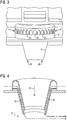
FIG. 3 is a side view of a disclosed injector assembly, which does not form part of the invention. -
FIG. 4 is a half-sectional view of a disclosed injector assembly showing a path for air flow through a passageway constructed in the injector assembly, which does not form part of the invention. -
FIG. 5 is a simplified schematic for conceptualizing an air shielding effect generated by air flow injected by a disclosed injector assembly, which does not form part of the invention. The air flow may be configured to surround the flow of reactants injected by the injector assembly, as the flow of reactants is admitted in the combustion stage. This shielding effect causes an ignition delay to the flow of reactants injected into the combustion stage and allows a relatively longer time interval for enhancing co-flow mixing before the hot cross-flow of combustion products can ignite the flow of reactants. -
FIG. 6 is a cross-sectional, exploded view of one disclosed combustor wall or any combustor component that conveys the combustion products through the combustor system, such as a transition duct, as may comprise a multi-panel arrangement that includes a plurality of cooling air conduits that may be in flow communication with a disclosed injector assembly to recapture the cooling air to generate the shielding air flow. -
FIG. 7 is a cross-sectional view of another disclosed combustor wall or any combustor component that conveys the combustion products through the combustor system, such as a transition duct, as may comprise a unitized body that includes the plurality of cooling air conduits. -
FIG. 8 is a fragmentary, isometric view of a disclosed combustor wall or any combustor component that conveys the combustion products through the combustor system, such as a transition duct, illustrating example locations for interfacing with respective disclosed injector assemblies. -
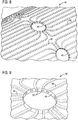
FIG. 9 is a zoomed-in view of one of the interface locations shown inFIG. 8 . -
FIG. 10 is a fragmentary, isometric view of an injector assembly disposed at the interface location shown inFIG. 9 . -
FIG. 11 is a fragmentary, cutaway isometric view showing further structural details of the injector assembly disposed at the location (shown inFIG. 9 ) for interfacing with a disclosed transition duct. -
FIG. 12 is an isometric view that shows non-limiting structural details in connection with the outlet side of the passageway constructed in the injector assembly according to the invention. -
FIGs. 13-17 are respective isometric views that show further non-limiting structural details in connection with disclosed injector assemblies which do not form part of the invention. -
FIGs. 18-21 are respective bottom views of disclosed injector assemblies that show further non-limiting structural details in connection with disclosed injector assemblies which do not form part of the invention. -
FIG. 22 is a flow chart listing certain steps that may be used in a method for manufacturing disclosed ducting arrangements. -
FIG. 23 is a flow chart listing further steps that may be used in the method for manufacturing disclosed ducting arrangements. -
FIG. 24 is a flow sequence in connection with the method for manufacturing disclosed ducting arrangements. - The inventors of the present invention have recognized certain issues that can arise in known distributed combustion systems (DCSs) where a number of injector assemblies may be disposed in a combustion stage (also referred to in the art as an axial combustion stage) that may be arranged axially downstream from a main combustion stage of the combustion system. For example, by injecting a flow of reactants (e.g., a mixture of fuel and air) through a number of injector assemblies (as each may comprise an assembly of an air scoop and a fuel nozzle) disposed in the combustion stage downstream from the main combustion stage, one can achieve a decreased static temperature and a reduced combustion residence time, each of which is conducive to reduce NOx emissions to be within acceptable levels at turbine inlet temperatures of approximately 1700°C (3200°F) and above.
- The downstream combustion stage may involve a ducting arrangement that passes a hot-temperature cross-flow of combustion products (e.g., vitiated gases from the main combustion stage) that in certain embodiments can reach relatively high subsonic speeds, which is conducive to further achieve a decreased static temperature and a reduced combustion residence time.
- The present inventors have recognized that the mixing performance provided by existing injector assemblies between the flow of reactants and the cross-flow of combustion products can benefit from further improvements. More particularly, the present inventors have recognized that the greater the amount of the cross-flow combustion products that can be entrained with the injected flow of reactants prior to ignition of the fuel contained in the injected flow of reactants, the lower the flame temperature will be, and thus the lower the amount of NOx emissions that will be produced.
- In view of such recognition, the present inventors propose an injector assembly according to claim 1 and designed to generate a shielding flow of air that surrounds the injected flow of reactants. This air-shielding effect transitorily separates the injected flow of reactants from the cross-flow of combustion products, thereby advantageously delaying ignition of the injected flow of reactants. This delayed ignition allows an incremental amount of cross-flow combustion products to entrain with the flow of reactants prior to stabilizing the flame formed in the downstream combustion stage.
- The present inventors have further recognized that in a traditional combustion system, cooling air that may be used for cooling certain components of the ducting arrangement is generally ejected into the vitiated cross-flow of combustion products, and is essentially lost, without contributing to the combustion process, which decreases the efficiency of the engine. Accordingly, the present inventors further propose to recapture the cooling air used for cooling such components so that recaptured cooling air is efficiently reutilized to generate the shielding flow of air.
- In the following detailed description, various specific details are set forth in order to provide a thorough understanding of such embodiments. However, those skilled in the art will understand that embodiments of the present invention may be practiced without these specific details, that the present invention is not limited to the depicted embodiments, and that the present invention may be practiced in a variety of alternative embodiments. In other instances, methods, procedures, and components, which would be well-understood by one skilled in the art have not been described in detail to avoid unnecessary and burdensome explanation.
- Furthermore, various operations may be described as multiple discrete steps performed in a manner that is helpful for understanding embodiments of the present invention. However, the order of description should not be construed as to imply that these operations need be performed in the order they are presented, nor that they are even order dependent, unless otherwise indicated. Moreover, repeated usage of the phrase "in one embodiment" does not necessarily refer to the same embodiment, although it may. It is noted that disclosed embodiments need not be construed as mutually exclusive embodiments, since aspects of such disclosed embodiments may be appropriately combined by one skilled in the art depending on the needs of a given application.
- The terms "comprising", "including", "having", and the like, as used in the present application, are intended to be synonymous unless otherwise indicated. Lastly, as used herein, the phrases "configured to" or "arranged to" embrace the concept that the feature preceding the phrases "configured to" or "arranged to" is intentionally and specifically designed or made to act or function in a specific way and should not be construed to mean that the feature just has a capability or suitability to act or function in the specified way, unless so indicated.
- In one non-limiting embodiment, a disclosed ducting arrangement may comprise a unitized ducting arrangement. The term "unitized" in the context of this application, unless otherwise stated, refers to a structure which is formed as a single piece (e.g., monolithic construction) using a rapid manufacturing technology, such as without limitation, 3D Printing/Additive Manufacturing (AM) technologies, where the unitized structure, singly or in combination with other unitized structures, can form a component of the combustion turbine engine, such as for example respective injector assemblies, or an entire ducting arrangement including such assemblies.
-
FIG. 1 is a simplified fragmentary schematic of a combustor system 10 (e.g., a DCS) for a combustion turbine engine, such as a gas turbine engine. In one non-limiting embodiment, an array of spaced-apart injector assemblies 12 may be circumferentially arranged in a combustion stage (e.g., the axial combustion stage) downstream from amain combustion stage 18 of the combustor system. The downstream combustion stage is fluidly coupled to receive (e.g., through aducting arrangement 20, as may involve a number of transition ducts) a cross-flow of hot-temperature combustion products (schematically represented by arrow 21). - As may be appreciated in
FIG. 1 , in one non-limiting embodiment,injector assemblies 12 may be disposed in a combustor wall or transition duct having aconical section 17 configured to accelerate the cross-flow of combustion products. In one non-limiting embodiment,injector assemblies 12 may be disposed proximate the exit of the conical section of the combustor wall or transition duct. It will be appreciated thatinjector assemblies 12 are not limited toconical section 17. For example, as may be further appreciated inFIG. 1 ,injector assemblies 12 may be disposed upstream ofconical section 17. In alternative embodiments, at least some of the array ofinjector assemblies 12 may be disposed at different axial locations to, for example, form two or more annular rows ofinjector assemblies 12. - As shown in
FIG. 2 , in one non-limiting embodiment,injector assembly 12 includes a reactant-guidingstructure 16 arranged to convey a flow of reactants into the combustion stage (e.g., a mixture of fuel and air, schematically represented by arrow 19) for admixing with the cross-flow of combustion products.Injector assembly 12 further includes means for injecting a flow of air (schematically represented byarrows 22 inFIG. 4 ) into the combustion stage. That is, an additional flow of air which at least initially does not admix with the flow ofaxial stage reactants 19. - As further shown in
FIG. 2 , in one non-limitingembodiment injector assembly 12 may have an injector assembly body comprising aninner wall 24 and anouter wall 25 that define apassageway 26 having aninlet side 27 and anoutlet side 28. The passageway defined byinner wall 24 andouter wall 25 of the injector assembly body is effective to inject the flow of cooling fluid 22 (e.g., air) into the combustion stage. - As may be appreciated in
FIG. 3 , in one non-limiting embodiment, at theinlet side 27 ofpassageway 26,injector assembly 12 includes a plurality of circumferentially arrangedopenings 29 that may be fluidly coupled to an air plenum (not shown); or, as described in greater detail below, may be fluidly coupled to cooling fluid conduits in a combustor wall or transition duct. It will be appreciated thatopenings 29 are not limited to any particular shape. Thus, the shape illustrated in the drawings foropenings 29 should not construed in a limiting sense. - Without limiting disclosed embodiments to any particular principle of operation, the flow of
air 22 injected into the combustion stage may be conceptualized as effective to condition interaction (e.g., an air shielding effect) of the flow ofreactants 19 with respect to the cross-flow of combustion products, as the flow of reactants is admitted into the combustion stage. -
FIG. 5 is a simplified schematic for conceptualizing the air shielding effect generated byair flow 22 injected byinjector assembly 12. The air flow may be configured to surround the flow ofreactants 19 injected by the injector assembly, as the flow of reactants is admitted in the combustion stage. This air shielding effect provides an ignition delay to the flow of reactants injected into the combustion stage and allows a relatively longer time interval for enhancing co-flow mixing (e.g., advective mixing) before the hot cross-flow of combustion products can ignite the flow of reactants. - In operation, a
flame 33 generated in the axial combustion stage is incrementally shifted farther downstream than would be the case, if the disclosed air shielding effect was not provided. That is, the shield of air flow surrounding the injected flow of reactants promotes liftoff and/or increases the liftoff distance of the flame, allowing a longer time interval for entrainment of the cross-flow with the injected flow of reactants and this reduces the flame temperature, which in turn reduces the level of NOx emissions. -
FIG. 6 is a cross-sectional, exploded view of one disclosed combustor wall 40' or transition duct body, such as may comprise amulti-panel arrangement air conduits 46.FIG. 7 is a cross-sectional view of another disclosedcombustor wall 40" or transition duct body, such as may comprise a unitizedbody 49 that includes the plurality of coolingair conduits 46. Regardless of the specific construction modality of the combustor wall or transition duct body, coolingair conduits 46 may be in flow communication withinjector assembly 12 to recapture the cooling air that otherwise would be wasted to generate the shielding air flow, as shown inFIG. 11 . That is, this arrangement effectively makes dual usage of the air conveyed by cooling air conduits 46: use for cooling purposes of combustor structures; and use for combustion purposes in the axial stage. -
FIG. 8 is a fragmentary, isometric view of acombustor wall 40 or transition duct body (e.g., multi-panel arrangement, unitized body, etc.,) illustratingexample locations 48 for interfacing with respective injector assemblies.FIG. 9 is a zoomed-in view of onesuch interface location 48 where one can see a plurality ofoutlets 52 for conveying cooling fluid (e.g., air) from arespective combustor wall 40 to arespective injector assembly 12 that may be disposed at the interface location, as seen inFIG. 10 . Eachoutlet 52 in the transition duct is positioned to be in correspondence with a respective one of theopenings 29 at the inlet side of arespective injector assembly 12, partially seen inFIG.11 . The description below proceeds to describe various non-limiting embodiments that may be optionally implemented in disclosed injector assemblies. -
FIG. 12 is an isometric view that shows certain details in connection with theoutlet side 28 of thepassageway 26 constructed in aninjector assembly 12. According to the invention, theoutlet side 28 ofpassageway 26 comprises a varying cross-sectional profile along a perimeter of the outlet side so that, for example, a velocity and a volume of the injected flow of air can have a desired variation along the perimeter of the outlet side. It will be appreciated that the outlet side of the passageway may have a uniform cross-sectional profile, such as a circular profile. - In one non-limiting embodiment, as seen in
FIG. 13 , reactant-guidingstructure 16 ofinjector assembly 12 may include means for swirling 56 the flow of reactants to be injected into the combustion stage. Alternatively, as seen inFIG. 14 ,passageway 26 ofinjector assembly 12 may include means for swirling 58 the flow of cooling fluid to be injected into the combustion stage. The means for swirling 56, 58 may both be respectively included, depending on the needs of a given application. - In one non-limiting embodiment, means for swirling 58 may be arranged to provide a swirl to the flow of cooling fluid along a first swirl direction, while the means for swirling 56 may be arranged to provide a swirl to the flow of reactants along a second swirl direction. In one non-limiting embodiment, the first and the second swirl directions may be arranged to provide equal swirling directions relative to one another, as shown in
FIG. 15 . That is, the means for swirling 56, 58 may be arranged to provide co-swirling. In another non-limiting embodiment, the first and the second swirl directions may provide opposite swirling directions relative to one another, as shown inFIG. 16 . That is, the means for swirling 56, 58 may be arranged to provide counter-swirling. - In one non-limiting embodiment, as seen in
FIG. 17 , a number oforifices 62 may be arranged on theinner wall 24 of injector assembly 14 to provide fluid communication betweenpassageway 26 and reactant-guidingstructure 16. -
FIGs. 18-21 are respective bottom views of the respective flow outlets of an injector assembly 12 (such asoutlet side 28 ofpassageway 26 that conveys the shielding air flow and theoutlet 60 of reactant-guidingstructure 16 that conveys the flow of reactants). - In one non-limiting embodiment, as seen in
FIG 18 , theoutlet side 28 ofpassageway 26 may includegeometric features 64, such as a chevron arrangement, a lobe arrangement, serrated arrangement, etc., configured to promote co-flow intermixing of the flow of cooling fluid with the flow of reactants, as each flow is respectively admitted into the combustion stage. - In another non-limiting embodiment, as seen in
FIG. 19 , theoutlet 60 of reactant-guidingstructure 16 may include such geometric features 64. Alternatively, both theoutlet side 28 ofpassageway 26 and theoutlet 60 of reactant-guidingstructure 16 can each include respectivegeometric features 64, as seen inFIG. 20 . If desired the respectivegeometric features 64 may be circumferentially staggered relative to one another as seen inFIG. 21 . -
FIG. 22 is a flow chart listing certain steps that may be used in a method for manufacturing disclosed ducting arrangements in a combustion system for a gas turbine engine. As shown inFIG. 22 , after astart step 200,step 202 allows generating a computer-readable three-dimensional (3D) model, such as a computer aided design (CAD) model, of the ducting arrangement. The model defines a digital representation of the ducting arrangement, as described above in the context of the preceding figures. Prior to returnstep 206,step 204 allows manufacturing the ducting arrangement using an additive manufacturing technique in accordance with the generated three-dimensional model. - Non-limiting examples of additive manufacturing techniques may include laser sintering, selective laser melting (SLM), direct metal laser sintering (DMLS), electron beam sintering (EBS), electron beam melting (EBM), etc. It will be appreciated that once a model has been generated, or otherwise available (e.g., loaded into a 3D digital printer, or loaded into a processor that controls the additive manufacturing technique), then manufacturing
step 204 need not be preceded by a generatingstep 202. It will be further appreciated that the entire ducting arrangement or one or more components of the ducting arrangement, e.g., transition duct, injector assembly, combination of transition duct with the injector assemblies, etc., may be formed as respective unitized structures using additive manufacturing in accordance with the generated three-dimensional model. -
FIG. 23 is a flow chart listing further steps that may be used in the disclosed method for manufacturing the ducting arrangement. In one non-limiting embodiment, manufacturing step 204 (FIG. 22 ) may include the following: after astart step 208,step 210 allows processing the model in a processor into a plurality of slices of data that define respective cross-sectional layers of the ducting arrangement. As described instep 212, at least some of the plurality of slices may define one or more voids within at least some of the respective cross-sectional layers of the ducting arrangement. (e.g., respective voids that may be used to form hollow portions ofducting arrangement 20, such asinterface locations 48, coolingair conduits 46 and outlets 52 (FIG. 9 ),passageway 26 andopenings 29 in connection withinjection assemblies 12, (FIG. 3 and FIG. 4 )). Prior to returnstep 216,step 214 allows successively forming each layer of the ducting arrangement by fusing a metallic powder using a suitable source of energy, such as without limitation, lasing energy or electron beam energy. -
FIG. 24 is a flow sequence in connection with a disclosed method for manufacturing a3D object 232, such asducting arrangement 20,injection assemblies 12, etc. A computer-readable three-dimensional (3D)model 224, such as a computer aided design (CAD) model, of the 3D object may be processed in aprocessor 226, where aslicing module 228converts model 224 into a plurality of slice files (e.g., 2D data files) that defines respective cross-sectional layers of the 3D object.Processor 226 may be configured to control anadditive manufacturing technique 230 used to make3D object 232. - In operation at least the following advantages are believed to be achieved by disclosed embodiments: 1) The shield of air flow surrounding the flow of reactants is effective to promote liftoff and/or increases the liftoff distance of the flame generated in the downstream combustion stage allowing more time for entrainment of the cross-flow which reduces flame temperature and reduces NOx emissions; 2) autoignition flashback risk reduction and 3) the air flow that forms the shielding air additionally provides a cooling functionality, which maintains the hot side of the injector assembly body at a lower temperature thereby extending the life of the injector assembly. This cooling functionality allows for injector assemblies (e.g., scoops) that can benefit from a wide range of airflows with relatively similar cooling capability. Opposite to disclosed embodiments, the cooling in previous scoop designs was highly dependent on the total scoop flow, and thus limiting the range of airflows that could be used. In operation, disclosed embodiments are expected to be conducive to realizing a combustion system capable of achieving approximately a 65% combined cycle efficiency or greater in a gas turbine engine. Disclosed embodiments are also expected to realize a combustion system capable of maintaining stable operation at turbine inlet temperatures of approximately 1700° C and higher while maintaining a relatively low level of NOx emissions, and acceptable temperatures in components of the engine without an increase in cooling air consumption. By reusing for combustion purposes air that was previously limited just for cooling the combustor wall, one can enhance the efficiency of the combustion system while maintaining NOx emissions below regulatory limits.
Claims (12)
- An injector assembly adapted to be disposed in a combustion stage of a combustion turbine engine, the combustion stage fluidly coupled to receive a cross-flow of combustion products (21), the injector assembly comprising:a reactant-guiding structure (16) arranged to convey a flow of reactants (19) to admix with the cross-flow of combustion products; andmeans for injecting (24, 25, 26) a flow of air (22) arranged to condition interaction of the flow of reactants with the cross-flow of combustion products,wherein the injector assembly is designed to generate a shielding flow of air (22) to form a boundary of air flow that surrounds the flow of reactants (19), as the flow of reactants is admitted in the combustion stage, wherein the boundary of air flow (22) that surrounds the flow of reactants (19) is effective to transitorily shield the flow of reactants conveyed to the combustion stage from the cross-flow of combustion products, and thus provide an ignition delay to the flow of reactants injected into the combustion stage,an injector assembly body comprising an inner wall (24) and an outer wall (25) that define a passageway (26) having an inlet side (27) and an outlet side (28), the passageway defined by the inner wall and the outer wall of the injector assembly body effective to inject the flow of air into the combustion stage,characterized in that the outlet side of the passageway comprises a varying cross-sectional profile along a perimeter of the outlet side of the passageway so that a velocity and a volume of the flow of air have a desired variation along the perimeter of the outlet side of the passageway.
- The injector assembly of claim 1, comprising an array of spaced apart injector assemblies configured to be circumferentially arranged in a transition duct, wherein at least some of the array of injector assemblies are configured to be disposed at different axial locations in the transition duct.
- The injector assembly of claim 1, wherein the outlet side of the passageway comprises geometric features (64) configured to promote co-flow intermixing of the flow of air with the flow of reactants, as each flow (19, 22) is respectively admitted into the combustion stage.
- The injector assembly of claim 1, wherein the passageway comprises means for swirling (58) the flow of cooling fluid to be injected into the combustion stage.
- The injector assembly of claim 1, wherein the reactant-guiding structure comprises means for swirling (56) the flow of reactants to be injected into the combustion stage.
- The injector assembly of claim 1, wherein the passageway comprises means for swirling (58) the flow of cooling fluid along a first swirl direction, wherein the reactant-guiding structure comprises means for swirling (56) the flow of reactants along a second swirl direction, wherein the first and the second swirl directions comprise equal or opposite swirling directions relative to one another.
- The injector assembly of claim 1, further comprising orifices (62) arranged on the inner wall of the injector assembly body to provide fluid communication between the passageway and the reactant-guiding structure.
- A ducting arrangement comprising:a combustor wall (40', 40") in a combustion stage of a combustion turbine engine, the combustion stage fluidly coupled to receive a cross-flow of combustion products (21);an injector assembly (12) of one of claims 1 to 7 disposed in the combustor wall, wherein the injector assembly includes the passageway (26) configured to inject the flow of air (22) arranged for conditioning interaction of the flow of reactants with the cross-flow of combustion products, the interaction conditioning based on a boundary formed by the flow of cooling fluid that surrounds the flow of reactants and is effective to provide an ignition delay to the flow of reactants injected into the combustion stage.
- The ducting arrangement of claim 8, wherein the combustor wall comprises a plurality of cooling fluid conduits (46) in fluid communication with the passageway (26) in the injector assembly to convey cooling fluid that passes through the plurality of cooling fluid conduits to the passageway and form the flow of cooling fluid to be injected.
- The ducting arrangement of claim 9, wherein the combustor wall comprises a multi-panel arrangement (42, 44) or a unitized structure (49).
- The ducting arrangement of claim 8, wherein the injection assembly comprises a unitized structure.
- The ducting arrangement of claim 8, comprising a unitized structure.
Applications Claiming Priority (2)
| Application Number | Priority Date | Filing Date | Title |
|---|---|---|---|
| US201662370289P | 2016-08-03 | 2016-08-03 | |
| PCT/US2016/048907 WO2018026382A1 (en) | 2016-08-03 | 2016-08-26 | Ducting arrangement with injector assemblies configured to form a shielding flow of air injected into a combustion stage in a gas turbine engine |
Publications (2)
| Publication Number | Publication Date |
|---|---|
| EP3479025A1 EP3479025A1 (en) | 2019-05-08 |
| EP3479025B1 true EP3479025B1 (en) | 2021-11-03 |
Family
ID=56894277
Family Applications (1)
| Application Number | Title | Priority Date | Filing Date |
|---|---|---|---|
| EP16763394.0A Active EP3479025B1 (en) | 2016-08-03 | 2016-08-26 | Injector assemblies configured to form a shielding flow of air injected into a combustion stage in a gas turbine engine |
Country Status (4)
| Country | Link |
|---|---|
| US (1) | US11029030B2 (en) |
| EP (1) | EP3479025B1 (en) |
| CN (1) | CN109563997B (en) |
| WO (1) | WO2018026382A1 (en) |
Cited By (1)
| Publication number | Priority date | Publication date | Assignee | Title |
|---|---|---|---|---|
| EP4276359A1 (en) | 2022-05-12 | 2023-11-15 | Siemens Energy Global GmbH & Co. KG | Fuel nozzle with multiple air passages |
Families Citing this family (15)
| Publication number | Priority date | Publication date | Assignee | Title |
|---|---|---|---|---|
| JP6584634B2 (en) * | 2015-07-24 | 2019-10-02 | シーメンス アクチエンゲゼルシヤフトSiemens Aktiengesellschaft | Gas turbine transition duct with delayed lean injection with reduced combustion residence time |
| US11181273B2 (en) * | 2016-09-27 | 2021-11-23 | Siemens Energy Global GmbH & Co. KG | Fuel oil axial stage combustion for improved turbine combustor performance |
| FR3081539B1 (en) * | 2018-05-23 | 2021-06-04 | Safran Aircraft Engines | TURBOMACHINE COMBUSTION CHAMBER BOTTOM |
| US11255543B2 (en) * | 2018-08-07 | 2022-02-22 | General Electric Company | Dilution structure for gas turbine engine combustor |
| US10941944B2 (en) | 2018-10-04 | 2021-03-09 | Raytheon Technologies Corporation | Consumable support structures for additively manufactured combustor components |
| US11248789B2 (en) | 2018-12-07 | 2022-02-15 | Raytheon Technologies Corporation | Gas turbine engine with integral combustion liner and turbine nozzle |
| US11085639B2 (en) * | 2018-12-27 | 2021-08-10 | Rolls-Royce North American Technologies Inc. | Gas turbine combustor liner with integral chute made by additive manufacturing process |
| US11079111B2 (en) * | 2019-04-29 | 2021-08-03 | Solar Turbines Incorporated | Air tube |
| KR102164620B1 (en) * | 2019-06-19 | 2020-10-12 | 두산중공업 주식회사 | Combustor and gas turbine including the same |
| US11959643B2 (en) * | 2021-06-07 | 2024-04-16 | General Electric Company | Combustor for a gas turbine engine |
| US12152777B2 (en) * | 2021-06-07 | 2024-11-26 | General Electric Company | Combustor for a gas turbine engine |
| EP4511597A1 (en) * | 2022-06-01 | 2025-02-26 | Siemens Energy Global GmbH & Co. KG | Combustor having secondary fuel injector |
| KR102720523B1 (en) * | 2022-06-30 | 2024-10-23 | 두산에너빌리티 주식회사 | Jet nozzle, combustor and gas turbine including same |
| JP7539532B2 (en) | 2022-08-24 | 2024-08-23 | 三菱重工業株式会社 | Combustor tube, combustor, and gas turbine |
| KR102756078B1 (en) * | 2022-12-06 | 2025-01-21 | 두산에너빌리티 주식회사 | Combustor and gas turbine comprising the same |
Family Cites Families (17)
| Publication number | Priority date | Publication date | Assignee | Title |
|---|---|---|---|---|
| US5749219A (en) * | 1989-11-30 | 1998-05-12 | United Technologies Corporation | Combustor with first and second zones |
| EP0895024B1 (en) * | 1993-07-30 | 2003-01-02 | United Technologies Corporation | Swirl mixer for a combustor |
| US20090255256A1 (en) * | 2008-04-11 | 2009-10-15 | General Electric Company | Method of manufacturing combustor components |
| US8375726B2 (en) | 2008-09-24 | 2013-02-19 | Siemens Energy, Inc. | Combustor assembly in a gas turbine engine |
| US8701418B2 (en) | 2009-01-07 | 2014-04-22 | General Electric Company | Late lean injection for fuel flexibility |
| US8545215B2 (en) * | 2010-05-17 | 2013-10-01 | General Electric Company | Late lean injection injector |
| US8752386B2 (en) | 2010-05-25 | 2014-06-17 | Siemens Energy, Inc. | Air/fuel supply system for use in a gas turbine engine |
| US8850819B2 (en) * | 2010-06-25 | 2014-10-07 | United Technologies Corporation | Swirler, fuel and air assembly and combustor |
| US8640463B2 (en) | 2011-06-28 | 2014-02-04 | United Technologies Corporation | Swirler for gas turbine engine fuel injector |
| WO2013043076A1 (en) * | 2011-09-22 | 2013-03-28 | General Electric Company | Combustor and method for supplying fuel to a combustor |
| US9151500B2 (en) * | 2012-03-15 | 2015-10-06 | General Electric Company | System for supplying a fuel and a working fluid through a liner to a combustion chamber |
| US9200808B2 (en) * | 2012-04-27 | 2015-12-01 | General Electric Company | System for supplying fuel to a late-lean fuel injector of a combustor |
| US9551492B2 (en) | 2012-11-30 | 2017-01-24 | General Electric Company | Gas turbine engine system and an associated method thereof |
| US20140174090A1 (en) * | 2012-12-21 | 2014-06-26 | General Electric Company | System for supplying fuel to a combustor |
| US9534790B2 (en) * | 2013-01-07 | 2017-01-03 | General Electric Company | Fuel injector for supplying fuel to a combustor |
| US20150198332A1 (en) * | 2014-01-16 | 2015-07-16 | General Electric Company | Channel defining fuel nozzle of combustion system |
| US9551490B2 (en) | 2014-04-08 | 2017-01-24 | General Electric Company | System for cooling a fuel injector extending into a combustion gas flow field and method for manufacture |
-
2016
- 2016-08-26 CN CN201680088257.4A patent/CN109563997B/en active Active
- 2016-08-26 US US16/316,470 patent/US11029030B2/en active Active
- 2016-08-26 WO PCT/US2016/048907 patent/WO2018026382A1/en not_active Ceased
- 2016-08-26 EP EP16763394.0A patent/EP3479025B1/en active Active
Cited By (3)
| Publication number | Priority date | Publication date | Assignee | Title |
|---|---|---|---|---|
| EP4276359A1 (en) | 2022-05-12 | 2023-11-15 | Siemens Energy Global GmbH & Co. KG | Fuel nozzle with multiple air passages |
| EP4276358A1 (en) | 2022-05-12 | 2023-11-15 | Siemens Energy Global GmbH & Co. KG | Fuel nozzle with multiple air passages |
| US12072102B2 (en) | 2022-05-12 | 2024-08-27 | Siemens Energy Global GmbH & Co. KG | Fuel nozzle with multiple air passages |
Also Published As
| Publication number | Publication date |
|---|---|
| EP3479025A1 (en) | 2019-05-08 |
| CN109563997B (en) | 2021-01-12 |
| US20190226680A1 (en) | 2019-07-25 |
| US11029030B2 (en) | 2021-06-08 |
| CN109563997A (en) | 2019-04-02 |
| WO2018026382A1 (en) | 2018-02-08 |
Similar Documents
| Publication | Publication Date | Title |
|---|---|---|
| US11029030B2 (en) | Ducting arrangement with injector assemblies configured to form a shielding flow of air injected into a combustion stage in a gas turbine engine | |
| EP3475617B1 (en) | Combustion system with injector assembly | |
| US10095218B2 (en) | Method and computer-readable model for additively manufacturing ducting arrangement with injector assemblies forming a shielding flow of air | |
| US10222066B2 (en) | Ducting arrangement with injector assemblies arranged in an expanding cross-sectional area of a downstream combustion stage in a gas turbine engine | |
| CA2720197C (en) | Swirlers and method of manufacturing | |
| EP3436746B1 (en) | Injector assembly and ducting arrangement including such injector assemblies in a combustion system for a gas turbine engine | |
| EP1605207B1 (en) | Thrust augmentor for gas turbine engines | |
| US20170260866A1 (en) | Ducting arrangement in a combustion system of a gas turbine engine | |
| EP2971970B1 (en) | Counter swirl doublet combustor | |
| JP2005114347A (en) | Gas turbine engine combustor and engineering method of the same | |
| US10215038B2 (en) | Method and computer-readable model for additively manufacturing ducting arrangement for a gas turbine engine | |
| JP2011242123A (en) | Late lean injection injector | |
| US20170284676A1 (en) | Method and computer-readable model for additively manufacturing injector assembly or ducting arrangement including such injector assemblies | |
| US20170261964A1 (en) | Method and computer-readable model for additively manufacturing ducting arrangement for a combustion system in a gas turbine engine | |
| WO2009126403A2 (en) | Swirlers and method of manufacturing | |
| KR20250162365A (en) | Axial fuel stage injector with axially elongated mixing chambers, and combustor and gt system including same |
Legal Events
| Date | Code | Title | Description |
|---|---|---|---|
| STAA | Information on the status of an ep patent application or granted ep patent |
Free format text: STATUS: THE INTERNATIONAL PUBLICATION HAS BEEN MADE |
|
| PUAI | Public reference made under article 153(3) epc to a published international application that has entered the european phase |
Free format text: ORIGINAL CODE: 0009012 |
|
| STAA | Information on the status of an ep patent application or granted ep patent |
Free format text: STATUS: REQUEST FOR EXAMINATION WAS MADE |
|
| 17P | Request for examination filed |
Effective date: 20190129 |
|
| AK | Designated contracting states |
Kind code of ref document: A1 Designated state(s): AL AT BE BG CH CY CZ DE DK EE ES FI FR GB GR HR HU IE IS IT LI LT LU LV MC MK MT NL NO PL PT RO RS SE SI SK SM TR |
|
| AX | Request for extension of the european patent |
Extension state: BA ME |
|
| DAV | Request for validation of the european patent (deleted) | ||
| DAX | Request for extension of the european patent (deleted) | ||
| RAP1 | Party data changed (applicant data changed or rights of an application transferred) |
Owner name: SIEMENS ENERGY GLOBAL GMBH & CO. KG |
|
| GRAP | Despatch of communication of intention to grant a patent |
Free format text: ORIGINAL CODE: EPIDOSNIGR1 |
|
| STAA | Information on the status of an ep patent application or granted ep patent |
Free format text: STATUS: GRANT OF PATENT IS INTENDED |
|
| INTG | Intention to grant announced |
Effective date: 20210629 |
|
| GRAS | Grant fee paid |
Free format text: ORIGINAL CODE: EPIDOSNIGR3 |
|
| GRAA | (expected) grant |
Free format text: ORIGINAL CODE: 0009210 |
|
| STAA | Information on the status of an ep patent application or granted ep patent |
Free format text: STATUS: THE PATENT HAS BEEN GRANTED |
|
| AK | Designated contracting states |
Kind code of ref document: B1 Designated state(s): AL AT BE BG CH CY CZ DE DK EE ES FI FR GB GR HR HU IE IS IT LI LT LU LV MC MK MT NL NO PL PT RO RS SE SI SK SM TR |
|
| REG | Reference to a national code |
Ref country code: GB Ref legal event code: FG4D |
|
| REG | Reference to a national code |
Ref country code: AT Ref legal event code: REF Ref document number: 1444279 Country of ref document: AT Kind code of ref document: T Effective date: 20211115 Ref country code: CH Ref legal event code: EP |
|
| REG | Reference to a national code |
Ref country code: DE Ref legal event code: R096 Ref document number: 602016065743 Country of ref document: DE |
|
| REG | Reference to a national code |
Ref country code: IE Ref legal event code: FG4D |
|
| REG | Reference to a national code |
Ref country code: LT Ref legal event code: MG9D |
|
| REG | Reference to a national code |
Ref country code: NL Ref legal event code: MP Effective date: 20211103 |
|
| REG | Reference to a national code |
Ref country code: AT Ref legal event code: MK05 Ref document number: 1444279 Country of ref document: AT Kind code of ref document: T Effective date: 20211103 |
|
| PG25 | Lapsed in a contracting state [announced via postgrant information from national office to epo] |
Ref country code: RS Free format text: LAPSE BECAUSE OF FAILURE TO SUBMIT A TRANSLATION OF THE DESCRIPTION OR TO PAY THE FEE WITHIN THE PRESCRIBED TIME-LIMIT Effective date: 20211103 Ref country code: LT Free format text: LAPSE BECAUSE OF FAILURE TO SUBMIT A TRANSLATION OF THE DESCRIPTION OR TO PAY THE FEE WITHIN THE PRESCRIBED TIME-LIMIT Effective date: 20211103 Ref country code: FI Free format text: LAPSE BECAUSE OF FAILURE TO SUBMIT A TRANSLATION OF THE DESCRIPTION OR TO PAY THE FEE WITHIN THE PRESCRIBED TIME-LIMIT Effective date: 20211103 Ref country code: BG Free format text: LAPSE BECAUSE OF FAILURE TO SUBMIT A TRANSLATION OF THE DESCRIPTION OR TO PAY THE FEE WITHIN THE PRESCRIBED TIME-LIMIT Effective date: 20220203 Ref country code: AT Free format text: LAPSE BECAUSE OF FAILURE TO SUBMIT A TRANSLATION OF THE DESCRIPTION OR TO PAY THE FEE WITHIN THE PRESCRIBED TIME-LIMIT Effective date: 20211103 |
|
| PG25 | Lapsed in a contracting state [announced via postgrant information from national office to epo] |
Ref country code: IS Free format text: LAPSE BECAUSE OF FAILURE TO SUBMIT A TRANSLATION OF THE DESCRIPTION OR TO PAY THE FEE WITHIN THE PRESCRIBED TIME-LIMIT Effective date: 20220303 Ref country code: SE Free format text: LAPSE BECAUSE OF FAILURE TO SUBMIT A TRANSLATION OF THE DESCRIPTION OR TO PAY THE FEE WITHIN THE PRESCRIBED TIME-LIMIT Effective date: 20211103 Ref country code: PT Free format text: LAPSE BECAUSE OF FAILURE TO SUBMIT A TRANSLATION OF THE DESCRIPTION OR TO PAY THE FEE WITHIN THE PRESCRIBED TIME-LIMIT Effective date: 20220303 Ref country code: PL Free format text: LAPSE BECAUSE OF FAILURE TO SUBMIT A TRANSLATION OF THE DESCRIPTION OR TO PAY THE FEE WITHIN THE PRESCRIBED TIME-LIMIT Effective date: 20211103 Ref country code: NO Free format text: LAPSE BECAUSE OF FAILURE TO SUBMIT A TRANSLATION OF THE DESCRIPTION OR TO PAY THE FEE WITHIN THE PRESCRIBED TIME-LIMIT Effective date: 20220203 Ref country code: NL Free format text: LAPSE BECAUSE OF FAILURE TO SUBMIT A TRANSLATION OF THE DESCRIPTION OR TO PAY THE FEE WITHIN THE PRESCRIBED TIME-LIMIT Effective date: 20211103 Ref country code: LV Free format text: LAPSE BECAUSE OF FAILURE TO SUBMIT A TRANSLATION OF THE DESCRIPTION OR TO PAY THE FEE WITHIN THE PRESCRIBED TIME-LIMIT Effective date: 20211103 Ref country code: HR Free format text: LAPSE BECAUSE OF FAILURE TO SUBMIT A TRANSLATION OF THE DESCRIPTION OR TO PAY THE FEE WITHIN THE PRESCRIBED TIME-LIMIT Effective date: 20211103 Ref country code: GR Free format text: LAPSE BECAUSE OF FAILURE TO SUBMIT A TRANSLATION OF THE DESCRIPTION OR TO PAY THE FEE WITHIN THE PRESCRIBED TIME-LIMIT Effective date: 20220204 Ref country code: ES Free format text: LAPSE BECAUSE OF FAILURE TO SUBMIT A TRANSLATION OF THE DESCRIPTION OR TO PAY THE FEE WITHIN THE PRESCRIBED TIME-LIMIT Effective date: 20211103 |
|
| PG25 | Lapsed in a contracting state [announced via postgrant information from national office to epo] |
Ref country code: SM Free format text: LAPSE BECAUSE OF FAILURE TO SUBMIT A TRANSLATION OF THE DESCRIPTION OR TO PAY THE FEE WITHIN THE PRESCRIBED TIME-LIMIT Effective date: 20211103 Ref country code: SK Free format text: LAPSE BECAUSE OF FAILURE TO SUBMIT A TRANSLATION OF THE DESCRIPTION OR TO PAY THE FEE WITHIN THE PRESCRIBED TIME-LIMIT Effective date: 20211103 Ref country code: RO Free format text: LAPSE BECAUSE OF FAILURE TO SUBMIT A TRANSLATION OF THE DESCRIPTION OR TO PAY THE FEE WITHIN THE PRESCRIBED TIME-LIMIT Effective date: 20211103 Ref country code: EE Free format text: LAPSE BECAUSE OF FAILURE TO SUBMIT A TRANSLATION OF THE DESCRIPTION OR TO PAY THE FEE WITHIN THE PRESCRIBED TIME-LIMIT Effective date: 20211103 Ref country code: DK Free format text: LAPSE BECAUSE OF FAILURE TO SUBMIT A TRANSLATION OF THE DESCRIPTION OR TO PAY THE FEE WITHIN THE PRESCRIBED TIME-LIMIT Effective date: 20211103 Ref country code: CZ Free format text: LAPSE BECAUSE OF FAILURE TO SUBMIT A TRANSLATION OF THE DESCRIPTION OR TO PAY THE FEE WITHIN THE PRESCRIBED TIME-LIMIT Effective date: 20211103 |
|
| REG | Reference to a national code |
Ref country code: DE Ref legal event code: R097 Ref document number: 602016065743 Country of ref document: DE |
|
| PLBE | No opposition filed within time limit |
Free format text: ORIGINAL CODE: 0009261 |
|
| STAA | Information on the status of an ep patent application or granted ep patent |
Free format text: STATUS: NO OPPOSITION FILED WITHIN TIME LIMIT |
|
| 26N | No opposition filed |
Effective date: 20220804 |
|
| PG25 | Lapsed in a contracting state [announced via postgrant information from national office to epo] |
Ref country code: AL Free format text: LAPSE BECAUSE OF FAILURE TO SUBMIT A TRANSLATION OF THE DESCRIPTION OR TO PAY THE FEE WITHIN THE PRESCRIBED TIME-LIMIT Effective date: 20211103 |
|
| PG25 | Lapsed in a contracting state [announced via postgrant information from national office to epo] |
Ref country code: SI Free format text: LAPSE BECAUSE OF FAILURE TO SUBMIT A TRANSLATION OF THE DESCRIPTION OR TO PAY THE FEE WITHIN THE PRESCRIBED TIME-LIMIT Effective date: 20211103 |
|
| PG25 | Lapsed in a contracting state [announced via postgrant information from national office to epo] |
Ref country code: MC Free format text: LAPSE BECAUSE OF FAILURE TO SUBMIT A TRANSLATION OF THE DESCRIPTION OR TO PAY THE FEE WITHIN THE PRESCRIBED TIME-LIMIT Effective date: 20211103 |
|
| REG | Reference to a national code |
Ref country code: CH Ref legal event code: PL |
|
| GBPC | Gb: european patent ceased through non-payment of renewal fee |
Effective date: 20220826 |
|
| PG25 | Lapsed in a contracting state [announced via postgrant information from national office to epo] |
Ref country code: LU Free format text: LAPSE BECAUSE OF NON-PAYMENT OF DUE FEES Effective date: 20220826 Ref country code: LI Free format text: LAPSE BECAUSE OF NON-PAYMENT OF DUE FEES Effective date: 20220831 Ref country code: CH Free format text: LAPSE BECAUSE OF NON-PAYMENT OF DUE FEES Effective date: 20220831 |
|
| REG | Reference to a national code |
Ref country code: BE Ref legal event code: MM Effective date: 20220831 |
|
| PG25 | Lapsed in a contracting state [announced via postgrant information from national office to epo] |
Ref country code: IT Free format text: LAPSE BECAUSE OF FAILURE TO SUBMIT A TRANSLATION OF THE DESCRIPTION OR TO PAY THE FEE WITHIN THE PRESCRIBED TIME-LIMIT Effective date: 20211103 |
|
| PG25 | Lapsed in a contracting state [announced via postgrant information from national office to epo] |
Ref country code: IE Free format text: LAPSE BECAUSE OF NON-PAYMENT OF DUE FEES Effective date: 20220826 Ref country code: FR Free format text: LAPSE BECAUSE OF NON-PAYMENT OF DUE FEES Effective date: 20220831 |
|
| PG25 | Lapsed in a contracting state [announced via postgrant information from national office to epo] |
Ref country code: BE Free format text: LAPSE BECAUSE OF NON-PAYMENT OF DUE FEES Effective date: 20220831 |
|
| PG25 | Lapsed in a contracting state [announced via postgrant information from national office to epo] |
Ref country code: GB Free format text: LAPSE BECAUSE OF NON-PAYMENT OF DUE FEES Effective date: 20220826 |
|
| P01 | Opt-out of the competence of the unified patent court (upc) registered |
Effective date: 20231222 |
|
| PG25 | Lapsed in a contracting state [announced via postgrant information from national office to epo] |
Ref country code: HU Free format text: LAPSE BECAUSE OF FAILURE TO SUBMIT A TRANSLATION OF THE DESCRIPTION OR TO PAY THE FEE WITHIN THE PRESCRIBED TIME-LIMIT; INVALID AB INITIO Effective date: 20160826 |
|
| PG25 | Lapsed in a contracting state [announced via postgrant information from national office to epo] |
Ref country code: CY Free format text: LAPSE BECAUSE OF FAILURE TO SUBMIT A TRANSLATION OF THE DESCRIPTION OR TO PAY THE FEE WITHIN THE PRESCRIBED TIME-LIMIT Effective date: 20211103 |
|
| PG25 | Lapsed in a contracting state [announced via postgrant information from national office to epo] |
Ref country code: MK Free format text: LAPSE BECAUSE OF FAILURE TO SUBMIT A TRANSLATION OF THE DESCRIPTION OR TO PAY THE FEE WITHIN THE PRESCRIBED TIME-LIMIT Effective date: 20211103 |
|
| PG25 | Lapsed in a contracting state [announced via postgrant information from national office to epo] |
Ref country code: MT Free format text: LAPSE BECAUSE OF FAILURE TO SUBMIT A TRANSLATION OF THE DESCRIPTION OR TO PAY THE FEE WITHIN THE PRESCRIBED TIME-LIMIT Effective date: 20211103 |
|
| PGFP | Annual fee paid to national office [announced via postgrant information from national office to epo] |
Ref country code: DE Payment date: 20250827 Year of fee payment: 10 |
|
| PG25 | Lapsed in a contracting state [announced via postgrant information from national office to epo] |
Ref country code: TR Free format text: LAPSE BECAUSE OF FAILURE TO SUBMIT A TRANSLATION OF THE DESCRIPTION OR TO PAY THE FEE WITHIN THE PRESCRIBED TIME-LIMIT Effective date: 20211103 |