EP3478956B1 - Raketenmotor mit zusammengesetztem divergierendem düsenabschnitt - Google Patents
Raketenmotor mit zusammengesetztem divergierendem düsenabschnitt Download PDFInfo
- Publication number
- EP3478956B1 EP3478956B1 EP17745807.2A EP17745807A EP3478956B1 EP 3478956 B1 EP3478956 B1 EP 3478956B1 EP 17745807 A EP17745807 A EP 17745807A EP 3478956 B1 EP3478956 B1 EP 3478956B1
- Authority
- EP
- European Patent Office
- Prior art keywords
- annular
- combustion chamber
- fastener
- nozzle
- mount
- Prior art date
- Legal status (The legal status is an assumption and is not a legal conclusion. Google has not performed a legal analysis and makes no representation as to the accuracy of the status listed.)
- Active
Links
Images



Classifications
-
- F—MECHANICAL ENGINEERING; LIGHTING; HEATING; WEAPONS; BLASTING
- F02—COMBUSTION ENGINES; HOT-GAS OR COMBUSTION-PRODUCT ENGINE PLANTS
- F02K—JET-PROPULSION PLANTS
- F02K9/00—Rocket-engine plants, i.e. plants carrying both fuel and oxidant therefor; Control thereof
- F02K9/97—Rocket nozzles
-
- F—MECHANICAL ENGINEERING; LIGHTING; HEATING; WEAPONS; BLASTING
- F02—COMBUSTION ENGINES; HOT-GAS OR COMBUSTION-PRODUCT ENGINE PLANTS
- F02K—JET-PROPULSION PLANTS
- F02K9/00—Rocket-engine plants, i.e. plants carrying both fuel and oxidant therefor; Control thereof
- F02K9/42—Rocket-engine plants, i.e. plants carrying both fuel and oxidant therefor; Control thereof using liquid or gaseous propellants
- F02K9/60—Constructional parts; Details not otherwise provided for
- F02K9/62—Combustion or thrust chambers
- F02K9/64—Combustion or thrust chambers having cooling arrangements
-
- F—MECHANICAL ENGINEERING; LIGHTING; HEATING; WEAPONS; BLASTING
- F02—COMBUSTION ENGINES; HOT-GAS OR COMBUSTION-PRODUCT ENGINE PLANTS
- F02K—JET-PROPULSION PLANTS
- F02K9/00—Rocket-engine plants, i.e. plants carrying both fuel and oxidant therefor; Control thereof
- F02K9/97—Rocket nozzles
- F02K9/972—Fluid cooling arrangements for nozzles
-
- F—MECHANICAL ENGINEERING; LIGHTING; HEATING; WEAPONS; BLASTING
- F05—INDEXING SCHEMES RELATING TO ENGINES OR PUMPS IN VARIOUS SUBCLASSES OF CLASSES F01-F04
- F05D—INDEXING SCHEME FOR ASPECTS RELATING TO NON-POSITIVE-DISPLACEMENT MACHINES OR ENGINES, GAS-TURBINES OR JET-PROPULSION PLANTS
- F05D2300/00—Materials; Properties thereof
- F05D2300/10—Metals, alloys or intermetallic compounds
-
- F—MECHANICAL ENGINEERING; LIGHTING; HEATING; WEAPONS; BLASTING
- F05—INDEXING SCHEMES RELATING TO ENGINES OR PUMPS IN VARIOUS SUBCLASSES OF CLASSES F01-F04
- F05D—INDEXING SCHEME FOR ASPECTS RELATING TO NON-POSITIVE-DISPLACEMENT MACHINES OR ENGINES, GAS-TURBINES OR JET-PROPULSION PLANTS
- F05D2300/00—Materials; Properties thereof
- F05D2300/60—Properties or characteristics given to material by treatment or manufacturing
- F05D2300/603—Composites; e.g. fibre-reinforced
Definitions
- the present invention relates to a nozzle comprising a combustion chamber made of metallic material and a composite material divergent formed by a cone-shaped wall, the composite material divergent being connected to the downstream end of the combustion chamber.
- thermostructural composite materials that is to say composite materials having mechanical properties which make them suitable for constituting structural elements and having the ability to retain these properties at elevated temperatures.
- thermostructural materials are in particular carbon/carbon or C/C composite materials (reinforcement made of carbon fibers and carbon matrix) and composite materials with a ceramic or CMC matrix, for example C/SiC (reinforcement made of carbon fibers and carbon matrix). silicon carbide), C/C-SiC (carbon fiber reinforcement and mixed carbon-silicon carbide matrix) or even SiC/SiC.
- the document US 2003/136128 discloses a nozzle having a metal combustion chamber downstream of which is connected a composite material divergent.
- the connection between the downstream end of the combustion chamber and the upstream end of the composite material divergent is made by means of a radial flange present on the upstream end of the divergent. More specifically, at its upstream end, the cone-shaped wall of the divergent is extended radially outwards by an annular portion of great thickness in order to form a radial flange allowing the passage of a clamping member for fixing the divergent in composite material on the downstream end of the combustion chamber.
- this attachment solution has the disadvantage of significantly increasing the manufacturing cost of the divergent due to the necessary presence of a portion of extra thickness in the composite material of the divergent and the additional machining of this portion to form the flange.
- the present invention proposes a nozzle having a longitudinal axis comprising a combustion chamber made of metallic material having a downstream end and a divergent part made of composite material formed of a cone-shaped wall extending between an upstream end and a downstream end, the upstream end of the diverging composite material being connected to the downstream end of the combustion chamber, characterized in that it further comprises an annular flange made of metallic material comprising a first part secured to the combustion chamber and a second part extending beyond the downstream end of the combustion chamber in the direction of the longitudinal axis of the nozzle and in that the upstream end of the divergent made of composite material is fixed to the second part of the annular flange by a plurality of clamping members each comprising a fixing screw, each fixing screw passing through the cone-shaped wall of the divergent mat composite material at the upstream end of said wall.
- the nozzle of the present invention comprises a composite material divergent, which makes it possible to significantly lighten the overall mass of the nozzle.
- the cone-shaped wall constituting the divergent is directly fixed to an axial flange fixed to the combustion chamber. It is therefore no longer necessary to produce a portion of extra thickness in the composite material of the divergent or to carry out specific machining operations for the formation of a flange in the divergent, which makes it possible to simplify the manufacture of the divergent with a single thin wall. (“near net shape”) and consequently reduce the manufacturing cost of the divergent.
- the manufacture of divergent according to the invention is further simplified and rationalized in that, thanks to their simple conical shape, the preforms intended to form the divergent can be easily stacked in the same densification furnace, which makes it possible to reduce the cost unit manufacturing of a nozzle.
- the combustion chamber comprises a cooling circuit in which a cooling fluid is intended to circulate, the cooling circuit comprising at least a first annular channel for the circulation of a cooling fluid. cooling extending along the downstream end of the combustion chamber and near the clamping members. The zone of the combustion chamber where the axial attachment with the divergent is made is thus cooled, which makes it possible to maintain the metal parts present in this zone at reasonable temperatures. Refractory metallic materials, such as the molybdenum alloy TZM, can thus be used for the clamping members.
- the combustion chamber comprises a cooling circuit in which the first annular channel for the circulation of a cooling fluid is present upstream of the clamping members and in which the cooling circuit cooling comprises a second annular channel for circulation of a cooling fluid extending along the free end of the second part of the annular flange, said second annular channel for circulation being present downstream of the clamping members.
- the zone of the combustion chamber and of the annular flange where the axial attachment with the divergent is made is thus cooled, which makes it possible to maintain the metal parts present in this zone at reasonable temperatures.
- the cooling circuit may further comprise a plurality of axial ducts communicating with the first and second annular channels, each axial duct being present between two adjacent clamping members.
- the cooling fluid circulates around the clamping members, which makes it possible to maintain the connection between the combustion chamber and the divergent at relatively low temperatures and to use refractory metallic materials, such as molybdenum alloy TZM, for clamping devices.
- the axial ducts communicating with the first and second annular channels are housed in stiffeners present on the external face of the nozzle.
- a seal is interposed between the inner face of the second part of the annular flange and the outer face of the wall of the divergent. This makes it possible to reinforce the seal between these two parts.
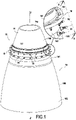
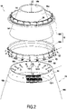
- the figure 1 and 2 illustrate a rocket engine nozzle 10 in accordance with one embodiment of the invention.
- the nozzle 10 of longitudinal axis ZZ' comprises a combustion chamber made of metallic material 14 having a downstream end 141 and a divergent 16 made of composite material formed of a cone-shaped wall 160 extending between an upstream end 161 and a downstream end 162, the upstream end 161 of the divergent 16 made of composite material being connected to the downstream end 141 of the combustion chamber 14.
- the nozzle 10 further comprises an annular flange 18 made of metallic material comprising a first part 181 integral with the combustion chamber 16 and a second part 182 extending beyond the downstream end 141 of the combustion chamber 14 in the direction of the longitudinal axis ZZ' of the nozzle 10.
- the upstream end 161 of the divergent 16 made of composite material is fixed to the second part 182 of the annular flange 18 by a plurality of clamping members 20 each comprising a fixing screw 21 and a nut 22, each fixing screw 21 passing through the cone-shaped wall 160 of the divergent 16 made of composite material at the level of the upstream end 161 of the wall 160.
- the first part 181 of the annular flange 18 is fixed to the outer face 14b of the combustion chamber by a metal/metal connection produced for example by brazing or welding.
- the second part 182 of the annular flange 18 is fixed to the wall 160 of the divergent 16 by clamping members 20 consisting here of a screw 21 and a nut 22.
- Each screw 21 has a conical head 210 which is housed in a countersink 1610 present on the internal face 16a of the wall 160 of the divergent 16, the rod 211 of the screw 21 passing through an orifice 1611 present in the wall 160 in the extension of the countersink 1610 and an orifice 1820 present in the second part 182 of the annular flange 18.
- a nut 22 is screwed onto the rod 211 on the side of the external face 182b of the second part 182 of the annular flange.
- an elastic washer 23 (or Belleville washer) can be interposed between the nut 22 and the external face 182b of the second part 182 of the annular flange 18 in order in particular to limit the stresses in the composite material of the wall 160 during the expansion of the clamping members 20 and of the second part 182.
- the second part 182 of the annular flange 18 is further fixed to the first part 181 of the annular flange 18 by clamping members 26 of the screw-nut type, the flange 18 thus forming a rigid connection between the combustion chamber 14 and the divergent 16.
- the downstream end 141 of the combustion chamber further comprises a cooling circuit 28 in which a cooling fluid is intended to circulate.
- the cooling circuit 28 here comprises an annular channel 280 for the circulation of a cooling fluid which extends along the downstream end 141 of the combustion chamber 14 and near the clamping members 20.
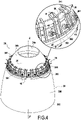
- FIG 4 and 5 illustrate another embodiment of a nozzle according to the invention which differs from the nozzle 10 described previously in particular in that the annular flange is made in the extension of the downstream end of the combustion chamber and in that the circuit cooling comprises several channels and ducts for circulation of a cooling fluid which extend around the clamping members.
- a nozzle 30 of a rocket engine and a longitudinal axis ZZ' comprises a combustion chamber 34 of metallic material having a downstream end 341 and a divergent 36 of composite material formed of a wall 360 in the shape of a cone extending between an upstream end 361 and a downstream end 362, the upstream end 361 of the divergent 36 made of composite material being connected to the downstream end 341 of the combustion chamber 34.
- the nozzle 30 further comprises an annular flange 38 made of metallic material comprising a first part 381 secured to the combustion chamber 16 and a second part 382 formed in the extension of the first part 381 and extending beyond the downstream end 341 of the combustion chamber 34 in the direction of the longitudinal axis ZZ' of the nozzle 30.
- the annular flange 38 is formed integrally with the combustion chamber 34.
- the upstream end 361 of the divergent 36 made of composite material is fixed to the second part 382 of the annular flange 38 by a plurality of clamping members 40 each comprising a fixing screw 41 and a nut 42, each fixing screw 41 passing through the cone-shaped wall 360 of the divergent 36 made of composite material at the level of the upstream end 361 of the wall 360.
- the second part 382 of the annular flange 38 is fixed to the wall 360 of the divergent 36 by clamping members 40 consisting here of a screw 41 and a nut 42.
- Each screw 41 has a conical head 410 which is housed in a countersink 3610 present on the internal face 36a of the wall 360 of the divergent 36, the rod 411 of the screw 41 passing through an orifice 3611 present in the wall 360 in the extension of the countersink 3610 and an orifice 3820 present in the second part 382 of the annular flange 38.
- a nut 42 is screwed onto the rod 411 on the side of the external face 382b of the second part 382 of the annular flange.
- an elastic washer 43 (or Belleville washer) can be interposed between the nut 42 and the outer face 382b of the second part 382 of the annular flange 38 in order in particular to limit the stresses in the composite material of the wall 360 during the expansion of the clamping members 40 and of the second part 382.
- a seal 44 for example in the form of a sheet of graphite, is interposed between the internal face 382a of the second part 382 of the annular flange 38 and the external face 36b of the wall 360 of the divergent 36 facing the second part 382.
- the flange 38 thus provides a rigid connection between the combustion chamber 34 and the divergent 36
- the downstream end 341 of the combustion chamber and the free end of the annular flange 18 further comprise a cooling circuit 48 in which a cooling fluid is intended to circulate.
- the cooling circuit 48 here comprises a first annular channel 480 for circulation of a cooling fluid present at the level of the downstream end 341 of the combustion chamber 34 upstream of the clamping members 40 and a second annular channel 481 for circulation of a cooling fluid which extends along the free end of the second part 382 of the annular flange 38, the second annular circulation channel 382 being present downstream of the clamping members 40.
- the cooling circuit 48 further comprises a plurality of axial ducts 482 communicating with the first and second annular channels 480 and 481. In the example described here, two axial ducts 482 are present between two adjacent clamping members 40 . Still in the example described here, the axial ducts are formed in stiffeners 50 present on the outer face of the nozzle 30.
- the attachment flanges 18 and 38 described above form a rigid connection between the downstream end of the combustion chamber made of metallic material and the upstream end of the divergent material. composite.
- the second part 182 or 382 of the annular fixing flange 18 or 38 is directly fixed on the upstream end 161 or 181 of the divergent 16 or 36, end having the shape of a truncated cone since it corresponds to a portion of the wall cone-shaped main wall of the divergent and not to an additional portion which extends radially outward from the main cone-shaped wall as in the document US 2003/136128 .
- Divergents 16 and 36 can also be made of carbon/carbon (C/C) composite material which, in known manner, is a material formed from a carbon fiber reinforcement densified by a carbon matrix and which can optionally be provided with of a coating such as for example a ceramic deposit (example SiC).
- C/C carbon/carbon
- the invention it is no longer necessary to make a portion of extra thickness in the composite material of the divergent for the formation of a flange in the divergent, which makes it possible to simplify the manufacture of the divergent with a single thin wall ( “near net shape”) and consequently reduce the manufacturing cost of the divergent.
- the preforms intended to form the divergent can be easily stacked in the same densification oven, as described in the documents US 2004/0071877 and US 2015/0152545 , which makes it possible to reduce the unit manufacturing cost of a nozzle.
Landscapes
- Engineering & Computer Science (AREA)
- Chemical & Material Sciences (AREA)
- Combustion & Propulsion (AREA)
- Mechanical Engineering (AREA)
- General Engineering & Computer Science (AREA)
- Turbine Rotor Nozzle Sealing (AREA)
- Portable Nailing Machines And Staplers (AREA)
Claims (9)
- Düse (10), die eine Längsachse (ZZ') aufweist, die eine Brennkammer (14) aus Metallmaterial, die ein stromabwärtiges Ende (141) aufweist, und eine Düsenerweiterung (16) aus Verbundmaterial umfasst, die aus einer kegelförmigen Wand (160) besteht, die sich zwischen einem stromaufwärtigen Ende (161) und einem stromabwärtigen Ende (162) erstreckt, wobei das stromaufwärtige Ende (161) der Düsenerweiterung aus Verbundmaterial mit dem stromabwärtigen Ende (141) der Brennkammer verbunden ist,
dadurch gekennzeichnet, dass sie ferner einen ringförmigen Befestigungsflansch (18) aus Metallmaterial umfasst, der einen ersten Teil (181), der fest mit der Brennkammer (14) verbunden ist, und einen zweiten Teil (182) umfasst, der sich über das stromabewärtige Ende (141) der Brennkammer (14) hinaus in der Richtung der Längsachse der Düse (10) erstreckt, wobei der erste und der zweite Teil des ringförmigen Befestigungsflansches auf starre Weise aneinander befestigt sind, und dadurch, dass das stromaufwärtige Ende (161) der Düsenerweiterung aus Verbundmaterial durch eine Vielzahl von Spannorganen (20), die jeweils eine Befestigungsschraube (21) umfassen, an dem zweiten Teil (182) des ringförmigen Befestigungsflansches (18) befestigt ist, wobei jede Befestigungsschraube die kegelförmige Wand (160) der Düsenerweiterung (16) aus Verbundmaterial im Bereich des stromaufwärtigen Endes (161) der Wand durchquert. - Düse nach Anspruch 1, wobei der zweite Teil (182) des ringförmigen Befestigungsflansches (18) durch Spannorgane (26) an dem ersten Teil (181) des ringförmigen Befestigungsflansches (18) befestigt ist.
- Düse nach Anspruch 1 oder 2, wobei die Brennkammer (14) einen Kühlkreis (28) umfasst, in dem ein Kühlfluid bestimmt ist, umzulaufen, wobei der Kühlkreis mindestens einen ersten ringförmigen Kanal (280) für den Umlauf eines Kühlfluids umfasst, der sich entlang des stromabwärtigen Endes (141) der Brennkammer (14) und in der Nähe der Spannorgane (20) erstreckt.
- Düse nach Anspruch 1, wobei der ringförmige Befestigungsflansch (38) einteilig mit der Brennkammer (34) gebildet ist, wobei der zweite Teil (382) des ringförmigen Befestigungsflansches (38) in der Verlängerung des ersten Teils (381) des Flansches gebildet ist.
- Düse nach Anspruch 4, wobei die Brennkammer (34) einen Kühlkreis umfasst, in dem ein Kühlfluid bestimmt ist, umzulaufen, wobei der Kühlkreis mindestens einen ersten ringförmigen Kanal (480) für den Umlauf eines Kühlfluids umfasst, der sich entlang des stromabwärtigen Endes (341) der Brennkammer (34) und in der Nähe der Spannorgane (40) erstreckt.
- Düse nach Anspruch 5, wobei die Brennkammer (34) einen Kühlkreis (48) umfasst, in dem der erste ringförmige Kanal (480) für den Umlauf eines Kühlfluids stromaufwärts der Spannorgane (40) vorhanden ist und wobei der Kühlkreis einen zweiten ringförmigen Kanal (481) für den Umlauf eines Kühlfluids umfasst, der sich entlang des freien Endes des zweiten Teils (382) des ringförmigen Flansches (38) erstreckt, wobei der zweite ringförmige Umlaufkanal stromabwärts der Spannorgane (40) vorhanden ist.
- Düse nach Anspruch 6, wobei der Kühlkreislauf (48) eine Vielzahl von axialen Leitungen (482) umfasst, die mit dem ersten und dem zweiten ringförmigen Kanal (480, 481) verbunden sind, wobei jede axiale Leitung (482) zwischen zwei benachbarten Spannorganen (40) vorhanden ist.
- Rohr nach Anspruch 7, wobei eine Vielzahl von Versteifungen (50) auf der Außenseite der Düse vorhanden sind, wobei die axialen Leitungen (482), die mit dem ersten und dem zweiten ringförmigen Kanal verbunden sind, in den Versteifungen (50) untergebracht sind.
- Rohr nach einem der Ansprüche 1 bis 8, wobei eine Dichtung (24) zwischen der Innenseite des zweiten Teils (182) des ringförmigen Flansches (18) und der Außenseite (16b) der Wand (160) der Düsenerweiterung angeordnet ist.
Applications Claiming Priority (2)
| Application Number | Priority Date | Filing Date | Title |
|---|---|---|---|
| FR1656095A FR3053403B1 (fr) | 2016-06-29 | 2016-06-29 | Moteur-fusee a divergent composite |
| PCT/FR2017/051730 WO2018002523A1 (fr) | 2016-06-29 | 2017-06-28 | Moteur-fusée a divergent composite |
Publications (2)
| Publication Number | Publication Date |
|---|---|
| EP3478956A1 EP3478956A1 (de) | 2019-05-08 |
| EP3478956B1 true EP3478956B1 (de) | 2022-05-04 |
Family
ID=57121295
Family Applications (1)
| Application Number | Title | Priority Date | Filing Date |
|---|---|---|---|
| EP17745807.2A Active EP3478956B1 (de) | 2016-06-29 | 2017-06-28 | Raketenmotor mit zusammengesetztem divergierendem düsenabschnitt |
Country Status (4)
| Country | Link |
|---|---|
| US (1) | US11035321B2 (de) |
| EP (1) | EP3478956B1 (de) |
| FR (1) | FR3053403B1 (de) |
| WO (1) | WO2018002523A1 (de) |
Families Citing this family (3)
| Publication number | Priority date | Publication date | Assignee | Title |
|---|---|---|---|---|
| US11028802B2 (en) | 2016-11-14 | 2021-06-08 | Northrop Grumman Systems Corporation | Liquid rocket engine assemblies and related methods |
| EP3773640A1 (de) | 2018-04-05 | 2021-02-17 | Helmholtz Zentrum München - Deutsches Forschungszentrum für Gesundheit und Umwelt (GmbH) | Larvenzubereitung von heligmosomoides polygyrus bakeri sowie verfahren zur herstellung davon und verwendungen davon |
| FR3094414B1 (fr) | 2019-03-27 | 2021-04-09 | Arianegroup Sas | Tuyère équipée d’une couronne thermo-régulée |
Family Cites Families (8)
| Publication number | Priority date | Publication date | Assignee | Title |
|---|---|---|---|---|
| FR2699970B1 (fr) * | 1992-12-30 | 1995-03-17 | Europ Propulsion | Dispositif de liaison glissante entre deux pièces soumises à de fortes sollicitations mécaniques et thermiques. |
| FR2821859B1 (fr) | 2001-03-06 | 2004-05-14 | Snecma Moteurs | Procede pour la densification par infiltration chimique en phase vapeur de substrats poreux ayant un passage central |
| DE10157752B4 (de) * | 2001-11-27 | 2006-04-06 | Eads Space Transportation Gmbh | Düsenverlängerung |
| US8281603B2 (en) * | 2008-08-11 | 2012-10-09 | United Technologies Corporation | Fastener assembly for connecting rocket engine nozzles |
| DE102011011220A1 (de) * | 2011-02-15 | 2012-08-16 | Astrium Gmbh | Raketentriebwerk mit einer ausfahrbaren Düsenerweiterung |
| FR2993044B1 (fr) | 2012-07-04 | 2014-08-08 | Herakles | Dispositif de chargement et installation pour la densification de preformes poreuses tronconiques et empilables |
| FR3008139B1 (fr) * | 2013-07-04 | 2015-07-24 | Snecma | Dispositif et procede de liaison |
| FR3011884B1 (fr) * | 2013-10-16 | 2018-06-15 | Arianegroup Sas | Chambre de propulsion pour fusee et procede de fabrication d'une telle chambre |
-
2016
- 2016-06-29 FR FR1656095A patent/FR3053403B1/fr active Active
-
2017
- 2017-06-28 WO PCT/FR2017/051730 patent/WO2018002523A1/fr not_active Ceased
- 2017-06-28 EP EP17745807.2A patent/EP3478956B1/de active Active
- 2017-06-28 US US16/311,820 patent/US11035321B2/en active Active
Also Published As
| Publication number | Publication date |
|---|---|
| WO2018002523A1 (fr) | 2018-01-04 |
| US11035321B2 (en) | 2021-06-15 |
| US20190203662A1 (en) | 2019-07-04 |
| FR3053403A1 (fr) | 2018-01-05 |
| EP3478956A1 (de) | 2019-05-08 |
| FR3053403B1 (fr) | 2018-07-27 |
Similar Documents
| Publication | Publication Date | Title |
|---|---|---|
| EP1045971B1 (de) | Wärmetauscher aus verbundwerkstoff und dessen herstellungsverfahren | |
| EP2375045B1 (de) | Heckteileinheit, die mit flexiblen Verbindungen mit Anschlag ausgestattet ist | |
| EP1797310B1 (de) | Mischer für eine düse mit getrenntem durchfluss | |
| EP3325819B1 (de) | Anordnung über ein mechanisches gestänge mit mindestens einem teil aus einem verbundwerkstoff | |
| CA2911465C (fr) | Assemblage a liaison auto-serrante en temperature | |
| EP2129878B1 (de) | Vorrichtung und methode zur verbindung von bauteilen mit unterschiedlichen thermischen ausdehnungskoeffizienten. | |
| EP2831382B1 (de) | Baueinheit für das hinterteil eines flugzeugtriebwerks, zugehöriges flugzeugtriebwerk und flugzeug | |
| EP2132426A1 (de) | Cmc-mischer mit struktureller aussenverschalung | |
| WO2018002523A1 (fr) | Moteur-fusée a divergent composite | |
| FR2787514A1 (fr) | Propulseur | |
| FR3117257A1 (fr) | Panneau multicellulaire d’atténuation acoustique à hauteur variable | |
| WO2014013165A1 (fr) | Procede de brasage de pieces en materiau composite avec ancrage du joint de brasure | |
| EP0421865A1 (de) | Raketenbrennkammer | |
| WO2013060956A1 (fr) | Dispositif de fixation d'une pièce creuse | |
| EP3947951B1 (de) | Strahldüse mit einem thermisch regulierten ring | |
| WO2013121150A1 (fr) | Ensemble d'arriere-corps de moteur aeronautique a turbine a gaz | |
| FR3063231A1 (fr) | Element d'injection de gaz pour unite de craquage catalytique fluide et systeme de distribution de gaz equipe de cet element d'injection. | |
| FR3056256A1 (fr) | Moteur-fusee a divergent segmente | |
| WO2018154018A1 (fr) | Dispositif a element ceramique amovible pour l'introduction d'un liquide a l'interieur d'un injecteur, et injecteur correspondant | |
| FR2972368A1 (fr) | Injecteur pour le melange de deux ergols, comprenant au moins un element d'injection a structure tricoaxiale |
Legal Events
| Date | Code | Title | Description |
|---|---|---|---|
| STAA | Information on the status of an ep patent application or granted ep patent |
Free format text: STATUS: UNKNOWN |
|
| STAA | Information on the status of an ep patent application or granted ep patent |
Free format text: STATUS: THE INTERNATIONAL PUBLICATION HAS BEEN MADE |
|
| PUAI | Public reference made under article 153(3) epc to a published international application that has entered the european phase |
Free format text: ORIGINAL CODE: 0009012 |
|
| STAA | Information on the status of an ep patent application or granted ep patent |
Free format text: STATUS: REQUEST FOR EXAMINATION WAS MADE |
|
| 17P | Request for examination filed |
Effective date: 20181218 |
|
| AK | Designated contracting states |
Kind code of ref document: A1 Designated state(s): AL AT BE BG CH CY CZ DE DK EE ES FI FR GB GR HR HU IE IS IT LI LT LU LV MC MK MT NL NO PL PT RO RS SE SI SK SM TR |
|
| AX | Request for extension of the european patent |
Extension state: BA ME |
|
| DAV | Request for validation of the european patent (deleted) | ||
| DAX | Request for extension of the european patent (deleted) | ||
| STAA | Information on the status of an ep patent application or granted ep patent |
Free format text: STATUS: EXAMINATION IS IN PROGRESS |
|
| 17Q | First examination report despatched |
Effective date: 20201216 |
|
| GRAP | Despatch of communication of intention to grant a patent |
Free format text: ORIGINAL CODE: EPIDOSNIGR1 |
|
| STAA | Information on the status of an ep patent application or granted ep patent |
Free format text: STATUS: GRANT OF PATENT IS INTENDED |
|
| INTG | Intention to grant announced |
Effective date: 20211130 |
|
| RAP3 | Party data changed (applicant data changed or rights of an application transferred) |
Owner name: ARIANEGROUP SAS |
|
| GRAS | Grant fee paid |
Free format text: ORIGINAL CODE: EPIDOSNIGR3 |
|
| GRAA | (expected) grant |
Free format text: ORIGINAL CODE: 0009210 |
|
| STAA | Information on the status of an ep patent application or granted ep patent |
Free format text: STATUS: THE PATENT HAS BEEN GRANTED |
|
| AK | Designated contracting states |
Kind code of ref document: B1 Designated state(s): AL AT BE BG CH CY CZ DE DK EE ES FI FR GB GR HR HU IE IS IT LI LT LU LV MC MK MT NL NO PL PT RO RS SE SI SK SM TR |
|
| REG | Reference to a national code |
Ref country code: GB Ref legal event code: FG4D Free format text: NOT ENGLISH |
|
| REG | Reference to a national code |
Ref country code: CH Ref legal event code: EP |
|
| REG | Reference to a national code |
Ref country code: AT Ref legal event code: REF Ref document number: 1489275 Country of ref document: AT Kind code of ref document: T Effective date: 20220515 |
|
| REG | Reference to a national code |
Ref country code: DE Ref legal event code: R096 Ref document number: 602017056907 Country of ref document: DE |
|
| REG | Reference to a national code |
Ref country code: IE Ref legal event code: FG4D Free format text: LANGUAGE OF EP DOCUMENT: FRENCH |
|
| REG | Reference to a national code |
Ref country code: LT Ref legal event code: MG9D |
|
| REG | Reference to a national code |
Ref country code: NL Ref legal event code: MP Effective date: 20220504 |
|
| REG | Reference to a national code |
Ref country code: AT Ref legal event code: MK05 Ref document number: 1489275 Country of ref document: AT Kind code of ref document: T Effective date: 20220504 |
|
| PG25 | Lapsed in a contracting state [announced via postgrant information from national office to epo] |
Ref country code: SE Free format text: LAPSE BECAUSE OF FAILURE TO SUBMIT A TRANSLATION OF THE DESCRIPTION OR TO PAY THE FEE WITHIN THE PRESCRIBED TIME-LIMIT Effective date: 20220504 Ref country code: PT Free format text: LAPSE BECAUSE OF FAILURE TO SUBMIT A TRANSLATION OF THE DESCRIPTION OR TO PAY THE FEE WITHIN THE PRESCRIBED TIME-LIMIT Effective date: 20220905 Ref country code: NO Free format text: LAPSE BECAUSE OF FAILURE TO SUBMIT A TRANSLATION OF THE DESCRIPTION OR TO PAY THE FEE WITHIN THE PRESCRIBED TIME-LIMIT Effective date: 20220804 Ref country code: NL Free format text: LAPSE BECAUSE OF FAILURE TO SUBMIT A TRANSLATION OF THE DESCRIPTION OR TO PAY THE FEE WITHIN THE PRESCRIBED TIME-LIMIT Effective date: 20220504 Ref country code: LT Free format text: LAPSE BECAUSE OF FAILURE TO SUBMIT A TRANSLATION OF THE DESCRIPTION OR TO PAY THE FEE WITHIN THE PRESCRIBED TIME-LIMIT Effective date: 20220504 Ref country code: HR Free format text: LAPSE BECAUSE OF FAILURE TO SUBMIT A TRANSLATION OF THE DESCRIPTION OR TO PAY THE FEE WITHIN THE PRESCRIBED TIME-LIMIT Effective date: 20220504 Ref country code: GR Free format text: LAPSE BECAUSE OF FAILURE TO SUBMIT A TRANSLATION OF THE DESCRIPTION OR TO PAY THE FEE WITHIN THE PRESCRIBED TIME-LIMIT Effective date: 20220805 Ref country code: FI Free format text: LAPSE BECAUSE OF FAILURE TO SUBMIT A TRANSLATION OF THE DESCRIPTION OR TO PAY THE FEE WITHIN THE PRESCRIBED TIME-LIMIT Effective date: 20220504 Ref country code: ES Free format text: LAPSE BECAUSE OF FAILURE TO SUBMIT A TRANSLATION OF THE DESCRIPTION OR TO PAY THE FEE WITHIN THE PRESCRIBED TIME-LIMIT Effective date: 20220504 Ref country code: BG Free format text: LAPSE BECAUSE OF FAILURE TO SUBMIT A TRANSLATION OF THE DESCRIPTION OR TO PAY THE FEE WITHIN THE PRESCRIBED TIME-LIMIT Effective date: 20220804 Ref country code: AT Free format text: LAPSE BECAUSE OF FAILURE TO SUBMIT A TRANSLATION OF THE DESCRIPTION OR TO PAY THE FEE WITHIN THE PRESCRIBED TIME-LIMIT Effective date: 20220504 |
|
| PG25 | Lapsed in a contracting state [announced via postgrant information from national office to epo] |
Ref country code: RS Free format text: LAPSE BECAUSE OF FAILURE TO SUBMIT A TRANSLATION OF THE DESCRIPTION OR TO PAY THE FEE WITHIN THE PRESCRIBED TIME-LIMIT Effective date: 20220504 Ref country code: PL Free format text: LAPSE BECAUSE OF FAILURE TO SUBMIT A TRANSLATION OF THE DESCRIPTION OR TO PAY THE FEE WITHIN THE PRESCRIBED TIME-LIMIT Effective date: 20220504 Ref country code: LV Free format text: LAPSE BECAUSE OF FAILURE TO SUBMIT A TRANSLATION OF THE DESCRIPTION OR TO PAY THE FEE WITHIN THE PRESCRIBED TIME-LIMIT Effective date: 20220504 Ref country code: IS Free format text: LAPSE BECAUSE OF FAILURE TO SUBMIT A TRANSLATION OF THE DESCRIPTION OR TO PAY THE FEE WITHIN THE PRESCRIBED TIME-LIMIT Effective date: 20220904 |
|
| PG25 | Lapsed in a contracting state [announced via postgrant information from national office to epo] |
Ref country code: SM Free format text: LAPSE BECAUSE OF FAILURE TO SUBMIT A TRANSLATION OF THE DESCRIPTION OR TO PAY THE FEE WITHIN THE PRESCRIBED TIME-LIMIT Effective date: 20220504 Ref country code: SK Free format text: LAPSE BECAUSE OF FAILURE TO SUBMIT A TRANSLATION OF THE DESCRIPTION OR TO PAY THE FEE WITHIN THE PRESCRIBED TIME-LIMIT Effective date: 20220504 Ref country code: RO Free format text: LAPSE BECAUSE OF FAILURE TO SUBMIT A TRANSLATION OF THE DESCRIPTION OR TO PAY THE FEE WITHIN THE PRESCRIBED TIME-LIMIT Effective date: 20220504 Ref country code: EE Free format text: LAPSE BECAUSE OF FAILURE TO SUBMIT A TRANSLATION OF THE DESCRIPTION OR TO PAY THE FEE WITHIN THE PRESCRIBED TIME-LIMIT Effective date: 20220504 Ref country code: DK Free format text: LAPSE BECAUSE OF FAILURE TO SUBMIT A TRANSLATION OF THE DESCRIPTION OR TO PAY THE FEE WITHIN THE PRESCRIBED TIME-LIMIT Effective date: 20220504 Ref country code: CZ Free format text: LAPSE BECAUSE OF FAILURE TO SUBMIT A TRANSLATION OF THE DESCRIPTION OR TO PAY THE FEE WITHIN THE PRESCRIBED TIME-LIMIT Effective date: 20220504 |
|
| REG | Reference to a national code |
Ref country code: CH Ref legal event code: PL |
|
| REG | Reference to a national code |
Ref country code: DE Ref legal event code: R097 Ref document number: 602017056907 Country of ref document: DE |
|
| REG | Reference to a national code |
Ref country code: BE Ref legal event code: MM Effective date: 20220630 |
|
| PG25 | Lapsed in a contracting state [announced via postgrant information from national office to epo] |
Ref country code: MC Free format text: LAPSE BECAUSE OF FAILURE TO SUBMIT A TRANSLATION OF THE DESCRIPTION OR TO PAY THE FEE WITHIN THE PRESCRIBED TIME-LIMIT Effective date: 20220504 |
|
| REG | Reference to a national code |
Ref country code: DE Ref legal event code: R082 Ref document number: 602017056907 Country of ref document: DE Representative=s name: CBDL PATENTANWAELTE GBR, DE Ref country code: DE Ref legal event code: R082 Ref document number: 602017056907 Country of ref document: DE Representative=s name: CBDL PATENTANWAELTE EGBR, DE |
|
| PLBE | No opposition filed within time limit |
Free format text: ORIGINAL CODE: 0009261 |
|
| STAA | Information on the status of an ep patent application or granted ep patent |
Free format text: STATUS: NO OPPOSITION FILED WITHIN TIME LIMIT |
|
| PG25 | Lapsed in a contracting state [announced via postgrant information from national office to epo] |
Ref country code: AL Free format text: LAPSE BECAUSE OF FAILURE TO SUBMIT A TRANSLATION OF THE DESCRIPTION OR TO PAY THE FEE WITHIN THE PRESCRIBED TIME-LIMIT Effective date: 20220504 |
|
| 26N | No opposition filed |
Effective date: 20230207 |
|
| PG25 | Lapsed in a contracting state [announced via postgrant information from national office to epo] |
Ref country code: LU Free format text: LAPSE BECAUSE OF NON-PAYMENT OF DUE FEES Effective date: 20220628 Ref country code: LI Free format text: LAPSE BECAUSE OF NON-PAYMENT OF DUE FEES Effective date: 20220630 Ref country code: IE Free format text: LAPSE BECAUSE OF NON-PAYMENT OF DUE FEES Effective date: 20220628 Ref country code: CH Free format text: LAPSE BECAUSE OF NON-PAYMENT OF DUE FEES Effective date: 20220630 |
|
| PG25 | Lapsed in a contracting state [announced via postgrant information from national office to epo] |
Ref country code: SI Free format text: LAPSE BECAUSE OF FAILURE TO SUBMIT A TRANSLATION OF THE DESCRIPTION OR TO PAY THE FEE WITHIN THE PRESCRIBED TIME-LIMIT Effective date: 20220504 Ref country code: BE Free format text: LAPSE BECAUSE OF NON-PAYMENT OF DUE FEES Effective date: 20220630 |
|
| P01 | Opt-out of the competence of the unified patent court (upc) registered |
Effective date: 20230612 |
|
| PG25 | Lapsed in a contracting state [announced via postgrant information from national office to epo] |
Ref country code: HU Free format text: LAPSE BECAUSE OF FAILURE TO SUBMIT A TRANSLATION OF THE DESCRIPTION OR TO PAY THE FEE WITHIN THE PRESCRIBED TIME-LIMIT; INVALID AB INITIO Effective date: 20170628 |
|
| PG25 | Lapsed in a contracting state [announced via postgrant information from national office to epo] |
Ref country code: MK Free format text: LAPSE BECAUSE OF FAILURE TO SUBMIT A TRANSLATION OF THE DESCRIPTION OR TO PAY THE FEE WITHIN THE PRESCRIBED TIME-LIMIT Effective date: 20220504 Ref country code: CY Free format text: LAPSE BECAUSE OF FAILURE TO SUBMIT A TRANSLATION OF THE DESCRIPTION OR TO PAY THE FEE WITHIN THE PRESCRIBED TIME-LIMIT Effective date: 20220504 |
|
| PG25 | Lapsed in a contracting state [announced via postgrant information from national office to epo] |
Ref country code: MT Free format text: LAPSE BECAUSE OF FAILURE TO SUBMIT A TRANSLATION OF THE DESCRIPTION OR TO PAY THE FEE WITHIN THE PRESCRIBED TIME-LIMIT Effective date: 20220504 |
|
| PG25 | Lapsed in a contracting state [announced via postgrant information from national office to epo] |
Ref country code: BG Free format text: LAPSE BECAUSE OF FAILURE TO SUBMIT A TRANSLATION OF THE DESCRIPTION OR TO PAY THE FEE WITHIN THE PRESCRIBED TIME-LIMIT Effective date: 20220504 |
|
| PG25 | Lapsed in a contracting state [announced via postgrant information from national office to epo] |
Ref country code: BG Free format text: LAPSE BECAUSE OF FAILURE TO SUBMIT A TRANSLATION OF THE DESCRIPTION OR TO PAY THE FEE WITHIN THE PRESCRIBED TIME-LIMIT Effective date: 20220504 |
|
| PGFP | Annual fee paid to national office [announced via postgrant information from national office to epo] |
Ref country code: DE Payment date: 20250618 Year of fee payment: 9 |
|
| PGFP | Annual fee paid to national office [announced via postgrant information from national office to epo] |
Ref country code: GB Payment date: 20250618 Year of fee payment: 9 |
|
| PGFP | Annual fee paid to national office [announced via postgrant information from national office to epo] |
Ref country code: FR Payment date: 20250625 Year of fee payment: 9 |
|
| PGFP | Annual fee paid to national office [announced via postgrant information from national office to epo] |
Ref country code: IT Payment date: 20250624 Year of fee payment: 9 |
|
| PG25 | Lapsed in a contracting state [announced via postgrant information from national office to epo] |
Ref country code: TR Free format text: LAPSE BECAUSE OF FAILURE TO SUBMIT A TRANSLATION OF THE DESCRIPTION OR TO PAY THE FEE WITHIN THE PRESCRIBED TIME-LIMIT Effective date: 20220504 |