EP3477845B1 - Variable torque electric motor assembly - Google Patents
Variable torque electric motor assembly Download PDFInfo
- Publication number
- EP3477845B1 EP3477845B1 EP18201963.8A EP18201963A EP3477845B1 EP 3477845 B1 EP3477845 B1 EP 3477845B1 EP 18201963 A EP18201963 A EP 18201963A EP 3477845 B1 EP3477845 B1 EP 3477845B1
- Authority
- EP
- European Patent Office
- Prior art keywords
- electric motor
- assembly
- rotor assembly
- primary
- magnetic device
- Prior art date
- Legal status (The legal status is an assumption and is not a legal conclusion. Google has not performed a legal analysis and makes no representation as to the accuracy of the status listed.)
- Active
Links
- 230000004907 flux Effects 0.000 claims description 20
- 238000004804 winding Methods 0.000 claims description 18
- 238000000034 method Methods 0.000 claims description 13
- 238000006243 chemical reaction Methods 0.000 description 7
- 230000000712 assembly Effects 0.000 description 4
- 238000000429 assembly Methods 0.000 description 4
- 230000007246 mechanism Effects 0.000 description 4
- 230000006870 function Effects 0.000 description 3
- 238000010586 diagram Methods 0.000 description 2
- 230000033001 locomotion Effects 0.000 description 2
- 238000004519 manufacturing process Methods 0.000 description 2
- 229910052761 rare earth metal Inorganic materials 0.000 description 2
- 150000002910 rare earth metals Chemical class 0.000 description 2
- 239000013589 supplement Substances 0.000 description 2
- 239000000654 additive Substances 0.000 description 1
- 230000000996 additive effect Effects 0.000 description 1
- 230000033228 biological regulation Effects 0.000 description 1
- 230000008859 change Effects 0.000 description 1
- 238000010276 construction Methods 0.000 description 1
- 238000007796 conventional method Methods 0.000 description 1
- 230000008878 coupling Effects 0.000 description 1
- 238000010168 coupling process Methods 0.000 description 1
- 238000005859 coupling reaction Methods 0.000 description 1
- 230000009977 dual effect Effects 0.000 description 1
- 230000000694 effects Effects 0.000 description 1
- 239000000696 magnetic material Substances 0.000 description 1
- 239000000463 material Substances 0.000 description 1
- 230000009467 reduction Effects 0.000 description 1
- 238000004513 sizing Methods 0.000 description 1
- 238000012876 topography Methods 0.000 description 1
- 230000003313 weakening effect Effects 0.000 description 1
- 239000013585 weight reducing agent Substances 0.000 description 1
Images


Classifications
-
- H—ELECTRICITY
- H02—GENERATION; CONVERSION OR DISTRIBUTION OF ELECTRIC POWER
- H02P—CONTROL OR REGULATION OF ELECTRIC MOTORS, ELECTRIC GENERATORS OR DYNAMO-ELECTRIC CONVERTERS; CONTROLLING TRANSFORMERS, REACTORS OR CHOKE COILS
- H02P25/00—Arrangements or methods for the control of AC motors characterised by the kind of AC motor or by structural details
- H02P25/16—Arrangements or methods for the control of AC motors characterised by the kind of AC motor or by structural details characterised by the circuit arrangement or by the kind of wiring
- H02P25/22—Multiple windings; Windings for more than three phases
-
- H—ELECTRICITY
- H02—GENERATION; CONVERSION OR DISTRIBUTION OF ELECTRIC POWER
- H02K—DYNAMO-ELECTRIC MACHINES
- H02K1/00—Details of the magnetic circuit
- H02K1/06—Details of the magnetic circuit characterised by the shape, form or construction
- H02K1/12—Stationary parts of the magnetic circuit
- H02K1/18—Means for mounting or fastening magnetic stationary parts on to, or to, the stator structures
- H02K1/185—Means for mounting or fastening magnetic stationary parts on to, or to, the stator structures to outer stators
-
- H—ELECTRICITY
- H02—GENERATION; CONVERSION OR DISTRIBUTION OF ELECTRIC POWER
- H02K—DYNAMO-ELECTRIC MACHINES
- H02K15/00—Methods or apparatus specially adapted for manufacturing, assembling, maintaining or repairing of dynamo-electric machines
- H02K15/02—Methods or apparatus specially adapted for manufacturing, assembling, maintaining or repairing of dynamo-electric machines of stator or rotor bodies
- H02K15/03—Methods or apparatus specially adapted for manufacturing, assembling, maintaining or repairing of dynamo-electric machines of stator or rotor bodies having permanent magnets
-
- H—ELECTRICITY
- H02—GENERATION; CONVERSION OR DISTRIBUTION OF ELECTRIC POWER
- H02K—DYNAMO-ELECTRIC MACHINES
- H02K21/00—Synchronous motors having permanent magnets; Synchronous generators having permanent magnets
- H02K21/12—Synchronous motors having permanent magnets; Synchronous generators having permanent magnets with stationary armatures and rotating magnets
- H02K21/14—Synchronous motors having permanent magnets; Synchronous generators having permanent magnets with stationary armatures and rotating magnets with magnets rotating within the armatures
- H02K21/145—Synchronous motors having permanent magnets; Synchronous generators having permanent magnets with stationary armatures and rotating magnets with magnets rotating within the armatures having an annular armature coil
-
- H—ELECTRICITY
- H02—GENERATION; CONVERSION OR DISTRIBUTION OF ELECTRIC POWER
- H02K—DYNAMO-ELECTRIC MACHINES
- H02K41/00—Propulsion systems in which a rigid body is moved along a path due to dynamo-electric interaction between the body and a magnetic field travelling along the path
- H02K41/02—Linear motors; Sectional motors
- H02K41/03—Synchronous motors; Motors moving step by step; Reluctance motors
- H02K41/031—Synchronous motors; Motors moving step by step; Reluctance motors of the permanent magnet type
- H02K41/033—Synchronous motors; Motors moving step by step; Reluctance motors of the permanent magnet type with armature and magnets on one member, the other member being a flux distributor
-
- H—ELECTRICITY
- H02—GENERATION; CONVERSION OR DISTRIBUTION OF ELECTRIC POWER
- H02K—DYNAMO-ELECTRIC MACHINES
- H02K7/00—Arrangements for handling mechanical energy structurally associated with dynamo-electric machines, e.g. structural association with mechanical driving motors or auxiliary dynamo-electric machines
- H02K7/006—Structural association of a motor or generator with the drive train of a motor vehicle
-
- H—ELECTRICITY
- H02—GENERATION; CONVERSION OR DISTRIBUTION OF ELECTRIC POWER
- H02K—DYNAMO-ELECTRIC MACHINES
- H02K7/00—Arrangements for handling mechanical energy structurally associated with dynamo-electric machines, e.g. structural association with mechanical driving motors or auxiliary dynamo-electric machines
- H02K7/10—Structural association with clutches, brakes, gears, pulleys or mechanical starters
- H02K7/12—Structural association with clutches, brakes, gears, pulleys or mechanical starters with auxiliary limited movement of stators, rotors or core parts, e.g. rotors axially movable for the purpose of clutching or braking
- H02K7/125—Structural association with clutches, brakes, gears, pulleys or mechanical starters with auxiliary limited movement of stators, rotors or core parts, e.g. rotors axially movable for the purpose of clutching or braking magnetically influenced
-
- H—ELECTRICITY
- H02—GENERATION; CONVERSION OR DISTRIBUTION OF ELECTRIC POWER
- H02P—CONTROL OR REGULATION OF ELECTRIC MOTORS, ELECTRIC GENERATORS OR DYNAMO-ELECTRIC CONVERTERS; CONTROLLING TRANSFORMERS, REACTORS OR CHOKE COILS
- H02P21/00—Arrangements or methods for the control of electric machines by vector control, e.g. by control of field orientation
- H02P21/0085—Arrangements or methods for the control of electric machines by vector control, e.g. by control of field orientation specially adapted for high speeds, e.g. above nominal speed
- H02P21/0089—Arrangements or methods for the control of electric machines by vector control, e.g. by control of field orientation specially adapted for high speeds, e.g. above nominal speed using field weakening
-
- H—ELECTRICITY
- H02—GENERATION; CONVERSION OR DISTRIBUTION OF ELECTRIC POWER
- H02P—CONTROL OR REGULATION OF ELECTRIC MOTORS, ELECTRIC GENERATORS OR DYNAMO-ELECTRIC CONVERTERS; CONTROLLING TRANSFORMERS, REACTORS OR CHOKE COILS
- H02P25/00—Arrangements or methods for the control of AC motors characterised by the kind of AC motor or by structural details
- H02P25/02—Arrangements or methods for the control of AC motors characterised by the kind of AC motor or by structural details characterised by the kind of motor
- H02P25/022—Synchronous motors
- H02P25/03—Synchronous motors with brushless excitation
-
- H—ELECTRICITY
- H02—GENERATION; CONVERSION OR DISTRIBUTION OF ELECTRIC POWER
- H02P—CONTROL OR REGULATION OF ELECTRIC MOTORS, ELECTRIC GENERATORS OR DYNAMO-ELECTRIC CONVERTERS; CONTROLLING TRANSFORMERS, REACTORS OR CHOKE COILS
- H02P27/00—Arrangements or methods for the control of AC motors characterised by the kind of supply voltage
- H02P27/04—Arrangements or methods for the control of AC motors characterised by the kind of supply voltage using variable-frequency supply voltage, e.g. inverter or converter supply voltage
- H02P27/06—Arrangements or methods for the control of AC motors characterised by the kind of supply voltage using variable-frequency supply voltage, e.g. inverter or converter supply voltage using dc to ac converters or inverters
-
- H—ELECTRICITY
- H02—GENERATION; CONVERSION OR DISTRIBUTION OF ELECTRIC POWER
- H02P—CONTROL OR REGULATION OF ELECTRIC MOTORS, ELECTRIC GENERATORS OR DYNAMO-ELECTRIC CONVERTERS; CONTROLLING TRANSFORMERS, REACTORS OR CHOKE COILS
- H02P29/00—Arrangements for regulating or controlling electric motors, appropriate for both AC and DC motors
- H02P29/02—Providing protection against overload without automatic interruption of supply
- H02P29/032—Preventing damage to the motor, e.g. setting individual current limits for different drive conditions
-
- H—ELECTRICITY
- H02—GENERATION; CONVERSION OR DISTRIBUTION OF ELECTRIC POWER
- H02P—CONTROL OR REGULATION OF ELECTRIC MOTORS, ELECTRIC GENERATORS OR DYNAMO-ELECTRIC CONVERTERS; CONTROLLING TRANSFORMERS, REACTORS OR CHOKE COILS
- H02P5/00—Arrangements specially adapted for regulating or controlling the speed or torque of two or more electric motors
- H02P5/74—Arrangements specially adapted for regulating or controlling the speed or torque of two or more electric motors controlling two or more ac dynamo-electric motors
-
- H—ELECTRICITY
- H02—GENERATION; CONVERSION OR DISTRIBUTION OF ELECTRIC POWER
- H02P—CONTROL OR REGULATION OF ELECTRIC MOTORS, ELECTRIC GENERATORS OR DYNAMO-ELECTRIC CONVERTERS; CONTROLLING TRANSFORMERS, REACTORS OR CHOKE COILS
- H02P2207/00—Indexing scheme relating to controlling arrangements characterised by the type of motor
- H02P2207/03—Double rotor motors or generators, i.e. electromagnetic transmissions having double rotor with motor and generator functions, e.g. for electrical variable transmission
-
- H—ELECTRICITY
- H02—GENERATION; CONVERSION OR DISTRIBUTION OF ELECTRIC POWER
- H02P—CONTROL OR REGULATION OF ELECTRIC MOTORS, ELECTRIC GENERATORS OR DYNAMO-ELECTRIC CONVERTERS; CONTROLLING TRANSFORMERS, REACTORS OR CHOKE COILS
- H02P2207/00—Indexing scheme relating to controlling arrangements characterised by the type of motor
- H02P2207/05—Synchronous machines, e.g. with permanent magnets or DC excitation
Definitions
- the subject matter disclosed herein relates to electric machines. More specifically, the subject disclosure relates to magnetic flux regulation of electric machines.
- CM Permanent Magnet DC Motor
- the size of the actuator is related to the available power that must be delivered.
- electrical actuators are needed to be able to deliver maximum power under a wide range of conditions and faults, see for example US2014/0285053 .
- a PMDCM is limited in power by the available flux developed by the magnets on the rotor of the motor.
- the magnetic field strength dictates the size of the rotor, because the rotor holds the permanent magnet(s). The higher the power, the more magnetic flux is needed, either through larger size or stronger magnets.
- an electric motor assembly that includes a primary electric motor including a primary rotor assembly and a primary stator assembly configured to be actuated to cause the primary rotor assembly to rotate based on an amount of magnetic flux in the rotor assembly.
- the motor also includes: a secondary electric motor including a secondary rotor assembly and a secondary stator assembly; a controllable magnetic device coupled to at least one of the primary rotor assembly and the secondary rotor assembly; and a controller configured to actuate the secondary electric motor based on a failure of the primary electric motor, and apply electric current to the controllable magnetic device to reduce back electromotive force (BEMF) caused by rotation of the primary rotor assembly during actuation of the secondary electric motor.
- BEMF back electromotive force
- the primary rotor assembly and the secondary rotor assembly are configured to rotate synchronously.
- controllable magnetic device includes a first controllable magnetic device coupled to the primary rotor assembly and a second controllable magnetic device coupled to the secondary.
- controllable magnetic device is configured to be actuated to weaken a magnetic field generated by a permanent magnet in the primary rotor assembly during actuation of the secondary electric motor.
- the rotor assembly is connected to an actuator, and the controller is configured to increase an amount of torque generated by the secondary electric motor.
- the controller includes a field coupler coupled to the controllable magnetic device, the field coupler configured to be energized by stationary windings.
- the controller includes a rectifier device configured to convert alternating current generated by the field coupler to direct current and apply the direct current to the controllable magnetic device.
- controllable magnetic device includes one or more windings coupled to the rotatable member.
- the primary rotor assembly includes a permanent magnet.
- the rotor assembly and the stator assembly form at least part of a brushless direct current (DC) motor.
- DC direct current
- a method of controlling an electric motor assembly includes: actuating a primary electric motor including a primary rotor assembly and a primary stator assembly, wherein actuating includes applying a first electric current to the primary stator assembly and causing the primary rotor assembly to rotate based on an amount of magnetic flux in the rotor assembly; based on a failure of the primary electric motor, actuating a secondary electric motor, the secondary electric motor including a secondary rotor assembly and a secondary stator assembly; and applying a second electric current by a controller to a controllable magnetic device coupled to at least one of the primary rotor assembly and the secondary rotor assembly, the second electric current causing the controllable magnetic device to reduce back electromotive force (BEMF) caused by rotation of the primary rotor assembly during actuation of the secondary electric motor.
- BEMF back electromotive force
- the primary rotor assembly and the secondary rotor assembly are configured to rotate synchronously.
- controllable magnetic device includes a first controllable magnetic device coupled to the primary rotor assembly and a second controllable magnetic device coupled to the secondary.
- the second electric current is applied to the controllable magnetic device to weaken a magnetic field generated by a permanent magnet in the primary rotor assembly during actuation of the secondary electric motor.
- the rotor assembly is connected to an actuator, and the controller is configured to increase an amount of torque generated by the secondary electric motor.
- the controller includes a field coupler coupled to the controllable magnetic device, the field coupler configured to be energized by stationary windings.
- the controller includes a rectifier device configured to convert alternating current generated by the field coupler to direct current and apply the direct current to the controllable magnetic device.
- controllable magnetic device includes one or more windings coupled to the rotatable member.
- the primary rotor assembly includes a permanent magnet.
- the rotor assembly and the stator assembly form at least part of a brushless direct current (DC) motor.
- DC direct current
- An embodiment of a motor assembly includes an electric motor (e.g., a permanent magnet DC motor) having a stator assembly and a rotor assembly.
- a controllable magnetic device is coupled to the rotor assembly and can be actuated and/or controlled to control an amount of magnetic flux in the rotor assembly.
- the controllable magnetic device is an electromagnet formed by one or more windings that are mounted on a rotor shaft or otherwise coupled to the rotor assembly so that the windings rotate concurrently with the rotor assembly.
- the controllable magnetic device may be configured to increase the magnetic flux to, for example, increase the torque of the motor assembly and/or increase the power of an actuator coupled to the motor assembly.
- the controllable magnetic device can also be configured to decrease the magnetic flux.
- controllable magnet device is incorporated into a primary motor and/or a secondary (back-up or redundant) motor in a redundant motor topology.
- the secondary motor can be used to supplement the torque and power of the primary motor and/or be used in the event of a failure of the primary motor.
- the controllable magnetic device can be actuated to reduce the back electromotive force (BEMF) that can be generated by the failed primary motor when the secondary motor is in operation.
- BEMF back electromotive force
- FIG. 1 illustrates aspects of an embodiment of an electric motor assembly, such as a permanent magnet DC (PMDC) motor assembly.
- the electric motor assembly 10 includes a stator assembly (not shown) and a rotor assembly 12.
- the rotor assembly 12 includes a permanent magnet 14 (or a plurality of permanent magnets) mounted on a rotor shaft 16 that extends longitudinally along a motor assembly axis 18.
- the permanent magnet 14 may be made of a rare-earth material or other suitable magnetic material.
- the rotor assembly 12 is configured to be disposed in a stator assembly (not shown), so that application of current to the stator assembly generates a current-induced magnetic field.
- the permanent magnet 14 couples with the current-induced magnetic field to cause rotation of the permanent magnet 14 and the rotor shaft 16.
- the motor assembly 10 also includes a controllable magnetic device that is configured to adjust the magnetic flux density in the rotor assembly 12 (i.e., in the gap between the stator and rotor assemblies).
- the controllable magnetic device is an electromagnet 20 formed by windings 22 mounted on the rotor assembly 12 so that the windings 22 rotate with the rotor assembly 12.
- a motor control device 24 controls the magnetic field generated by the electromagnet 20 via any suitable coupling device.
- the motor control device 24 includes components for performing functions related to control of the motor assembly 10 and the controllable magnetic device, such as a processor, a memory, a power supply, an input/output device and others.
- the motor assembly 10 includes a field coupler 26 connected to a conversion device 28.
- the field coupler 26 provides alternating current that is converted to a direct current.
- the direct current is then applied to the electromagnet 22 to adjust the magnetic field flux density in the rotor assembly 12.
- the motor control device 24 and the electromagnet 20 provide a mechanism to vary the magnetic flux density in the air gap between the rotor and stator assemblies, thereby providing a variable flux motor assembly.
- the electromagnet 20 can generate a magnetic field that increases the magnetic flux density and thereby increases motor power.
- the electromagnet 20 can generate a magnet field that reduces the magnetic flux density (field weakening) and thereby reduces motor power.
- the available flux of a brushless permanent magnet DC motor or other motor can be increased to gain power in critical envelopes of operation.
- the size of the motor assembly 10 can also be reduced (e.g., the size of a typical rare earth magnet rotor can be reduced) as the peak power required can be accommodated by the use of additive flux provided by the controllable magnetic device or devices.
- FIG. 2 shows an example of the motor assembly 10, and illustrates an example of the field coupler 26 and the conversion device 28.
- the motor assembly 10 includes a stator assembly that is mounted in a stationary housing 30.
- the housing 30 may also house the permanent magnet 14, the electromagnet 20, the field coupler 26 and/or the conversion device 28.
- the stator assembly includes motor control stator windings 32 mounted in the housing 30.
- the field coupler 26 is configured to be inductively powered by stator windings 34, which may also be disposed in the housing 30.
- the field coupler 26 includes a plurality of windings or coils configured to rotate with the rotor assembly.
- the field coupler coils may be mounted on the rotor shaft 16, mounted on another shaft or member connected to the rotor shaft 16 or in any manner so that the field coupler coils rotate with the permanent magnet 14.
- the controller 24 may be a single controller or other processing device, or may including multiple controllers that operate different components of the motor assembly 10.
- the controller 24 is configured to control both the rotor assembly 12 and the electromagnet 20, and is operably connected to the stator windings 32 and the field coupler stator windings 34 by respective three-phase circuits 36 and 38.
- the conversion device 28 includes a plurality of rotating diodes configured to rotate with the rotor assembly 12.
- the rotating diodes act as a rectifier to convert AC current from the field coupler coils to DC current that is applied to the electromagnet 20.
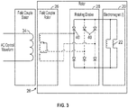
- FIG. 3 is a schematic diagram of aspects of an embodiment of the motor assembly 10.
- the electromagnet 20 is electrically connected to a series of rotating diodes 40 for each current phase, which convert the AC induced current into a DC current. This current is then used to energize the coils 22 of the electromagnet 20. As shown, the amount of current transferred from the field coupler 26 to the electromagnet 20 directly control the strength of the electromagnets affecting the total power of the motor assembly.
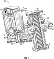
- FIG. 4 shows an example of an actuator assembly 50 that can incorporate the motor assembly 10.
- the actuator assembly 50 may be a linear actuator, a rotary actuator or any suitable type of actuator or other device that utilizes torque generated by the motor assembly 10.
- the electromagnet 20 can be energized to either strengthen or weaken the primary magnetic field generated by the stator windings 32 and the permanent magnet 14.
- the rotor shaft 16 is connected via a gear train 52 to a ball screw 54 that is turned by the motor assembly to generate linear motion.
- the ball screw 54 can be coupled to an actuator rod or other mechanism for moving an object or surface.
- the actuator assembly includes various other components, such as but not limited to, an internal anti-rotation post 56, load cell 58, a ball nut 60 and a seal tube 62.
- the rotor assembly 12 is incorporated into redundant motor topography, in which the rotor assembly 12 forms part of a primary motor that is used, e.g., to control an actuator.
- a secondary motor is operably connected to the primary motor, e.g., by a common rotor shaft or by respective rotor shafts joined with a differential. Sharing a common shaft can be useful for, e.g., weight reduction.
- the primary motor includes the permanent magnet 14, the electromagnet 20, the conversion device 28 and the field coupler 26.
- the secondary motor includes a secondary permanent magnet 70 and may also include a controllable magnetic device such as a secondary electromagnet 72, which can be operably connected to a secondary field coupler 74 via a conversion device 76.
- the primary and secondary motors may be controlled via a single controller 24, or by separate controllers. For example, the primary motor is controlled by the controller 24 and the secondary motor is independently controlled by a secondary controller 78.
- the secondary motor can be activated in the event of a failure of the primary motor or other condition for which the primary motor is insufficient for a given application.
- the permanent magnet 14 of the primary motor produces a back electromotive force (BEMF) which can impede movement of the secondary motor.
- BEMF back electromotive force
- the electromagnet 20 and/or the electromagnet 74 can be actuated and controlled to generate a magnetic field that reduces or eliminates the BEMF. In this way, in a dual redundant motor system, a failed motor can be effectively disengaged so that motors do not have to be sized up to drive through the BEMF.
- FIG. 5 illustrates a method 90 of manufacturing and/or operating an electric motor.
- the method 90 is discussed in conjunction with the motor assembly 10 and the rotor assembly 12, although the method 90 may be utilized in conjunction with any suitable device or system that can utilize an electric motor.
- the method 90 includes one or more stages 91-94. In one embodiment, the method 90 includes the execution of all of stages 91-94 in the order described. However, certain stages may be omitted, stages may be added, or the order of the stages changed.
- the motor assembly 10 is assembled and installed as part of, e.g., an actuator device, e.g., the actuator assembly 50.
- the actuator assembly 50 is installed as part of an aircraft control system and is controlled by a pilot, operator and/or processing device (e.g., aircraft computer).
- electric current is applied to the motor control stator windings 32, e.g., via three-phase current.
- the electric current flows circumferentially through the windings 32 around the permanent magnet 14, causing rotation of the permanent magnet 14 and the rotor shaft 16.
- a controllable magnet such as the electromagnet 20 is actuated and controlled as discussed above.
- the electromagnet 20 is energized by applying DC current via the field coupler 26 and the conversion device.
- the electromagnet 20 generates a magnetic field that interacts with the magnetic field in the rotor assembly 12 to either increase the magnetic flux density in the rotor assembly 12 or decrease the magnetic flux density.
- the torque generated by the assembly 10 may be transferred or translated to an actuator.
- the actuator may be a linear actuator and/or a rotary actuator used in an aircraft or in any other suitable environment.
- the torque is transferred to a component, e.g., an aileron or other moveable component of an aircraft.
- Other examples of the component include any moveable component or load (e.g., a pump).
- Embodiments described herein provide a number of advantages and technical effects.
- the motor assemblies described herein provide an electric motor assembly and/or an electric actuator that can change its performance curves to match the needs of a system more closely than conventional motors and actuators, and thus be more efficient relative to conventional motors and actuators, while being more fault tolerant of environment conditions and degraded components.
- the embodiments can produce a relatively high power density without having to increase the size of an electric motor or actuator and/or require stronger and more costly magnets.
- a conventional technique of redundancy reduction includes ganging lower reliability components together (such as a motor) to a single high reliability function (such as a linkage or pump). To do this, one must ensure that when a motor fails it does not inhibit other components. In the case of motors, this is accomplished through torque summing or disengagement clutches or release mechanisms, which adds weight cost and complexity back.
- a clutch or other mechanism is not needed.
- Embodiments described herein provide the ability to supplement a motor's native power without having to significantly increase the size or cost of the motor.
Description
- The subject matter disclosed herein relates to electric machines. More specifically, the subject disclosure relates to magnetic flux regulation of electric machines.
- Many electrical actuators employ a DC electric motor, such as a Permanent Magnet DC Motor (PMDCM) to move a surface or object. Typically, the size of the actuator is related to the available power that must be delivered. In some cases, electrical actuators are needed to be able to deliver maximum power under a wide range of conditions and faults, see for example
US2014/0285053 . - A PMDCM is limited in power by the available flux developed by the magnets on the rotor of the motor. In conventional PMDCMs, the magnetic field strength dictates the size of the rotor, because the rotor holds the permanent magnet(s). The higher the power, the more magnetic flux is needed, either through larger size or stronger magnets.
- According to one aspect of the invention an electric motor assembly that includes a primary electric motor including a primary rotor assembly and a primary stator assembly configured to be actuated to cause the primary rotor assembly to rotate based on an amount of magnetic flux in the rotor assembly is disclosed. The motor also includes: a secondary electric motor including a secondary rotor assembly and a secondary stator assembly; a controllable magnetic device coupled to at least one of the primary rotor assembly and the secondary rotor assembly; and a controller configured to actuate the secondary electric motor based on a failure of the primary electric motor, and apply electric current to the controllable magnetic device to reduce back electromotive force (BEMF) caused by rotation of the primary rotor assembly during actuation of the secondary electric motor.
- According to any aspect disclosed herein, the primary rotor assembly and the secondary rotor assembly are configured to rotate synchronously.
- According to any aspect disclosed herein, the controllable magnetic device includes a first controllable magnetic device coupled to the primary rotor assembly and a second controllable magnetic device coupled to the secondary.
- According to any aspect disclosed herein, the controllable magnetic device is configured to be actuated to weaken a magnetic field generated by a permanent magnet in the primary rotor assembly during actuation of the secondary electric motor.
- According to any aspect disclosed herein, the rotor assembly is connected to an actuator, and the controller is configured to increase an amount of torque generated by the secondary electric motor.
- According to any aspect disclosed herein, the controller includes a field coupler coupled to the controllable magnetic device, the field coupler configured to be energized by stationary windings.
- According to any aspect disclosed herein, the controller includes a rectifier device configured to convert alternating current generated by the field coupler to direct current and apply the direct current to the controllable magnetic device.
- According to any aspect disclosed herein, the controllable magnetic device includes one or more windings coupled to the rotatable member.
- According to any aspect disclosed herein, the primary rotor assembly includes a permanent magnet.
- According to any aspect disclosed herein, wherein the rotor assembly and the stator assembly form at least part of a brushless direct current (DC) motor.
- In one aspect, a method of controlling an electric motor assembly is disclosed. In this aspect the method includes: actuating a primary electric motor including a primary rotor assembly and a primary stator assembly, wherein actuating includes applying a first electric current to the primary stator assembly and causing the primary rotor assembly to rotate based on an amount of magnetic flux in the rotor assembly; based on a failure of the primary electric motor, actuating a secondary electric motor, the secondary electric motor including a secondary rotor assembly and a secondary stator assembly; and applying a second electric current by a controller to a controllable magnetic device coupled to at least one of the primary rotor assembly and the secondary rotor assembly, the second electric current causing the controllable magnetic device to reduce back electromotive force (BEMF) caused by rotation of the primary rotor assembly during actuation of the secondary electric motor.
- According to any aspect disclosed herein, the primary rotor assembly and the secondary rotor assembly are configured to rotate synchronously.
- According to any aspect disclosed herein, the controllable magnetic device includes a first controllable magnetic device coupled to the primary rotor assembly and a second controllable magnetic device coupled to the secondary.
- According to any aspect disclosed herein, the second electric current is applied to the controllable magnetic device to weaken a magnetic field generated by a permanent magnet in the primary rotor assembly during actuation of the secondary electric motor.
- According to any aspect disclosed herein, the rotor assembly is connected to an actuator, and the controller is configured to increase an amount of torque generated by the secondary electric motor.
- According to any aspect disclosed herein, the controller includes a field coupler coupled to the controllable magnetic device, the field coupler configured to be energized by stationary windings.
- According to any aspect disclosed herein, the controller includes a rectifier device configured to convert alternating current generated by the field coupler to direct current and apply the direct current to the controllable magnetic device.
- According to any aspect disclosed herein, the controllable magnetic device includes one or more windings coupled to the rotatable member.
- According to any aspect disclosed herein, the primary rotor assembly includes a permanent magnet.
- According to any aspect disclosed herein, the rotor assembly and the stator assembly form at least part of a brushless direct current (DC) motor.
- These and other advantages and features will become more apparent from the following description taken in conjunction with the drawings.
- The subject matter, which is regarded as the invention, is particularly pointed out and distinctly claimed in the claims at the conclusion of the specification. The foregoing and other features, and advantages of the invention are apparent from the following detailed description taken in conjunction with the accompanying drawings in which:
-
FIG. 1 depicts a rotor assembly of an embodiment of an electric motor assembly; -
FIG. 2 depicts the electric motor assembly ofFIG. 1 including the rotor assembly and a stator assembly; -
FIG. 3 depicts a rotor assembly of an embodiment of an electric motor assembly, which includes a field coupler connected to a controllable magnetic device by rotating diodes; and -
FIG. 4 depicts an embodiment of an actuator assembly including an electric motor assembly; -
FIG. 5 depicts an embodiment of an electric motor system having a primary electric motor and a redundant secondary electric motor; and -
FIG. 6 is a flow diagram depicting an embodiment of manufacturing and/or operating an electric motor assembly. - The detailed description explains embodiments of the invention, together with advantages and features, by way of example with reference to the drawings.
- Devices, systems and methods are provided herein for control of an electric motor. An embodiment of a motor assembly includes an electric motor (e.g., a permanent magnet DC motor) having a stator assembly and a rotor assembly. A controllable magnetic device is coupled to the rotor assembly and can be actuated and/or controlled to control an amount of magnetic flux in the rotor assembly. In one embodiment, the controllable magnetic device is an electromagnet formed by one or more windings that are mounted on a rotor shaft or otherwise coupled to the rotor assembly so that the windings rotate concurrently with the rotor assembly. The controllable magnetic device may be configured to increase the magnetic flux to, for example, increase the torque of the motor assembly and/or increase the power of an actuator coupled to the motor assembly. The controllable magnetic device can also be configured to decrease the magnetic flux.
- In one embodiment, the controllable magnet device is incorporated into a primary motor and/or a secondary (back-up or redundant) motor in a redundant motor topology. The secondary motor can be used to supplement the torque and power of the primary motor and/or be used in the event of a failure of the primary motor. The controllable magnetic device can be actuated to reduce the back electromotive force (BEMF) that can be generated by the failed primary motor when the secondary motor is in operation.
-
FIG. 1 illustrates aspects of an embodiment of an electric motor assembly, such as a permanent magnet DC (PMDC) motor assembly. Theelectric motor assembly 10 includes a stator assembly (not shown) and arotor assembly 12. Therotor assembly 12 includes a permanent magnet 14 (or a plurality of permanent magnets) mounted on arotor shaft 16 that extends longitudinally along amotor assembly axis 18. Thepermanent magnet 14 may be made of a rare-earth material or other suitable magnetic material. Therotor assembly 12 is configured to be disposed in a stator assembly (not shown), so that application of current to the stator assembly generates a current-induced magnetic field. Thepermanent magnet 14 couples with the current-induced magnetic field to cause rotation of thepermanent magnet 14 and therotor shaft 16. - The
motor assembly 10 also includes a controllable magnetic device that is configured to adjust the magnetic flux density in the rotor assembly 12 (i.e., in the gap between the stator and rotor assemblies). In one embodiment, the controllable magnetic device is anelectromagnet 20 formed bywindings 22 mounted on therotor assembly 12 so that thewindings 22 rotate with therotor assembly 12. Amotor control device 24 controls the magnetic field generated by theelectromagnet 20 via any suitable coupling device. Themotor control device 24 includes components for performing functions related to control of themotor assembly 10 and the controllable magnetic device, such as a processor, a memory, a power supply, an input/output device and others. - In one embodiment, the
motor assembly 10 includes afield coupler 26 connected to aconversion device 28. Thefield coupler 26 provides alternating current that is converted to a direct current. The direct current is then applied to theelectromagnet 22 to adjust the magnetic field flux density in therotor assembly 12. - The
motor control device 24 and theelectromagnet 20 provide a mechanism to vary the magnetic flux density in the air gap between the rotor and stator assemblies, thereby providing a variable flux motor assembly. By applying current in a first direction, theelectromagnet 20 can generate a magnetic field that increases the magnetic flux density and thereby increases motor power. By applying current in a reverse direction, theelectromagnet 20 can generate a magnet field that reduces the magnetic flux density (field weakening) and thereby reduces motor power. - By creating a controllable magnetic device or devices on the
rotor assembly 12, the available flux of a brushless permanent magnet DC motor or other motor (e.g., a brushed motor) can be increased to gain power in critical envelopes of operation. The size of themotor assembly 10 can also be reduced (e.g., the size of a typical rare earth magnet rotor can be reduced) as the peak power required can be accommodated by the use of additive flux provided by the controllable magnetic device or devices. -
FIG. 2 shows an example of themotor assembly 10, and illustrates an example of thefield coupler 26 and theconversion device 28. In this example, themotor assembly 10 includes a stator assembly that is mounted in astationary housing 30. Thehousing 30 may also house thepermanent magnet 14, theelectromagnet 20, thefield coupler 26 and/or theconversion device 28. The stator assembly includes motorcontrol stator windings 32 mounted in thehousing 30. - In one embodiment, the
field coupler 26 is configured to be inductively powered bystator windings 34, which may also be disposed in thehousing 30. Thefield coupler 26 includes a plurality of windings or coils configured to rotate with the rotor assembly. The field coupler coils may be mounted on therotor shaft 16, mounted on another shaft or member connected to therotor shaft 16 or in any manner so that the field coupler coils rotate with thepermanent magnet 14. - The
controller 24 may be a single controller or other processing device, or may including multiple controllers that operate different components of themotor assembly 10. In the example ofFIG. 2 , thecontroller 24 is configured to control both therotor assembly 12 and theelectromagnet 20, and is operably connected to thestator windings 32 and the fieldcoupler stator windings 34 by respective three-phase circuits - In the example of
FIG. 2 , theconversion device 28 includes a plurality of rotating diodes configured to rotate with therotor assembly 12. The rotating diodes act as a rectifier to convert AC current from the field coupler coils to DC current that is applied to theelectromagnet 20. -
FIG. 3 is a schematic diagram of aspects of an embodiment of themotor assembly 10. In this embodiment, theelectromagnet 20 is electrically connected to a series ofrotating diodes 40 for each current phase, which convert the AC induced current into a DC current. This current is then used to energize thecoils 22 of theelectromagnet 20. As shown, the amount of current transferred from thefield coupler 26 to theelectromagnet 20 directly control the strength of the electromagnets affecting the total power of the motor assembly. -
FIG. 4 shows an example of anactuator assembly 50 that can incorporate themotor assembly 10. Theactuator assembly 50 may be a linear actuator, a rotary actuator or any suitable type of actuator or other device that utilizes torque generated by themotor assembly 10. As discussed above, theelectromagnet 20 can be energized to either strengthen or weaken the primary magnetic field generated by thestator windings 32 and thepermanent magnet 14. - In this example, the
rotor shaft 16 is connected via agear train 52 to aball screw 54 that is turned by the motor assembly to generate linear motion. The ball screw 54 can be coupled to an actuator rod or other mechanism for moving an object or surface. The actuator assembly includes various other components, such as but not limited to, an internalanti-rotation post 56,load cell 58, aball nut 60 and aseal tube 62. - Referring to
FIG. 5 , in one embodiment, therotor assembly 12 is incorporated into redundant motor topography, in which therotor assembly 12 forms part of a primary motor that is used, e.g., to control an actuator. A secondary motor is operably connected to the primary motor, e.g., by a common rotor shaft or by respective rotor shafts joined with a differential. Sharing a common shaft can be useful for, e.g., weight reduction. - In this embodiment, the primary motor includes the
permanent magnet 14, theelectromagnet 20, theconversion device 28 and thefield coupler 26. The secondary motor includes a secondarypermanent magnet 70 and may also include a controllable magnetic device such as asecondary electromagnet 72, which can be operably connected to asecondary field coupler 74 via aconversion device 76. The primary and secondary motors may be controlled via asingle controller 24, or by separate controllers. For example, the primary motor is controlled by thecontroller 24 and the secondary motor is independently controlled by asecondary controller 78. - The secondary motor can be activated in the event of a failure of the primary motor or other condition for which the primary motor is insufficient for a given application. When the secondary motor is in use, the
permanent magnet 14 of the primary motor produces a back electromotive force (BEMF) which can impede movement of the secondary motor. To reduce or eliminate the BEMF, theelectromagnet 20 and/or theelectromagnet 74 can be actuated and controlled to generate a magnetic field that reduces or eliminates the BEMF. In this way, in a dual redundant motor system, a failed motor can be effectively disengaged so that motors do not have to be sized up to drive through the BEMF. -
FIG. 5 illustrates amethod 90 of manufacturing and/or operating an electric motor. Themethod 90 is discussed in conjunction with themotor assembly 10 and therotor assembly 12, although themethod 90 may be utilized in conjunction with any suitable device or system that can utilize an electric motor. Themethod 90 includes one or more stages 91-94. In one embodiment, themethod 90 includes the execution of all of stages 91-94 in the order described. However, certain stages may be omitted, stages may be added, or the order of the stages changed. - In the
first stage 91, themotor assembly 10 is assembled and installed as part of, e.g., an actuator device, e.g., theactuator assembly 50. For example, theactuator assembly 50 is installed as part of an aircraft control system and is controlled by a pilot, operator and/or processing device (e.g., aircraft computer). - In the
second stage 92, electric current is applied to the motorcontrol stator windings 32, e.g., via three-phase current. The electric current flows circumferentially through thewindings 32 around thepermanent magnet 14, causing rotation of thepermanent magnet 14 and therotor shaft 16. - In the
third stage 93, a controllable magnet such as theelectromagnet 20 is actuated and controlled as discussed above. For example, theelectromagnet 20 is energized by applying DC current via thefield coupler 26 and the conversion device. Theelectromagnet 20 generates a magnetic field that interacts with the magnetic field in therotor assembly 12 to either increase the magnetic flux density in therotor assembly 12 or decrease the magnetic flux density. - In the
fourth stage 94, the torque generated by theassembly 10 may be transferred or translated to an actuator. The actuator may be a linear actuator and/or a rotary actuator used in an aircraft or in any other suitable environment. For example, the torque is transferred to a component, e.g., an aileron or other moveable component of an aircraft. Other examples of the component include any moveable component or load (e.g., a pump). - Embodiments described herein provide a number of advantages and technical effects. The motor assemblies described herein provide an electric motor assembly and/or an electric actuator that can change its performance curves to match the needs of a system more closely than conventional motors and actuators, and thus be more efficient relative to conventional motors and actuators, while being more fault tolerant of environment conditions and degraded components. In addition, the embodiments can produce a relatively high power density without having to increase the size of an electric motor or actuator and/or require stronger and more costly magnets.
- Modern aircraft are becoming more electric in an effort to reduce weight and increase performance. Many aircraft systems in safety critical functions involve full redundancy to achieve required safety levels. There are several disadvantageous of such an architecture including high weight and cost. Embodiments described herein allow for the construction of motor assemblies that do not require full redundancy while satisfying desired safety criteria. For example, a conventional technique of redundancy reduction includes ganging lower reliability components together (such as a motor) to a single high reliability function (such as a linkage or pump). To do this, one must ensure that when a motor fails it does not inhibit other components. In the case of motors, this is accomplished through torque summing or disengagement clutches or release mechanisms, which adds weight cost and complexity back. By using a motor assembly with active field generation used to counteract permanent magnets as described herein, a clutch or other mechanism is not needed.
- As the use of electric motors becomes more prevalent in aircraft, the need for a variable power motor is also growing. Sizing a motor for peak loads that may be seen only during a small part (e.g., 5%) of the total operating time imposes a huge burden on the size and cost of the motor. Embodiments described herein provide the ability to supplement a motor's native power without having to significantly increase the size or cost of the motor.
Claims (15)
- An electric motor assembly (10) comprising:a primary electric motor including a primary rotor assembly (12) and a primary stator assembly configured to be actuated to cause the primary rotor assembly to rotate based on an amount of magnetic flux in the rotor assembly;a secondary electric motor including a secondary rotor assembly and a secondary stator assembly;a controllable magnetic device coupled to at least one of the primary rotor assembly and the secondary rotor assembly; characterised bya controller (24) configured to actuate the secondary electric motor based on a failure of the primary electric motor, and apply electric current to the controllable magnetic device to reduce back electromotive force (BEMF) caused by rotation of the primary rotor assembly during actuation of the secondary electric motor.
- The electric motor assembly of claim 1, wherein the primary rotor assembly and the secondary rotor assembly are configured to rotate synchronously.
- The electric motor assembly of claim 1 or 2, wherein the controllable magnetic device includes a first controllable magnetic device coupled to the primary rotor assembly and a second controllable magnetic device coupled to the secondary.
- The electric motor assembly of claim 1 or 2, wherein the controllable magnetic device is configured to be actuated to weaken a magnetic field generated by a permanent magnet (14) in the primary rotor assembly during actuation of the secondary electric motor.
- The electric motor assembly of any preceding claim, wherein the rotor assembly (12) is connected to an actuator, and the controller (24) is configured to increase an amount of torque generated by the secondary electric motor.
- The electric motor assembly of any preceding claim, wherein the controller (24) includes a field coupler coupled to the controllable magnetic device, the field coupler (26) configured to be energized by stationary windings.
- The electric motor assembly of claim 6, wherein the controller includes a rectifier device configured to convert alternating current generated by the field coupler to direct current and apply the direct current to the controllable magnetic device.
- The electric motor assembly of any preceding claim, wherein the controllable magnetic device includes one or more windings coupled to the rotatable member.
- The electric motor assembly of any preceding claim, wherein the primary rotor assembly includes a permanent magnet.
- The electric motor assembly of claim 9, wherein the rotor assembly and the stator assembly form at least part of a brushless direct current (DC) motor.
- A method (90) of controlling an electric motor assembly comprising:actuating a primary electric motor including a primary rotor assembly (12) and a primary stator assembly, wherein actuating includes applying (92) a first electric current to the primary stator assembly and causing the primary rotor assembly (12) to rotate based on an amount of magnetic flux in the rotor assembly;based on a failure of the primary electric motor, actuating a secondary electric motor, the secondary electric motor including a secondary rotor assembly and a secondary stator assembly; characterised byapplying (93) a second electric current by a controller to a controllable magnetic device coupled to at least one of the primary rotor assembly and the secondary rotor assembly, the second electric current causing the controllable magnetic device to reduce back electromotive force (BEMF) caused by rotation of the primary rotor assembly during actuation of the secondary electric motor.
- The method of claim 11, wherein the primary rotor assembly and the secondary rotor assembly are configured to rotate synchronously.
- The method of claim 11 or 12, wherein the controllable magnetic device includes a first controllable magnetic device coupled to the primary rotor assembly and a second controllable magnetic device coupled to the secondary.
- The method of claim 11, 12 or 13, wherein the second electric current is applied to the controllable magnetic device to weaken a magnetic field generated by a permanent magnet in the primary rotor assembly during actuation of the secondary electric motor.
- The method of any of claims 11 to 14, wherein the rotor assembly is connected to an actuator, and the controller is configured to increase an amount of torque generated by the secondary electric motor.
Applications Claiming Priority (1)
| Application Number | Priority Date | Filing Date | Title |
|---|---|---|---|
| US15/794,144 US10742078B2 (en) | 2017-10-26 | 2017-10-26 | Variable torque electric motor assembly |
Publications (2)
| Publication Number | Publication Date |
|---|---|
| EP3477845A1 EP3477845A1 (en) | 2019-05-01 |
| EP3477845B1 true EP3477845B1 (en) | 2020-06-10 |
Family
ID=63965343
Family Applications (1)
| Application Number | Title | Priority Date | Filing Date |
|---|---|---|---|
| EP18201963.8A Active EP3477845B1 (en) | 2017-10-26 | 2018-10-23 | Variable torque electric motor assembly |
Country Status (2)
| Country | Link |
|---|---|
| US (1) | US10742078B2 (en) |
| EP (1) | EP3477845B1 (en) |
Family Cites Families (8)
| Publication number | Priority date | Publication date | Assignee | Title |
|---|---|---|---|---|
| US4713570A (en) | 1986-06-04 | 1987-12-15 | Pacific Scientific Co. | Magnetically enhanced variable reluctance motor systems |
| US6472784B2 (en) * | 1997-12-16 | 2002-10-29 | Fred N. Miekka | Methods and apparatus for increasing power of permanent magnet motors |
| ES2158782B1 (en) | 1998-05-12 | 2002-03-01 | Mannesmann Sachs Ag | CONTROL SYSTEM AND PROCEDURE FOR A PERMANENTLY EXCITED ELECTRIC MOTOR WITH AT LEAST ONE PHASE. |
| JP3949916B2 (en) * | 2001-09-26 | 2007-07-25 | 日本電産サンキョー株式会社 | Magnetic levitation motor and magnetic bearing device |
| JP4400835B2 (en) | 2007-07-24 | 2010-01-20 | 本田技研工業株式会社 | Electric motor control device |
| CN101803176B (en) | 2007-09-18 | 2013-03-13 | 株式会社东芝 | Variable magnetic flux drive system |
| US8076882B2 (en) | 2007-12-26 | 2011-12-13 | Pratt & Whitney Canada Corp. | Motor drive architecture with active snubber |
| US9318937B2 (en) | 2013-03-20 | 2016-04-19 | Hamilton Sundstrand Corporation | Flux controlled PM electric machine rotor |
-
2017
- 2017-10-26 US US15/794,144 patent/US10742078B2/en active Active
-
2018
- 2018-10-23 EP EP18201963.8A patent/EP3477845B1/en active Active
Non-Patent Citations (1)
| Title |
|---|
| None * |
Also Published As
| Publication number | Publication date |
|---|---|
| US10742078B2 (en) | 2020-08-11 |
| EP3477845A1 (en) | 2019-05-01 |
| US20190131830A1 (en) | 2019-05-02 |
Similar Documents
| Publication | Publication Date | Title |
|---|---|---|
| US6541877B2 (en) | Wind power generation system | |
| EP2838186B1 (en) | Active-active redundant motor gear system | |
| US7064526B2 (en) | Fault tolerant architecture for permanent magnet starter generator subsystem | |
| CA2728235C (en) | Compact electromechanical actuator | |
| US9541142B2 (en) | Magnetorheological flight control clutch system | |
| US10378445B2 (en) | Gas turbine engine fuel system | |
| US11390378B2 (en) | Actuator in a landing gear system of an aircraft | |
| US10633987B2 (en) | Simplified pitch actuation system for a turbine engine propeller | |
| CN110701249B (en) | Parallel type dual-redundancy electric steering engine based on overrunning clutch | |
| CA2727467C (en) | Minimum temperature control for electromechanical actuator | |
| EP1865593A2 (en) | Electric motor brake engagement holdup system | |
| US10770994B2 (en) | Variable torque electric motor assembly | |
| EP3477845B1 (en) | Variable torque electric motor assembly | |
| US20140260249A1 (en) | Method and apparatus for improving electro-hydraulic and electro-mechanical integrated control systems of a steam turbine | |
| US10870481B2 (en) | Pitch actuation system for a turbomachine propeller | |
| EP3477832A1 (en) | Variable torque electric motor assembly | |
| Oyori et al. | A motor control design for the more electric aero engine fuel system | |
| Brando et al. | Electric steering for aircraft nose landing gears using axial-flux permanent-magnet motors | |
| Kumar et al. | A new fault tolerant dual rotor BLDC drive for electro-mechanical actuator in more electric aircraft applications | |
| Castellini et al. | Analysis and design of a linear electro-mechanical actuator for a high lift system | |
| Kulshreshtha et al. | Electric actuation for flight and engine control: evolution and challenges | |
| US11780569B2 (en) | Method for controlling an aircraft taxi system | |
| US20180170523A1 (en) | Electromechanical pitch actuation system for a turbomachine propeller | |
| US9771164B2 (en) | Electric system architecture included in a more-electric engine (MEE) system | |
| D’Andrea et al. | Electromagnetic design of a fault tolerant electromechanical actuator for landing gear |
Legal Events
| Date | Code | Title | Description |
|---|---|---|---|
| PUAI | Public reference made under article 153(3) epc to a published international application that has entered the european phase |
Free format text: ORIGINAL CODE: 0009012 |
|
| STAA | Information on the status of an ep patent application or granted ep patent |
Free format text: STATUS: THE APPLICATION HAS BEEN PUBLISHED |
|
| AK | Designated contracting states |
Kind code of ref document: A1 Designated state(s): AL AT BE BG CH CY CZ DE DK EE ES FI FR GB GR HR HU IE IS IT LI LT LU LV MC MK MT NL NO PL PT RO RS SE SI SK SM TR |
|
| AX | Request for extension of the european patent |
Extension state: BA ME |
|
| STAA | Information on the status of an ep patent application or granted ep patent |
Free format text: STATUS: REQUEST FOR EXAMINATION WAS MADE |
|
| 17P | Request for examination filed |
Effective date: 20191029 |
|
| RBV | Designated contracting states (corrected) |
Designated state(s): AL AT BE BG CH CY CZ DE DK EE ES FI FR GB GR HR HU IE IS IT LI LT LU LV MC MK MT NL NO PL PT RO RS SE SI SK SM TR |
|
| GRAP | Despatch of communication of intention to grant a patent |
Free format text: ORIGINAL CODE: EPIDOSNIGR1 |
|
| STAA | Information on the status of an ep patent application or granted ep patent |
Free format text: STATUS: GRANT OF PATENT IS INTENDED |
|
| INTG | Intention to grant announced |
Effective date: 20200103 |
|
| GRAS | Grant fee paid |
Free format text: ORIGINAL CODE: EPIDOSNIGR3 |
|
| GRAA | (expected) grant |
Free format text: ORIGINAL CODE: 0009210 |
|
| STAA | Information on the status of an ep patent application or granted ep patent |
Free format text: STATUS: THE PATENT HAS BEEN GRANTED |
|
| AK | Designated contracting states |
Kind code of ref document: B1 Designated state(s): AL AT BE BG CH CY CZ DE DK EE ES FI FR GB GR HR HU IE IS IT LI LT LU LV MC MK MT NL NO PL PT RO RS SE SI SK SM TR |
|
| REG | Reference to a national code |
Ref country code: GB Ref legal event code: FG4D |
|
| REG | Reference to a national code |
Ref country code: CH Ref legal event code: EP Ref country code: AT Ref legal event code: REF Ref document number: 1279973 Country of ref document: AT Kind code of ref document: T Effective date: 20200615 |
|
| REG | Reference to a national code |
Ref country code: DE Ref legal event code: R096 Ref document number: 602018005196 Country of ref document: DE |
|
| REG | Reference to a national code |
Ref country code: IE Ref legal event code: FG4D |
|
| REG | Reference to a national code |
Ref country code: LT Ref legal event code: MG4D |
|
| PG25 | Lapsed in a contracting state [announced via postgrant information from national office to epo] |
Ref country code: NO Free format text: LAPSE BECAUSE OF FAILURE TO SUBMIT A TRANSLATION OF THE DESCRIPTION OR TO PAY THE FEE WITHIN THE PRESCRIBED TIME-LIMIT Effective date: 20200910 Ref country code: SE Free format text: LAPSE BECAUSE OF FAILURE TO SUBMIT A TRANSLATION OF THE DESCRIPTION OR TO PAY THE FEE WITHIN THE PRESCRIBED TIME-LIMIT Effective date: 20200610 Ref country code: GR Free format text: LAPSE BECAUSE OF FAILURE TO SUBMIT A TRANSLATION OF THE DESCRIPTION OR TO PAY THE FEE WITHIN THE PRESCRIBED TIME-LIMIT Effective date: 20200911 Ref country code: FI Free format text: LAPSE BECAUSE OF FAILURE TO SUBMIT A TRANSLATION OF THE DESCRIPTION OR TO PAY THE FEE WITHIN THE PRESCRIBED TIME-LIMIT Effective date: 20200610 Ref country code: LT Free format text: LAPSE BECAUSE OF FAILURE TO SUBMIT A TRANSLATION OF THE DESCRIPTION OR TO PAY THE FEE WITHIN THE PRESCRIBED TIME-LIMIT Effective date: 20200610 |
|
| REG | Reference to a national code |
Ref country code: NL Ref legal event code: MP Effective date: 20200610 |
|
| PG25 | Lapsed in a contracting state [announced via postgrant information from national office to epo] |
Ref country code: BG Free format text: LAPSE BECAUSE OF FAILURE TO SUBMIT A TRANSLATION OF THE DESCRIPTION OR TO PAY THE FEE WITHIN THE PRESCRIBED TIME-LIMIT Effective date: 20200910 Ref country code: LV Free format text: LAPSE BECAUSE OF FAILURE TO SUBMIT A TRANSLATION OF THE DESCRIPTION OR TO PAY THE FEE WITHIN THE PRESCRIBED TIME-LIMIT Effective date: 20200610 Ref country code: RS Free format text: LAPSE BECAUSE OF FAILURE TO SUBMIT A TRANSLATION OF THE DESCRIPTION OR TO PAY THE FEE WITHIN THE PRESCRIBED TIME-LIMIT Effective date: 20200610 Ref country code: HR Free format text: LAPSE BECAUSE OF FAILURE TO SUBMIT A TRANSLATION OF THE DESCRIPTION OR TO PAY THE FEE WITHIN THE PRESCRIBED TIME-LIMIT Effective date: 20200610 |
|
| REG | Reference to a national code |
Ref country code: AT Ref legal event code: MK05 Ref document number: 1279973 Country of ref document: AT Kind code of ref document: T Effective date: 20200610 |
|
| PG25 | Lapsed in a contracting state [announced via postgrant information from national office to epo] |
Ref country code: AL Free format text: LAPSE BECAUSE OF FAILURE TO SUBMIT A TRANSLATION OF THE DESCRIPTION OR TO PAY THE FEE WITHIN THE PRESCRIBED TIME-LIMIT Effective date: 20200610 Ref country code: NL Free format text: LAPSE BECAUSE OF FAILURE TO SUBMIT A TRANSLATION OF THE DESCRIPTION OR TO PAY THE FEE WITHIN THE PRESCRIBED TIME-LIMIT Effective date: 20200610 |
|
| PG25 | Lapsed in a contracting state [announced via postgrant information from national office to epo] |
Ref country code: EE Free format text: LAPSE BECAUSE OF FAILURE TO SUBMIT A TRANSLATION OF THE DESCRIPTION OR TO PAY THE FEE WITHIN THE PRESCRIBED TIME-LIMIT Effective date: 20200610 Ref country code: SM Free format text: LAPSE BECAUSE OF FAILURE TO SUBMIT A TRANSLATION OF THE DESCRIPTION OR TO PAY THE FEE WITHIN THE PRESCRIBED TIME-LIMIT Effective date: 20200610 Ref country code: IT Free format text: LAPSE BECAUSE OF FAILURE TO SUBMIT A TRANSLATION OF THE DESCRIPTION OR TO PAY THE FEE WITHIN THE PRESCRIBED TIME-LIMIT Effective date: 20200610 Ref country code: ES Free format text: LAPSE BECAUSE OF FAILURE TO SUBMIT A TRANSLATION OF THE DESCRIPTION OR TO PAY THE FEE WITHIN THE PRESCRIBED TIME-LIMIT Effective date: 20200610 Ref country code: PT Free format text: LAPSE BECAUSE OF FAILURE TO SUBMIT A TRANSLATION OF THE DESCRIPTION OR TO PAY THE FEE WITHIN THE PRESCRIBED TIME-LIMIT Effective date: 20201012 Ref country code: AT Free format text: LAPSE BECAUSE OF FAILURE TO SUBMIT A TRANSLATION OF THE DESCRIPTION OR TO PAY THE FEE WITHIN THE PRESCRIBED TIME-LIMIT Effective date: 20200610 Ref country code: RO Free format text: LAPSE BECAUSE OF FAILURE TO SUBMIT A TRANSLATION OF THE DESCRIPTION OR TO PAY THE FEE WITHIN THE PRESCRIBED TIME-LIMIT Effective date: 20200610 Ref country code: CZ Free format text: LAPSE BECAUSE OF FAILURE TO SUBMIT A TRANSLATION OF THE DESCRIPTION OR TO PAY THE FEE WITHIN THE PRESCRIBED TIME-LIMIT Effective date: 20200610 |
|
| PG25 | Lapsed in a contracting state [announced via postgrant information from national office to epo] |
Ref country code: PL Free format text: LAPSE BECAUSE OF FAILURE TO SUBMIT A TRANSLATION OF THE DESCRIPTION OR TO PAY THE FEE WITHIN THE PRESCRIBED TIME-LIMIT Effective date: 20200610 Ref country code: SK Free format text: LAPSE BECAUSE OF FAILURE TO SUBMIT A TRANSLATION OF THE DESCRIPTION OR TO PAY THE FEE WITHIN THE PRESCRIBED TIME-LIMIT Effective date: 20200610 Ref country code: IS Free format text: LAPSE BECAUSE OF FAILURE TO SUBMIT A TRANSLATION OF THE DESCRIPTION OR TO PAY THE FEE WITHIN THE PRESCRIBED TIME-LIMIT Effective date: 20201010 |
|
| REG | Reference to a national code |
Ref country code: DE Ref legal event code: R097 Ref document number: 602018005196 Country of ref document: DE |
|
| PLBE | No opposition filed within time limit |
Free format text: ORIGINAL CODE: 0009261 |
|
| STAA | Information on the status of an ep patent application or granted ep patent |
Free format text: STATUS: NO OPPOSITION FILED WITHIN TIME LIMIT |
|
| PG25 | Lapsed in a contracting state [announced via postgrant information from national office to epo] |
Ref country code: DK Free format text: LAPSE BECAUSE OF FAILURE TO SUBMIT A TRANSLATION OF THE DESCRIPTION OR TO PAY THE FEE WITHIN THE PRESCRIBED TIME-LIMIT Effective date: 20200610 |
|
| 26N | No opposition filed |
Effective date: 20210311 |
|
| PG25 | Lapsed in a contracting state [announced via postgrant information from national office to epo] |
Ref country code: SI Free format text: LAPSE BECAUSE OF FAILURE TO SUBMIT A TRANSLATION OF THE DESCRIPTION OR TO PAY THE FEE WITHIN THE PRESCRIBED TIME-LIMIT Effective date: 20200610 |
|
| PG25 | Lapsed in a contracting state [announced via postgrant information from national office to epo] |
Ref country code: LU Free format text: LAPSE BECAUSE OF NON-PAYMENT OF DUE FEES Effective date: 20201023 Ref country code: MC Free format text: LAPSE BECAUSE OF FAILURE TO SUBMIT A TRANSLATION OF THE DESCRIPTION OR TO PAY THE FEE WITHIN THE PRESCRIBED TIME-LIMIT Effective date: 20200610 |
|
| REG | Reference to a national code |
Ref country code: BE Ref legal event code: MM Effective date: 20201031 |
|
| PG25 | Lapsed in a contracting state [announced via postgrant information from national office to epo] |
Ref country code: BE Free format text: LAPSE BECAUSE OF NON-PAYMENT OF DUE FEES Effective date: 20201031 |
|
| PG25 | Lapsed in a contracting state [announced via postgrant information from national office to epo] |
Ref country code: IE Free format text: LAPSE BECAUSE OF NON-PAYMENT OF DUE FEES Effective date: 20201023 |
|
| REG | Reference to a national code |
Ref country code: CH Ref legal event code: PL |
|
| PG25 | Lapsed in a contracting state [announced via postgrant information from national office to epo] |
Ref country code: TR Free format text: LAPSE BECAUSE OF FAILURE TO SUBMIT A TRANSLATION OF THE DESCRIPTION OR TO PAY THE FEE WITHIN THE PRESCRIBED TIME-LIMIT Effective date: 20200610 Ref country code: MT Free format text: LAPSE BECAUSE OF FAILURE TO SUBMIT A TRANSLATION OF THE DESCRIPTION OR TO PAY THE FEE WITHIN THE PRESCRIBED TIME-LIMIT Effective date: 20200610 Ref country code: CY Free format text: LAPSE BECAUSE OF FAILURE TO SUBMIT A TRANSLATION OF THE DESCRIPTION OR TO PAY THE FEE WITHIN THE PRESCRIBED TIME-LIMIT Effective date: 20200610 |
|
| PG25 | Lapsed in a contracting state [announced via postgrant information from national office to epo] |
Ref country code: MK Free format text: LAPSE BECAUSE OF FAILURE TO SUBMIT A TRANSLATION OF THE DESCRIPTION OR TO PAY THE FEE WITHIN THE PRESCRIBED TIME-LIMIT Effective date: 20200610 |
|
| PG25 | Lapsed in a contracting state [announced via postgrant information from national office to epo] |
Ref country code: LI Free format text: LAPSE BECAUSE OF NON-PAYMENT OF DUE FEES Effective date: 20211031 Ref country code: CH Free format text: LAPSE BECAUSE OF NON-PAYMENT OF DUE FEES Effective date: 20211031 |
|
| P01 | Opt-out of the competence of the unified patent court (upc) registered |
Effective date: 20230522 |
|
| PGFP | Annual fee paid to national office [announced via postgrant information from national office to epo] |
Ref country code: GB Payment date: 20230920 Year of fee payment: 6 |
|
| PGFP | Annual fee paid to national office [announced via postgrant information from national office to epo] |
Ref country code: FR Payment date: 20230920 Year of fee payment: 6 |
|
| PGFP | Annual fee paid to national office [announced via postgrant information from national office to epo] |
Ref country code: DE Payment date: 20230920 Year of fee payment: 6 |