EP3477800A1 - Spark plug production method - Google Patents
Spark plug production method Download PDFInfo
- Publication number
- EP3477800A1 EP3477800A1 EP17815012.4A EP17815012A EP3477800A1 EP 3477800 A1 EP3477800 A1 EP 3477800A1 EP 17815012 A EP17815012 A EP 17815012A EP 3477800 A1 EP3477800 A1 EP 3477800A1
- Authority
- EP
- European Patent Office
- Prior art keywords
- electrode
- base material
- tip
- electrode base
- contact
- Prior art date
- Legal status (The legal status is an assumption and is not a legal conclusion. Google has not performed a legal analysis and makes no representation as to the accuracy of the status listed.)
- Granted
Links
Images



Classifications
-
- H—ELECTRICITY
- H01—ELECTRIC ELEMENTS
- H01T—SPARK GAPS; OVERVOLTAGE ARRESTERS USING SPARK GAPS; SPARKING PLUGS; CORONA DEVICES; GENERATING IONS TO BE INTRODUCED INTO NON-ENCLOSED GASES
- H01T21/00—Apparatus or processes specially adapted for the manufacture or maintenance of spark gaps or sparking plugs
- H01T21/02—Apparatus or processes specially adapted for the manufacture or maintenance of spark gaps or sparking plugs of sparking plugs
-
- H—ELECTRICITY
- H01—ELECTRIC ELEMENTS
- H01T—SPARK GAPS; OVERVOLTAGE ARRESTERS USING SPARK GAPS; SPARKING PLUGS; CORONA DEVICES; GENERATING IONS TO BE INTRODUCED INTO NON-ENCLOSED GASES
- H01T13/00—Sparking plugs
- H01T13/20—Sparking plugs characterised by features of the electrodes or insulation
- H01T13/32—Sparking plugs characterised by features of the electrodes or insulation characterised by features of the earthed electrode
Definitions
- the present invention relates to a method for manufacturing a spark plug and particularly relates to a method for manufacturing a spark plug such that variations in welding of an electrode base material and a tip can be suppressed.
- a spark plug which includes: a ground electrode in which a tip containing a noble metal is joined to an electrode base material; and a center electrode opposing the ground electrode with a spark gap therebetween.
- Resistance welding is one of the methods for joining the electrode base material and the tip together. Resistance welding is performed by applying current between the first electrode and the second electrode, in a state where the electrode base material and the tip stacked with each other are in contact with a first electrode and a second electrode, respectively.
- Patent Document 1 discloses a technique in which the surface of the electrode base material is ground and then resistance welding is performed in a state where the tip is stacked on the ground surface.
- Patent Document 1 Japanese Patent Application Laid-Open (kokai) No. 2004-186152
- the above-described conventional technique has the following problem.
- resistance welding the electrode base material and the tip are melted and bonded to each other by Joule heat generated by contact resistance between the electrode base material and the tip.
- variations occur in contact resistance between the electrode base material and the first electrode and contact resistance between the tip and the second electrode, variations occur in welding of the tip and the electrode base material.
- the present invention has been made in order to solve the aforementioned problem, and an object of the present invention is to provide a method for manufacturing a spark plug such that variations in welding of an electrode base material and a tip can be suppressed.
- a tip containing a noble metal is joined to an electrode base material by means of resistance welding in which current is applied between a first electrode and a second electrode, so that a ground electrode is obtained.
- a first step a first surface having an area larger than or equal to an area making contact with the tip is produced on the electrode base material by performing at least one of polishing and grinding thereon.
- a second step a second surface having an area larger than or equal to an area making contact with the first electrode is produced on the electrode base material by performing at least one of polishing and grinding thereon.
- resistance welding is performed by applying current between the first electrode and the second electrode, after the first surface of the electrode base material and the tip have been brought into contact with each other, the first electrode has been brought into contact with the second surface of the electrode base material, and the second electrode has been brought into contact with the tip. Since variations in contact resistance between the electrode base material and the first electrode and variations in contact resistance between the tip and the second electrode can be suppressed, an effect of suppressing variations in welding of the electrode base material and the tip can be obtained.
- An arithmetic average roughness of the first surface is not less than an arithmetic average roughness of the second surface. Since the Joule heat that melts the tip and the electrode base material during welding depends on the contact resistance between the first surface of the electrode base material and the tip, in a case where the arithmetic average roughness of the first surface is set to be not less than the arithmetic average roughness of the second surface, the contact resistance between the first surface of the electrode base material and the tip can be ensured. Since the Joule heat generated between the tip and the electrode base material can be ensured, an effect of ensuring joining strength between the electrode base material and the tip can be obtained.
- the arithmetic average roughness of each of the first surface and the second surface of the electrode base material is 2 to 4 ⁇ m
- the arithmetic average roughness of each of a third surface and a fourth surface of the tip is 0.4 to 0.8 ⁇ m.
- the method for manufacturing the spark plug according to a third aspect of the present invention includes an assembling step of assembling a tubular insulator and a tubular metal shell to which the ground electrode is joined, wherein after the assembling step, an electrode base material adjusting step is performed.
- an effect of further improving the joining strength between the electrode base material and the tip can be obtained.
- the method for manufacturing the spark plug according to a fourth aspect of the present invention includes a third step of producing the third surface on the tip by performing at least one of polishing and grinding thereon, and a fourth step of producing the fourth surface on the tip by performing at least one of polishing and grinding thereon. As a result, the arithmetic average roughness of each of the third surface and the fourth surface of the tip can be easily adjusted.
- FIG. 1 is a cross-sectional view of a spark plug 10, according to an embodiment of the present invention, taken along a plane including a central axis O thereof.
- the spark plug 10 includes a metal shell 11, a ground electrode 12, an insulator 15, a center electrode 17, and a metal terminal 18.
- the metal shell 11 is a substantially cylindrical member that is fixed in a thread hole of an internal combustion engine (not shown).
- the ground electrode 12 includes: an electrode base material 13 that is made of metal (e.g., a nickel-based alloy) and that is joined to a front end of the metal shell 11; and a tip 14 that is joined to the front end of the electrode base material 13.
- the electrode base material 13 is a rod-shaped member that is bent toward the central axis O so as to intersect the central axis O.
- the tip 14 is a plate-shaped member formed of a noble metal such as platinum, iridium, ruthenium, or rhodium, or an alloy containing such a noble metal as a principal component, and is joined to the electrode base material 13 by means of resistance welding.
- the insulator 15 is a substantially cylindrical member formed of alumina or the like that has excellent mechanical property and insulation property at a high temperature, has an axial hole 16 that penetrates therethrough along the central axis O, and has an outer circumference on which the metal shell 11 is fixed.
- the center electrode 17 is a rod-shaped electrode that is inserted into the axial hole 16 and held by the insulator 15, and opposes the tip 14 of the ground electrode 12 with a spark gap therebetween.
- the metal terminal 18 is a rod-shaped member to which a high-voltage cable (not shown) is connected, and a front side of the metal terminal 18 is disposed in the insulator 15.
- the spark plug 10 is manufactured by, for example, a method described below. Firstly, the center electrode 17 is inserted into the axial hole 16 of the insulator 15. The center electrode 17 is disposed such that the front end thereof is exposed to the outside from the front end of the axial hole 16. After the metal terminal 18 is inserted into the axial hole 16, so that electrical connection is ensured between the metal terminal 18 and the center electrode 17, the metal shell 11 to which the ground electrode 12 has been joined in advance is assembled to the outer circumference of the insulator 15. After the tip 14 has been joined to the electrode base material 13 of the ground electrode 12 by means of resistance welding, the electrode base material 13 is bent such that the tip 14 opposes the center electrode 17 in the axial direction, so that the spark plug 10 is obtained.
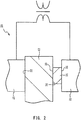
- FIG. 2 is a schematic view of a resistance welding machine 20 used in a welding step.
- a portion of the electrode base material 13 in a longitudinal direction is not shown.
- the resistance welding machine 20 includes a first electrode 21 and a second electrode 22 to both of which a transformer is connected. Welding of the electrode base material 13 and the tip 14 is performed by means of resistance welding in which current is applied between the first electrode 21 and the second electrode 22, after the electrode base material 13 and the tip 14 have been brought into contact with each other, the first electrode 21 has been brought into contact with the electrode base material 13, and the second electrode 22 has been brought into contact with the tip 14.
- a first surface 31 of the electrode base material 13 makes contact with a third surface 33 of the tip 14.
- a contact surface 21a of the first electrode 21 is brought into contact with a second surface 32 of the electrode base material 13, and a contact surface 22a of the second electrode 22 is brought into contact with a fourth surface 34 of the tip 14.
- FIG. 3 is a perspective view of the tip 14 and the electrode base material 13. In FIG. 3 , a portion of the electrode base material 13 in the longitudinal direction is not shown. FIG. 3 shows a state before resistance welding is performed.
- the electrode base material 13 has the second surface 32 and the first surface 31 that is different from the second surface 32.
- the second surface 32 is a surface having an area larger than or equal to an area 35 making contact with the contact surface 21a of the first electrode 21, and is produced by performing at least one of polishing and grinding on the electrode base material 13.
- the first surface 31 is a surface having an area larger than or equal to an area making contact with the third surface 33 of the tip 14, and is produced by performing at least one of polishing and grinding on the electrode base material 13.
- the first surface 31 is provided on a surface reverse to the second surface 32.
- the tip 14 has the fourth surface 34 on the back of the third surface 33.
- the third surface 33 is a surface having an area larger than or equal to an area making contact with the first surface 31 of the electrode base material 13
- the fourth surface 34 is a surface having an area larger than or equal to an area making contact with the contact surface 22a of the second electrode 22. It is noted that the third surface 33 and the fourth surface 34 may be formed by punching out a plate material having a predetermined surface roughness in a predetermined size, or may be formed by performing at least one of polishing and grinding on the tip 14.
- the second surface 32 of the electrode base material 13 is produced in such a size that the contact surface 21a of the first electrode 21 does not make contact with a surface 36 (the surface on which grinding or polishing is not performed) other than the second surface 32.
- a surface 36 the surface on which grinding or polishing is not performed
- the entirety of the second surface 32 can be easily brought into contact with the contact surface 21a of the first electrode 21.
- the diameter of the contact surface 21a of the first electrode 21 is greater than the width of the electrode base material 13, when an electrode surface 21a makes contact with the electrode base material 13, the contact surface 21a protrudes in a width direction of the electrode base material 13.
- the area of the first surface 31 of the electrode base material 13 is made larger than the area of the third surface 33 of the tip 14. Therefore, the entirety of the third surface 33 of the tip 14 can be easily brought into contact with the first surface 31.
- the area of the contact surface 22a of the second electrode 22 is made larger than the area of the fourth surface 34 of the tip 14. Therefore, the entirety of the fourth surface 34 of the tip 14 can be easily brought into contact with the contact surface 22a of the second electrode 22.
- the first surface 31 and the second surface 32 are each produced by a mechanical means using a grinding stone, a polishing material, a polishing cloth, abrasive paper, a polishing disc, a polishing belt, a polishing sleeve, a polishing wheel, a polishing brush, or the like. Grinding is an operation of chipping away at the surface and physically scraping the surface, and polishing is an operation of polishing the surface and decreasing surface roughness. Both polishing and grinding can be performed on the electrode base material 13, and only any one of grinding and polishing can also be performed on the electrode base material 13.
- polishing is suitably performed. This is because, since the amount to be chipped away from the surface by polishing can be further reduced as compared with that by grinding, surface roughness can be small while preventing decrease in accuracy of the dimensions of the electrode base material 13, and oxide film, oil film, and the like that attach to the surface can further be removed. It is noted that dry type grinding or dry type polishing that allows dispensing with an operation of drying or removing attachment after grinding or polishing is suitably used.
- the arithmetic average roughness of the first surface 31 is set to be not less than the arithmetic average roughness of the second surface 32. That is, Joule heat generated in the tip 14 and the electrode base material 13 depends on the contact resistance between the first surface 31 of the electrode base material 13 and the third surface 33 of the tip 14.
- the contact resistance between the tip 14 and the electrode base material 13 can be greater than the contact resistance between the first electrode 21 and the electrode base material 13. Since the contact resistance between the first surface 31 of the electrode base material 13 and the tip 14 can be ensured, Joule heat generated between the tip 14 and the electrode base material 13 can be ensured. As a result, joining strength between the electrode base material 13 and the tip 14 can be ensured.
- An arithmetic average roughness Ra is measured on the basis of JIS B0601 (1994 Edition).
- the arithmetic average roughness Ra is measured by means of VK-X110/X100 (manufactured by KEYENCE CORPORATION), which is a non-contact type shape measuring laser microscope.
- the arithmetic average roughness of each of the first surface 31 and the second surface 32 of the electrode base material 13 is 2 to 4 ⁇ m.
- the arithmetic average roughness of each of the third surface 33 and the fourth surface 34 of the tip 14 is 0.4 to 0.8 ⁇ m.
- the arithmetic average roughness of each of the third surface 33 and the fourth surface 34 of the tip 14 is 0.4 to 0.8 ⁇ m, in a case where the arithmetic average roughness of each of the first surface 31 and the second surface 32 of the electrode base material 13 is greater than 4 ⁇ m or less than 2 ⁇ m, the joining strength between the electrode base material 13 and the tip 14 tends to decrease.
- each electrode base material is formed from a nickel-based alloy, and each tip is formed from a platinum-nickel alloy. Dry type polishing was performed on a front surface and a rear surface of each electrode base material by means of a polishing belt, so that a rectangular-shaped first surface and a rectangular-shaped second surface each having a length of 6 mm and a width of 2.7 mm were produced on the front surface and the rear surface, respectively, of the electrode base material. Similarly, dry type polishing was performed on a front surface and a rear surface of each tip, so that a third surface and a fourth surface were produced on the front surface and the rear surface, respectively, of the tip.
- the arithmetic average roughness Ra of each of the first surface and the second surface of each of the 30 electrode base materials and the arithmetic average roughness Ra of each of the third surface and the fourth surface of each of the 30 tips were measured in a non-contact manner by means of VK-X110/X100 (manufactured by KEYENCE CORPORATION), which is the shape measuring laser microscope.
- the arithmetic average roughness of each of the first surface and the second surface of the electrode base material was obtained by measuring a rectangular range of 2.7 mm ⁇ 1 mm of the first surface or the second surface.
- the arithmetic average roughness of each of the first surface and the second surface was in the range of 2.8 to 3.5 ⁇ m, and the arithmetic average roughness of each of the third surface and the fourth surface was in the range of 0.45 to 0.8 ⁇ m.
- the tip was placed on the second electrode such that the fourth surface made contact with the second electrode of a resistance welding machine (power supply system was a single-phase AC system), the third surface of the tip and the first surface of the electrode base material were stacked with each other, and the first electrode was pressed onto the second surface of the electrode base material.
- Resistance welding was performed by pressing the first electrode and the second electrode to apply a load of 330N in the thickness direction of the tip and the electrode base material, and by applying current between the first electrode and the second electrode (the number of current application cycles was 7, and the number of slopes that are a rise of the applied current was 2).
- the first electrode and the second electrode each were a cylindrical electrode having a diameter of 5 mm.
- the first electrode succeeded in not making contact with the surface other than the second surface.
- the output of power supply of the resistance welding machine was made constant, each of the 30 tips and each of the 30 electrode base materials were mutually welded, and a standard deviation of effective values (A) of current during 30 times of welding was measured.
- a standard deviation of effective values (A) of current during 30 times of welding was measured as similar to Example 1, except that dry type polishing was performed on the front surface and the rear surface of each electrode base material by means of the polishing belt, so that a rectangular-shaped first surface and a rectangular-shaped second surface each having a length of 3 mm and a width of 2.7 mm were produced on the front surface and the rear surface, respectively, of the electrode base material.
- Comparative Example 1 is different from Example 1 in that the length of the second surface was shorter than the diameter of the first electrode.
- the first electrode had a diameter of 5 mm and the second surface, produced on the electrode base material, had a size of 3 mm ⁇ 2.7 mm, in Comparative Example 1, the first electrode made contact also with the unpolished surface other than the second surface. The entirety of the third surface of the tip made contact with the first surface produced on the electrode base material.
- a standard deviation of effective values (A) of current during 30 times of welding was measured as similar to Example 1, except that dry type polishing was performed on each electrode base material by means of the polishing belt so that a rectangular-shaped second surface having a length of 3 mm and a width of 2.7 mm was produced on the electrode base material.
- Comparative Example 2 is different from Example 1 in that the length of the second surface was shorter than the diameter of the first electrode and that the first surface was not produced on the electrode base material.
- the first electrode had a diameter of 5 mm and the second surface, produced on the electrode base material, had a size of 3 mm ⁇ 2.7 mm, in Comparative Example 2, the first electrode made contact also with the unpolished surface other than the second surface. In addition, since the first surface was not produced on the electrode base material, the tip made contact with the unpolished surface of the electrode base material.
- a standard deviation of effective values (A) of current during 30 times of welding was measured as similar to Example 1, except that polishing was not performed on each electrode base material.
- Comparative Example 3 is different from Example 1 in that the first surface and the second surface were not produced on the electrode base material.
- the arithmetic average roughness was measured for the front surface and the rear surface of the electrode base material on which polishing was not performed, the arithmetic surface roughness was 2.5 to 3.0 ⁇ m. Since, in Comparative Example 3, the first surface and the second surface were not produced on the electrode base material, the tip and the first electrode made contact with the respective unpolished surfaces of the electrode base material.
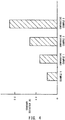
- FIG. 4 shows the measurement results of a standard deviation of effective values (A). It was found that, as shown in FIG. 4 , the standard deviation became smaller in descending order of Comparative Example 3, Comparative Example 2, and Comparative Example 1, and that Example 1 was able to have the smallest standard deviation of the four.
- Comparative Example 1 is different from Example 1 in that the first electrode makes contact also with the unpolished surface other than the second surface. It is assumed that, when the first electrode makes contact with the unpolished surface other than the second surface, variations in contact resistance between the first electrode and the electrode base material become greater because of foreign matter, such as oil film or impurities, which attach to the unpolished surface. Accordingly, it is assumed that variations in effective values during welding became greater. In Example 1, variations in welding of the electrode base material and the tip can be suppressed, since the smaller the standard deviation of effective values during welding is, the less the individual difference among ground electrodes obtained by welding is.
- rectangular-shaped electrode base materials each formed from a nickel-based alloy
- disc-shaped tips each having a diameter of 1 mm and a thickness of 0.4 mm
- Dry type polishing was performed on the front surface and the rear surface of each electrode base material by means of the polishing disc, so that a rectangular-shaped first surface and a rectangular-shaped second surface each having a length of 6 mm and a width of 2.7 mm were produced on the front surface and the rear surface, respectively, of the electrode base material.
- dry type polishing was performed on the front surface and the rear surface of each tip, so that a third surface and a fourth surface were produced on the front surface and the rear surface, respectively, of the tip.
- the arithmetic average roughness Ra of each of the first surface and the second surface of each electrode base material was measured (the measurement range was a rectangular range of 2.7 mm ⁇ 1 mm) by means of the laser microscope (VK-X110/X100), and the electrode base materials were classified into 10 sample classes (each sample class contains 10 samples) within the range of arithmetic average roughness of 0.75 ⁇ m to 5.75 ⁇ m (a sample class width of 0.5 ⁇ m) .
- a total of 100 tips were prepared in which the arithmetic average roughness of each of the third surface and the fourth surface was 0.45 to 0.8 ⁇ m.
- resistance welding was performed, by means of the resistance welding machine (power supply system was a single-phase AC system) used in Example 1, by applying current (target effective value of 1000 A) between the first electrode and the second electrode (the number of current application cycles was 7, and the number of slopes that are a rise of the applied current was 2) while applying a load of 330N in the thickness direction of the tip and the electrode base material.
- a thermal cyclic test was performed in which 1000 cycles were performed on the samples with, as one cycle, a cycle in which the root of the tip was heated for two minutes by means of a burner, such that the temperature of the root became 1000°C, and was allowed to cool for one minute.
- a polished cross-sectional surface including the central axis of the tip was produced.
- the polished cross-sectional surface was observed by means of a metallograph, and a length L of oxide scale (a portion from which the tip was separated) present between the electrode base material and the tip was measured.
- FIG. 5 is a histogram showing the number of acceptable samples in the thermal cyclic test. It was found that, as shown in FIG. 5 , when a sample class value was 2 to 4 ⁇ m, the number of acceptable samples was not less than five. It is assumed that, when the sample class value is not less than 4.5 ⁇ m or the sample class value is not more than 1.5 ⁇ m, the total area where the tip and the electrode base material melt due to resistance welding became small, and strength against shearing force due to thermal expansion, of the electrode base material, which is generated in the thermal cyclic test decreases.
- rectangular plate-shaped electrode base materials each formed from a nickel-based alloy
- disc-shaped tips each having a diameter of 1 mm and a thickness of 0.4 mm
- Dry type polishing was performed on the front surface and the rear surface of each electrode base material by means of the polishing disc, so that a rectangular-shaped first surface and a rectangular-shaped second surface each having a length of 6 mm and a width of 2.7 mm were produced on the front surface and the rear surface, respectively, of the electrode base material.
- dry type polishing was performed on the front surface and the rear surface of each tip, so that a third surface and a fourth surface were produced on the front surface and the rear surface, respectively, of the tip.
- the arithmetic average roughness Ra of each of the first surface and the second surface of each electrode base material was measured (the measurement range was a rectangular range of 2.7 mm ⁇ 1 mm) by means of the laser microscope (VK-X110/X100), and the electrode base materials were classified into Samples 1 to 3 each having the first surface (surface on the tip side) and the second surface (surface on the first electrode side) both of which have various arithmetic average roughness.
- the sample class width was 0.5 ⁇ m, and each Sample contained 10 samples.
- a total of 30 tips were prepared in which the arithmetic average roughness of each of the third surface and the fourth surface was 0.45 to 0.8 ⁇ m.
- resistance welding was performed, by means of the resistance welding machine (power supply system was a single-phase AC system) used in Example 1, by applying current (target effective value of 1000 A) between the first electrode and the second electrode (the number of current application cycles was 7, and the number of slopes that are a rise of the applied current was 2) while applying a load of 330N in the thickness direction of the tip and the electrode base material.
- current target effective value of 1000 A
- the thermal cyclic test was performed as similar to that of Example 2, and, after the test, the polished cross-sectional surface including the central axis of the tip was produced.
- the polished cross-sectional surface was observed by means of the metallograph, and the length L of oxide scale (a portion from which the tip was separated) present between the electrode base material and the tip was measured.
- the Sample in which not less than five of the 10 samples had a value that exceeded 0.3, the value being obtained by dividing the length L(mm) by the diameter of the tip (1 mm), was evaluated as unacceptable.
- the Sample in which less than five of the 10 samples had a value that was not more than 0.3, was evaluated as acceptable.
- Sample class value ( ⁇ m) Results First surface Second surface Sample 1 2 4 Unacceptable Sample 2 3 3 Acceptable Sample 3 4 2 Acceptable
- Table 1 is a list of the test results. As indicated in Table 1, Samples 2 and 3, in which the arithmetic average roughness of the first surface (surface on the tip side) was not less than the arithmetic average roughness of the second surface (surface on the first electrode side), were evaluated as acceptable, and Sample 1, in which the arithmetic average roughness of the first surface was less than the arithmetic average roughness of the second surface, was evaluated as unacceptable. It is assumed that, since Samples 2 and 3 each had the arithmetic average roughness of the first surface that was not less than the arithmetic average roughness of the second surface, Samples 2 and 3 each ensured contact resistance between the first surface of the electrode base material and the tip. As a result, it is assumed that Joule heat during resistance welding was ensured and joining strength between the electrode base material and the tip was ensured, so that Samples 2 and 3 were evaluated as acceptable in the thermal cyclic test.
- Samples of the spark plug were manufactured as follows. Firstly, after the center electrode was inserted into the axial hole of the insulator, electrical connection was ensured between the metal terminal inserted into the axial hole and the center electrode. Next, the metal shell to which the electrode base material of the ground electrode was joined in advance was assembled to the outer circumference of the insulator. Next, after dry type polishing was performed on the electrode base material by means of a polishing brush, the tip on which dry type polishing was performed was joined to the electrode base material by means of resistance welding, so that 10 samples of the spark plug were obtained.
- rectangular-shaped electrode base materials each formed from a nickel-based alloy
- disc-shaped tips each having a diameter of 1 mm and a thickness of 0.4 mm
- dry type polishing a rectangular-shaped first surface and a rectangular-shaped second surface each having a length of 6 mm and a width of 2.7 mm were produced on the front surface and the rear surface, respectively, of each electrode base material.
- a third surface and a fourth surface were produced on the front surface and the rear surface, respectively, of each tip.
- the arithmetic average roughness of each of the first surface and the second surface measured (the measurement range was a rectangular range of 2.7 mm ⁇ 1 mm) by means of the laser microscope (VK-X110/X100) was 3 ⁇ m.
- the arithmetic average roughness of each of the third surface and the fourth surface, measured similarly, was 0.45 to 0.8 ⁇ m.
- Example 5 10 samples in Example 5 were manufactured as similar to Example 4, except that after the electrode base material of the ground electrode was joined to the metal shell, dry type polishing was performed on the electrode base material by means of the polishing brush, the metal shell was then assembled to the insulator, and resistance welding was performed on the tip and the electrode base material after the assembly.
- a notch was formed in the fourth surface (surface on the side opposite to the tip) of the electrode base material and the electrode base material was bent by 90 degrees, separation occurred between the tip and the electrode base material in four of the 10 samples.
- Example 4 and Example 5 are compared with each other, since the number of samples in which separation occurred was less in Example 4 than in Example 5, adhesion between the tip and the electrode base material was more stable in Example 4 than in Example 5. It is assumed that, since, in Example 5, polishing was performed on the electrode base material of the ground electrode before the metal shell was assembled to the insulator, foreign matter such as oxide film attached to the front surface of the electrode base material in the time period from the end of polishing to the start of resistance welding.
- Example 4 polishing was performed on the electrode base material of the ground electrode after the metal shell was assembled to the insulator, foreign matter such as oxide film is hardly generated on the front surface of the electrode base material in the time period from the end of polishing to the start of resistance welding. Accordingly, it is assumed that, in Example 4, variations in adhesion strength of the tip was suppressed.
- the present invention has been described based on the embodiments, the present invention is not limited to the above embodiments at all. It can be easily understood that various modifications can be devised without departing from the gist of the present invention.
- the shapes and the dimensions of the electrode base material 13 and the tip 14 are mere examples and may be set as appropriate.
- the resistance welding machine in which the power supply system is a single-phase AC system
- the resistance welding machine is not limited thereto.
- a power supply system such as a single-phase DC system, an inverter system, a capacitor system, and the like, may be set as appropriate.
- the present invention is not limited thereto.
- a pressing member (not shown) that presses, together with the second electrode 22, the electrode base material 13 and the tip 14 may be disposed on the straight line on which the second electrode 22 is located, and the first electrode 21 for current application, independently of the pressing member, may be provided to make contact with the electrode base material 13.
- the second surface may be produced at any position where the first electrode 21 makes contact with the electrode base material 13.
Landscapes
- Engineering & Computer Science (AREA)
- Manufacturing & Machinery (AREA)
- Spark Plugs (AREA)
Abstract
Description
- The present invention relates to a method for manufacturing a spark plug and particularly relates to a method for manufacturing a spark plug such that variations in welding of an electrode base material and a tip can be suppressed.
- A spark plug is known which includes: a ground electrode in which a tip containing a noble metal is joined to an electrode base material; and a center electrode opposing the ground electrode with a spark gap therebetween. Resistance welding is one of the methods for joining the electrode base material and the tip together. Resistance welding is performed by applying current between the first electrode and the second electrode, in a state where the electrode base material and the tip stacked with each other are in contact with a first electrode and a second electrode, respectively.
Patent Document 1 discloses a technique in which the surface of the electrode base material is ground and then resistance welding is performed in a state where the tip is stacked on the ground surface. - Patent Document 1: Japanese Patent Application Laid-Open (kokai) No.
2004-186152 - However, the above-described conventional technique has the following problem. In resistance welding, the electrode base material and the tip are melted and bonded to each other by Joule heat generated by contact resistance between the electrode base material and the tip. Thus, when variations occur in contact resistance between the electrode base material and the first electrode and contact resistance between the tip and the second electrode, variations occur in welding of the tip and the electrode base material.
- The present invention has been made in order to solve the aforementioned problem, and an object of the present invention is to provide a method for manufacturing a spark plug such that variations in welding of an electrode base material and a tip can be suppressed.
- In order to attain the above object, in a method for manufacturing a spark plug according to a first aspect of the present invention, a tip containing a noble metal is joined to an electrode base material by means of resistance welding in which current is applied between a first electrode and a second electrode, so that a ground electrode is obtained. In a first step, a first surface having an area larger than or equal to an area making contact with the tip is produced on the electrode base material by performing at least one of polishing and grinding thereon. In a second step, a second surface having an area larger than or equal to an area making contact with the first electrode is produced on the electrode base material by performing at least one of polishing and grinding thereon.
- In a welding step, resistance welding is performed by applying current between the first electrode and the second electrode, after the first surface of the electrode base material and the tip have been brought into contact with each other, the first electrode has been brought into contact with the second surface of the electrode base material, and the second electrode has been brought into contact with the tip. Since variations in contact resistance between the electrode base material and the first electrode and variations in contact resistance between the tip and the second electrode can be suppressed, an effect of suppressing variations in welding of the electrode base material and the tip can be obtained.
- An arithmetic average roughness of the first surface is not less than an arithmetic average roughness of the second surface. Since the Joule heat that melts the tip and the electrode base material during welding depends on the contact resistance between the first surface of the electrode base material and the tip, in a case where the arithmetic average roughness of the first surface is set to be not less than the arithmetic average roughness of the second surface, the contact resistance between the first surface of the electrode base material and the tip can be ensured. Since the Joule heat generated between the tip and the electrode base material can be ensured, an effect of ensuring joining strength between the electrode base material and the tip can be obtained.
- In the method for manufacturing the spark plug according to a second aspect of the present invention, the arithmetic average roughness of each of the first surface and the second surface of the electrode base material is 2 to 4 µm, and the arithmetic average roughness of each of a third surface and a fourth surface of the tip is 0.4 to 0.8 µm. As a result, an effect of suppressing variations in welding of the electrode base material and the tip and of further improving the joining strength between the electrode base material and the tip can be obtained. In addition, the method for manufacturing the spark plug according to a third aspect of the present invention includes an assembling step of assembling a tubular insulator and a tubular metal shell to which the ground electrode is joined, wherein after the assembling step, an electrode base material adjusting step is performed. As a result, an effect of further improving the joining strength between the electrode base material and the tip can be obtained. In addition, the method for manufacturing the spark plug according to a fourth aspect of the present invention includes a third step of producing the third surface on the tip by performing at least one of polishing and grinding thereon, and a fourth step of producing the fourth surface on the tip by performing at least one of polishing and grinding thereon. As a result, the arithmetic average roughness of each of the third surface and the fourth surface of the tip can be easily adjusted.
-
- [
FIG. 1 ] Cross-sectional view of a spark plug according to an embodiment of the present invention. - [
FIG. 2 ] Schematic view of a resistance welding machine used in a welding step. - [
FIG. 3 ] Perspective view of a tip and an electrode base material. - [
FIG. 4 ] Measurement results of a standard deviation of effective values. - [
FIG. 5 ] Histogram of the number of acceptable samples in a thermal cyclic test. - Hereinafter, preferred embodiments of the present invention will be described with reference to the accompanying drawings.
FIG. 1 is a cross-sectional view of aspark plug 10, according to an embodiment of the present invention, taken along a plane including a central axis O thereof. As shown inFIG. 1 , thespark plug 10 includes ametal shell 11, aground electrode 12, aninsulator 15, acenter electrode 17, and ametal terminal 18. - The
metal shell 11 is a substantially cylindrical member that is fixed in a thread hole of an internal combustion engine (not shown). Theground electrode 12 includes: anelectrode base material 13 that is made of metal (e.g., a nickel-based alloy) and that is joined to a front end of themetal shell 11; and atip 14 that is joined to the front end of theelectrode base material 13. Theelectrode base material 13 is a rod-shaped member that is bent toward the central axis O so as to intersect the central axis O. Thetip 14 is a plate-shaped member formed of a noble metal such as platinum, iridium, ruthenium, or rhodium, or an alloy containing such a noble metal as a principal component, and is joined to theelectrode base material 13 by means of resistance welding. - The
insulator 15 is a substantially cylindrical member formed of alumina or the like that has excellent mechanical property and insulation property at a high temperature, has anaxial hole 16 that penetrates therethrough along the central axis O, and has an outer circumference on which themetal shell 11 is fixed. Thecenter electrode 17 is a rod-shaped electrode that is inserted into theaxial hole 16 and held by theinsulator 15, and opposes thetip 14 of theground electrode 12 with a spark gap therebetween. Themetal terminal 18 is a rod-shaped member to which a high-voltage cable (not shown) is connected, and a front side of themetal terminal 18 is disposed in theinsulator 15. - The
spark plug 10 is manufactured by, for example, a method described below. Firstly, thecenter electrode 17 is inserted into theaxial hole 16 of theinsulator 15. Thecenter electrode 17 is disposed such that the front end thereof is exposed to the outside from the front end of theaxial hole 16. After themetal terminal 18 is inserted into theaxial hole 16, so that electrical connection is ensured between themetal terminal 18 and thecenter electrode 17, themetal shell 11 to which theground electrode 12 has been joined in advance is assembled to the outer circumference of theinsulator 15. After thetip 14 has been joined to theelectrode base material 13 of theground electrode 12 by means of resistance welding, theelectrode base material 13 is bent such that thetip 14 opposes thecenter electrode 17 in the axial direction, so that thespark plug 10 is obtained. - With reference to
FIG. 2 andFIG. 3 , a method for welding theelectrode base material 13 and thetip 14 will be described.FIG. 2 is a schematic view of aresistance welding machine 20 used in a welding step. InFIG. 2 , a portion of theelectrode base material 13 in a longitudinal direction is not shown. - As shown in
FIG. 2 , theresistance welding machine 20 includes afirst electrode 21 and asecond electrode 22 to both of which a transformer is connected. Welding of theelectrode base material 13 and thetip 14 is performed by means of resistance welding in which current is applied between thefirst electrode 21 and thesecond electrode 22, after theelectrode base material 13 and thetip 14 have been brought into contact with each other, thefirst electrode 21 has been brought into contact with theelectrode base material 13, and thesecond electrode 22 has been brought into contact with thetip 14. - A
first surface 31 of theelectrode base material 13 makes contact with athird surface 33 of thetip 14. Acontact surface 21a of thefirst electrode 21 is brought into contact with asecond surface 32 of theelectrode base material 13, and acontact surface 22a of thesecond electrode 22 is brought into contact with afourth surface 34 of thetip 14. - In the present embodiment, current is applied between the
first electrode 21 and thesecond electrode 22 while thetip 14 on which theelectrode base material 13 is stacked is placed on thesecond electrode 22 and thefirst electrode 21 is pressed onto thesecond surface 32 of theelectrode base material 13. Thefirst surface 31 and thethird surface 33 are melted and bonded to each other by Joule heat generated by contact resistance between thefirst surface 31 of theelectrode base material 13 and thethird surface 33 of thetip 14. -
FIG. 3 is a perspective view of thetip 14 and theelectrode base material 13. InFIG. 3 , a portion of theelectrode base material 13 in the longitudinal direction is not shown.FIG. 3 shows a state before resistance welding is performed. - As shown in
FIG. 3 , theelectrode base material 13 has thesecond surface 32 and thefirst surface 31 that is different from thesecond surface 32. Thesecond surface 32 is a surface having an area larger than or equal to anarea 35 making contact with thecontact surface 21a of thefirst electrode 21, and is produced by performing at least one of polishing and grinding on theelectrode base material 13. Thefirst surface 31 is a surface having an area larger than or equal to an area making contact with thethird surface 33 of thetip 14, and is produced by performing at least one of polishing and grinding on theelectrode base material 13. In the present embodiment, thefirst surface 31 is provided on a surface reverse to thesecond surface 32. - The
tip 14 has thefourth surface 34 on the back of thethird surface 33. Thethird surface 33 is a surface having an area larger than or equal to an area making contact with thefirst surface 31 of theelectrode base material 13, and thefourth surface 34 is a surface having an area larger than or equal to an area making contact with thecontact surface 22a of thesecond electrode 22. It is noted that thethird surface 33 and thefourth surface 34 may be formed by punching out a plate material having a predetermined surface roughness in a predetermined size, or may be formed by performing at least one of polishing and grinding on thetip 14. - In the present embodiment, the
second surface 32 of theelectrode base material 13 is produced in such a size that thecontact surface 21a of thefirst electrode 21 does not make contact with a surface 36 (the surface on which grinding or polishing is not performed) other than thesecond surface 32. As a result, the entirety of thesecond surface 32 can be easily brought into contact with thecontact surface 21a of thefirst electrode 21. However, since the diameter of thecontact surface 21a of thefirst electrode 21 is greater than the width of theelectrode base material 13, when anelectrode surface 21a makes contact with theelectrode base material 13, thecontact surface 21a protrudes in a width direction of theelectrode base material 13. - The area of the
first surface 31 of theelectrode base material 13 is made larger than the area of thethird surface 33 of thetip 14. Therefore, the entirety of thethird surface 33 of thetip 14 can be easily brought into contact with thefirst surface 31. - The area of the
contact surface 22a of thesecond electrode 22 is made larger than the area of thefourth surface 34 of thetip 14. Therefore, the entirety of thefourth surface 34 of thetip 14 can be easily brought into contact with thecontact surface 22a of thesecond electrode 22. - The
first surface 31 and thesecond surface 32 are each produced by a mechanical means using a grinding stone, a polishing material, a polishing cloth, abrasive paper, a polishing disc, a polishing belt, a polishing sleeve, a polishing wheel, a polishing brush, or the like. Grinding is an operation of chipping away at the surface and physically scraping the surface, and polishing is an operation of polishing the surface and decreasing surface roughness. Both polishing and grinding can be performed on theelectrode base material 13, and only any one of grinding and polishing can also be performed on theelectrode base material 13. - In a case where any one of polishing and grinding is performed on the
electrode base material 13, polishing is suitably performed. This is because, since the amount to be chipped away from the surface by polishing can be further reduced as compared with that by grinding, surface roughness can be small while preventing decrease in accuracy of the dimensions of theelectrode base material 13, and oxide film, oil film, and the like that attach to the surface can further be removed. It is noted that dry type grinding or dry type polishing that allows dispensing with an operation of drying or removing attachment after grinding or polishing is suitably used. - When the
electrode base material 13 and thetip 14 are stacked with each other and current is applied between thefirst electrode 21 and thesecond electrode 22, Joule heat is generated by the contact resistance between thefirst surface 31 of theelectrode base material 13 and thethird surface 33 of thetip 14, and thefirst surface 31 and thethird surface 33 are melted and bonded to each other. Since thefirst surface 31 and thesecond surface 32 are produced on theelectrode base material 13, variations in contact resistance between thesecond surface 32 of theelectrode base material 13 and thefirst electrode 21 and variations in contact resistance between thefourth surface 34 of thetip 14 and thesecond electrode 22 can be suppressed. As a result, variations in the contact resistance between thefirst surface 31 of theelectrode base material 13 and thethird surface 33 of thetip 14 can be suppressed. Since variations in the generated Joule heat can be suppressed, variations in welding of theelectrode base material 13 and thetip 14 can be suppressed. - For the
first surface 31 and thesecond surface 32 that are produced by performing at least one of grinding and polishing on theelectrode base material 13, the arithmetic average roughness of thefirst surface 31 is set to be not less than the arithmetic average roughness of thesecond surface 32. That is, Joule heat generated in thetip 14 and theelectrode base material 13 depends on the contact resistance between thefirst surface 31 of theelectrode base material 13 and thethird surface 33 of thetip 14. When the arithmetic average roughness of thefirst surface 31 is set to be not less than the arithmetic average roughness of thesecond surface 32, although depending on the surface roughness of each of thetip 14 and thefirst electrode 21, the contact resistance between thetip 14 and theelectrode base material 13 can be greater than the contact resistance between thefirst electrode 21 and theelectrode base material 13. Since the contact resistance between thefirst surface 31 of theelectrode base material 13 and thetip 14 can be ensured, Joule heat generated between thetip 14 and theelectrode base material 13 can be ensured. As a result, joining strength between theelectrode base material 13 and thetip 14 can be ensured. - An arithmetic average roughness Ra is measured on the basis of JIS B0601 (1994 Edition). The arithmetic average roughness Ra is measured by means of VK-X110/X100 (manufactured by KEYENCE CORPORATION), which is a non-contact type shape measuring laser microscope.
- The arithmetic average roughness of each of the
first surface 31 and thesecond surface 32 of theelectrode base material 13 is 2 to 4 µm. The arithmetic average roughness of each of thethird surface 33 and thefourth surface 34 of thetip 14 is 0.4 to 0.8 µm. When the arithmetic average roughness of each of thethird surface 33 and thefourth surface 34 of thetip 14 is 0.4 to 0.8 µm, in a case where the arithmetic average roughness of each of thefirst surface 31 and thesecond surface 32 of theelectrode base material 13 is greater than 4 µm or less than 2 µm, the joining strength between theelectrode base material 13 and thetip 14 tends to decrease. It is assumed that, when the arithmetic average roughness of each thefirst surface 31 and thesecond surface 32 is greater than 4 µm or less than 2 µm, the total area where thefirst surface 31 and thesecond surface 32 melt becomes small, whereby the cross-sectional area of a welding portion decreases and joining strength (particularly strength against shearing force due to thermal expansion of the electrode base material 13) decreases. - The present invention will be more specifically described according to examples. However, the present invention is not limited to the examples.
- 30 rectangular plate-shaped electrode base materials each having a width of 2.7 mm and a thickness of 1.3 mm and 30 disc-shaped tips each having a diameter of 1 mm and a thickness of 0.4 mm were prepared. Each electrode base material is formed from a nickel-based alloy, and each tip is formed from a platinum-nickel alloy. Dry type polishing was performed on a front surface and a rear surface of each electrode base material by means of a polishing belt, so that a rectangular-shaped first surface and a rectangular-shaped second surface each having a length of 6 mm and a width of 2.7 mm were produced on the front surface and the rear surface, respectively, of the electrode base material. Similarly, dry type polishing was performed on a front surface and a rear surface of each tip, so that a third surface and a fourth surface were produced on the front surface and the rear surface, respectively, of the tip.
- Next, the arithmetic average roughness Ra of each of the first surface and the second surface of each of the 30 electrode base materials and the arithmetic average roughness Ra of each of the third surface and the fourth surface of each of the 30 tips were measured in a non-contact manner by means of VK-X110/X100 (manufactured by KEYENCE CORPORATION), which is the shape measuring laser microscope. The arithmetic average roughness of each of the first surface and the second surface of the electrode base material was obtained by measuring a rectangular range of 2.7 mm × 1 mm of the first surface or the second surface. According to the measurement results, the arithmetic average roughness of each of the first surface and the second surface was in the range of 2.8 to 3.5 µm, and the arithmetic average roughness of each of the third surface and the fourth surface was in the range of 0.45 to 0.8 µm.
- Immediately after the measurement, the tip was placed on the second electrode such that the fourth surface made contact with the second electrode of a resistance welding machine (power supply system was a single-phase AC system), the third surface of the tip and the first surface of the electrode base material were stacked with each other, and the first electrode was pressed onto the second surface of the electrode base material. Resistance welding was performed by pressing the first electrode and the second electrode to apply a load of 330N in the thickness direction of the tip and the electrode base material, and by applying current between the first electrode and the second electrode (the number of current application cycles was 7, and the number of slopes that are a rise of the applied current was 2). The first electrode and the second electrode each were a cylindrical electrode having a diameter of 5 mm.
- Since the electrode base material had a width of 2.7 mm and the second surface, produced on the electrode base material so as to make contact with the first electrode having a diameter of 5 mm, had a size of 6 mm × 2.7 mm, in Example 1, the first electrode succeeded in not making contact with the surface other than the second surface. The output of power supply of the resistance welding machine was made constant, each of the 30 tips and each of the 30 electrode base materials were mutually welded, and a standard deviation of effective values (A) of current during 30 times of welding was measured.
- A standard deviation of effective values (A) of current during 30 times of welding was measured as similar to Example 1, except that dry type polishing was performed on the front surface and the rear surface of each electrode base material by means of the polishing belt, so that a rectangular-shaped first surface and a rectangular-shaped second surface each having a length of 3 mm and a width of 2.7 mm were produced on the front surface and the rear surface, respectively, of the electrode base material. Comparative Example 1 is different from Example 1 in that the length of the second surface was shorter than the diameter of the first electrode.
- Since the first electrode had a diameter of 5 mm and the second surface, produced on the electrode base material, had a size of 3 mm × 2.7 mm, in Comparative Example 1, the first electrode made contact also with the unpolished surface other than the second surface. The entirety of the third surface of the tip made contact with the first surface produced on the electrode base material.
- A standard deviation of effective values (A) of current during 30 times of welding was measured as similar to Example 1, except that dry type polishing was performed on each electrode base material by means of the polishing belt so that a rectangular-shaped second surface having a length of 3 mm and a width of 2.7 mm was produced on the electrode base material. Comparative Example 2 is different from Example 1 in that the length of the second surface was shorter than the diameter of the first electrode and that the first surface was not produced on the electrode base material.
- Since the first electrode had a diameter of 5 mm and the second surface, produced on the electrode base material, had a size of 3 mm × 2.7 mm, in Comparative Example 2, the first electrode made contact also with the unpolished surface other than the second surface. In addition, since the first surface was not produced on the electrode base material, the tip made contact with the unpolished surface of the electrode base material.
- A standard deviation of effective values (A) of current during 30 times of welding was measured as similar to Example 1, except that polishing was not performed on each electrode base material. Comparative Example 3 is different from Example 1 in that the first surface and the second surface were not produced on the electrode base material. When, as similar to Example 1, the arithmetic average roughness was measured for the front surface and the rear surface of the electrode base material on which polishing was not performed, the arithmetic surface roughness was 2.5 to 3.0 µm. Since, in Comparative Example 3, the first surface and the second surface were not produced on the electrode base material, the tip and the first electrode made contact with the respective unpolished surfaces of the electrode base material.
-
FIG. 4 shows the measurement results of a standard deviation of effective values (A). It was found that, as shown inFIG. 4 , the standard deviation became smaller in descending order of Comparative Example 3, Comparative Example 2, and Comparative Example 1, and that Example 1 was able to have the smallest standard deviation of the four. - Comparative Example 1 is different from Example 1 in that the first electrode makes contact also with the unpolished surface other than the second surface. It is assumed that, when the first electrode makes contact with the unpolished surface other than the second surface, variations in contact resistance between the first electrode and the electrode base material become greater because of foreign matter, such as oil film or impurities, which attach to the unpolished surface. Accordingly, it is assumed that variations in effective values during welding became greater. In Example 1, variations in welding of the electrode base material and the tip can be suppressed, since the smaller the standard deviation of effective values during welding is, the less the individual difference among ground electrodes obtained by welding is.
- As similar to Example 1, rectangular-shaped electrode base materials (each formed from a nickel-based alloy) each having a width of 2.7 mm and a thickness of 1.3 mm and disc-shaped tips (each formed from a platinum-nickel alloy) each having a diameter of 1 mm and a thickness of 0.4 mm were prepared. Dry type polishing was performed on the front surface and the rear surface of each electrode base material by means of the polishing disc, so that a rectangular-shaped first surface and a rectangular-shaped second surface each having a length of 6 mm and a width of 2.7 mm were produced on the front surface and the rear surface, respectively, of the electrode base material. Similarly, dry type polishing was performed on the front surface and the rear surface of each tip, so that a third surface and a fourth surface were produced on the front surface and the rear surface, respectively, of the tip.
- The arithmetic average roughness Ra of each of the first surface and the second surface of each electrode base material was measured (the measurement range was a rectangular range of 2.7 mm × 1 mm) by means of the laser microscope (VK-X110/X100), and the electrode base materials were classified into 10 sample classes (each sample class contains 10 samples) within the range of arithmetic average roughness of 0.75 µm to 5.75 µm (a sample class width of 0.5 µm) . A total of 100 tips were prepared in which the arithmetic average roughness of each of the third surface and the fourth surface was 0.45 to 0.8 µm.
- After the samples were classified, resistance welding was performed, by means of the resistance welding machine (power supply system was a single-phase AC system) used in Example 1, by applying current (target effective value of 1000 A) between the first electrode and the second electrode (the number of current application cycles was 7, and the number of slopes that are a rise of the applied current was 2) while applying a load of 330N in the thickness direction of the tip and the electrode base material. After welding, a thermal cyclic test was performed in which 1000 cycles were performed on the samples with, as one cycle, a cycle in which the root of the tip was heated for two minutes by means of a burner, such that the temperature of the root became 1000°C, and was allowed to cool for one minute.
- After the thermal cyclic test, a polished cross-sectional surface including the central axis of the tip was produced. The polished cross-sectional surface was observed by means of a metallograph, and a length L of oxide scale (a portion from which the tip was separated) present between the electrode base material and the tip was measured. A sample, in which a value obtained by dividing the length L (mm) by the diameter of the tip (1 mm) was not more than 0.5, was evaluated as acceptable, and a sample, in which the value exceeded 0.5, was evaluated as unacceptable.
-
FIG. 5 is a histogram showing the number of acceptable samples in the thermal cyclic test. It was found that, as shown inFIG. 5 , when a sample class value was 2 to 4 µm, the number of acceptable samples was not less than five. It is assumed that, when the sample class value is not less than 4.5 µm or the sample class value is not more than 1.5 µm, the total area where the tip and the electrode base material melt due to resistance welding became small, and strength against shearing force due to thermal expansion, of the electrode base material, which is generated in the thermal cyclic test decreases. - As similar to Example 1, rectangular plate-shaped electrode base materials (each formed from a nickel-based alloy) each having a width of 2.7 mm and a thickness of 1.3 mm and disc-shaped tips (each formed from a platinum-nickel alloy) each having a diameter of 1 mm and a thickness of 0.4 mm were prepared. Dry type polishing was performed on the front surface and the rear surface of each electrode base material by means of the polishing disc, so that a rectangular-shaped first surface and a rectangular-shaped second surface each having a length of 6 mm and a width of 2.7 mm were produced on the front surface and the rear surface, respectively, of the electrode base material. Similarly, dry type polishing was performed on the front surface and the rear surface of each tip, so that a third surface and a fourth surface were produced on the front surface and the rear surface, respectively, of the tip.
- The arithmetic average roughness Ra of each of the first surface and the second surface of each electrode base material was measured (the measurement range was a rectangular range of 2.7 mm × 1 mm) by means of the laser microscope (VK-X110/X100), and the electrode base materials were classified into
Samples 1 to 3 each having the first surface (surface on the tip side) and the second surface (surface on the first electrode side) both of which have various arithmetic average roughness. The sample class width was 0.5 µm, and each Sample contained 10 samples. A total of 30 tips were prepared in which the arithmetic average roughness of each of the third surface and the fourth surface was 0.45 to 0.8 µm. - After the samples were classified, resistance welding was performed, by means of the resistance welding machine (power supply system was a single-phase AC system) used in Example 1, by applying current (target effective value of 1000 A) between the first electrode and the second electrode (the number of current application cycles was 7, and the number of slopes that are a rise of the applied current was 2) while applying a load of 330N in the thickness direction of the tip and the electrode base material. After welding, the thermal cyclic test was performed as similar to that of Example 2, and, after the test, the polished cross-sectional surface including the central axis of the tip was produced.
- The polished cross-sectional surface was observed by means of the metallograph, and the length L of oxide scale (a portion from which the tip was separated) present between the electrode base material and the tip was measured. The Sample, in which not less than five of the 10 samples had a value that exceeded 0.3, the value being obtained by dividing the length L(mm) by the diameter of the tip (1 mm), was evaluated as unacceptable. The Sample, in which less than five of the 10 samples had a value that was not more than 0.3, was evaluated as acceptable.
[Table 1] Sample class value (µm) Results First surface Second surface Sample 1 2 4 Unacceptable Sample 2 3 3 Acceptable Sample 3 4 2 Acceptable - Table 1 is a list of the test results. As indicated in Table 1,
Samples Sample 1, in which the arithmetic average roughness of the first surface was less than the arithmetic average roughness of the second surface, was evaluated as unacceptable. It is assumed that, sinceSamples Samples Samples - Samples of the spark plug were manufactured as follows. Firstly, after the center electrode was inserted into the axial hole of the insulator, electrical connection was ensured between the metal terminal inserted into the axial hole and the center electrode. Next, the metal shell to which the electrode base material of the ground electrode was joined in advance was assembled to the outer circumference of the insulator. Next, after dry type polishing was performed on the electrode base material by means of a polishing brush, the tip on which dry type polishing was performed was joined to the electrode base material by means of resistance welding, so that 10 samples of the spark plug were obtained.
- As similar to Example 1, rectangular-shaped electrode base materials (each formed from a nickel-based alloy) each having a width of 2.7 mm and a thickness of 1.3 mm, and disc-shaped tips (each formed from a platinum-nickel alloy) each having a diameter of 1 mm and a thickness of 0.4 mm were used. By means of dry type polishing, a rectangular-shaped first surface and a rectangular-shaped second surface each having a length of 6 mm and a width of 2.7 mm were produced on the front surface and the rear surface, respectively, of each electrode base material. Similarly, by means of dry type polishing, a third surface and a fourth surface were produced on the front surface and the rear surface, respectively, of each tip.
- The arithmetic average roughness of each of the first surface and the second surface measured (the measurement range was a rectangular range of 2.7 mm × 1 mm) by means of the laser microscope (VK-X110/X100) was 3 µm. The arithmetic average roughness of each of the third surface and the fourth surface, measured similarly, was 0.45 to 0.8 µm. When, after resistance welding, a notch was formed in the fourth surface (surface on the side opposite to the tip) of the electrode base material and the electrode base material was bent by 90 degrees, separation occurred between the tip and the electrode base material in two of the 10 samples.
- 10 samples in Example 5 were manufactured as similar to Example 4, except that after the electrode base material of the ground electrode was joined to the metal shell, dry type polishing was performed on the electrode base material by means of the polishing brush, the metal shell was then assembled to the insulator, and resistance welding was performed on the tip and the electrode base material after the assembly. As similar to Example 4, when a notch was formed in the fourth surface (surface on the side opposite to the tip) of the electrode base material and the electrode base material was bent by 90 degrees, separation occurred between the tip and the electrode base material in four of the 10 samples.
- When Example 4 and Example 5 are compared with each other, since the number of samples in which separation occurred was less in Example 4 than in Example 5, adhesion between the tip and the electrode base material was more stable in Example 4 than in Example 5. It is assumed that, since, in Example 5, polishing was performed on the electrode base material of the ground electrode before the metal shell was assembled to the insulator, foreign matter such as oxide film attached to the front surface of the electrode base material in the time period from the end of polishing to the start of resistance welding. Meanwhile, it is assumed that, since, in Example 4, polishing was performed on the electrode base material of the ground electrode after the metal shell was assembled to the insulator, foreign matter such as oxide film is hardly generated on the front surface of the electrode base material in the time period from the end of polishing to the start of resistance welding. Accordingly, it is assumed that, in Example 4, variations in adhesion strength of the tip was suppressed.
- As described above, although the present invention has been described based on the embodiments, the present invention is not limited to the above embodiments at all. It can be easily understood that various modifications can be devised without departing from the gist of the present invention. For example, the shapes and the dimensions of the
electrode base material 13 and thetip 14 are mere examples and may be set as appropriate. - Although, in the above embodiments, the case has been described where the resistance welding machine in which the power supply system is a single-phase AC system is used, the resistance welding machine is not limited thereto. As a matter of course, a power supply system, such as a single-phase DC system, an inverter system, a capacitor system, and the like, may be set as appropriate.
- Although, in the above embodiments, the case has been described where the
second surface 32 is produced on the back of thefirst surface 31 of theelectrode base material 13 and thefirst electrode 21 and thesecond electrode 22 are disposed on the straight line, the present invention is not limited thereto. As a matter of course, a pressing member (not shown) that presses, together with thesecond electrode 22, theelectrode base material 13 and thetip 14 may be disposed on the straight line on which thesecond electrode 22 is located, and thefirst electrode 21 for current application, independently of the pressing member, may be provided to make contact with theelectrode base material 13. In this case, the second surface may be produced at any position where thefirst electrode 21 makes contact with theelectrode base material 13. -
- 10:
- spark plug
- 12:
- ground electrode
- 13:
- electrode base material
- 14:
- tip
- 21:
- first electrode
- 22:
- second electrode
- 31:
- first surface
- 32:
- second surface
- 33:
- third surface
- 34:
- fourth surface
Claims (4)
- A method for manufacturing a spark plug by joining a tip containing a noble metal to an electrode base material by means of resistance welding in which current is applied between a first electrode and a second electrode, to obtain a ground electrode, the method comprising:an electrode base material adjusting step including a first step of producing, on the electrode base material, a first surface having an area larger than or equal to an area making contact with the tip by performing at least one of polishing and grinding on the electrode base material, and a second step of producing, on the electrode base material, a second surface having an area larger than or equal to an area making contact with the first electrode by performing at least one of polishing and grinding on the electrode base material; anda welding step of performing resistance welding by applying current between the first electrode and the second electrode, after bringing the first surface of the electrode base material and the tip into contact with each other, bringing the first electrode into contact with the second surface of the electrode base material, and bringing the second electrode into contact with the tip, whereinin the electrode base material adjusting step, an arithmetic average roughness of the first surface is set to be not less than an arithmetic average roughness of the second surface.
- A method for manufacturing the spark plug according to claim 1, wherein
in the case where a surface, of the tip, making contact with the electrode base material is defined as a third surface and a surface, of the tip, making contact with the second electrode is defined as a fourth surface,
the arithmetic average roughness of each of the first surface and the second surface of the electrode base material is 2 to 4 µm, and an arithmetic average roughness of each of the third surface and the fourth surface of the tip is 0.4 to 0.8 µm. - A method for manufacturing the spark plug according to claim 1 or 2, further comprising
an assembling step of assembling a tubular metal shell to which the ground electrode is joined to an outer circumference of a tubular insulator, wherein
after the assembling step, the electrode base material adjusting step is performed. - A method for manufacturing the spark plug according to claim 2, further comprising:a third step of producing the third surface on the tip by performing at least one of polishing and grinding thereon; anda fourth step of producing the fourth surface on the tip by performing at least one of polishing and grinding thereon.
Applications Claiming Priority (3)
| Application Number | Priority Date | Filing Date | Title |
|---|---|---|---|
| JP2016123876 | 2016-06-22 | ||
| JP2017059596A JP6166004B1 (en) | 2016-06-22 | 2017-03-24 | Manufacturing method of spark plug |
| PCT/JP2017/016253 WO2017221541A1 (en) | 2016-06-22 | 2017-04-25 | Spark plug production method |
Publications (3)
| Publication Number | Publication Date |
|---|---|
| EP3477800A1 true EP3477800A1 (en) | 2019-05-01 |
| EP3477800A4 EP3477800A4 (en) | 2020-02-26 |
| EP3477800B1 EP3477800B1 (en) | 2020-11-18 |
Family
ID=59351401
Family Applications (1)
| Application Number | Title | Priority Date | Filing Date |
|---|---|---|---|
| EP17815012.4A Active EP3477800B1 (en) | 2016-06-22 | 2017-04-25 | Spark plug production method |
Country Status (5)
| Country | Link |
|---|---|
| US (1) | US20190334323A1 (en) |
| EP (1) | EP3477800B1 (en) |
| JP (1) | JP6166004B1 (en) |
| CN (1) | CN109417277B (en) |
| WO (1) | WO2017221541A1 (en) |
Families Citing this family (3)
| Publication number | Priority date | Publication date | Assignee | Title |
|---|---|---|---|---|
| JP6595546B2 (en) * | 2017-09-06 | 2019-10-23 | 日本特殊陶業株式会社 | Manufacturing method of spark plug |
| WO2020090827A1 (en) * | 2018-10-31 | 2020-05-07 | 京セラ株式会社 | Heater |
| JP2025025077A (en) * | 2023-08-08 | 2025-02-21 | 株式会社デンソー | Spark plug for internal combustion engine and manufacturing method thereof |
Family Cites Families (5)
| Publication number | Priority date | Publication date | Assignee | Title |
|---|---|---|---|---|
| JP3269032B2 (en) * | 1997-09-01 | 2002-03-25 | 日本特殊陶業株式会社 | Spark plug and ignition system for internal combustion engine using the same |
| JP2003123937A (en) * | 2001-10-16 | 2003-04-25 | Denso Corp | Spark plug and manufacturing method thereof |
| JP4964281B2 (en) * | 2009-09-11 | 2012-06-27 | 日本特殊陶業株式会社 | Spark plug |
| US8641468B2 (en) * | 2011-01-20 | 2014-02-04 | Ngk Spark Plug., Ltd. | Manufacturing method for spark plug |
| JP6138712B2 (en) * | 2014-02-19 | 2017-05-31 | 日本特殊陶業株式会社 | Manufacturing method of spark plug |
-
2017
- 2017-03-24 JP JP2017059596A patent/JP6166004B1/en active Active
- 2017-04-25 WO PCT/JP2017/016253 patent/WO2017221541A1/en not_active Ceased
- 2017-04-25 CN CN201780038435.7A patent/CN109417277B/en active Active
- 2017-04-25 EP EP17815012.4A patent/EP3477800B1/en active Active
- 2017-04-25 US US16/310,863 patent/US20190334323A1/en not_active Abandoned
Also Published As
| Publication number | Publication date |
|---|---|
| CN109417277B (en) | 2020-05-19 |
| JP2018006324A (en) | 2018-01-11 |
| WO2017221541A1 (en) | 2017-12-28 |
| EP3477800A4 (en) | 2020-02-26 |
| EP3477800B1 (en) | 2020-11-18 |
| US20190334323A1 (en) | 2019-10-31 |
| JP6166004B1 (en) | 2017-07-19 |
| CN109417277A (en) | 2019-03-01 |
Similar Documents
| Publication | Publication Date | Title |
|---|---|---|
| KR101019813B1 (en) | Spark plug manufacturing method and spark plug | |
| JP6795879B2 (en) | Resistor and its manufacturing method | |
| EP2325959B1 (en) | Spark plug | |
| EP3477800B1 (en) | Spark plug production method | |
| JP6634927B2 (en) | Spark plug and method of manufacturing spark plug | |
| JP5938392B2 (en) | Spark plug | |
| US6285106B1 (en) | Commutator | |
| Masomtob et al. | Parametric study of spot welding between Li-ion battery cells and sheet metal connectors | |
| JPWO2015174270A1 (en) | Chip fuse and manufacturing method thereof | |
| EP2669724B1 (en) | Optical fiber fusion connector | |
| KR101912502B1 (en) | Spark plug and method for producing the same | |
| JP2004158220A (en) | Spark plug and method of manufacturing the same | |
| JP2009182144A (en) | Resistor and method of manufacturing the same | |
| KR101536085B1 (en) | Spark plug | |
| JP6574738B2 (en) | Spark plug | |
| US3177560A (en) | Process for producing a thermistor | |
| EP2568548B1 (en) | Method of manufacturing a spark plug | |
| US10903628B2 (en) | Method for manufacturing spark plug | |
| JP6310497B2 (en) | Spark plug | |
| CA2028110A1 (en) | Flat connection production process | |
| JP2664742B2 (en) | Manufacturing method of electrical contacts | |
| JP4095080B2 (en) | PTC element and manufacturing method thereof | |
| US20140158290A1 (en) | Method for manufacturing multi-piece bonded graphite blanks for edm | |
| JP2022174832A (en) | Spark plug and spark plug manufacturing method | |
| JPH03114682A (en) | Electrode for welding brush wire bundle |
Legal Events
| Date | Code | Title | Description |
|---|---|---|---|
| STAA | Information on the status of an ep patent application or granted ep patent |
Free format text: STATUS: THE INTERNATIONAL PUBLICATION HAS BEEN MADE |
|
| PUAI | Public reference made under article 153(3) epc to a published international application that has entered the european phase |
Free format text: ORIGINAL CODE: 0009012 |
|
| STAA | Information on the status of an ep patent application or granted ep patent |
Free format text: STATUS: REQUEST FOR EXAMINATION WAS MADE |
|
| 17P | Request for examination filed |
Effective date: 20181221 |
|
| AK | Designated contracting states |
Kind code of ref document: A1 Designated state(s): AL AT BE BG CH CY CZ DE DK EE ES FI FR GB GR HR HU IE IS IT LI LT LU LV MC MK MT NL NO PL PT RO RS SE SI SK SM TR |
|
| AX | Request for extension of the european patent |
Extension state: BA ME |
|
| DAV | Request for validation of the european patent (deleted) | ||
| DAX | Request for extension of the european patent (deleted) | ||
| RIN1 | Information on inventor provided before grant (corrected) |
Inventor name: SHIMAMURA, TAKUYA |
|
| REG | Reference to a national code |
Ref country code: DE Ref legal event code: R079 Ref document number: 602017027950 Country of ref document: DE Free format text: PREVIOUS MAIN CLASS: H01T0013200000 Ipc: H01T0021020000 |
|
| A4 | Supplementary search report drawn up and despatched |
Effective date: 20200123 |
|
| RIC1 | Information provided on ipc code assigned before grant |
Ipc: H01T 21/02 20060101AFI20200117BHEP Ipc: H01T 13/32 20060101ALI20200117BHEP |
|
| GRAP | Despatch of communication of intention to grant a patent |
Free format text: ORIGINAL CODE: EPIDOSNIGR1 |
|
| STAA | Information on the status of an ep patent application or granted ep patent |
Free format text: STATUS: GRANT OF PATENT IS INTENDED |
|
| INTG | Intention to grant announced |
Effective date: 20200803 |
|
| GRAS | Grant fee paid |
Free format text: ORIGINAL CODE: EPIDOSNIGR3 |
|
| GRAA | (expected) grant |
Free format text: ORIGINAL CODE: 0009210 |
|
| STAA | Information on the status of an ep patent application or granted ep patent |
Free format text: STATUS: THE PATENT HAS BEEN GRANTED |
|
| AK | Designated contracting states |
Kind code of ref document: B1 Designated state(s): AL AT BE BG CH CY CZ DE DK EE ES FI FR GB GR HR HU IE IS IT LI LT LU LV MC MK MT NL NO PL PT RO RS SE SI SK SM TR |
|
| REG | Reference to a national code |
Ref country code: GB Ref legal event code: FG4D |
|
| REG | Reference to a national code |
Ref country code: CH Ref legal event code: EP |
|
| REG | Reference to a national code |
Ref country code: IE Ref legal event code: FG4D |
|
| REG | Reference to a national code |
Ref country code: DE Ref legal event code: R096 Ref document number: 602017027950 Country of ref document: DE |
|
| REG | Reference to a national code |
Ref country code: AT Ref legal event code: REF Ref document number: 1336795 Country of ref document: AT Kind code of ref document: T Effective date: 20201215 |
|
| REG | Reference to a national code |
Ref country code: AT Ref legal event code: MK05 Ref document number: 1336795 Country of ref document: AT Kind code of ref document: T Effective date: 20201118 |
|
| REG | Reference to a national code |
Ref country code: NL Ref legal event code: MP Effective date: 20201118 |
|
| PG25 | Lapsed in a contracting state [announced via postgrant information from national office to epo] |
Ref country code: PT Free format text: LAPSE BECAUSE OF FAILURE TO SUBMIT A TRANSLATION OF THE DESCRIPTION OR TO PAY THE FEE WITHIN THE PRESCRIBED TIME-LIMIT Effective date: 20210318 Ref country code: RS Free format text: LAPSE BECAUSE OF FAILURE TO SUBMIT A TRANSLATION OF THE DESCRIPTION OR TO PAY THE FEE WITHIN THE PRESCRIBED TIME-LIMIT Effective date: 20201118 Ref country code: FI Free format text: LAPSE BECAUSE OF FAILURE TO SUBMIT A TRANSLATION OF THE DESCRIPTION OR TO PAY THE FEE WITHIN THE PRESCRIBED TIME-LIMIT Effective date: 20201118 Ref country code: NO Free format text: LAPSE BECAUSE OF FAILURE TO SUBMIT A TRANSLATION OF THE DESCRIPTION OR TO PAY THE FEE WITHIN THE PRESCRIBED TIME-LIMIT Effective date: 20210218 Ref country code: GR Free format text: LAPSE BECAUSE OF FAILURE TO SUBMIT A TRANSLATION OF THE DESCRIPTION OR TO PAY THE FEE WITHIN THE PRESCRIBED TIME-LIMIT Effective date: 20210219 |
|
| PG25 | Lapsed in a contracting state [announced via postgrant information from national office to epo] |
Ref country code: AT Free format text: LAPSE BECAUSE OF FAILURE TO SUBMIT A TRANSLATION OF THE DESCRIPTION OR TO PAY THE FEE WITHIN THE PRESCRIBED TIME-LIMIT Effective date: 20201118 Ref country code: BG Free format text: LAPSE BECAUSE OF FAILURE TO SUBMIT A TRANSLATION OF THE DESCRIPTION OR TO PAY THE FEE WITHIN THE PRESCRIBED TIME-LIMIT Effective date: 20210218 Ref country code: SE Free format text: LAPSE BECAUSE OF FAILURE TO SUBMIT A TRANSLATION OF THE DESCRIPTION OR TO PAY THE FEE WITHIN THE PRESCRIBED TIME-LIMIT Effective date: 20201118 Ref country code: LV Free format text: LAPSE BECAUSE OF FAILURE TO SUBMIT A TRANSLATION OF THE DESCRIPTION OR TO PAY THE FEE WITHIN THE PRESCRIBED TIME-LIMIT Effective date: 20201118 Ref country code: PL Free format text: LAPSE BECAUSE OF FAILURE TO SUBMIT A TRANSLATION OF THE DESCRIPTION OR TO PAY THE FEE WITHIN THE PRESCRIBED TIME-LIMIT Effective date: 20201118 Ref country code: IS Free format text: LAPSE BECAUSE OF FAILURE TO SUBMIT A TRANSLATION OF THE DESCRIPTION OR TO PAY THE FEE WITHIN THE PRESCRIBED TIME-LIMIT Effective date: 20210318 |
|
| REG | Reference to a national code |
Ref country code: LT Ref legal event code: MG9D |
|
| PG25 | Lapsed in a contracting state [announced via postgrant information from national office to epo] |
Ref country code: HR Free format text: LAPSE BECAUSE OF FAILURE TO SUBMIT A TRANSLATION OF THE DESCRIPTION OR TO PAY THE FEE WITHIN THE PRESCRIBED TIME-LIMIT Effective date: 20201118 |
|
| PG25 | Lapsed in a contracting state [announced via postgrant information from national office to epo] |
Ref country code: RO Free format text: LAPSE BECAUSE OF FAILURE TO SUBMIT A TRANSLATION OF THE DESCRIPTION OR TO PAY THE FEE WITHIN THE PRESCRIBED TIME-LIMIT Effective date: 20201118 Ref country code: SK Free format text: LAPSE BECAUSE OF FAILURE TO SUBMIT A TRANSLATION OF THE DESCRIPTION OR TO PAY THE FEE WITHIN THE PRESCRIBED TIME-LIMIT Effective date: 20201118 Ref country code: SM Free format text: LAPSE BECAUSE OF FAILURE TO SUBMIT A TRANSLATION OF THE DESCRIPTION OR TO PAY THE FEE WITHIN THE PRESCRIBED TIME-LIMIT Effective date: 20201118 Ref country code: EE Free format text: LAPSE BECAUSE OF FAILURE TO SUBMIT A TRANSLATION OF THE DESCRIPTION OR TO PAY THE FEE WITHIN THE PRESCRIBED TIME-LIMIT Effective date: 20201118 Ref country code: CZ Free format text: LAPSE BECAUSE OF FAILURE TO SUBMIT A TRANSLATION OF THE DESCRIPTION OR TO PAY THE FEE WITHIN THE PRESCRIBED TIME-LIMIT Effective date: 20201118 Ref country code: LT Free format text: LAPSE BECAUSE OF FAILURE TO SUBMIT A TRANSLATION OF THE DESCRIPTION OR TO PAY THE FEE WITHIN THE PRESCRIBED TIME-LIMIT Effective date: 20201118 |
|
| REG | Reference to a national code |
Ref country code: DE Ref legal event code: R097 Ref document number: 602017027950 Country of ref document: DE |
|
| PG25 | Lapsed in a contracting state [announced via postgrant information from national office to epo] |
Ref country code: DK Free format text: LAPSE BECAUSE OF FAILURE TO SUBMIT A TRANSLATION OF THE DESCRIPTION OR TO PAY THE FEE WITHIN THE PRESCRIBED TIME-LIMIT Effective date: 20201118 |
|
| PLBE | No opposition filed within time limit |
Free format text: ORIGINAL CODE: 0009261 |
|
| STAA | Information on the status of an ep patent application or granted ep patent |
Free format text: STATUS: NO OPPOSITION FILED WITHIN TIME LIMIT |
|
| 26N | No opposition filed |
Effective date: 20210819 |
|
| PG25 | Lapsed in a contracting state [announced via postgrant information from national office to epo] |
Ref country code: IT Free format text: LAPSE BECAUSE OF FAILURE TO SUBMIT A TRANSLATION OF THE DESCRIPTION OR TO PAY THE FEE WITHIN THE PRESCRIBED TIME-LIMIT Effective date: 20201118 Ref country code: NL Free format text: LAPSE BECAUSE OF FAILURE TO SUBMIT A TRANSLATION OF THE DESCRIPTION OR TO PAY THE FEE WITHIN THE PRESCRIBED TIME-LIMIT Effective date: 20201118 Ref country code: AL Free format text: LAPSE BECAUSE OF FAILURE TO SUBMIT A TRANSLATION OF THE DESCRIPTION OR TO PAY THE FEE WITHIN THE PRESCRIBED TIME-LIMIT Effective date: 20201118 |
|
| PG25 | Lapsed in a contracting state [announced via postgrant information from national office to epo] |
Ref country code: MC Free format text: LAPSE BECAUSE OF FAILURE TO SUBMIT A TRANSLATION OF THE DESCRIPTION OR TO PAY THE FEE WITHIN THE PRESCRIBED TIME-LIMIT Effective date: 20201118 Ref country code: SI Free format text: LAPSE BECAUSE OF FAILURE TO SUBMIT A TRANSLATION OF THE DESCRIPTION OR TO PAY THE FEE WITHIN THE PRESCRIBED TIME-LIMIT Effective date: 20201118 |
|
| GBPC | Gb: european patent ceased through non-payment of renewal fee |
Effective date: 20210425 |
|
| PG25 | Lapsed in a contracting state [announced via postgrant information from national office to epo] |
Ref country code: LU Free format text: LAPSE BECAUSE OF NON-PAYMENT OF DUE FEES Effective date: 20210425 |
|
| REG | Reference to a national code |
Ref country code: BE Ref legal event code: MM Effective date: 20210430 |
|
| PG25 | Lapsed in a contracting state [announced via postgrant information from national office to epo] |
Ref country code: LI Free format text: LAPSE BECAUSE OF NON-PAYMENT OF DUE FEES Effective date: 20210430 Ref country code: CH Free format text: LAPSE BECAUSE OF NON-PAYMENT OF DUE FEES Effective date: 20210430 Ref country code: FR Free format text: LAPSE BECAUSE OF NON-PAYMENT OF DUE FEES Effective date: 20210430 Ref country code: GB Free format text: LAPSE BECAUSE OF NON-PAYMENT OF DUE FEES Effective date: 20210425 Ref country code: ES Free format text: LAPSE BECAUSE OF FAILURE TO SUBMIT A TRANSLATION OF THE DESCRIPTION OR TO PAY THE FEE WITHIN THE PRESCRIBED TIME-LIMIT Effective date: 20201118 |
|
| PG25 | Lapsed in a contracting state [announced via postgrant information from national office to epo] |
Ref country code: IE Free format text: LAPSE BECAUSE OF NON-PAYMENT OF DUE FEES Effective date: 20210425 |
|
| PG25 | Lapsed in a contracting state [announced via postgrant information from national office to epo] |
Ref country code: IS Free format text: LAPSE BECAUSE OF FAILURE TO SUBMIT A TRANSLATION OF THE DESCRIPTION OR TO PAY THE FEE WITHIN THE PRESCRIBED TIME-LIMIT Effective date: 20210318 |
|
| PG25 | Lapsed in a contracting state [announced via postgrant information from national office to epo] |
Ref country code: BE Free format text: LAPSE BECAUSE OF NON-PAYMENT OF DUE FEES Effective date: 20210430 |
|
| P01 | Opt-out of the competence of the unified patent court (upc) registered |
Effective date: 20230512 |
|
| PG25 | Lapsed in a contracting state [announced via postgrant information from national office to epo] |
Ref country code: CY Free format text: LAPSE BECAUSE OF FAILURE TO SUBMIT A TRANSLATION OF THE DESCRIPTION OR TO PAY THE FEE WITHIN THE PRESCRIBED TIME-LIMIT Effective date: 20201118 |
|
| PG25 | Lapsed in a contracting state [announced via postgrant information from national office to epo] |
Ref country code: HU Free format text: LAPSE BECAUSE OF FAILURE TO SUBMIT A TRANSLATION OF THE DESCRIPTION OR TO PAY THE FEE WITHIN THE PRESCRIBED TIME-LIMIT; INVALID AB INITIO Effective date: 20170425 |
|
| REG | Reference to a national code |
Ref country code: DE Ref legal event code: R081 Ref document number: 602017027950 Country of ref document: DE Owner name: NITERRA CO., LTD., NAGOYA-SHI, JP Free format text: FORMER OWNER: NGK SPARK PLUG CO., LTD., NAGOYA-SHI, AICHI, JP |
|
| PG25 | Lapsed in a contracting state [announced via postgrant information from national office to epo] |
Ref country code: MK Free format text: LAPSE BECAUSE OF FAILURE TO SUBMIT A TRANSLATION OF THE DESCRIPTION OR TO PAY THE FEE WITHIN THE PRESCRIBED TIME-LIMIT Effective date: 20201118 |
|
| PG25 | Lapsed in a contracting state [announced via postgrant information from national office to epo] |
Ref country code: TR Free format text: LAPSE BECAUSE OF FAILURE TO SUBMIT A TRANSLATION OF THE DESCRIPTION OR TO PAY THE FEE WITHIN THE PRESCRIBED TIME-LIMIT Effective date: 20201118 |
|
| PG25 | Lapsed in a contracting state [announced via postgrant information from national office to epo] |
Ref country code: MT Free format text: LAPSE BECAUSE OF FAILURE TO SUBMIT A TRANSLATION OF THE DESCRIPTION OR TO PAY THE FEE WITHIN THE PRESCRIBED TIME-LIMIT Effective date: 20201118 |
|
| PGFP | Annual fee paid to national office [announced via postgrant information from national office to epo] |
Ref country code: DE Payment date: 20260305 Year of fee payment: 10 |