EP3477798A1 - Assembly system - Google Patents
Assembly system Download PDFInfo
- Publication number
- EP3477798A1 EP3477798A1 EP18202092.5A EP18202092A EP3477798A1 EP 3477798 A1 EP3477798 A1 EP 3477798A1 EP 18202092 A EP18202092 A EP 18202092A EP 3477798 A1 EP3477798 A1 EP 3477798A1
- Authority
- EP
- European Patent Office
- Prior art keywords
- lead
- assembly
- housing
- clamp
- assembly mechanism
- Prior art date
- Legal status (The legal status is an assumption and is not a legal conclusion. Google has not performed a legal analysis and makes no representation as to the accuracy of the status listed.)
- Granted
Links
- 238000009434 installation Methods 0.000 claims abstract description 17
- 238000003780 insertion Methods 0.000 claims description 7
- 230000037431 insertion Effects 0.000 claims description 7
- 230000008901 benefit Effects 0.000 description 2
- 238000012986 modification Methods 0.000 description 2
- 230000004048 modification Effects 0.000 description 2
- 230000007423 decrease Effects 0.000 description 1
- 238000004519 manufacturing process Methods 0.000 description 1
- 229910000679 solder Inorganic materials 0.000 description 1
- 238000005476 soldering Methods 0.000 description 1
Images


Classifications
-
- H—ELECTRICITY
- H01—ELECTRIC ELEMENTS
- H01R—ELECTRICALLY-CONDUCTIVE CONNECTIONS; STRUCTURAL ASSOCIATIONS OF A PLURALITY OF MUTUALLY-INSULATED ELECTRICAL CONNECTING ELEMENTS; COUPLING DEVICES; CURRENT COLLECTORS
- H01R43/00—Apparatus or processes specially adapted for manufacturing, assembling, maintaining, or repairing of line connectors or current collectors or for joining electric conductors
- H01R43/20—Apparatus or processes specially adapted for manufacturing, assembling, maintaining, or repairing of line connectors or current collectors or for joining electric conductors for assembling or disassembling contact members with insulating base, case or sleeve
-
- H—ELECTRICITY
- H01—ELECTRIC ELEMENTS
- H01R—ELECTRICALLY-CONDUCTIVE CONNECTIONS; STRUCTURAL ASSOCIATIONS OF A PLURALITY OF MUTUALLY-INSULATED ELECTRICAL CONNECTING ELEMENTS; COUPLING DEVICES; CURRENT COLLECTORS
- H01R43/00—Apparatus or processes specially adapted for manufacturing, assembling, maintaining, or repairing of line connectors or current collectors or for joining electric conductors
- H01R43/02—Apparatus or processes specially adapted for manufacturing, assembling, maintaining, or repairing of line connectors or current collectors or for joining electric conductors for soldered or welded connections
- H01R43/0263—Apparatus or processes specially adapted for manufacturing, assembling, maintaining, or repairing of line connectors or current collectors or for joining electric conductors for soldered or welded connections for positioning or holding parts during soldering or welding process
-
- H—ELECTRICITY
- H01—ELECTRIC ELEMENTS
- H01R—ELECTRICALLY-CONDUCTIVE CONNECTIONS; STRUCTURAL ASSOCIATIONS OF A PLURALITY OF MUTUALLY-INSULATED ELECTRICAL CONNECTING ELEMENTS; COUPLING DEVICES; CURRENT COLLECTORS
- H01R43/00—Apparatus or processes specially adapted for manufacturing, assembling, maintaining, or repairing of line connectors or current collectors or for joining electric conductors
- H01R43/26—Apparatus or processes specially adapted for manufacturing, assembling, maintaining, or repairing of line connectors or current collectors or for joining electric conductors for engaging or disengaging the two parts of a coupling device
Definitions
- Embodiments of the present disclosure relate to an assembly system, particularly, to an assembly system adapted to insert leads into a housing.
- first lead and a second lead In the technical field of manufacturing a connector, it is desired generally to insert a first lead and a second lead into a housing from both sides of the housing, respectively, and then to solder ends of the inserted first lead and second lead together. In order to ensure the soldering quality, the ends of the inserted first lead and second lead must be aligned and contacted with each other.
- the operation of inserting the first lead and the second lead is usually performed manually.
- the worker needs to insert the first lead into the housing, and then insert the second lead into the housing.
- the first lead that has been inserted into the housing tends to move. This causes the inserted first lead tending to be offset from its precise installation position, and may intervene and hinder the insertion of the second lead.
- such an arrangement decreases the efficiency of inserting the leads, and lowers the quality of the product.
- An objective of the present disclosure is to solve at least one aspect of the above mentioned problems and disadvantages occurred in the prior art.
- an assembly system comprising an assembly mechanism.
- the assembly mechanism comprises a fixation device adapted to fix a housing and a first lead assembly mechanism and a second lead assembly mechanism provided at both sides of the fixation device, respectively, wherein the first lead assembly mechanism is adapted to insert a first lead into the housing, the second lead assembly mechanism is adapted to insert a second lead into the housing, and the first lead is inserted into the housing before the second lead.
- the assembly system further comprises a pressing mechanism adapted to hold the first lead inserted into the housing at a correct installation position, so as to prevent the first lead from being offset from the correct installation position and hindering the insertion of the second lead during inserting the second lead.
- the pressing mechanism comprises a robot and a pressing tool mounted on the robot, the robot being adapted to move the pressing tool, and the pressing tool being adapted to press and hold the first lead, in order to hold the first lead inserted into the housing at the correct installation position.
- the pressing tool is formed with a slot matched with a shape of the first lead and adapted to hold the first lead.
- the assembly mechanism comprises a base on which the first lead assembly mechanism, the second lead assembly mechanism and the fixation device are mounted.
- the first lead assembly mechanism comprises a first lead clamp adapted to clamp the first lead, the first lead clamp being slidably mounted on the base and being movable in a first horizontal direction, so that the first lead that is clamped on the first lead clamp is inserted into the housing fixed on the fixation device.
- the second lead assembly mechanism comprises a second lead clamp adapted to clamp the second lead, the second lead clamp being slidably mounted on the base and being movable in the first horizontal direction, so that the second lead that is clamped on the second lead clamp is inserted into the housing fixed on the fixation device.
- the first lead assembly mechanism further comprises: a first moving device adapted to be moved back and forth in the first horizontal direction; and a first connecting device slidably mounted on the first moving device and adapted to be moved between an engagement position and a disengagement position, wherein when the first connecting device is moved to the engagement position, the first connecting device connects the first moving device to the first lead clamp, so that the first lead clamp is moved back and forth with the first moving device in the first horizontal direction; and when the first connecting device is moved to the disengagement position, the first moving device is disengaged from the first lead clamp, so that the first lead clamp is no longer moved with the first moving device.
- the second lead assembly mechanism further comprises: a second moving device adapted to be moved back and forth in the first horizontal direction; and a second connecting device slidably mounted on the second moving device and adapted to be moved between an engagement position and a disengagement position, wherein when the second connecting device is moved to the engagement position, the second connecting device connects the second moving device to the second lead clamp, so that the second lead clamp is moved back and forth with the second moving device in the first horizontal direction; and when the second connecting device is moved to the disengagement position, the second moving device is disengaged from the second lead clamp, so that the second lead clamp is no longer moved with the second moving device.
- the first connecting device and the second connecting device are adapted to be moved in a second horizontal direction perpendicular to the first horizontal direction.
- the assembly system further comprises a vision system adapted to guide the insertions of the first lead and the second lead.
- the vision system is further adapted to detect depths by which the first lead and the second lead are inserted into the housing.
- the vision system is further adapted to monitor whether the first lead and the second lead are properly inserted into the housing. When the vision system detects that the first lead or the second lead is not properly inserted into the housing, the vision system controls the assembly system to insert the first lead or the second lead again.
- the vision system determines that the first lead has been properly inserted into the housing, the vision system controls the pressing mechanism to hold the first lead at the correct installation position.
- ends of the first lead and the second lead are aligned and contacted with each other.
- the assembly system further comprises a moving mechanism on which the assembly mechanism is mounted, the moving mechanism being adapted to move the assembly mechanism mounted thereon from a loading station to an assembly station; wherein when the assembly mechanism is at the loading station, the first lead, the second lead and the housing are loaded and fixed on the assembly mechanism; and when the assembly mechanism is at the assembly station, the assembly mechanism inserts the first lead and the second lead into the housing, respectively.
- a set of assembly system automatically completes the task of assembling the first lead and the second lead into the housing, improving the efficiency of inserting the leads into the housing, and increasing the quality of the product.
- an assembly system comprising an assembly mechanism.
- the assembly mechanism comprises a fixation device for fixing a housing and a first lead assembly mechanism and a second lead assembly mechanism provided at both sides of the fixation device, respectively, wherein the first lead assembly mechanism is adapted to insert a first lead into the housing, the second lead assembly mechanism is adapted to insert a second lead into the housing, and the first lead is inserted into the housing before the second lead.
- the assembly system further comprises a pressing mechanism adapted to hold the first lead inserted into the housing at a correct installation position, so as to prevent the first lead from being offset from its correct installation position and hindering operation of inserting the second lead.
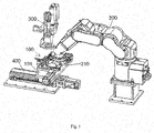
- Fig. 1 shows an illustrative perspective view of an assembly system according to an exemplary embodiment of the present disclosure
- Fig. 2 shows an illustrative perspective view of an assembly mechanism 100 of the assembly system as shown in Fig. 1
- Fig. 3 shows a schematic view illustrating a pressing tool 210 pressing and holding a first lead 10.
- the assembly system mainly comprises an assembly mechanism 100 mainly comprising a fixation device 130 for fixing a housing 30, a first lead assembly mechanism 110, 111, 112 provided at one side of the fixation device 130, and a second lead assembly mechanism 120, 121, 122 provided at other side of the fixation device 130.
- the first lead assembly mechanism 110,111, 112 is adapted to insert a first lead 10 into the housing 30
- the second lead assembly mechanism 120, 121, 122 is adapted to insert a second lead 20 into the housing 30, and the first lead 10 is inserted into the housing 30 before the second lead 20.
- the assembly system further comprises a pressing mechanism 200, 210 adapted to hold the first lead 10 inserted into the housing 30 at a correct installation position, so as to prevent the first lead 10 from being offset from its correct installation position and hindering the insertion of the second lead 20 during inserting the second lead 20.
- the pressing mechanism 200, 210 comprises a robot 200 and a pressing tool 210 mounted on the robot 200.
- the robot 200 is adapted to move the pressing tool 210, and the pressing tool 210 is adapted to press and hold the first lead 10, in order to hold the first lead 10 inserted into the housing 30 at its correct installation position.
- the pressing tool 210 is formed with a slot matched with a shape of the first lead 10 and adapted to hold the first lead 10 firmly.
- the assembly mechanism 100 further comprises a base 101, on which the first lead assembly mechanism 110, 111, 112, the second lead assembly mechanism 120, 121, 122 and the fixation device 130 are mounted.
- the first lead assembly mechanism 110, 111, 112 comprises a first lead clamp 110 adapted to clamp the first lead 10.
- the first lead clamp 110 is slidably mounted on the base 101 and is movable in a first horizontal direction X, so that the first lead 10 that is clamped on the first lead clamp 110 is inserted into the housing 30 fixed on the fixation device 130.
- the second lead assembly mechanism 120, 121, 122 comprises a second lead clamp 120 adapted to clamp the second lead 20.
- the second lead clamp 120 is slidably mounted on the base 101 and is movable in the first horizontal direction X, so that the second lead 20 that is clamped on the second lead clamp 120 is inserted into the housing 30 fixed on the fixation device 130.
- the first lead assembly mechanism 110, 111, 112 further comprises: a first moving device 111 adapted to be moved back and forth in the first horizontal direction X; and a first connecting device 112 slidably mounted on the first moving device 111 and adapted to be moved between an engagement position and a disengagement position.
- the first connecting device 112 When the first connecting device 112 is moved to the engagement position, the first connecting device 112 connects the first moving device 111 to the first lead clamp 110, so that the first lead clamp 110 is moved back and forth with the first moving device 111 in the first horizontal direction X; and when the first connecting device 112 is moved to the disengagement position, the first moving device 111 is disengaged from the first lead clamp 110, so that the first lead clamp 110 is no longer moved with the first moving device 111.
- the second lead assembly mechanism 120, 121, 122 further comprises: a second moving device 121 adapted to be moved back and forth in the first horizontal direction X; and a second connecting device 122 slidably mounted on the second moving device 121 and adapted to be moved between an engagement position and a disengagement position.
- the second connecting device 122 When the second connecting device 122 is moved to the engagement position, the second connecting device 122 connects the second moving device 121 to the second lead clamp 120, so that the second lead clamp 120 is moved back and forth with the second moving device 121 in the first horizontal direction X; and when the second connecting device 122 is moved to the disengagement position, the second moving device 121 is disengaged from the second lead clamp 120, so that the second lead clamp 120 is no longer moved with the second moving device 121.
- the first connecting device 112 and the second connecting device 122 are adapted to be moved in a second horizontal direction Y perpendicular to the first horizontal direction X.
- the first moving device 111 and the second moving device 121 may comprise an electrical cylinder or a servo drive, which may be adapted to control and adjust moving speed and accelerated speed of the first moving device 111 and the second moving device 121, thereby ensuring successful insertion of the first lead 10 and the second lead 20.
- the motion of the first connecting device 112 or the second connecting device 122 in the second horizontal direction Y is driven by a pneumatic cylinder.
- the assembly system further comprises a vision system 300 adapted to guide the insertions of the first lead 10 and the second lead 20.
- the vision system 300 is also adapted to detect depths by which the first lead 10 and the second lead 20 are inserted into the housing 30, so as to ensure the inserted depths of the first lead 10 and the second lead 20 are equal to a predetermined depth.
- the vision system 300 is also adapted to monitor whether the first lead 10 and the second lead 10 are properly inserted into the housing 30. When the vision system 300 detects that the first lead 10 or the second lead 20 is not properly inserted into the housing 30, the vision system 300 controls the assembly system to perform the operation of inserting the first lead 10 or the second lead 20 again.
- the vision system 300 determines that the first lead 10 has been properly inserted into the housing 30, the vision system 300 controls the pressing mechanism 200, 210 to hold the first lead 10 at its correct installation position.
- the assembly system further comprises a moving mechanism 400 adapted to be moved in the second horizontal direction Y.
- the assembly mechanism 100 is mounted on the moving mechanism 400.
- the moving mechanism 400 is adapted to move the assembly mechanism 100 mounted thereon from a loading station to an assembly station.
- the assembly mechanism 100 is at the loading station, the first lead 10, the second lead 20 and the housing 30 are loaded and fixed on the assembly mechanism 100; and when the assembly mechanism 100 is at the assembly station, the assembly mechanism 100 inserts the first lead 10 and the second lead 20 into the housing 30, respectively.
Landscapes
- Engineering & Computer Science (AREA)
- Manufacturing & Machinery (AREA)
- Automatic Assembly (AREA)
- Supply And Installment Of Electrical Components (AREA)
Abstract
Description
- This application claims the benefit of Chinese Patent Application No.
201711007228.3 filed on October 25, 2017 - Embodiments of the present disclosure relate to an assembly system, particularly, to an assembly system adapted to insert leads into a housing.
- In the technical field of manufacturing a connector, it is desired generally to insert a first lead and a second lead into a housing from both sides of the housing, respectively, and then to solder ends of the inserted first lead and second lead together. In order to ensure the soldering quality, the ends of the inserted first lead and second lead must be aligned and contacted with each other.
- In the relevant art, the operation of inserting the first lead and the second lead is usually performed manually. Generally, the worker needs to insert the first lead into the housing, and then insert the second lead into the housing. However, during inserting the second lead, the first lead that has been inserted into the housing tends to move. This causes the inserted first lead tending to be offset from its precise installation position, and may intervene and hinder the insertion of the second lead. Thus, such an arrangement decreases the efficiency of inserting the leads, and lowers the quality of the product.
- An objective of the present disclosure is to solve at least one aspect of the above mentioned problems and disadvantages occurred in the prior art.
- According to an aspect of the present disclosure, there is provided an assembly system comprising an assembly mechanism. The assembly mechanism comprises a fixation device adapted to fix a housing and a first lead assembly mechanism and a second lead assembly mechanism provided at both sides of the fixation device, respectively, wherein the first lead assembly mechanism is adapted to insert a first lead into the housing, the second lead assembly mechanism is adapted to insert a second lead into the housing, and the first lead is inserted into the housing before the second lead. The assembly system further comprises a pressing mechanism adapted to hold the first lead inserted into the housing at a correct installation position, so as to prevent the first lead from being offset from the correct installation position and hindering the insertion of the second lead during inserting the second lead.
- According to an exemplary embodiment of the present disclosure, the pressing mechanism comprises a robot and a pressing tool mounted on the robot, the robot being adapted to move the pressing tool, and the pressing tool being adapted to press and hold the first lead, in order to hold the first lead inserted into the housing at the correct installation position.
- According to a further exemplary embodiment of the present disclosure, the pressing tool is formed with a slot matched with a shape of the first lead and adapted to hold the first lead.
- According to a further exemplary embodiment of the present disclosure, the assembly mechanism comprises a base on which the first lead assembly mechanism, the second lead assembly mechanism and the fixation device are mounted.
- According to a further exemplary embodiment of the present disclosure, the first lead assembly mechanism comprises a first lead clamp adapted to clamp the first lead, the first lead clamp being slidably mounted on the base and being movable in a first horizontal direction, so that the first lead that is clamped on the first lead clamp is inserted into the housing fixed on the fixation device.
- According to a further exemplary embodiment of the present disclosure, the second lead assembly mechanism comprises a second lead clamp adapted to clamp the second lead, the second lead clamp being slidably mounted on the base and being movable in the first horizontal direction, so that the second lead that is clamped on the second lead clamp is inserted into the housing fixed on the fixation device.
- According to another exemplary embodiment of the present disclosure, the first lead assembly mechanism further comprises: a first moving device adapted to be moved back and forth in the first horizontal direction; and a first connecting device slidably mounted on the first moving device and adapted to be moved between an engagement position and a disengagement position, wherein when the first connecting device is moved to the engagement position, the first connecting device connects the first moving device to the first lead clamp, so that the first lead clamp is moved back and forth with the first moving device in the first horizontal direction; and when the first connecting device is moved to the disengagement position, the first moving device is disengaged from the first lead clamp, so that the first lead clamp is no longer moved with the first moving device.
- According to another exemplary embodiment of the present disclosure, the second lead assembly mechanism further comprises: a second moving device adapted to be moved back and forth in the first horizontal direction; and a second connecting device slidably mounted on the second moving device and adapted to be moved between an engagement position and a disengagement position, wherein when the second connecting device is moved to the engagement position, the second connecting device connects the second moving device to the second lead clamp, so that the second lead clamp is moved back and forth with the second moving device in the first horizontal direction; and when the second connecting device is moved to the disengagement position, the second moving device is disengaged from the second lead clamp, so that the second lead clamp is no longer moved with the second moving device.
- According to another exemplary embodiment of the present disclosure, the first connecting device and the second connecting device are adapted to be moved in a second horizontal direction perpendicular to the first horizontal direction.
- According to another exemplary embodiment of the present disclosure, the assembly system further comprises a vision system adapted to guide the insertions of the first lead and the second lead.
- According to another exemplary embodiment of the present disclosure, the vision system is further adapted to detect depths by which the first lead and the second lead are inserted into the housing.
- According to another exemplary embodiment of the present disclosure, the vision system is further adapted to monitor whether the first lead and the second lead are properly inserted into the housing. When the vision system detects that the first lead or the second lead is not properly inserted into the housing, the vision system controls the assembly system to insert the first lead or the second lead again.
- According to another exemplary embodiment of the present disclosure, when the vision system determines that the first lead has been properly inserted into the housing, the vision system controls the pressing mechanism to hold the first lead at the correct installation position.
- According to another exemplary embodiment of the present disclosure, after the first lead and the second lead have been properly inserted into the housing, ends of the first lead and the second lead are aligned and contacted with each other.
- According to another exemplary embodiment of the present disclosure, the assembly system further comprises a moving mechanism on which the assembly mechanism is mounted, the moving mechanism being adapted to move the assembly mechanism mounted thereon from a loading station to an assembly station; wherein when the assembly mechanism is at the loading station, the first lead, the second lead and the housing are loaded and fixed on the assembly mechanism; and when the assembly mechanism is at the assembly station, the assembly mechanism inserts the first lead and the second lead into the housing, respectively.
- In the above exemplary embodiments of the present disclosure, a set of assembly system automatically completes the task of assembling the first lead and the second lead into the housing, improving the efficiency of inserting the leads into the housing, and increasing the quality of the product..
- Other objectives and advantages of the present disclosure will become apparent from the following description of the present disclosure when taken in conjunction with the accompanying drawings, and may give a comprehensive understanding of the present disclosure.
- The above and other features of the present disclosure will become more apparent by describing in detail exemplary embodiments thereof with reference to the accompanying drawings, in which:
-
Fig. 1 shows an illustrative perspective view of an assembly system according to an exemplary embodiment of the present disclosure; -
Fig. 2 shows an illustrative perspective view of an assembly mechanism of the assembly system as shown inFig. 1 ; and -
Fig. 3 shows a schematic view illustrating a pressing tool pressing and holding a first lead. - The technical solution of the present disclosure will be described hereinafter in further detail with reference to the following embodiments, taken in conjunction with the accompanying drawings. In the specification, the same or similar reference numerals indicate the same or similar parts. The description of the embodiments of the present disclosure hereinafter with reference to the accompanying drawings is intended to explain the general inventive concept of the present disclosure, and should not be constructed as a limitation to the present disclosure.
- In addition, in the following detailed description, for the sake of explanation, numerous specific details are set forth in order to provide a thorough understanding of the disclosed embodiments. It will be apparent, however, one or more embodiments may also be practiced without these specific details. In other instances, well-known structures and devices are illustrated schematically in order to simplify the drawing.
- According to a general technical concept of the present disclosure, there is provided an assembly system comprising an assembly mechanism. The assembly mechanism comprises a fixation device for fixing a housing and a first lead assembly mechanism and a second lead assembly mechanism provided at both sides of the fixation device, respectively, wherein the first lead assembly mechanism is adapted to insert a first lead into the housing, the second lead assembly mechanism is adapted to insert a second lead into the housing, and the first lead is inserted into the housing before the second lead. The assembly system further comprises a pressing mechanism adapted to hold the first lead inserted into the housing at a correct installation position, so as to prevent the first lead from being offset from its correct installation position and hindering operation of inserting the second lead.
-
Fig. 1 shows an illustrative perspective view of an assembly system according to an exemplary embodiment of the present disclosure;Fig. 2 shows an illustrative perspective view of anassembly mechanism 100 of the assembly system as shown inFig. 1 ; andFig. 3 shows a schematic view illustrating apressing tool 210 pressing and holding afirst lead 10. - As shown in
Figs. 1-3 , in an illustrated embodiment, the assembly system mainly comprises anassembly mechanism 100 mainly comprising afixation device 130 for fixing ahousing 30, a firstlead assembly mechanism fixation device 130, and a secondlead assembly mechanism fixation device 130. - As shown in
Figs. 1-3 , in an illustrated embodiment, the first lead assembly mechanism 110,111, 112 is adapted to insert afirst lead 10 into thehousing 30, the secondlead assembly mechanism second lead 20 into thehousing 30, and thefirst lead 10 is inserted into thehousing 30 before thesecond lead 20. - As shown in
Figs. 1-3 , in an illustrated embodiment, the assembly system further comprises apressing mechanism first lead 10 inserted into thehousing 30 at a correct installation position, so as to prevent thefirst lead 10 from being offset from its correct installation position and hindering the insertion of thesecond lead 20 during inserting thesecond lead 20. - As shown in
Figs. 1-3 , in an illustrated embodiment, thepressing mechanism robot 200 and apressing tool 210 mounted on therobot 200. Therobot 200 is adapted to move thepressing tool 210, and thepressing tool 210 is adapted to press and hold thefirst lead 10, in order to hold thefirst lead 10 inserted into thehousing 30 at its correct installation position. - As shown in
Fig. 3 , in an illustrated embodiment, thepressing tool 210 is formed with a slot matched with a shape of thefirst lead 10 and adapted to hold thefirst lead 10 firmly. - As shown in
Figs. 1-3 , in an illustrated embodiment, theassembly mechanism 100 further comprises abase 101, on which the firstlead assembly mechanism lead assembly mechanism fixation device 130 are mounted. - As shown in
Figs. 1-3 , in an illustrated embodiment, the firstlead assembly mechanism first lead clamp 110 adapted to clamp thefirst lead 10. Thefirst lead clamp 110 is slidably mounted on thebase 101 and is movable in a first horizontal direction X, so that thefirst lead 10 that is clamped on thefirst lead clamp 110 is inserted into thehousing 30 fixed on thefixation device 130. - As shown in
Figs. 1-3 , in an illustrated embodiment, the secondlead assembly mechanism second lead clamp 120 adapted to clamp thesecond lead 20. Thesecond lead clamp 120 is slidably mounted on thebase 101 and is movable in the first horizontal direction X, so that thesecond lead 20 that is clamped on thesecond lead clamp 120 is inserted into thehousing 30 fixed on thefixation device 130. - As shown in
Figs. 1-3 , in an illustrated embodiment, the firstlead assembly mechanism device 111 adapted to be moved back and forth in the first horizontal direction X; and a first connectingdevice 112 slidably mounted on the first movingdevice 111 and adapted to be moved between an engagement position and a disengagement position. When the first connectingdevice 112 is moved to the engagement position, the first connectingdevice 112 connects the first movingdevice 111 to thefirst lead clamp 110, so that thefirst lead clamp 110 is moved back and forth with the first movingdevice 111 in the first horizontal direction X; and when the first connectingdevice 112 is moved to the disengagement position, the first movingdevice 111 is disengaged from thefirst lead clamp 110, so that thefirst lead clamp 110 is no longer moved with the first movingdevice 111. - As shown in
Figs. 1-3 , in an illustrated embodiment, the secondlead assembly mechanism device 121 adapted to be moved back and forth in the first horizontal direction X; and a second connectingdevice 122 slidably mounted on the second movingdevice 121 and adapted to be moved between an engagement position and a disengagement position. When the second connectingdevice 122 is moved to the engagement position, the second connectingdevice 122 connects the second movingdevice 121 to thesecond lead clamp 120, so that thesecond lead clamp 120 is moved back and forth with the second movingdevice 121 in the first horizontal direction X; and when the second connectingdevice 122 is moved to the disengagement position, the second movingdevice 121 is disengaged from thesecond lead clamp 120, so that thesecond lead clamp 120 is no longer moved with the second movingdevice 121. - As shown in
Figs. 1-3 , in an illustrated embodiment, the first connectingdevice 112 and the second connectingdevice 122 are adapted to be moved in a second horizontal direction Y perpendicular to the first horizontal direction X. - In an exemplary embodiment of the present disclosure, the first moving
device 111 and the second movingdevice 121 may comprise an electrical cylinder or a servo drive, which may be adapted to control and adjust moving speed and accelerated speed of the first movingdevice 111 and the second movingdevice 121, thereby ensuring successful insertion of thefirst lead 10 and thesecond lead 20. - In an exemplary embodiment of the present disclosure, the motion of the first connecting
device 112 or the second connectingdevice 122 in the second horizontal direction Y is driven by a pneumatic cylinder. - As shown in
Figs. 1-3 , in an illustrated embodiment, the assembly system further comprises avision system 300 adapted to guide the insertions of thefirst lead 10 and thesecond lead 20. - As shown in
Figs. 1-3 , in an illustrated embodiment, thevision system 300 is also adapted to detect depths by which thefirst lead 10 and thesecond lead 20 are inserted into thehousing 30, so as to ensure the inserted depths of thefirst lead 10 and thesecond lead 20 are equal to a predetermined depth. - As shown in
Figs. 1-3 , in an illustrated embodiment, thevision system 300 is also adapted to monitor whether thefirst lead 10 and thesecond lead 10 are properly inserted into thehousing 30. When thevision system 300 detects that thefirst lead 10 or thesecond lead 20 is not properly inserted into thehousing 30, thevision system 300 controls the assembly system to perform the operation of inserting thefirst lead 10 or thesecond lead 20 again. - As shown in
Figs. 1-3 , in an illustrated embodiment, when thevision system 300 determines that thefirst lead 10 has been properly inserted into thehousing 30, thevision system 300 controls thepressing mechanism first lead 10 at its correct installation position. - As shown in
Figs. 1-3 , in an illustrated embodiment, after thefirst lead 10 and thesecond lead 20 have been properly inserted into thehousing 30, ends of thefirst lead 10 and thesecond lead 20 are aligned and brought into contact with each other. - As shown in
Figs. 1-3 , in an illustrated embodiment, the assembly system further comprises a movingmechanism 400 adapted to be moved in the second horizontal direction Y. Theassembly mechanism 100 is mounted on the movingmechanism 400. The movingmechanism 400 is adapted to move theassembly mechanism 100 mounted thereon from a loading station to an assembly station. When theassembly mechanism 100 is at the loading station, thefirst lead 10, thesecond lead 20 and thehousing 30 are loaded and fixed on theassembly mechanism 100; and when theassembly mechanism 100 is at the assembly station, theassembly mechanism 100 inserts thefirst lead 10 and thesecond lead 20 into thehousing 30, respectively. - It should be appreciated by those skilled in the art that the above embodiments are intended to be illustrative, modifications may be made to the above embodiments by those skilled in the art, and structures described in various embodiments may be freely combined without having structural and principle conflict.
- Although the present disclosure has been described with reference to the attached drawings, the embodiments disclosed in the drawings are intended to illustrate the preferred embodiments of the present disclosure, but should not be constructed as a limitation to the present disclosure.
- Although some embodiments of the general concept of the present disclosure has been shown and described, it would be appreciated by those skilled in the art that modifications may be made to these embodiments without departing from the principle and spirit of the present disclosure, the scope of which is defined in the claims and their equivalents.
- It should be noted that term "comprising" or "including" should be understood as not excluding other elements or steps, and term "a" or "an" should be understood as not excluding plural elements or steps. Further, any reference numerals in claims should not be understood as a limitation to the present disclosure.
Claims (15)
- An assembly system, comprising:an assembly mechanism (100) comprising a fixation device (130) dapated to fix a housing (30) and a first lead assembly mechanism (110, 111, 112) and a second lead assembly mechanism (120, 121, 122) provided at both sides of the fixation device (130), respectively,the first lead assembly mechanism (110, 111, 112) being adapted to insert a first lead (10) into the housing (30), the second lead assembly mechanism (120, 121, 122) being adapted to insert a second lead (20) into the housing (30), and the first lead (10) being inserted into the housing (30) before the second lead (20),characterized in that, the assembly system further comprises a pressing mechanism (200, 210) adapted to hold the first lead (10) inserted into the housing (30) at a correct installation position, so as to prevent the first lead (10) from being offset from the correct installation position and hindering opration of inserting of the second lead (20).
- The assembly system according to claim 1, wherein,
the pressing mechanism (200, 210) comprises a robot (200) and a pressing tool (210) mounted on the robot (200), the robot (200) being adapted to move the pressing tool (210), and the pressing tool (210) being adapted to press and hold the first lead (10), in order to hold the first lead (10) inserted into the housing (30) at the correct installation position. - The assembly system according to claim 2, wherein,
the pressing tool (210) is formed with a slot matched with a shape of the first lead (10) and adapted to hold the first lead (10). - The assembly system according to claim 1, wherein,
the assembly mechanism (100)comprises a base (101) on which the first lead assembly mechanism, the second lead assembly mechanism and the fixation device are mounted. - The assembly system according to claim 4, wherein,
the first lead assembly mechanism (110, 111, 112) comprises a first lead clamp (110) adapted to clamp the first lead (10), the first lead clamp (110) being slidably mounted on the base (101) and being movable in a first horizontal direction (X), so that the first lead (10) that is clamped on the first lead clamp (110) is inserted into the housing (30) fixed on the fixation device (130). - The assembly system according to claim 5, wherein,
the second lead assembly mechanism (120, 121, 122) comprises a second lead clamp (120) adapted to clamp the second lead (20), the second lead clamp (120) being slidably mounted on the base (101) and being movable in the first horizontal direction (X), so that the second lead (20) that is clamped on the second lead clamp (120) is inserted into the housing (30) fixed on the fixation device (130). - The assembly system according to claim 6, wherein, the first lead assembly mechanism (110, 111, 112) further comprises:a first moving device (111) adapted to be moved back and forth in the first horizontal direction (X); anda first connecting device (112) slidably mounted on the first moving device (111) and adapted to be moved between an engagement position and a disengagement position,wherein when the first connecting device (112) is moved to the engagement position, the first connecting device (112) connects the first moving device (111) to the first lead clamp (110), so that the first lead clamp (110) is moved back and forth with the first moving device (111) in the first horizontal direction (X); andwhen the first connecting device (112) is moved to the disengagement position, the first moving device (111) is disengaged from the first lead clamp (110), so that the first lead clamp (110) is no longer moved with the first moving device (111).
- The assembly system according to claim 7, wherein, the second lead assembly mechanism (120, 121, 122) further comprises:a second moving device (121) adapted to be moved back and forth in the first horizontal direction (X); anda second connecting device (122) slidably mounted on the second moving devic (122) e and adapted to be moved between an engagement position and a disengagement position,wherein when the second connecting device (122) is moved to the engagement position, the second connecting device (122) connects the second moving device (121) to the second lead clamp (120), so that the second lead clamp (120) is moved back and forth with the second moving device (121) in the first horizontal direction (X); andwhen the second connecting device (122) is moved to the disengagement position, the second moving device (121) is disengaged from the second lead clamp (120), so that the second lead clamp (120) is no longer moved with the second moving device (121).
- The assembly system according to claim 8, wherein,
the first connecting device (112) and the second connecting device (122) are adapted to be moved in a second horizontal direction ()Y perpendicular to the first horizontal direction (X). - The assembly system according to claim 1, wherein,
the assembly system further comprises a vision system (300) adapted to guide the insertions of the first lead (10) and the second lead (20). - The assembly system according to claim 10, wherein,
the vision system (300) is further adapted to detect depths by which the first lead (10) and the second lead (20) are inserted into the housing (30). - The assembly system according to claim 10, wherein,
the vision system (300) is further adapted to monitor whether the first lead (10) and the second lead (20) are properly inserted into the housing; and
wherein when the vision system (300) detects that the first lead (10) or the second lead (20) is not properly inserted into the housing (30), the vision system (300) controls the assembly system to perform the operation of inserting the first lead (10) or the second lead (20) again. - The assembly system according to claim 12, wherein,
when the vision system (300) determines that the first lead (10) has been properly inserted into the housing (30), the vision system (300) controls the pressing mechanism (200, 210) to hold the first lead (10) at the correct installation position. - The assembly system according to claim 1, wherein,
after the first lead (10) and the second lead (20) have been properly inserted into the housing (30), ends of the first lead (10) and the second lead (20) are aligned and brought into contact with each other. - The assembly system according to claim 1, wherein,
the assembly system further comprises a moving mechanism (400) on which the assembly mechanism (100) is mounted, the moving mechanism (400) being adapted to move the assembly mechanism (100) mounted thereon from a loading station to an assembly station;
wherein when the assembly mechanism (100) is at the loading station, the first lead (10), the second lead (20) and the housing (30) are loaded and fixed on the assembly mechanism (100); and
when the assembly mechanism (100) is at the assembly station, the assembly mechanism (100) inserts the first lead (10) and the second lead (20) into the housing (30), respectively.
Applications Claiming Priority (1)
| Application Number | Priority Date | Filing Date | Title |
|---|---|---|---|
| CN201711007228.3A CN109713544B (en) | 2017-10-25 | 2017-10-25 | Assembly system |
Publications (2)
| Publication Number | Publication Date |
|---|---|
| EP3477798A1 true EP3477798A1 (en) | 2019-05-01 |
| EP3477798B1 EP3477798B1 (en) | 2022-03-23 |
Family
ID=63965400
Family Applications (1)
| Application Number | Title | Priority Date | Filing Date |
|---|---|---|---|
| EP18202092.5A Active EP3477798B1 (en) | 2017-10-25 | 2018-10-23 | Assembly system |
Country Status (2)
| Country | Link |
|---|---|
| EP (1) | EP3477798B1 (en) |
| CN (1) | CN109713544B (en) |
Cited By (4)
| Publication number | Priority date | Publication date | Assignee | Title |
|---|---|---|---|---|
| CN110311285A (en) * | 2019-07-10 | 2019-10-08 | 江苏倚信自动化设备有限公司 | A kind of servo rotation contact pin apparatus |
| CN112421328A (en) * | 2020-11-10 | 2021-02-26 | 常德富博智能科技有限公司 | Automatic equipment for automatically mounting shielding case on apple head connector |
| EP3944418A1 (en) | 2020-07-23 | 2022-01-26 | MD Elektronik GmbH | Soldering aid for connecting a cable with a circuit board; cable; circuit board; assembly; method |
| EP3944417A1 (en) | 2020-07-23 | 2022-01-26 | MD Elektronik GmbH | Soldering aid and method for attaching a cable to a conductor surface |
Citations (5)
| Publication number | Priority date | Publication date | Assignee | Title |
|---|---|---|---|---|
| US4910859A (en) * | 1984-04-06 | 1990-03-27 | Holcomb Gregory W | Circuit assembly system |
| EP1236563A1 (en) * | 2001-02-16 | 2002-09-04 | Hirschmann Austria GmbH | Electrical connection by ultrasonic welding |
| EP1619759A1 (en) * | 2004-07-19 | 2006-01-25 | Saint-Gobain Glass France | Electrical connection with cross-section transition, procedure and manufacturing and laminated glass with such connection |
| US20140109385A1 (en) * | 2012-10-22 | 2014-04-24 | Tyco Electronics Corporation | Wire sorting fixture and method of sorting wires |
| CN105817851A (en) * | 2015-01-07 | 2016-08-03 | 泰科电子(上海)有限公司 | Automatic assembly system and method |
Family Cites Families (4)
| Publication number | Priority date | Publication date | Assignee | Title |
|---|---|---|---|---|
| US20020076990A1 (en) * | 2000-12-15 | 2002-06-20 | Sumitomo Wiring Systems Ltd. | Apparatus for processing a stacked-type connector of a wire harness, a housing holder, apparatus and method and for stacking housings of a stacked-type connectors, and apparatus for pressing a joint portion of stacked-type connector |
| WO2011096160A1 (en) * | 2010-02-02 | 2011-08-11 | パナソニック株式会社 | Battery pack and manufacturing method therefor |
| CN204633115U (en) * | 2015-06-10 | 2015-09-09 | 汪全鹏 | The pre-tin guillotine of a kind of split conductor peeling |
| JP6643064B2 (en) * | 2015-10-29 | 2020-02-12 | ヒロセ電機株式会社 | Coaxial cable connector, coaxial cable connector with carrier, and method of manufacturing coaxial cable connector |
-
2017
- 2017-10-25 CN CN201711007228.3A patent/CN109713544B/en active Active
-
2018
- 2018-10-23 EP EP18202092.5A patent/EP3477798B1/en active Active
Patent Citations (5)
| Publication number | Priority date | Publication date | Assignee | Title |
|---|---|---|---|---|
| US4910859A (en) * | 1984-04-06 | 1990-03-27 | Holcomb Gregory W | Circuit assembly system |
| EP1236563A1 (en) * | 2001-02-16 | 2002-09-04 | Hirschmann Austria GmbH | Electrical connection by ultrasonic welding |
| EP1619759A1 (en) * | 2004-07-19 | 2006-01-25 | Saint-Gobain Glass France | Electrical connection with cross-section transition, procedure and manufacturing and laminated glass with such connection |
| US20140109385A1 (en) * | 2012-10-22 | 2014-04-24 | Tyco Electronics Corporation | Wire sorting fixture and method of sorting wires |
| CN105817851A (en) * | 2015-01-07 | 2016-08-03 | 泰科电子(上海)有限公司 | Automatic assembly system and method |
Cited By (9)
| Publication number | Priority date | Publication date | Assignee | Title |
|---|---|---|---|---|
| CN110311285A (en) * | 2019-07-10 | 2019-10-08 | 江苏倚信自动化设备有限公司 | A kind of servo rotation contact pin apparatus |
| CN110311285B (en) * | 2019-07-10 | 2024-05-10 | 江苏倚信自动化设备有限公司 | Servo rotary pin inserting device |
| EP3944418A1 (en) | 2020-07-23 | 2022-01-26 | MD Elektronik GmbH | Soldering aid for connecting a cable with a circuit board; cable; circuit board; assembly; method |
| EP3944417A1 (en) | 2020-07-23 | 2022-01-26 | MD Elektronik GmbH | Soldering aid and method for attaching a cable to a conductor surface |
| DE102020119422A1 (en) | 2020-07-23 | 2022-01-27 | Md Elektronik Gmbh | Soldering accessory for connecting a cable to a printed circuit board; Cable; circuit board; Module; proceedings |
| DE102020119423A1 (en) | 2020-07-23 | 2022-01-27 | Md Elektronik Gmbh | Soldering aid and method for attaching a cable to a conductor surface |
| US11729916B2 (en) | 2020-07-23 | 2023-08-15 | Md Elektronik Gmbh | Soldering aid for connecting a cable to a printed circuit board |
| US11843191B2 (en) | 2020-07-23 | 2023-12-12 | Md Elektronik Gmbh | Soldering aid and method for attaching a cable to a conductor area |
| CN112421328A (en) * | 2020-11-10 | 2021-02-26 | 常德富博智能科技有限公司 | Automatic equipment for automatically mounting shielding case on apple head connector |
Also Published As
| Publication number | Publication date |
|---|---|
| CN109713544A (en) | 2019-05-03 |
| EP3477798B1 (en) | 2022-03-23 |
| CN109713544B (en) | 2021-02-26 |
Similar Documents
| Publication | Publication Date | Title |
|---|---|---|
| EP3477798A1 (en) | Assembly system | |
| US9750170B2 (en) | Automatic assembling system | |
| US10993360B2 (en) | Assembly system | |
| US11324124B2 (en) | Lead component clinching and mounting method | |
| EP3015219A1 (en) | Automatic component loading system | |
| US11641086B2 (en) | Method for automatically mounting a connector-housing | |
| CN105817851B (en) | Automatic setup system and method | |
| US11058040B2 (en) | Operation checking device of electronic mounting machine | |
| JP2018192582A (en) | Seal ring attachment device | |
| EP3639989A1 (en) | Assembly apparatus and structure fabricating method | |
| JP2020186122A (en) | Transfer device of work transport pallet | |
| EP3550950B1 (en) | Operation machine | |
| WO2015004813A1 (en) | Method of mounting component onto substrate in component mounting device and component mounting device | |
| KR100420558B1 (en) | Yoke Clearance and Position Control Device for Universal Joint | |
| US10617049B2 (en) | Component mounting device and gripping members | |
| CN108543845B (en) | Bending Machine | |
| CN113170608B (en) | Work head and work machine | |
| CN116386960B (en) | Shielded wire harness assembling apparatus and shielded wire harness assembling method | |
| JP2001160472A (en) | Fastening apparatus of wire with terminal in an automatic terminal inserter and its fastening method | |
| CN216376491U (en) | Carrying device and processing system | |
| CN221337610U (en) | CNC processing clamping device | |
| WO2023145000A1 (en) | Jig and connector mounting method | |
| US11769978B2 (en) | Assembly system | |
| CN210702162U (en) | Core penetrating positioning device and automatic pipe fitting stamping equipment | |
| US11618179B2 (en) | Device for inserting a first ram or a second ram in an alternating manner |
Legal Events
| Date | Code | Title | Description |
|---|---|---|---|
| PUAI | Public reference made under article 153(3) epc to a published international application that has entered the european phase |
Free format text: ORIGINAL CODE: 0009012 |
|
| STAA | Information on the status of an ep patent application or granted ep patent |
Free format text: STATUS: THE APPLICATION HAS BEEN PUBLISHED |
|
| AK | Designated contracting states |
Kind code of ref document: A1 Designated state(s): AL AT BE BG CH CY CZ DE DK EE ES FI FR GB GR HR HU IE IS IT LI LT LU LV MC MK MT NL NO PL PT RO RS SE SI SK SM TR |
|
| AX | Request for extension of the european patent |
Extension state: BA ME |
|
| STAA | Information on the status of an ep patent application or granted ep patent |
Free format text: STATUS: REQUEST FOR EXAMINATION WAS MADE |
|
| 17P | Request for examination filed |
Effective date: 20191025 |
|
| RBV | Designated contracting states (corrected) |
Designated state(s): AL AT BE BG CH CY CZ DE DK EE ES FI FR GB GR HR HU IE IS IT LI LT LU LV MC MK MT NL NO PL PT RO RS SE SI SK SM TR |
|
| STAA | Information on the status of an ep patent application or granted ep patent |
Free format text: STATUS: EXAMINATION IS IN PROGRESS |
|
| 17Q | First examination report despatched |
Effective date: 20210127 |
|
| REG | Reference to a national code |
Ref country code: DE Ref legal event code: R079 Ref document number: 602018032568 Country of ref document: DE Free format text: PREVIOUS MAIN CLASS: H01R0043200000 Ipc: H01R0043260000 |
|
| GRAP | Despatch of communication of intention to grant a patent |
Free format text: ORIGINAL CODE: EPIDOSNIGR1 |
|
| STAA | Information on the status of an ep patent application or granted ep patent |
Free format text: STATUS: GRANT OF PATENT IS INTENDED |
|
| RIC1 | Information provided on ipc code assigned before grant |
Ipc: H01R 43/26 20060101AFI20211005BHEP |
|
| INTG | Intention to grant announced |
Effective date: 20211025 |
|
| GRAS | Grant fee paid |
Free format text: ORIGINAL CODE: EPIDOSNIGR3 |
|
| GRAA | (expected) grant |
Free format text: ORIGINAL CODE: 0009210 |
|
| STAA | Information on the status of an ep patent application or granted ep patent |
Free format text: STATUS: THE PATENT HAS BEEN GRANTED |
|
| AK | Designated contracting states |
Kind code of ref document: B1 Designated state(s): AL AT BE BG CH CY CZ DE DK EE ES FI FR GB GR HR HU IE IS IT LI LT LU LV MC MK MT NL NO PL PT RO RS SE SI SK SM TR |
|
| REG | Reference to a national code |
Ref country code: GB Ref legal event code: FG4D |
|
| REG | Reference to a national code |
Ref country code: CH Ref legal event code: EP |
|
| REG | Reference to a national code |
Ref country code: IE Ref legal event code: FG4D |
|
| REG | Reference to a national code |
Ref country code: DE Ref legal event code: R096 Ref document number: 602018032568 Country of ref document: DE |
|
| REG | Reference to a national code |
Ref country code: AT Ref legal event code: REF Ref document number: 1478097 Country of ref document: AT Kind code of ref document: T Effective date: 20220415 |
|
| REG | Reference to a national code |
Ref country code: LT Ref legal event code: MG9D |
|
| REG | Reference to a national code |
Ref country code: NL Ref legal event code: MP Effective date: 20220323 |
|
| PG25 | Lapsed in a contracting state [announced via postgrant information from national office to epo] |
Ref country code: SE Free format text: LAPSE BECAUSE OF FAILURE TO SUBMIT A TRANSLATION OF THE DESCRIPTION OR TO PAY THE FEE WITHIN THE PRESCRIBED TIME-LIMIT Effective date: 20220323 Ref country code: RS Free format text: LAPSE BECAUSE OF FAILURE TO SUBMIT A TRANSLATION OF THE DESCRIPTION OR TO PAY THE FEE WITHIN THE PRESCRIBED TIME-LIMIT Effective date: 20220323 Ref country code: NO Free format text: LAPSE BECAUSE OF FAILURE TO SUBMIT A TRANSLATION OF THE DESCRIPTION OR TO PAY THE FEE WITHIN THE PRESCRIBED TIME-LIMIT Effective date: 20220623 Ref country code: LT Free format text: LAPSE BECAUSE OF FAILURE TO SUBMIT A TRANSLATION OF THE DESCRIPTION OR TO PAY THE FEE WITHIN THE PRESCRIBED TIME-LIMIT Effective date: 20220323 Ref country code: HR Free format text: LAPSE BECAUSE OF FAILURE TO SUBMIT A TRANSLATION OF THE DESCRIPTION OR TO PAY THE FEE WITHIN THE PRESCRIBED TIME-LIMIT Effective date: 20220323 Ref country code: BG Free format text: LAPSE BECAUSE OF FAILURE TO SUBMIT A TRANSLATION OF THE DESCRIPTION OR TO PAY THE FEE WITHIN THE PRESCRIBED TIME-LIMIT Effective date: 20220623 |
|
| REG | Reference to a national code |
Ref country code: AT Ref legal event code: MK05 Ref document number: 1478097 Country of ref document: AT Kind code of ref document: T Effective date: 20220323 |
|
| PG25 | Lapsed in a contracting state [announced via postgrant information from national office to epo] |
Ref country code: LV Free format text: LAPSE BECAUSE OF FAILURE TO SUBMIT A TRANSLATION OF THE DESCRIPTION OR TO PAY THE FEE WITHIN THE PRESCRIBED TIME-LIMIT Effective date: 20220323 Ref country code: GR Free format text: LAPSE BECAUSE OF FAILURE TO SUBMIT A TRANSLATION OF THE DESCRIPTION OR TO PAY THE FEE WITHIN THE PRESCRIBED TIME-LIMIT Effective date: 20220624 Ref country code: FI Free format text: LAPSE BECAUSE OF FAILURE TO SUBMIT A TRANSLATION OF THE DESCRIPTION OR TO PAY THE FEE WITHIN THE PRESCRIBED TIME-LIMIT Effective date: 20220323 |
|
| PG25 | Lapsed in a contracting state [announced via postgrant information from national office to epo] |
Ref country code: NL Free format text: LAPSE BECAUSE OF FAILURE TO SUBMIT A TRANSLATION OF THE DESCRIPTION OR TO PAY THE FEE WITHIN THE PRESCRIBED TIME-LIMIT Effective date: 20220323 |
|
| PG25 | Lapsed in a contracting state [announced via postgrant information from national office to epo] |
Ref country code: SM Free format text: LAPSE BECAUSE OF FAILURE TO SUBMIT A TRANSLATION OF THE DESCRIPTION OR TO PAY THE FEE WITHIN THE PRESCRIBED TIME-LIMIT Effective date: 20220323 Ref country code: SK Free format text: LAPSE BECAUSE OF FAILURE TO SUBMIT A TRANSLATION OF THE DESCRIPTION OR TO PAY THE FEE WITHIN THE PRESCRIBED TIME-LIMIT Effective date: 20220323 Ref country code: RO Free format text: LAPSE BECAUSE OF FAILURE TO SUBMIT A TRANSLATION OF THE DESCRIPTION OR TO PAY THE FEE WITHIN THE PRESCRIBED TIME-LIMIT Effective date: 20220323 Ref country code: PT Free format text: LAPSE BECAUSE OF FAILURE TO SUBMIT A TRANSLATION OF THE DESCRIPTION OR TO PAY THE FEE WITHIN THE PRESCRIBED TIME-LIMIT Effective date: 20220725 Ref country code: ES Free format text: LAPSE BECAUSE OF FAILURE TO SUBMIT A TRANSLATION OF THE DESCRIPTION OR TO PAY THE FEE WITHIN THE PRESCRIBED TIME-LIMIT Effective date: 20220323 Ref country code: EE Free format text: LAPSE BECAUSE OF FAILURE TO SUBMIT A TRANSLATION OF THE DESCRIPTION OR TO PAY THE FEE WITHIN THE PRESCRIBED TIME-LIMIT Effective date: 20220323 Ref country code: CZ Free format text: LAPSE BECAUSE OF FAILURE TO SUBMIT A TRANSLATION OF THE DESCRIPTION OR TO PAY THE FEE WITHIN THE PRESCRIBED TIME-LIMIT Effective date: 20220323 Ref country code: AT Free format text: LAPSE BECAUSE OF FAILURE TO SUBMIT A TRANSLATION OF THE DESCRIPTION OR TO PAY THE FEE WITHIN THE PRESCRIBED TIME-LIMIT Effective date: 20220323 |
|
| PG25 | Lapsed in a contracting state [announced via postgrant information from national office to epo] |
Ref country code: PL Free format text: LAPSE BECAUSE OF FAILURE TO SUBMIT A TRANSLATION OF THE DESCRIPTION OR TO PAY THE FEE WITHIN THE PRESCRIBED TIME-LIMIT Effective date: 20220323 Ref country code: IS Free format text: LAPSE BECAUSE OF FAILURE TO SUBMIT A TRANSLATION OF THE DESCRIPTION OR TO PAY THE FEE WITHIN THE PRESCRIBED TIME-LIMIT Effective date: 20220723 Ref country code: AL Free format text: LAPSE BECAUSE OF FAILURE TO SUBMIT A TRANSLATION OF THE DESCRIPTION OR TO PAY THE FEE WITHIN THE PRESCRIBED TIME-LIMIT Effective date: 20220323 |
|
| REG | Reference to a national code |
Ref country code: DE Ref legal event code: R097 Ref document number: 602018032568 Country of ref document: DE |
|
| PLBE | No opposition filed within time limit |
Free format text: ORIGINAL CODE: 0009261 |
|
| STAA | Information on the status of an ep patent application or granted ep patent |
Free format text: STATUS: NO OPPOSITION FILED WITHIN TIME LIMIT |
|
| PG25 | Lapsed in a contracting state [announced via postgrant information from national office to epo] |
Ref country code: DK Free format text: LAPSE BECAUSE OF FAILURE TO SUBMIT A TRANSLATION OF THE DESCRIPTION OR TO PAY THE FEE WITHIN THE PRESCRIBED TIME-LIMIT Effective date: 20220323 |
|
| 26N | No opposition filed |
Effective date: 20230102 |
|
| PG25 | Lapsed in a contracting state [announced via postgrant information from national office to epo] |
Ref country code: SI Free format text: LAPSE BECAUSE OF FAILURE TO SUBMIT A TRANSLATION OF THE DESCRIPTION OR TO PAY THE FEE WITHIN THE PRESCRIBED TIME-LIMIT Effective date: 20220323 Ref country code: MC Free format text: LAPSE BECAUSE OF FAILURE TO SUBMIT A TRANSLATION OF THE DESCRIPTION OR TO PAY THE FEE WITHIN THE PRESCRIBED TIME-LIMIT Effective date: 20220323 |
|
| REG | Reference to a national code |
Ref country code: CH Ref legal event code: PL |
|
| REG | Reference to a national code |
Ref country code: BE Ref legal event code: MM Effective date: 20221031 |
|
| GBPC | Gb: european patent ceased through non-payment of renewal fee |
Effective date: 20221023 |
|
| PG25 | Lapsed in a contracting state [announced via postgrant information from national office to epo] |
Ref country code: LU Free format text: LAPSE BECAUSE OF NON-PAYMENT OF DUE FEES Effective date: 20221023 |
|
| PG25 | Lapsed in a contracting state [announced via postgrant information from national office to epo] |
Ref country code: LI Free format text: LAPSE BECAUSE OF NON-PAYMENT OF DUE FEES Effective date: 20221031 Ref country code: IT Free format text: LAPSE BECAUSE OF FAILURE TO SUBMIT A TRANSLATION OF THE DESCRIPTION OR TO PAY THE FEE WITHIN THE PRESCRIBED TIME-LIMIT Effective date: 20220323 Ref country code: FR Free format text: LAPSE BECAUSE OF NON-PAYMENT OF DUE FEES Effective date: 20221031 Ref country code: CH Free format text: LAPSE BECAUSE OF NON-PAYMENT OF DUE FEES Effective date: 20221031 |
|
| PG25 | Lapsed in a contracting state [announced via postgrant information from national office to epo] |
Ref country code: BE Free format text: LAPSE BECAUSE OF NON-PAYMENT OF DUE FEES Effective date: 20221031 |
|
| PG25 | Lapsed in a contracting state [announced via postgrant information from national office to epo] |
Ref country code: IE Free format text: LAPSE BECAUSE OF NON-PAYMENT OF DUE FEES Effective date: 20221023 Ref country code: GB Free format text: LAPSE BECAUSE OF NON-PAYMENT OF DUE FEES Effective date: 20221023 |
|
| PGFP | Annual fee paid to national office [announced via postgrant information from national office to epo] |
Ref country code: DE Payment date: 20230830 Year of fee payment: 6 |
|
| PG25 | Lapsed in a contracting state [announced via postgrant information from national office to epo] |
Ref country code: HU Free format text: LAPSE BECAUSE OF FAILURE TO SUBMIT A TRANSLATION OF THE DESCRIPTION OR TO PAY THE FEE WITHIN THE PRESCRIBED TIME-LIMIT; INVALID AB INITIO Effective date: 20181023 |
|
| PG25 | Lapsed in a contracting state [announced via postgrant information from national office to epo] |
Ref country code: CY Free format text: LAPSE BECAUSE OF FAILURE TO SUBMIT A TRANSLATION OF THE DESCRIPTION OR TO PAY THE FEE WITHIN THE PRESCRIBED TIME-LIMIT Effective date: 20220323 |
|
| PG25 | Lapsed in a contracting state [announced via postgrant information from national office to epo] |
Ref country code: MK Free format text: LAPSE BECAUSE OF FAILURE TO SUBMIT A TRANSLATION OF THE DESCRIPTION OR TO PAY THE FEE WITHIN THE PRESCRIBED TIME-LIMIT Effective date: 20220323 |
|
| PG25 | Lapsed in a contracting state [announced via postgrant information from national office to epo] |
Ref country code: TR Free format text: LAPSE BECAUSE OF FAILURE TO SUBMIT A TRANSLATION OF THE DESCRIPTION OR TO PAY THE FEE WITHIN THE PRESCRIBED TIME-LIMIT Effective date: 20220323 |
|
| REG | Reference to a national code |
Ref country code: DE Ref legal event code: R081 Ref document number: 602018032568 Country of ref document: DE Owner name: TYCO ELECTRONICS (SHANGHAI) CO., LTD., CN Free format text: FORMER OWNERS: KUNSHAN LEAGUE AUTOMECHANISM CO., LTD., KUNSHAN, JIANGSU, CN; MEAS FRANCE, TOULOUSE, FR; SHENZHEN AMI TECHNOLOGY CO., LTD., SHENZHEN, GUANGDONG, CN; TE CONNECTIVITY CORPORATION, BERWYN, PA, US; TE CONNECTIVITY GERMANY GMBH, 64625 BENSHEIM, DE; TYCO ELECTRONICS (SHANGHAI) CO., LTD., SHANGHAI, CN Ref country code: DE Ref legal event code: R081 Ref document number: 602018032568 Country of ref document: DE Owner name: TE CONNECTIVITY SOLUTIONS GMBH, CH Free format text: FORMER OWNERS: KUNSHAN LEAGUE AUTOMECHANISM CO., LTD., KUNSHAN, JIANGSU, CN; MEAS FRANCE, TOULOUSE, FR; SHENZHEN AMI TECHNOLOGY CO., LTD., SHENZHEN, GUANGDONG, CN; TE CONNECTIVITY CORPORATION, BERWYN, PA, US; TE CONNECTIVITY GERMANY GMBH, 64625 BENSHEIM, DE; TYCO ELECTRONICS (SHANGHAI) CO., LTD., SHANGHAI, CN Ref country code: DE Ref legal event code: R081 Ref document number: 602018032568 Country of ref document: DE Owner name: TE CONNECTIVITY GERMANY GMBH, DE Free format text: FORMER OWNERS: KUNSHAN LEAGUE AUTOMECHANISM CO., LTD., KUNSHAN, JIANGSU, CN; MEAS FRANCE, TOULOUSE, FR; SHENZHEN AMI TECHNOLOGY CO., LTD., SHENZHEN, GUANGDONG, CN; TE CONNECTIVITY CORPORATION, BERWYN, PA, US; TE CONNECTIVITY GERMANY GMBH, 64625 BENSHEIM, DE; TYCO ELECTRONICS (SHANGHAI) CO., LTD., SHANGHAI, CN Ref country code: DE Ref legal event code: R081 Ref document number: 602018032568 Country of ref document: DE Owner name: SHENZHEN AMI TECHNOLOGY CO., LTD., SHENZHEN, CN Free format text: FORMER OWNERS: KUNSHAN LEAGUE AUTOMECHANISM CO., LTD., KUNSHAN, JIANGSU, CN; MEAS FRANCE, TOULOUSE, FR; SHENZHEN AMI TECHNOLOGY CO., LTD., SHENZHEN, GUANGDONG, CN; TE CONNECTIVITY CORPORATION, BERWYN, PA, US; TE CONNECTIVITY GERMANY GMBH, 64625 BENSHEIM, DE; TYCO ELECTRONICS (SHANGHAI) CO., LTD., SHANGHAI, CN Ref country code: DE Ref legal event code: R081 Ref document number: 602018032568 Country of ref document: DE Owner name: MEAS FRANCE, FR Free format text: FORMER OWNERS: KUNSHAN LEAGUE AUTOMECHANISM CO., LTD., KUNSHAN, JIANGSU, CN; MEAS FRANCE, TOULOUSE, FR; SHENZHEN AMI TECHNOLOGY CO., LTD., SHENZHEN, GUANGDONG, CN; TE CONNECTIVITY CORPORATION, BERWYN, PA, US; TE CONNECTIVITY GERMANY GMBH, 64625 BENSHEIM, DE; TYCO ELECTRONICS (SHANGHAI) CO., LTD., SHANGHAI, CN Ref country code: DE Ref legal event code: R081 Ref document number: 602018032568 Country of ref document: DE Owner name: KUNSHAN LEAGUE AUTOMECHANISM CO., LTD., KUNSHA, CN Free format text: FORMER OWNERS: KUNSHAN LEAGUE AUTOMECHANISM CO., LTD., KUNSHAN, JIANGSU, CN; MEAS FRANCE, TOULOUSE, FR; SHENZHEN AMI TECHNOLOGY CO., LTD., SHENZHEN, GUANGDONG, CN; TE CONNECTIVITY CORPORATION, BERWYN, PA, US; TE CONNECTIVITY GERMANY GMBH, 64625 BENSHEIM, DE; TYCO ELECTRONICS (SHANGHAI) CO., LTD., SHANGHAI, CN |