EP3477790A2 - Device for use in the ex area - Google Patents
Device for use in the ex area Download PDFInfo
- Publication number
- EP3477790A2 EP3477790A2 EP18000811.2A EP18000811A EP3477790A2 EP 3477790 A2 EP3477790 A2 EP 3477790A2 EP 18000811 A EP18000811 A EP 18000811A EP 3477790 A2 EP3477790 A2 EP 3477790A2
- Authority
- EP
- European Patent Office
- Prior art keywords
- power supply
- supply part
- contacts
- circuit
- switches
- Prior art date
- Legal status (The legal status is an assumption and is not a legal conclusion. Google has not performed a legal analysis and makes no representation as to the accuracy of the status listed.)
- Granted
Links
- 238000000926 separation method Methods 0.000 claims abstract 2
- 231100001261 hazardous Toxicity 0.000 claims description 5
- 230000001939 inductive effect Effects 0.000 claims description 3
- 238000011144 upstream manufacturing Methods 0.000 claims description 2
- 238000013459 approach Methods 0.000 description 5
- 238000013461 design Methods 0.000 description 3
- 239000012777 electrically insulating material Substances 0.000 description 3
- 239000002184 metal Substances 0.000 description 3
- 229910052751 metal Inorganic materials 0.000 description 3
- 238000000034 method Methods 0.000 description 3
- 238000012544 monitoring process Methods 0.000 description 3
- 230000001960 triggered effect Effects 0.000 description 3
- XEEYBQQBJWHFJM-UHFFFAOYSA-N Iron Chemical compound [Fe] XEEYBQQBJWHFJM-UHFFFAOYSA-N 0.000 description 2
- 239000002360 explosive Substances 0.000 description 2
- 238000009434 installation Methods 0.000 description 2
- 230000002093 peripheral effect Effects 0.000 description 2
- 230000007175 bidirectional communication Effects 0.000 description 1
- 230000006854 communication Effects 0.000 description 1
- 238000004891 communication Methods 0.000 description 1
- 238000001514 detection method Methods 0.000 description 1
- 238000007599 discharging Methods 0.000 description 1
- 230000005284 excitation Effects 0.000 description 1
- 238000003780 insertion Methods 0.000 description 1
- 230000037431 insertion Effects 0.000 description 1
- -1 iron Chemical class 0.000 description 1
- 229910052742 iron Inorganic materials 0.000 description 1
- 238000002955 isolation Methods 0.000 description 1
- 239000007769 metal material Substances 0.000 description 1
- 150000002739 metals Chemical class 0.000 description 1
- 230000003278 mimic effect Effects 0.000 description 1
- 238000007747 plating Methods 0.000 description 1
- 210000002105 tongue Anatomy 0.000 description 1
Images


Classifications
-
- H—ELECTRICITY
- H01—ELECTRIC ELEMENTS
- H01R—ELECTRICALLY-CONDUCTIVE CONNECTIONS; STRUCTURAL ASSOCIATIONS OF A PLURALITY OF MUTUALLY-INSULATED ELECTRICAL CONNECTING ELEMENTS; COUPLING DEVICES; CURRENT COLLECTORS
- H01R13/00—Details of coupling devices of the kinds covered by groups H01R12/70 or H01R24/00 - H01R33/00
- H01R13/66—Structural association with built-in electrical component
- H01R13/70—Structural association with built-in electrical component with built-in switch
- H01R13/713—Structural association with built-in electrical component with built-in switch the switch being a safety switch
-
- H—ELECTRICITY
- H01—ELECTRIC ELEMENTS
- H01M—PROCESSES OR MEANS, e.g. BATTERIES, FOR THE DIRECT CONVERSION OF CHEMICAL ENERGY INTO ELECTRICAL ENERGY
- H01M10/00—Secondary cells; Manufacture thereof
- H01M10/42—Methods or arrangements for servicing or maintenance of secondary cells or secondary half-cells
- H01M10/425—Structural combination with electronic components, e.g. electronic circuits integrated to the outside of the casing
-
- H—ELECTRICITY
- H01—ELECTRIC ELEMENTS
- H01M—PROCESSES OR MEANS, e.g. BATTERIES, FOR THE DIRECT CONVERSION OF CHEMICAL ENERGY INTO ELECTRICAL ENERGY
- H01M50/00—Constructional details or processes of manufacture of the non-active parts of electrochemical cells other than fuel cells, e.g. hybrid cells
- H01M50/50—Current conducting connections for cells or batteries
- H01M50/572—Means for preventing undesired use or discharge
- H01M50/574—Devices or arrangements for the interruption of current
-
- H—ELECTRICITY
- H01—ELECTRIC ELEMENTS
- H01R—ELECTRICALLY-CONDUCTIVE CONNECTIONS; STRUCTURAL ASSOCIATIONS OF A PLURALITY OF MUTUALLY-INSULATED ELECTRICAL CONNECTING ELEMENTS; COUPLING DEVICES; CURRENT COLLECTORS
- H01R13/00—Details of coupling devices of the kinds covered by groups H01R12/70 or H01R24/00 - H01R33/00
- H01R13/02—Contact members
- H01R13/22—Contacts for co-operating by abutting
- H01R13/24—Contacts for co-operating by abutting resilient; resiliently-mounted
- H01R13/2464—Contacts for co-operating by abutting resilient; resiliently-mounted characterized by the contact point
- H01R13/2471—Contacts for co-operating by abutting resilient; resiliently-mounted characterized by the contact point pin shaped
-
- H—ELECTRICITY
- H01—ELECTRIC ELEMENTS
- H01R—ELECTRICALLY-CONDUCTIVE CONNECTIONS; STRUCTURAL ASSOCIATIONS OF A PLURALITY OF MUTUALLY-INSULATED ELECTRICAL CONNECTING ELEMENTS; COUPLING DEVICES; CURRENT COLLECTORS
- H01R13/00—Details of coupling devices of the kinds covered by groups H01R12/70 or H01R24/00 - H01R33/00
- H01R13/46—Bases; Cases
- H01R13/502—Bases; Cases composed of different pieces
-
- H—ELECTRICITY
- H01—ELECTRIC ELEMENTS
- H01R—ELECTRICALLY-CONDUCTIVE CONNECTIONS; STRUCTURAL ASSOCIATIONS OF A PLURALITY OF MUTUALLY-INSULATED ELECTRICAL CONNECTING ELEMENTS; COUPLING DEVICES; CURRENT COLLECTORS
- H01R13/00—Details of coupling devices of the kinds covered by groups H01R12/70 or H01R24/00 - H01R33/00
- H01R13/46—Bases; Cases
- H01R13/533—Bases, cases made for use in extreme conditions, e.g. high temperature, radiation, vibration, corrosive environment, pressure
-
- H—ELECTRICITY
- H01—ELECTRIC ELEMENTS
- H01R—ELECTRICALLY-CONDUCTIVE CONNECTIONS; STRUCTURAL ASSOCIATIONS OF A PLURALITY OF MUTUALLY-INSULATED ELECTRICAL CONNECTING ELEMENTS; COUPLING DEVICES; CURRENT COLLECTORS
- H01R13/00—Details of coupling devices of the kinds covered by groups H01R12/70 or H01R24/00 - H01R33/00
- H01R13/66—Structural association with built-in electrical component
- H01R13/70—Structural association with built-in electrical component with built-in switch
- H01R13/703—Structural association with built-in electrical component with built-in switch operated by engagement or disengagement of coupling parts, e.g. dual-continuity coupling part
- H01R13/7036—Structural association with built-in electrical component with built-in switch operated by engagement or disengagement of coupling parts, e.g. dual-continuity coupling part the switch being in series with coupling part, e.g. dead coupling, explosion proof coupling
- H01R13/7037—Structural association with built-in electrical component with built-in switch operated by engagement or disengagement of coupling parts, e.g. dual-continuity coupling part the switch being in series with coupling part, e.g. dead coupling, explosion proof coupling making use of a magnetically operated switch
-
- H—ELECTRICITY
- H02—GENERATION; CONVERSION OR DISTRIBUTION OF ELECTRIC POWER
- H02J—CIRCUIT ARRANGEMENTS OR SYSTEMS FOR SUPPLYING OR DISTRIBUTING ELECTRIC POWER; SYSTEMS FOR STORING ELECTRIC ENERGY
- H02J7/00—Circuit arrangements for charging or depolarising batteries or for supplying loads from batteries
- H02J7/0029—Circuit arrangements for charging or depolarising batteries or for supplying loads from batteries with safety or protection devices or circuits
- H02J7/0031—Circuit arrangements for charging or depolarising batteries or for supplying loads from batteries with safety or protection devices or circuits using battery or load disconnect circuits
-
- H—ELECTRICITY
- H03—ELECTRONIC CIRCUITRY
- H03K—PULSE TECHNIQUE
- H03K17/00—Electronic switching or gating, i.e. not by contact-making and –breaking
- H03K17/10—Modifications for increasing the maximum permissible switched voltage
- H03K17/102—Modifications for increasing the maximum permissible switched voltage in field-effect transistor switches
-
- H—ELECTRICITY
- H05—ELECTRIC TECHNIQUES NOT OTHERWISE PROVIDED FOR
- H05K—PRINTED CIRCUITS; CASINGS OR CONSTRUCTIONAL DETAILS OF ELECTRIC APPARATUS; MANUFACTURE OF ASSEMBLAGES OF ELECTRICAL COMPONENTS
- H05K5/00—Casings, cabinets or drawers for electric apparatus
- H05K5/0086—Casings, cabinets or drawers for electric apparatus portable, e.g. battery operated apparatus
-
- H—ELECTRICITY
- H01—ELECTRIC ELEMENTS
- H01M—PROCESSES OR MEANS, e.g. BATTERIES, FOR THE DIRECT CONVERSION OF CHEMICAL ENERGY INTO ELECTRICAL ENERGY
- H01M2200/00—Safety devices for primary or secondary batteries
-
- Y—GENERAL TAGGING OF NEW TECHNOLOGICAL DEVELOPMENTS; GENERAL TAGGING OF CROSS-SECTIONAL TECHNOLOGIES SPANNING OVER SEVERAL SECTIONS OF THE IPC; TECHNICAL SUBJECTS COVERED BY FORMER USPC CROSS-REFERENCE ART COLLECTIONS [XRACs] AND DIGESTS
- Y02—TECHNOLOGIES OR APPLICATIONS FOR MITIGATION OR ADAPTATION AGAINST CLIMATE CHANGE
- Y02E—REDUCTION OF GREENHOUSE GAS [GHG] EMISSIONS, RELATED TO ENERGY GENERATION, TRANSMISSION OR DISTRIBUTION
- Y02E60/00—Enabling technologies; Technologies with a potential or indirect contribution to GHG emissions mitigation
- Y02E60/10—Energy storage using batteries
Definitions
- the invention relates to a device for use in hazardous areas according to the preamble of claim 1.
- a power supply unit in the form of at least one battery or at least one battery.
- Such devices include, for example, gauges, panels, analyzers, mobile computers, and the like. It is not possible to change the power supply unit in the Ex area, because in the area of contact between the supply contacts, with which the device and the power supply unit or module are electrically connected to each other, a spark can occur which trigger ignition of a potentially explosive atmosphere in the Ex area can. For this reason, the devices for changing the power supply unit must be removed from the Ex area in order to carry out the change of the power supply unit in the safe area.
- the invention is based on the object, the generic device in such a way that a change of the power supply part in the Ex area is possible.
- the device according to the invention is characterized in that the supply contacts of the device and the power supply part each switch are connected upstream, with which the supply contacts are disconnected from power before removing the power supply part.
- the circuit is provided, which controls the switches so that the supply contacts are de-energized. If so then the supply contacts of the device and energy supply parts are disconnected from each other, no spark can arise as a result of the dead state. Therefore, a change of the energy supply part can be carried out in the Ex area.
- the device according to the invention can be used in all defined Ex areas (zones 0, 1, 2 and divisions 1, 2).
- the circuit controls the switches in the connection of the power supply part with the device so that the supply contacts can only have voltage when they are already plugged together.
- a simple, reliable and inexpensive solution is to use as switches transistors, in particular FETs.
- the device and the power supply part advantageously each have at least two switches, which are controlled independently of one another. This redundancy of the switches ensures a high degree of safety. If the device is used, for example, in Zone 1, then two switches are sufficient for the device and the power supply unit. If an application in the zone 0 is provided, then three independently controllable switches are provided for the device and the power supply part.
- the circuit is advantageously designed so that it generates control signals for drive circuits, with which each individual switch can be controlled independently.
- the circuit has device-side and energy-side switching elements on.
- the device-side switching elements actuate the power-side switches and the power-side switching elements the device-side switch. This mutual entanglement ensures that the energy supply part can be exchanged in the hazardous area without a spark being generated. Without the device-triggered signal, the supply contact of the power supply unit remains closed. Without the signal triggered by the power supply unit, the supply contact of the device remains closed.
- the circuit as a switching elements surface contacts and cooperating with them contact elements, which are preferably spring contact pins.
- the surface contacts are provided on a shorting bar. On it, the surface contacts can be positioned in the required position. The shorting bar can then be easily installed with the pre-assembled surface contacts.
- the contact elements are arranged on a contact strip. Also, it can be pre-populated with the contact elements and then mounted in a simple manner.
- the circuit can also have permanent magnets and magnetic sensors as switching elements. When the power supply is released from the device, the permanent magnets move away from the magnetic sensors, causing the switches to be energized to de-energize the supply contacts between the power supply and the device.
- the circuit may have proximity sensors and inductive or capacitive elements cooperating with them as switching elements. When the power supply unit is removed from the device, the inductive or capacitive elements leave the detection range of the proximity sensors, which then de-energize the supply contacts via the switches.
- the housing of the device and / or the housing of the power supply part is provided with at least one multi-stage link guide, in which engages at least one sliding block.
- the slotted guide ensures that in conjunction with the sliding block, the circuit is first actuated, which makes the supply contacts, as long as they are still connected to each other, de-energized.
- the slotted guide is designed so that when removing the power supply part of the device in a first stage, the power supply contacts are first switched off via the circuit.
- a part of such a device 1 is shown, which may be, for example, a display device, a measuring device, an analysis device, a mobile computer or the like. It has a receptacle 2 for a power supply part 3, which is provided with a housing 4, in which there is at least one battery or at least one rechargeable battery.
- the housing 4 contains a battery or a battery pack, which consists of several individual cells.
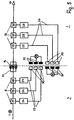
- Fig. 1 schematically shows the circuit configuration of the power supply part 3 and the device. 1
- Indicated at 5 are battery cells which are parts of the battery packs. These packs may have one or more primary cells or one or more secondary cells 5.
- a charge / discharge circuit 6 is accommodated in the housing 4. Such circuits are known and are therefore not explained in detail. With this circuit 6 is also a control and monitoring of the battery cells. 5
- housing 4 has batteries or battery packs, then various control or monitoring elements can also be accommodated in the housing 4.
- a battery circuit is shown, the positive pole 7 is separated over at least two, in the embodiment via three series-connected switch 8 of output terminals 9 of a positive output pole 10, which forms a supply contact.
- the switches 8 are advantageously transistors, in particular FETs. In the illustrated embodiment, three switches 8 are provided. The number of these switches 8 depends on which hazardous area zone or division the device 1 is to be used with the power supply part 3. When used in the zone 1, two switches 8 are sufficient, while three switches 8 are provided for use in the ex-zone zone. When used in Division 1 three Schlter are provided. This redundancy of the switch 8 ensures that in case of failure of the switch 8, the reliability remains ensured.
- the negative pole 11 of the circuit is connected to a negative output terminal 12 (supply contact), which is provided with corresponding output terminals 13.
- the power supply part 3 can be used in the Ex zones 0, 1, 2 or divisions 1, 2, the two output poles 10, 12 each have three output terminals 9, 13.
- the device 1 is provided with a corresponding positive input terminal 14 (supply contact) and a corresponding negative input terminal 15 (supply contact). Both input poles 14, 15 have a number of output terminals 9, 13 corresponding number of positive input terminals 16 and negative input terminals 17.
- the positive input terminal 14 of the device 1 is at least two, in the illustrated embodiment, three in series switches 18 connected to the positive terminal 19 and the negative input terminal 15 to the negative terminal 19.
- the switches 18 are advantageously transistors, in particular FETs.
- the number of switches 18 in turn depends on which zone or division the device is to be used.
- the redundancy of the switch 18 ensures that in case of failure of one of the switches, the reliability of the device is guaranteed in each Ex area.
- At least one signal line 21 is provided for communication between the power supply part 3 and the device 1 via at least one signal line 23 of the device is conductively connected.
- These signal lines 21, 23 are advantageously bidirectional communication lines.
- the switches 8 in the form of the transistors are each controlled by drive circuits 24, which are known per se.
- the switches 18 in the form of the transistors are each controlled by drive circuits 25 in a known manner.
- the drive circuits 24, 25 operate independently of each other and control one of the transistors 8, 18, respectively.
- the control signal 26 for the drive circuits 24 is generated in the device 1 and the control signal 27 for the drive circuits 25 in the power supply part 3.
- the shorting bar 28 may be incorporated depending on the design of the contacts in different positions, such as vertical, horizontal or oblique.
- contacts 29, which are advantageously flat and made of electrically conductive, for example, metallic material.
- the short-circuiting strip 28 has a basic body 31 made of electrically insulating material, which for example has a rectangular outline.
- the contacts 29 are fastened in a suitable manner on the base body 31 of the short-circuiting strip 28.
- the contacts 29 can be glued or plugged or screwed onto the base body 28, for example.
- Another possibility is to metallize the main body 31 to form the contacts 29 (plating) or to coat galvanically.
- the contacts 29 may have any suitable shape.
- the flat contacts 29 have a sloping contact side 32 which merges at one end into an arcuate end piece 33 which extends in the direction of the upper side of the main body 31.
- the contact side 32 passes approximately at right angles into a straight end piece 34, which extends to the main body.
- the flat contacts 29 extend for example perpendicular to the longitudinal direction of the shorting bar 28th
- the contacts 29 are advantageously identical to one another and are at a distance, advantageously at the same distance, next to each other ( 6 and 7 ).
- the main body 31 of the shorting bar 28 is provided with a top 35 which according to Fig. 6 has an exemplary rectangular outline, but is slightly smaller than the main body 31. Seen in plan view on the shorting bar 28 ( Fig. 6 ), Thus, the peripheral edge of the attachment 35 has a small distance from the peripheral edge of the body 31.
- the top of the attachment 35 extends obliquely, as in particular Fig. 8 shows.
- the removable form of the shorting bar 28 is not intended to be limiting. It may have any other suitable design and shape, depending on how the power supply part 3 and / or the device 1 are formed.
- the interacting with the contacts 29 contact elements 30 are located on a contact strip 36, as exemplified in the Fig. 9 to 11 is shown.
- the contact strip 36 has a main body 37, which consists of electrically insulating material, such as plastic, and in the mounting holes 37 'are provided. It has an example approximately rectangular shape and is provided with through holes 38 through which the contact elements 30 protrude. They are advantageously designed as spring contact pins. They protrude beyond the upper side 39 of the main body 37.
- the contact elements 30 have spherical contact surfaces 40, whereby a reliable contact with the contacts 29 is ensured.
- the other End of the contact elements 30 is located within a recess 41 in the bottom 42 of the body 37. Thus, the contact elements 30 are not on the bottom 42 of the body 37 before.
- the contact elements 30 are arranged by way of example in two rows at a distance next to and behind each other. This is only an exemplary distribution and arrangement of the contact elements 30. The respective position of the contact elements depends on the position of the contacts 29 of the short-circuiting strip 28.
- the contact elements 30 are secured in the through holes 38 in a suitable manner, for example glued or pressed.
- control lines 43, 44 ( Fig. 1 and 2 ), with which the control signals 26, 27 are supplied via the contacts 29 to the drive circuits 24, 25 ( Fig. 1 and 2 ).
- control lines 43, 44 are advantageously connectors 45, 46, so that when removing the power supply part 3 from the device 1, the signal connection to the drive circuits 24, 25 is interrupted.
- the connectors 45, 46 are located in the power supply part 3.
- the switches 8 are enabled by the device-side control signals 26 via the drive circuits 24.
- the switches 18 are enabled by the control signals 27 of the power supply part 3 via the drive circuits 25. This type of circuit ensures that without the control signal 26 of the device 1, the output pole 10 and without the control signal 27 of the power supply part 3 of the input 14 of the device 1 remains closed.
- the output terminals 9, 13 and the input terminals 16, 17 are each provided in triplicate and can be opposite to the connectors 22, 45, 46 or be designed nacheilend, so that they are not contacted simultaneously during installation or removal of the power supply part 3 or from each other. It is also possible, the output terminals 9, 13 and the input terminals 16, 17 perform opposite to each other or lagging.
- the control signals 26, 27 are supplied independently to the respective drive circuits 24, 25.
- the control lines 43, 44 are insulated from each other, so that the control signals 26, 27 can be fed undisturbed to the respective drive circuit 24, 25.
- the control signals 26, 27 have electrically different potential.
- the drive circuits 24, 25 may be discretely constructed from respective electrical / electronic components. But they can also be present as integrated circuits.
- the contacts 29 of the shorting bar 28 are also isolated from each other, so that there is no connection to other circuit parts of the device 1 and the power supply part 3.
- the supply of the control signals 26, 27 to the drive circuits 24, 25 takes place with the aid of the contact elements 30 of the contact strip 36.
- the control signals 26, 27 are supplied to the drive circuits 24, 25 in isolation from other signals.
- the power supply part 3 is located. If the power supply part 3 to the receiving compartment 2 are removed, is a multi-stage form of expression, based on the Fig. 12 to 15 is explained, ensures that the power supply part can only be removed when the supply contacts 10, 14; 12, 15 between the power supply part and the device 1 are energized or de-energized. As a result, no spark can occur when removing the power supply part 3.
- the supply of the control signals 26, 27 to the associated drive circuits 24, 25 may also be effected by switches or contact spring tongues, which are mounted on a bar or directly in / on the housing 4 of the power supply part 3 or in / on the housing of the device 1.
- Fig. 3 In the embodiment according to Fig. 3 are provided instead of the immediately coming into contact with each other contacts 29 and contact elements 30 magnets 47 and 48 magnetic sensors.
- the control signals 26, 27 are generated by magnetic excitation and supplied from the magnetic sensors 48 to the drive circuits 24, 25.
- the device 1 and the power supply part 3 are each provided with three magnets 47 and three magnetic sensors 48. If the power supply part 3 is inserted into the receptacle 2 of the device 1, the magnetic sensors 48 detect the respective magnets 47 and thereby generate the control signals 26, 27.
- the switches 8, 18 are enabled in the form of transistors via a mutual entanglement , so that in turn it is ensured that the supply contacts 10, 14; 12, 13 remain closed when the control signals 26, 27 are not triggered.
- the magnets 47 located in the power supply part 3 are detected by the corresponding, independently operating magnetic sensors 48 in the device 1.
- the independently operating magnetic sensors 48 in the power supply part 3 detect the corresponding magnets 47 in the device 1.
- the magnets 47 which are permanent magnets, and the magnetic sensors 48 work together without contact.
- the circuit of this embodiment is the same and operates in the same manner as in the previous embodiment.
- the control signals 26, 27 are generated inductively.
- the magnets 47 and proximity sensors 49 are provided.
- the device 1 and the power supply part 3 each have three permanent magnets 47 and three proximity sensors 49.
- the proximity sensors 49 are connected to a respective one of the drive circuits 24, 25.
- proximity sensors 49 that are energized upon the approach of metals, such as iron, may be used.
- the triggering elements 47 could be metal pieces or surfaces. When these metal pieces 47 approach the proximity sensors 49, the control signals 26, 27 are generated.
- the proximity sensors 49 of the energy supply part 3 approach the permanent magnet 47 of the device 1 and the permanent magnets 47 of the energy supply part 3 approach the proximity sensors 49 of the device 1.
- the proximity sensors 49 operate independently of each other.
- Fig. 5 shows an embodiment in which the control signals 26, 27 are capacitively generated.
- the device 1 and the power supply part 3 each have the proximity sensors 50 which generate the control signals 26, 27 and supply the drive circuits 24, 25 independently of each other.
- the device 1 and the power supply part 3 are also provided with capacitively exciting surfaces 51 which face the respective proximity sensors 50 when the power supply part 3 is inserted. As these surfaces 51 approach the proximity sensors 50, the control signals 26, 27 are generated. The potential 52 of the power supply part 3 provided capacitively exciting surfaces 51 is generated in the power supply part 3. The potential 53 of the capacitively exciting surfaces 51 in the device 1 is generated in the device.
- Fig. 12 shows the power supply part 3 in side view.
- the flat contacts 29 On the rear side 54 of the power supply part 3 are the flat contacts 29, which are arranged in series next to each other. If the power supply part 3 is inserted into the receiving compartment 2 of the device 1, the contacts 29 are in engagement with the device-side contact elements 30, which are provided on the contact strip 36. The contact elements 30 project beyond the rear side 54 of the power supply part 3 facing side wall 55 of the receiving compartment 2.
- the contacts 29 are located by way of example in half the width of the rear wall 54 (FIG. Fig. 12 ). On both sides of the contacts 29 54 slide guides 56, 57 are provided in the rear wall, which are advantageously formed as depressions in the rear wall 54.
- the two slotted guides 56, 57 are mirror-symmetrical to each other in the example given, in order to produce a reverse rotation of the opening movement.
- a pin 58, 59 which on sliders 60, 61 (FIG. Fig. 13 ) is provided.
- the slider 60, 61 are arranged on one side 62 of the device 1 adjacent to the receiving compartment 2.
- the slides 60, 61 are recessed in the side 62.
- the pins 58, 59 are from the sliders 60, 61 inwardly from that they protrude into the slotted guides 56, 57 of the power supply part 3.
- the pins 58, 59 are in an upper horizontal portion 63, 64 of the two Slotted guides 56, 57. In this position, the sliders 60, 61 are shifted so far toward each other that they have the smallest distance from each other.
- the two slides 60, 61 are opposite to each other in the direction of arrow 1 (FIG. FIGS. 12 and 13 ) postponed.
- the pins 58, 59 provided on the slides 60, 61 pass into a vertical section 65, 66 of the slide guides 56, 57.
- the slides 60, 61 can then no longer be displaced oppositely to one another.
- the power supply part 3 is then by means of a handle 67 in the direction of arrow 2 ( Fig. 14 ) raised.
- the slotted guides 56, 57 move relative to the located in the vertical sections 65, 66 pins 58, 59, until they reach a lower horizontal portion 68, 69 of the slotted guides. Then the energy supply part can no longer be raised ( Fig. 14 ).
- the lower horizontal portions 68, 69 then go into vertically downwardly extending end portions 70, 71, which are open to the bottom 72 of the power supply part 3. This makes it possible to completely remove the power supply part 3 from the receiving compartment 2.
- the power supply part 3 is overlapped on the opposite side by a tab 73. It ensures that the power supply part 3 can be removed from the receiving compartment 2 only by the described pivoting movement.
- the multistage shape mimic described ensures that the power supply part 3 can be removed from the receiving compartment 2 only after a multi-stage unlocking process. This ensures that initially the control signals 26, 27 generating circuit 29, 30; 47, 48; 47, 49; 50, 51 the supply contacts 10, 14; 12, 15 switched off. This happens in the embodiment of the Fig. 1 and 2 in that the contact elements 30 in the form of the spring contact pins are disengaged from the contacts 29. In the embodiments according to the Fig. 3 to 5 the magnets 47 and the capacitively exciting surfaces 51 are removed by the proximity sensors 49, 50. Only upon complete removal of the power supply part 3, the supply contacts 10, 14; 12, 15 separated from each other. Since they are now dead, no spark when removing the power supply part 3 can arise.
- the power supply part 3 does not have to be able to be inserted into a receiving compartment 2 in the manner described. It is also conceivable to use the power supply in a slot. In this case, the power supply part 3 is pushed into the device 1. Even then it can be ensured that when pulling out of the power supply part 3, first the supply contacts 10, 14; 12, 15 are de-energized before the power supply is completely pulled out.
- a multi-level form of expression can be provided in the side walls of the insertion compartment.
Landscapes
- Engineering & Computer Science (AREA)
- Chemical & Material Sciences (AREA)
- Chemical Kinetics & Catalysis (AREA)
- Electrochemistry (AREA)
- General Chemical & Material Sciences (AREA)
- Microelectronics & Electronic Packaging (AREA)
- Power Engineering (AREA)
- Manufacturing & Machinery (AREA)
- Portable Nailing Machines And Staplers (AREA)
- Details Of Connecting Devices For Male And Female Coupling (AREA)
- Charge And Discharge Circuits For Batteries Or The Like (AREA)
- Battery Mounting, Suspending (AREA)
Abstract
Das Gerät (1) zum Einsatz im Ex-Bereich hat ein Gerätegehäuse und wenigstens ein Energieversorgungsteil (3), das wenigstens eine Batterie (5) oder wenigstens einen Akku (5) sowie energieseitige Versorgungskontakte (10, 12) aufweist. Sie wirken mit geräteseitigen Versorgungskontakten (14, 15) zusammen, wenn das Energieversorgungsteil (3) an das Gerät (1) angeschlossen ist. Den Versorgungskontakten (10, 12; 14, 15) sind Schalter (8, 18) vorgeschaltet, die vor Trennung des Energieversorgungsteiles (3) vom Gerät (1) mittels einer Schaltung (29, 30) so ansteuerbar sind, dass sie die Versorgungskontakte (10, 12; 14, 15) spannungslos schalten.

Description
Die Erfindung betrifft ein Gerät zum Einsatz im Ex-Bereich nach dem Oberbegriff des Anspruches 1.The invention relates to a device for use in hazardous areas according to the preamble of
In Ex-Bereichen werden elektrische Geräte eingesetzt, die mit einem Energieversorgungsteil in Form wenigstens einer Batterie oder wenigstens eines Akkus ausgerüstet sind. Solche Geräte sind beispielsweise Messgeräte, Panels, Analysengeräte, mobile Computer und dergleichen. Ein Wechsel des Energieversorgungsteiles im Ex-Bereich ist nicht möglich, weil im Kontaktbereich zwischen den Versorgungskontakten, mit denen das Gerät und das Energieversorgungsteil oder -modul elektrisch miteinander verbunden sind, ein Zündfunke entstehen kann, der eine Zündung einer explosionsfähigen Atmosphäre im Ex-Bereich auslösen kann. Aus diesem Grunde müssen die Geräte für den Wechsel des Energieversorgungsteiles aus dem Ex-Bereich entfernt werden, um im sicheren Bereich den Wechsel des Energieversorgungsteiles durchzuführen.In hazardous areas, electrical appliances are used which are equipped with a power supply unit in the form of at least one battery or at least one battery. Such devices include, for example, gauges, panels, analyzers, mobile computers, and the like. It is not possible to change the power supply unit in the Ex area, because in the area of contact between the supply contacts, with which the device and the power supply unit or module are electrically connected to each other, a spark can occur which trigger ignition of a potentially explosive atmosphere in the Ex area can. For this reason, the devices for changing the power supply unit must be removed from the Ex area in order to carry out the change of the power supply unit in the safe area.
Der Erfindung liegt die Aufgabe zugrunde, das gattungsgemäße Gerät so auszubilden, dass ein Wechsel des Energieversorgungsteiles im Ex-Bereich möglich ist.The invention is based on the object, the generic device in such a way that a change of the power supply part in the Ex area is possible.
Diese Aufgabe wird beim gattungsgemäßen Gerät erfindungsgemäß mit den kennzeichnenden Merkmalen des Anspruches 1 gelöst.This object is achieved in the generic device according to the invention with the characterizing features of
Das erfindungsgemäße Gerät zeichnet sich dadurch aus, dass den Versorgungskontakten des Gerätes und des Energieversorgungsteiles jeweils Schalter vorgeschaltet sind, mit denen vor dem Entfernen des Energieversorgungsteiles vom Gerät die Versorgungskontakte spannungslos geschaltet werden. Hierfür ist die Schaltung vorgesehen, welche die Schalter so ansteuert, dass die Versorgungskontakte spannungslos sind. Wenn daher anschließend die Versorgungskontakte von Gerät und Energieversorgungsteiles voneinander gelöst werden, kann in Folge des spannungslosen Zustandes kein Zündfunke entstehen. Darum kann im Ex-Bereich ein Wechsel des Energieversorgungsteiles durchgeführt werden.The device according to the invention is characterized in that the supply contacts of the device and the power supply part each switch are connected upstream, with which the supply contacts are disconnected from power before removing the power supply part. For this purpose, the circuit is provided, which controls the switches so that the supply contacts are de-energized. If so then the supply contacts of the device and energy supply parts are disconnected from each other, no spark can arise as a result of the dead state. Therefore, a change of the energy supply part can be carried out in the Ex area.
Das erfindungsgemäße Gerät kann in allen definierten Ex-Bereichen (Zonen 0, 1, 2 sowie Divisions 1, 2) eingesetzt werden.The device according to the invention can be used in all defined Ex areas (
Vorteilhaft steuert die Schaltung die Schalter bei der Verbindung des Energieversorgungsteiles mit dem Gerät so an, dass die Versorgungskontakte erst dann Spannung haben können, wenn sie bereits zusammengesteckt sind.Advantageously, the circuit controls the switches in the connection of the power supply part with the device so that the supply contacts can only have voltage when they are already plugged together.
Eine einfache, zuverlässige und kostengünstige Lösung besteht darin, als Schalter Transistoren, insbesondere FETs, zu verwenden.A simple, reliable and inexpensive solution is to use as switches transistors, in particular FETs.
Das Gerät und das Energieversorgungsteil weisen vorteilhaft jeweils wenigstens zwei Schalter auf, die unabhängig voneinander angesteuert werden.Durch diese Redundanz der Schalter wird eine hohe Sicherheit gewährleistet. Wird das Gerät beispielsweise in der Zone 1 eingesetzt, dann reichen zwei Schalter für das Gerät sowie das Energieversorgungsteil aus. Ist ein Einsatz in der Zone 0 vorgesehen, dann sind für das Gerät und das Energieversorgungsteil drei unabhängig voneinander ansteuerbare Schalter vorgesehen.The device and the power supply part advantageously each have at least two switches, which are controlled independently of one another. This redundancy of the switches ensures a high degree of safety. If the device is used, for example, in
Die Schaltung ist vorteilhaft so ausgebildet, dass sie Steuersignale für Ansteuerschaltungen erzeugt, mit denen jeder einzelne Schalter unabhängig angesteuert werden kann.The circuit is advantageously designed so that it generates control signals for drive circuits, with which each individual switch can be controlled independently.
Damit die Versorgungskontakte, über welche das Gerät und das Energieversorgungsteil miteinander elektrisch verbunden sind, zuverlässig spannungslos geschaltet werden können, weist bei einer vorteilhaften Ausführungsform die Schaltung geräteseitige und energieseitige Schaltelemente auf. Die geräteseitigen Schaltelemente betätigen die energieseitigen Schalter und die energieseitigen Schaltelemente die geräteseitigen Schalter. Durch diese gegenseitige Verschränkung ist sichergestellt, dass das Energieversorgungsteil im Ex-Bereich ausgetauscht werden kann, ohne dass ein Zündfunke entsteht. Ohne das geräteseitig ausgelöste Signal bleibt der Versorgungskontakt des Energieversorgungsteiles geschlossen. Ohne das vom Energieversorgungsteil ausgelöste Signal bleibt umgekehrt der Versorgungskontakt des Gerätes geschlossen.So that the supply contacts, via which the device and the power supply part are electrically connected to one another, can be switched reliably de-energized, in an advantageous embodiment the circuit has device-side and energy-side switching elements on. The device-side switching elements actuate the power-side switches and the power-side switching elements the device-side switch. This mutual entanglement ensures that the energy supply part can be exchanged in the hazardous area without a spark being generated. Without the device-triggered signal, the supply contact of the power supply unit remains closed. Without the signal triggered by the power supply unit, the supply contact of the device remains closed.
Bei einer vorteilhaften Ausführungsform weist die Schaltung als Schaltelemente Flächenkontakte und mit ihnen zusammenwirkende Kontaktelemente auf, die vorzugsweise Federkontaktstifte sind. Beim Entfernen des Energieversorgungsteiles kommen zunächst die Kontaktelemente außer Eingriff mit den Flächenkontakten, wodurch die Versorgungskontakte, die noch miteinander verbunden sind, spannungslos gemacht werden.In an advantageous embodiment, the circuit as a switching elements surface contacts and cooperating with them contact elements, which are preferably spring contact pins. When removing the power supply part, first the contact elements come out of engagement with the surface contacts, whereby the supply contacts, which are still connected to each other, are de-energized.
Um einen einfachen Einbau der Flächenkontakte zu ermöglichen, ist es vorteilhaft, wenn die Flächenkontakte auf einer Kurzschlussleiste vorgesehen sind. Auf ihr können die Flächenkontakte in der erforderlichen Lage positioniert werden. Die Kurzschlussleiste lässt sich dann mit den vormontierten Flächenkontakten einfach einbauen.In order to enable a simple installation of the surface contacts, it is advantageous if the surface contacts are provided on a shorting bar. On it, the surface contacts can be positioned in the required position. The shorting bar can then be easily installed with the pre-assembled surface contacts.
Vorteilhaft sind die Kontaktelemente auf einer Kontaktleiste angeordnet. Auch sie kann vorab mit den Kontaktelementen bestückt und anschließend in einfacher Weise montiert werden.Advantageously, the contact elements are arranged on a contact strip. Also, it can be pre-populated with the contact elements and then mounted in a simple manner.
Die Schaltung kann als Schaltelemente auch Dauermagnete und Magnetsensoren aufweisen. Wird das Energieversorgungsteil vom Gerät gelöst, entfernen sich die Dauermagnete von den Magnetsensoren, wodurch die Schalter so angesteuert werden, dass sie die Versorgungskontakte zwischen dem Energieversorgungsteil und dem Gerät spannungslos schalten. Die Schaltung kann als Schaltelemente bei einer weiteren Ausführung Näherungssensoren und mit ihnen zusammenwirkende induktive oder kapazitive Elemente aufweisen. Wird das Energieversorgungsteil vom Gerät abgenommen, verlassen die induktiven oder kapazitiven Elemente den Erfassungsbereich der Näherungssensoren, die dann über die Schalter die Versorgungskontakte spannungslos machen.The circuit can also have permanent magnets and magnetic sensors as switching elements. When the power supply is released from the device, the permanent magnets move away from the magnetic sensors, causing the switches to be energized to de-energize the supply contacts between the power supply and the device. In a further embodiment, the circuit may have proximity sensors and inductive or capacitive elements cooperating with them as switching elements. When the power supply unit is removed from the device, the inductive or capacitive elements leave the detection range of the proximity sensors, which then de-energize the supply contacts via the switches.
Damit die Versorgungskontakte vor dem Lösen zuverlässig spannungslos gemacht werden können, ist das Gehäuse des Gerätes und/oder das Gehäuse des Energieversorgungsteiles mit wenigstens einer mehrstufigen Kulissenführung versehen, in die wenigstens ein Kulissenstein eingreift. Die Kulissenführung sorgt dafür, dass im Zusammenwirken mit dem Kulissenstein zunächst die Schaltung betätigt wird, welche die Versorgungskontakte, solange sie noch miteinander verbunden sind, spannungslos macht.So that the supply contacts can be reliably de-energized before loosening, the housing of the device and / or the housing of the power supply part is provided with at least one multi-stage link guide, in which engages at least one sliding block. The slotted guide ensures that in conjunction with the sliding block, the circuit is first actuated, which makes the supply contacts, as long as they are still connected to each other, de-energized.
Bei einer vorteilhaften Ausführungsform ist die Kulissenführung so ausgebildet, dass beim Entfernen des Energieversorgungsteiles vom Gerät in einer ersten Stufe zunächst über die Schaltung die Versorgungskontakte spannungslos geschaltet werden.In an advantageous embodiment, the slotted guide is designed so that when removing the power supply part of the device in a first stage, the power supply contacts are first switched off via the circuit.
In einer nachfolgenden Stufe werden dann erst die Versorgungskontakte von Gerät und Energieversorgungsteil voneinander gelöst.In a subsequent stage, the supply contacts of the device and the energy supply part are then only released from each other.
Der Anmeldungsgegenstand ergibt sich nicht nur aus dem Gegenstand der einzelnen Patentansprüche, sondern auch durch alle in den Zeichnungen und der Beschreibung offenbarten Angaben und Merkmale. Sie werden, auch wenn sie nicht Gegenstand der Ansprüche sind, als erfindungswesentlich beansprucht, soweit sie einzeln oder in Kombination gegenüber dem Stand der Technik neu sind.The subject of the application results not only from the subject matter of the individual claims, but also by all the information and features disclosed in the drawings and the description. They are, even if they are not the subject of the claims, claimed as essential to the invention, as far as they are new individually or in combination over the prior art.
Weitere Merkmale der Erfindung ergeben sich aus den weiteren Ansprüchen, der Beschreibung und den Zeichnungen.Further features of the invention will become apparent from the other claims, the description and the drawings.
Die Erfindung wird anhand einiger in den Zeichnungen dargestellter Ausführungsformen näher erläutert. Es zeigen
- Fig. 1
- in schematischer Darstellung den Schaltungsaufbau eines erfindungsgemäßen Gerätes mit einem Energieversorgungsteil,
- Fig. 2
- in vergrößerter Darstellung einen Teil des Schaltungsaufbaus gemäß
Fig. 1 , - Fig. 3
- in einer Darstellung entsprechend
Fig. 2 eine zweite Ausführungsform des Schaltungsaufbaus des erfindungsgemäßen Gerätes, - Fig. 4
- in einer Darstellung gemäß
Fig. 3 den Schaltungsaufbau einer weiteren Ausführungsform eines erfindungsgemäßen Gerätes, - Fig. 5
- in einer Darstellung entsprechend
Fig. 3 den Schaltungsaufbau einer weiteren Ausführungsform eines erfindungsgemäßen Gerätes, - Fig. 6
- eine Draufsicht auf eine Kurzschlussleiste des erfindungsgemäßen Gerätes,
- Fig. 7
- eine Vorderansicht der Kurzschlussleiste gemäß
Fig. 6 , - Fig. 8
- eine Seitenansicht der Kurzschlussleiste gemäß
Fig. 6 , - Fig. 9
- eine Draufsicht auf eine Kontaktstiftleiste des erfindungsgemäßen Gerätes,
- Fig. 10
- eine Seitenansicht der Kontaktstiftleiste gemäß
Fig. 9 , - Fig. 11
- eine Unteransicht der Kontaktstiftleiste gemäß
Fig. 9 , - Fig. 12
- die Kontaktseite des Energieversorgungsteiles des erfindungsgemäßen Gerätes,
- Fig. 13 bis Fig. 15
- jeweils in perspektivischer Darstellung den Entnahmevorgang des Energieversorgungsteiles aus dem erfindungsgemäßen Gerät.
- Fig. 1
- a schematic representation of the circuit configuration of a device according to the invention with a power supply part,
- Fig. 2
- in an enlarged view a part of the circuit structure according to
Fig. 1 . - Fig. 3
- in a representation accordingly
Fig. 2 A second embodiment of the circuit structure of the device according to the invention, - Fig. 4
- in a representation according to
Fig. 3 the circuit structure of another embodiment of a device according to the invention, - Fig. 5
- in a representation accordingly
Fig. 3 the circuit structure of another embodiment of a device according to the invention, - Fig. 6
- a plan view of a short-circuit strip of the device according to the invention,
- Fig. 7
- a front view of the shorting bar according to
Fig. 6 . - Fig. 8
- a side view of the shorting bar according to
Fig. 6 . - Fig. 9
- a plan view of a contact pin header of the device according to the invention,
- Fig. 10
- a side view of the contact pin according to
Fig. 9 . - Fig. 11
- a bottom view of the contact pin according to
Fig. 9 . - Fig. 12
- the contact side of the power supply part of the device according to the invention,
- FIGS. 13 to 15
- each in a perspective view of the removal process of the power supply part of the device according to the invention.
Mit dem Gerät ist es möglich, in explosionsgefährdeten Zonen (Ex-Bereich) das Energieversorgungsteil zu wechseln, ohne dass eine Zündgefahr durch den Wechsel oder während des Wechsels entsteht. Dadurch ist es möglich, die Betriebszeit des Gerätes nahezu beliebig zu verlängern.With the device, it is possible to change the power supply unit in potentially explosive atmospheres (Ex area) without the risk of ignition due to changing or during the changeover. This makes it possible to extend the operating time of the device almost arbitrarily.
In den
Mit 5 sind Batterie/Akkumulatorzellen angegeben, die Teile der Batterie/Akkumulatorpacks sind. Diese Packs können eine oder mehrere Primärzellen oder eine oder mehrere Sekundärzellen 5 aufweisen. Im Falle von wiederaufladbaren Akkus bzw. Akkupacks ist im Gehäuse 4 eine Lade/Entladeschaltung 6 untergebracht. Solche Schaltungen sind bekannt und werden darum auch nicht näher erläutert. Mit dieser Schaltung 6 erfolgt auch eine Steuerung sowie Überwachung der Akkumulatorzellen 5.Indicated at 5 are battery cells which are parts of the battery packs. These packs may have one or more primary cells or one or more
Weist das Gehäuse 4 Batterien bzw. Batteriepacks auf, können auch dann verschiedene Steuer- oder Überwachungselemente im Gehäuse 4 untergebracht sein.If the housing 4 has batteries or battery packs, then various control or monitoring elements can also be accommodated in the housing 4.
In
Der Minuspol 11 der Schaltung ist mit einem negativen Ausgangspol 12 (Versorgungskontakt) verbunden, der mit entsprechenden Ausgangsklemmen 13 versehen ist.The
Damit das Energieversorgungsteil 3 in den Ex-Zonen 0, 1, 2 bzw. Divisions 1, 2 eingesetzt werden kann, haben die beiden Ausgangspole 10, 12 jeweils drei Ausgangsklemmen 9, 13.So that the
Das Gerät 1 ist mit einem entsprechenden positiven Eingangspol 14 (Versorgungskontakt) sowie einem entsprechenden negativen Eingangspol 15 (Versorgungskontakt) versehen. Beide Eingangspole 14, 15 weisen eine der Zahl der Ausgangsklemmen 9, 13 entsprechende Zahl von positiven Eingangsklemmen 16 sowie negativen Eingangsklemmen 17 auf.The
Der positive Eingangspol 14 des Gerätes 1 ist über wenigstens zwei, im dargestellten Ausführungsbeispiel über drei in Reihe geschaltete Schalter 18 mit dem Pluspol 19 und der negative Eingangspol 15 mit dem Minuspol 19 verbunden.The
Die Schalter 18 sind vorteilhaft Transistoren, insbesondere FETs. Die Zahl der Schalter 18 ist wiederum davon abhängig, in welcher Ex-Zone oder Division das Gerät eingesetzt werden soll. Die Redundanz der Schalter 18 stellt sicher, dass bei einem Ausfall eines der Schalter die Funktionssicherheit des Gerätes im jeweiligen Ex-Bereich gewährleistet ist.The
Falls die Lade/Entladeschaltung 6 für die Akkus zur Versorgung verwendet wird oder die Batterieschaltung Steuer- und/oder Überwachungsdaten bereitstellt, wird zur Kommunikation zwischen dem Energieversorgungsteil 3 und dem Gerät 1 wenigstens eine Signalleitung 21 bereitgestellt, die über Verbinder 22 mit wenigstens einer Signalleitung 23 des Gerätes leitungsverbunden wird. Diese Signalleitungen 21, 23 sind vorteilhaft bidirektionale Kommunikationsleitungen.If the charging / discharging
Die Schalter 8 in Form der Transistoren werden jeweils durch Ansteuerschaltungen 24 gesteuert, die für sich bekannt sind. Auch die Schalter 18 in Form der Transistoren werden jeweils durch Ansteuerschaltungen 25 in bekannter Weise gesteuert. Die Ansteuerschaltungen 24, 25 arbeiten unabhängig voneinander und steuern jeweils einen der Transistoren 8, 18.The
Das Steuersignal 26 für die Ansteuerschaltungen 24 wird im Gerät 1 und das Steuersignal 27 für die Ansteuerschaltungen 25 im Energieversorgungsteil 3 erzeugt. Die elektronische Verbindung zwischen dem Gerät 1 und dem Energieversorgungsteil bezüglich der Steuersignale 26, 27 erfolgt über eine Kurzschlussleiste 28, die aus elektrisch isolierendem Material besteht und im Gerät 1 oder im Energieversorgungsteil 3 vorgesehen sein kann. Die Kurzschlussleiste 28 kann je nach Ausführung der Kontakte in unterschiedlichen Lagen eingebaut sein, beispielsweise vertikal, horizontal oder schräg.The
Auf der Kurzschlussleiste 28 befinden sich Kontakte 29, die vorteilhaft flächig ausgebildet sind und aus elektrisch leitendem, beispielsweise aus metallischem Material bestehen. Die Zuführung der Steuersignale 26, 27 zu den Ansteuerschaltungen 24, 25 erfolgt über Kontaktelemente 30, die vorteilhaft als Federkontaktstifte ausgebildet sind. Wird das Energieversorgungsteil 3 in das Gerät 1 eingelegt, kommen die Kontaktelemente 30 des Gerätes 1 oder des Energieversorgungsteiles 3 in Kontakt mit den Kontaktelementen 30, wodurch die elektrische Verbindung zwischen dem Gerät 1 und dem Energieversorgungsteil 3 bezüglich der Steuersignale 26, 27 hergestellt wird. Ist die Kurzschlussleiste 28 im Gerät 1 untergebracht, dann kommen die Kontaktelemente 30 des Energieversorgungsteiles 3 in Kontakt mit den Kontakten 29. Umgekehrt kommen die Kontaktelemente 30 des Gerätes 1 mit den Kontakten 29 in Kontakt, wenn die Kurzschlussleiste 28 im Energieversorgungsteil 3 untergebracht ist.On the shorting
Wie aus den
Eine weitere Möglichkeit besteht darin, den Grundkörper 31 zur Bildung der Kontakte 29 metallisch zu bedampfen (plating) oder galvanisch zu beschichten.Another possibility is to metallize the
Die Kontakte 29 können jede geeignete Form haben. Im dargestellten Ausführungsbeispiel haben die flächigen Kontakte 29 eine schräg verlaufende Kontaktseite 32, die an einem Ende in ein bogenförmiges Endstück 33 übergeht, das sich in Richtung auf die Oberseite des Grundkörpers 31 erstreckt. Am anderen Ende geht die Kontaktseite 32 etwa rechtwinklig in ein gerade verlaufendes Endstück 34 über, das sich bis zum Grundkörper erstreckt.The
Wie
Die Kontakte 29 sind vorteilhaft untereinander gleich ausgebildet und liegen mit Abstand, vorteilhaft mit gleichem Abstand, nebeneinander (
Die schräge Lage der Kontaktseite 32 ermöglicht eine zuverlässige Verbindung der Kontaktelemente 30 mit den Kontakten 29 beim Einsetzen des Energieversorgungsteiles 3 in das Gerät 1. Um diese vorteilhafte Schräglage der Kontaktseite 32 einfach zu erreichen, ist der Grundkörper 31 der Kurzschlussleiste 28 mit einem Aufsatz 35 versehen, der gemäß
Die den
Die mit den Kontakten 29 zusammenwirkenden Kontaktelemente 30 befinden sich auf einer Kontaktleiste 36, wie sie beispielhaft in den
Die Kontaktelemente 30 sind beispielhaft in zwei Reihen mit Abstand neben- und hintereinander angeordnet. Dies ist nur eine beispielhafte Verteilung und Anordnung der Kontaktelemente 30. Die jeweilige Position der Kontaktelemente hängt von der Position der Kontakte 29 der Kurzschlussleiste 28 ab.The
Die Kontaktelemente 30 sind in den Durchgangsöffnungen 38 in geeigneter Weise befestigt, beispielsweise eingeklebt oder eingepresst.The
An die in der Vertiefung 41 liegenden Enden der Kontaktelemente 30 sind Steuerleitungen 43, 44 (
In den Steuerleitungen 43, 44 befinden sich vorteilhaft Steckverbinder 45, 46, so dass beim Abnehmen des Energieversorgungsteiles 3 vom Gerät 1 die Signalverbindung zu den Ansteuerschaltungen 24, 25 unterbrochen wird. Die Steckverbinder 45, 46 befinden sich im Energieversorgungsteil 3.In the
Die Schalter 8 werden durch die geräteseitigen Steuersignale 26 über die Ansteuerschaltungen 24 freigeschaltet. Gleichzeitig werden die Schalter 18 durch die Steuersignale 27 des Energieversorgungsteiles 3 über die Ansteuerschaltungen 25 freigeschaltet. Durch diese Art der Schaltung wird erreicht, dass ohne das Steuersignal 26 des Gerätes 1 der Ausgangspol 10 und ohne das Steuersignal 27 des Energieversorgungsteiles 3 der Eingang 14 des Gerätes 1 geschlossen bleibt.The
Die Ausgangsklemmen 9, 13 und die Eingangsklemmen 16, 17 sind jeweils dreifach vorhanden und können gegenüber den Verbindern 22, 45, 46 vor- oder nacheilend ausgeführt sein, so dass sie beim Einbau oder Ausbau des Energieversorgungsteiles 3 nicht gleichzeitig kontaktiert bzw. voneinander gelöst werden. Auch ist es möglich, die Ausgangsklemmen 9, 13 und die Eingangsklemmen 16, 17 einander gegenüber vor- oder nacheilend auszuführen.The
Die Steuersignale 26, 27 werden unabhängig voneinander den jeweiligen Ansteuerschaltungen 24, 25 zugeführt. Die Steuerleitungen 43, 44 sind gegeneinander isoliert, so dass die Steuersignale 26, 27 ungestört der jeweiligen Ansteuerschaltung 24, 25 zugeführt werden können. Bei der Ausführungsform gemäß den
Die Kontakte 29 der Kurzschlussleiste 28 sind ebenfalls voneinander isoliert, so dass keine Verbindung zu anderen Schaltungsteilen des Gerätes 1 sowie des Energieversorgungsteiles 3 besteht. Die Zuführung der Steuersignale 26, 27 zu den Ansteuerschaltungen 24, 25 erfolgt mit Hilfe der Kontaktelemente 30 der Kontaktleiste 36. Beim Einlegen des Energieversorgungsteiles 3 in das Aufnahmefach 2 des Gerätes 1 gelangen die Kontaktelemente 30 in die dafür vorgesehene Position an den Kontakten 29. Da diese Kontakte 29 isoliert voneinander und von den anderen Kontaktstellen sind, werden die Steuersignale 26, 27 isoliert von anderen Signalen den Ansteuerschaltungen 24, 25 zugeführt.The
Über die Kontaktelemente 30 wird detektiert, ob sich im Aufnahmefach 2 das Energieversorgungsteil 3 befindet. Soll das Energieversorgungsteil 3 dem Aufnahmefach 2 entnommen werden, wird über eine mehrstufige Formmimik, die anhand der
Die Zuführung der Steuersignale 26, 27 zu den zugehörigen Ansteuerschaltungen 24, 25 kann auch durch Schalter oder Kontaktfederzungen erfolgen, die auf einer Leiste oder direkt im/am Gehäuse 4 des Energieversorgungsteiles 3 oder im/am Gehäuse des Gerätes 1 angebracht sind.The supply of the control signals 26, 27 to the associated
Bei der Ausführungsform gemäß
Die im Energieversorgungsteil 3 befindlichen Magnete 47 werden von den entsprechenden, unabhängig voneinander arbeitenden Magnetsensoren 48 im Gerät 1 detektiert. In gleicher Weise detektieren die unabhängig voneinander arbeitenden Magnetsensoren 48 im Energieversorgungsteil 3 die entsprechenden Magnete 47 im Gerät 1.The
Die Magnete 47, die Dauermagnete sind, und die Magnetsensoren 48 arbeiten berührungslos zusammen. Im übrigen ist die Schaltung dieses Ausführungsbeispieles gleich ausgebildet und arbeitet in gleicher Weise wie bei der vorigen Ausführungsform.The
Bei der Ausführungsform gemäß
Ebenfalls können Näherungssensoren 49 verwendet werden, die auf die Annäherung von Metallen erregt werden, beispielsweise Eisen. Dann könnten die auslösenden Elemente 47 Metallstücke oder -flächen sein. Bei Annäherung dieser Metallstücke 47 an die Näherungssensoren 49 werden die Steuersignale 26, 27 erzeugt.In the embodiment according to
Also,
Wird das Energieversorgungsteil 3 in das Aufnahmefach 2 des Gehäuses 1 eingesetzt, nähern sich die Näherungssensoren 49 des Energieversorgungsteiles 3 den Dauermagneten 47 des Gerätes 1 und die Dauermagnete 47 des Energieversorgungsteiles 3 den Näherungssensoren 49 des Gerätes 1. Mit jedem Näherungssensor 49 wird eine der Ansteuerschaltungen 24, 25 mit dem jeweiligen Steuersignal 26, 27 versorgt. Wie bei den vorigen Ausführungsformen arbeiten die Näherungssensoren 49 unabhängig voneinander.If the
Das Gerät 1 und das Energieversorgungsteil 3 sind außerdem mit kapazitiv erregenden Flächen 51 versehen, die bei eingesetztem Energieversorgungsteil 3 den jeweiligen Näherungssensoren 50 gegenüberliegen. Bei Annäherung dieser Flächen 51 an die Näherungssensoren 50 werden die Steuersignale 26, 27 erzeugt. Das Potential 52 der im Energieversorgungsteil 3 vorgesehenen kapazitiv erregenden Flächen 51 wird im Energieversorgungsteil 3 erzeugt. Das Potential 53 der kapazitiv erregenden Flächen 51 im Gerät 1 wird im Gerät erzeugt.The
Im Übrigen ist die Ausführungsform gemäß
Die Kontakte 29 befinden sich beispielhaft in halber Breite der Rückwand 54 (
In die Kulissenführungen 56, 57 greift jeweils ein Stift 58, 59 ein, der an Schiebern 60, 61 (
Wenn das Energieversorgungsteil 3 in das Aufnahmefach 2 eingesetzt ist, liegen die Stifte 58, 59 in einem oberen Horizontalabschnitt 63, 64 der beiden Kulissenführungen 56, 57. In dieser Lage sind die Schieber 60, 61 so weit in Richtung zueinander verschoben, dass sie den geringsten Abstand voneinander haben.When the
Soll das Energieversorgungsteil 3 dem Aufnahmefach 2 entnommen werden, werden die beiden Schieber 60, 61 entgegengesetzt zueinander in Richtung des Pfeiles 1 (
In dieser angehobenen Stellung des Energieversorgungsteiles 3 lassen sich die beiden Schieber 60, 61 entgegengesetzt zueinander in Richtung des Pfeiles 3 (
Die unteren horizontalen Abschnitte 68, 69 gehen dann in vertikal nach unten verlaufende Endabschnitte 70, 71 über, die zur Unterseite 72 des Energieversorgungsteiles 3 offen sind. Dadurch ist es möglich, das Energieversorgungsteil 3 vollständig dem Aufnahmefach 2 zu entnehmen.The lower
Während des Entnahmevorganges wird das Energieversorgungsteil 3 an der gegenüberliegenden Seite von einer Lasche 73 übergriffen. Sie sorgt dafür, dass das Energieversorgungsteil 3 lediglich durch die beschriebene Schwenkbewegung dem Aufnahmefach 2 entnommen werden kann.During the removal process, the
Die beschriebene mehrstufige Formmimik sorgt dafür, dass das Energieversorgungsteil 3 nur nach einem mehrstufigen Entriegelungsprozess dem Aufnahmefach 2 entnommen werden kann. Dadurch wird erreicht, dass zunächst die die Steuersignale 26, 27 erzeugende Schaltung 29, 30; 47, 48; 47, 49; 50, 51 die Versorgungskontakte 10, 14; 12, 15 spannungslos schaltet. Dies geschieht bei der Ausführungsform nach den
Die beschriebene mehrstufige Formmimik ist nur beispielhaft zu verstehen. Beim Entfernen des Energieversorgungsteiles 3 ist lediglich dafür zu sorgen, dass die Versorgungskontakte 10, 14; 12, 15 zunächst spannungslos geschaltet werden, bevor die Versorgungskontakte voneinander gelöst werden.The multi-level form of expression described is only to be understood as an example. When removing the
Das Energieversorgungsteil 3 muss nicht in ein Aufnahmefach 2 in der beschriebenen Weise einlegbar sein. Vorstellbar ist es auch, das Energieversorgungsteil in ein Einschubfach einzusetzen. In diesem Falle wird das Energieversorgungsteil 3 in das Gerät 1 geschoben. Auch dann kann dafür gesorgt werden, dass beim Herausziehen des Energieversorgungsteiles 3 zunächst die Versorgungskontakte 10, 14; 12, 15 spannungslos geschaltet werden, bevor das Energieversorgungsteil vollständig herausgezogen wird. Hierfür kann beispielhaft auch eine mehrstufige Formmimik in den Seitenwänden des Einschubfaches vorgesehen sein.The
Claims (14)
dadurch gekennzeichnet, dass die Schaltung (29, 30; 47, 48; 47, 49; 50, 51) die Schalter (8, 18) bei der Verbindung des Energieversorgungsteiles (3) mit dem Gerät (1) so ansteuert, dass die Versorgungskontakte (10, 14; 12, 15) dann Spannung haben, wenn sie zusammengesteckt sind.Apparatus according to claim 1,
characterized in that the circuit (29, 30; 47, 48; 47, 49; 50, 51) activates the switches (8, 18) in connection with the power supply part (3) with the device (1) such that the supply contacts (10, 14; 12, 15) then have tension when put together.
dadurch gekennzeichnet, dass die Schalter (8, 18) Transistoren sind.Apparatus according to claim 1 or 2,
characterized in that the switches (8, 18) are transistors.
dadurch gekennzeichnet, dass das Gerät (1) und das Energieversorgungsteil (3) jeweils wenigstens zwei Schalter (8, 18) aufweist, die unabhängig voneinander ansteuerbar sind.Device according to one of claims 1 to 3,
characterized in that the device (1) and the power supply part (3) each have at least two switches (8, 18) which are independently controllable.
dadurch gekennzeichnet, dass die Schaltung (29, 30; 47, 48; 47, 49; 50, 51) Steuersignale (26, 27) für Ansteuerschaltungen (24, 25) erzeugt, mit denen jeder Schalter (8, 18) einzeln ansteuerbar ist.Device according to one of claims 1 to 4,
characterized in that the circuit (29, 30, 47, 48, 47, 49, 50, 51) generates control signals (26, 27) for drive circuits (24, 25) with which each switch (8, 18) can be controlled individually ,
dadurch gekennzeichnet, dass die Schaltung (29, 30; 47, 48; 47, 49; 50, 51) geräteseitige Schaltelemente (30; 47, 48; 47, 49; 50, 51) und energieseitige Schaltelemente (29; 47, 48; 47, 49; 50, 51) aufweist, von denen die geräteseitigen Schaltelemente die energieseitigen Schalter (8) und die energieseitigen Schaltelemente die geräteseitigen Schalter (18) betätigen.Device according to one of claims 1 to 5,
characterized in that the circuit (29, 30, 47, 48, 47, 49, 50, 51) device-side switching elements (30, 47, 48, 47, 49, 50, 51) and energy-side switching elements (29, 47, 48; 47, 49, 50, 51), of which the device-side switching elements the energy-side switch (8) and the power-side switching elements actuate the device-side switch (18).
dadurch gekennzeichnet, dass die Schaltung (29, 30) als Schaltelemente Flächenkontakte (29) und mit ihnen zusammenwirkende Kontaktelemente (30), vorzugsweise Federkontaktstifte, aufweist.Device according to one of claims 1 to 6,
characterized in that the circuit (29, 30) as switching elements surface contacts (29) and cooperating with them contact elements (30), preferably spring contact pins having.
dadurch gekennzeichnet, dass die Flächenkontakte (29) auf einer Kurzschlussleiste (36) vorgesehen sind.Apparatus according to claim 7,
characterized in that the surface contacts (29) on a shorting bar (36) are provided.
dadurch gekennzeichnet, dass die Kontaktelemente (30) auf einer Kontaktleiste (36) vorgesehen sind.Apparatus according to claim 7 or 8,
characterized in that the contact elements (30) are provided on a contact strip (36).
dadurch gekennzeichnet, dass die Schaltung (47, 48) als Schaltelemente Dauermagnete (47) und Magnetsensoren (48) aufweist.Device according to one of claims 1 to 6,
characterized in that the circuit (47, 48) as switching elements permanent magnets (47) and magnetic sensors (48).
dadurch gekennzeichnet, dass die Schaltung (47, 49; 50, 51) als Schaltelemente Näherungssensoren (49, 50) und mit ihnen zusammenwirkende induktive oder kapazitive Elemente (47, 51) aufweist.Device according to one of claims 1 to 6,
characterized in that the circuit (47, 49, 50, 51) as proximity elements proximity sensors (49, 50) and cooperating with them inductive or capacitive elements (47, 51).
dadurch gekennzeichnet, dass das Gehäuse des Gerätes (1) und/oder ein Gehäuse (4) des Energieversorgungsteiles (3) mit wenigstens einer mehrstufigen Kulissenführung (56, 57) versehen ist, in die wenigstens ein Kulissenstein (58, 59) eingreift.Device according to one of claims 1 to 11,
characterized in that the housing of the device (1) and / or a housing (4) of the power supply part (3) with at least one multi-stage link guide (56, 57) is provided in the at least one sliding block (58, 59) engages.
dadurch gekennzeichnet, dass die Kulissenführung ((56, 57) so ausgebildet ist, dass beim Entfernen des Energieversorgungsteiles (3) vom Gerät (1) in einer ersten Stufe zunächst über die Schaltung (29, 30; 47, 48; 47, 49; 50, 51) die Versorgungskontakte (10, 14; 12, 15) spannungslos geschaltet werden.Apparatus according to claim 12,
characterized in that the slotted guide ((56, 57) is formed so that when removing the power supply part (3) from the device (1) in a first stage first via the circuit (29, 30; 47, 48; 47, 49; 50, 51), the supply contacts (10, 14, 12, 15) are de-energized.
dadurch gekennzeichnet, das in einer nachfolgenden Stufe die Versorgungskontakte (10, 14; 12, 15) von Gerät (1) und Energieversorgungsteile (3) voneinander gelöst werden.Apparatus according to claim 12 or 13,
characterized in that in a subsequent stage the supply contacts (10, 14; 12, 15) of device (1) and power supply parts (3) are detached from each other.
Applications Claiming Priority (1)
| Application Number | Priority Date | Filing Date | Title |
|---|---|---|---|
| DE102017010107.8A DE102017010107A1 (en) | 2017-10-26 | 2017-10-26 | Device for use in hazardous areas |
Publications (3)
| Publication Number | Publication Date |
|---|---|
| EP3477790A2 true EP3477790A2 (en) | 2019-05-01 |
| EP3477790A3 EP3477790A3 (en) | 2019-07-24 |
| EP3477790B1 EP3477790B1 (en) | 2023-10-04 |
Family
ID=63878303
Family Applications (1)
| Application Number | Title | Priority Date | Filing Date |
|---|---|---|---|
| EP18000811.2A Active EP3477790B1 (en) | 2017-10-26 | 2018-10-15 | Device for use in the ex area |
Country Status (6)
| Country | Link |
|---|---|
| US (1) | US10897108B2 (en) |
| EP (1) | EP3477790B1 (en) |
| AU (1) | AU2018250434B2 (en) |
| DE (1) | DE102017010107A1 (en) |
| TW (1) | TWI710191B (en) |
| ZA (1) | ZA201806187B (en) |
Family Cites Families (12)
| Publication number | Priority date | Publication date | Assignee | Title |
|---|---|---|---|---|
| DE2740160A1 (en) * | 1977-09-02 | 1979-03-08 | Auergesellschaft Gmbh | POWER SUPPLY FOR MEASURING DEVICES |
| DE19748553A1 (en) * | 1997-11-04 | 1999-05-20 | Aeg Starkstrom Anlagenbau Magd | Push-in module for electrical switching gear |
| DE19838492A1 (en) * | 1998-08-25 | 2000-03-09 | Stahl R Schaltgeraete Gmbh | Explosion-proof connector assembly |
| DE10049346A1 (en) * | 1999-10-08 | 2001-04-12 | Tyco Electronics Amp Gmbh | Plug arrangement with swingable lid, has link guides on side wall of lower connector housing to reduce plug-in force of upper connector housing, when connecting it to lower housing by closing the lid |
| US7550943B2 (en) * | 2006-09-19 | 2009-06-23 | Eveready Battery Company, Inc. | Intrinsically safe battery-powered device |
| DE102006047039A1 (en) * | 2006-10-02 | 2007-11-08 | Leoni Bordnetz-Systeme Gmbh | Contact connection for motor vehicle`s electrical drive motor, has safety device with sensor system for detecting closed contact position of contact parts, where system has sensor and magnet that are galvanically separated from each other |
| TW200937788A (en) * | 2008-02-29 | 2009-09-01 | Chaun-Yuan Chen | An overheat safety protection of power supply socket when overloaded |
| TW201004098A (en) * | 2008-07-14 | 2010-01-16 | Lite On Technology Corp | Energy storage device, access device, and a combination thereof |
| US8094426B2 (en) * | 2009-06-02 | 2012-01-10 | Eaton Corporation | Electrical switching apparatus providing coordinated opening with a circuit interrupter and method of operating the same |
| DE102013213042B4 (en) * | 2013-07-04 | 2022-05-25 | Ecom Instruments Gmbh | Electronic circuit arrangement for use in a potentially explosive atmosphere |
| DE102013219950B4 (en) * | 2013-10-01 | 2018-12-13 | Ecom Instruments Gmbh | Electronic circuitry |
| JP6660696B2 (en) * | 2015-09-17 | 2020-03-11 | 三菱重工業株式会社 | Explosion-proof equipment |
-
2017
- 2017-10-26 DE DE102017010107.8A patent/DE102017010107A1/en not_active Withdrawn
-
2018
- 2018-09-14 ZA ZA2018/06187A patent/ZA201806187B/en unknown
- 2018-09-19 TW TW107132992A patent/TWI710191B/en not_active IP Right Cessation
- 2018-10-15 EP EP18000811.2A patent/EP3477790B1/en active Active
- 2018-10-18 AU AU2018250434A patent/AU2018250434B2/en active Active
- 2018-10-19 US US16/165,218 patent/US10897108B2/en active Active
Non-Patent Citations (1)
| Title |
|---|
| None |
Also Published As
| Publication number | Publication date |
|---|---|
| EP3477790A3 (en) | 2019-07-24 |
| US10897108B2 (en) | 2021-01-19 |
| ZA201806187B (en) | 2022-03-30 |
| AU2018250434A1 (en) | 2019-05-16 |
| AU2018250434B2 (en) | 2021-09-30 |
| EP3477790B1 (en) | 2023-10-04 |
| TWI710191B (en) | 2020-11-11 |
| DE102017010107A1 (en) | 2019-05-16 |
| TW201924171A (en) | 2019-06-16 |
| US20190131750A1 (en) | 2019-05-02 |
Similar Documents
| Publication | Publication Date | Title |
|---|---|---|
| EP2909059B1 (en) | Charging device for charging a electric vehicle at a charging station | |
| DE102004054360B4 (en) | Electrical connector coupling with switching function | |
| EP1794463B1 (en) | Device for locking electric appliances in particular electric tools with battery packs for power supply | |
| DE602006000986T2 (en) | Memory card socket structure | |
| DE1048189B (en) | Electric shaver | |
| DE2730660A1 (en) | ELECTRIC COUPLING DEVICE | |
| DE3423865A1 (en) | HOUSING OR RECEIVING DEVICE FOR PRINTED CIRCUIT BOARDS AND METHOD FOR AVOIDING SHARP PULSES IN THE SIGNAL APPLIED TO THE PRINTED CIRCUIT BOARD | |
| EP2715871B1 (en) | Test and connection apparatus arrangement | |
| WO2008135183A1 (en) | Device for checking the attachment of a circuit board on a carrier | |
| EP2656472A1 (en) | Field device having a battery unit | |
| DE69834450T2 (en) | television camera | |
| DE10003267C2 (en) | Circuit breaker device | |
| EP3032694B1 (en) | Battery pack with switchable total capacity | |
| DE2515918A1 (en) | MEANS OF INSTALLATION AND PROTECTION OF CIRCUITS | |
| EP1131987A1 (en) | Modular system for electrical printed-circuit boards with centering contacts on front elements and separate locating contacts, notably with contact blades in the rack assembly | |
| DE69508055T2 (en) | APPARATUS WITH TRANSIENT VOLTAGE SUPPRESSION | |
| EP3477790B1 (en) | Device for use in the ex area | |
| DE2046430B2 (en) | Test arrangement | |
| DE4407083A1 (en) | Connecting plug | |
| DE10040893A1 (en) | Terminal structure for battery pack, includes alterable number of elastic board formed on receptacle in entry direction of male terminal, for fitting male terminal | |
| DE3343270A1 (en) | Switchable single-phase AC voltage plug socket | |
| DE10066273B4 (en) | Terminal structure for battery pack, includes alterable number of elastic board formed on receptacle in entry direction of male terminal, for fitting male terminal | |
| EP3214415B1 (en) | Sensor comprising a microprocessor and method for providing and feeding a sensor signal into an installation bus of a building automation device | |
| DE202016107303U1 (en) | Battery terminal, battery terminal assembly and battery holder for a handheld transmitter for building or enclosure termination systems | |
| EP3131373A1 (en) | Circuit on circuit boards in a plurality of levels with interface for a plug-in card |
Legal Events
| Date | Code | Title | Description |
|---|---|---|---|
| PUAI | Public reference made under article 153(3) epc to a published international application that has entered the european phase |
Free format text: ORIGINAL CODE: 0009012 |
|
| STAA | Information on the status of an ep patent application or granted ep patent |
Free format text: STATUS: THE APPLICATION HAS BEEN PUBLISHED |
|
| AK | Designated contracting states |
Kind code of ref document: A2 Designated state(s): AL AT BE BG CH CY CZ DE DK EE ES FI FR GB GR HR HU IE IS IT LI LT LU LV MC MK MT NL NO PL PT RO RS SE SI SK SM TR |
|
| AX | Request for extension of the european patent |
Extension state: BA ME |
|
| PUAL | Search report despatched |
Free format text: ORIGINAL CODE: 0009013 |
|
| AK | Designated contracting states |
Kind code of ref document: A3 Designated state(s): AL AT BE BG CH CY CZ DE DK EE ES FI FR GB GR HR HU IE IS IT LI LT LU LV MC MK MT NL NO PL PT RO RS SE SI SK SM TR |
|
| AX | Request for extension of the european patent |
Extension state: BA ME |
|
| RIC1 | Information provided on ipc code assigned before grant |
Ipc: H03K 17/10 20060101ALI20190620BHEP Ipc: H01R 13/703 20060101AFI20190620BHEP |
|
| STAA | Information on the status of an ep patent application or granted ep patent |
Free format text: STATUS: REQUEST FOR EXAMINATION WAS MADE |
|
| 17P | Request for examination filed |
Effective date: 20200120 |
|
| RBV | Designated contracting states (corrected) |
Designated state(s): AL AT BE BG CH CY CZ DE DK EE ES FI FR GB GR HR HU IE IS IT LI LT LU LV MC MK MT NL NO PL PT RO RS SE SI SK SM TR |
|
| REG | Reference to a national code |
Ref document number: 502018013353 Country of ref document: DE Ref country code: DE Ref legal event code: R079 Free format text: PREVIOUS MAIN CLASS: H01R0013703000 Ipc: H03K0017100000 |
|
| GRAP | Despatch of communication of intention to grant a patent |
Free format text: ORIGINAL CODE: EPIDOSNIGR1 |
|
| STAA | Information on the status of an ep patent application or granted ep patent |
Free format text: STATUS: GRANT OF PATENT IS INTENDED |
|
| RIC1 | Information provided on ipc code assigned before grant |
Ipc: H01M 50/574 20210101ALI20230316BHEP Ipc: H01R 13/703 20060101ALI20230316BHEP Ipc: H03K 17/10 20060101AFI20230316BHEP |
|
| INTG | Intention to grant announced |
Effective date: 20230417 |
|
| GRAS | Grant fee paid |
Free format text: ORIGINAL CODE: EPIDOSNIGR3 |
|
| GRAA | (expected) grant |
Free format text: ORIGINAL CODE: 0009210 |
|
| STAA | Information on the status of an ep patent application or granted ep patent |
Free format text: STATUS: THE PATENT HAS BEEN GRANTED |
|
| AK | Designated contracting states |
Kind code of ref document: B1 Designated state(s): AL AT BE BG CH CY CZ DE DK EE ES FI FR GB GR HR HU IE IS IT LI LT LU LV MC MK MT NL NO PL PT RO RS SE SI SK SM TR |
|
| REG | Reference to a national code |
Ref country code: GB Ref legal event code: FG4D Free format text: NOT ENGLISH |
|
| REG | Reference to a national code |
Ref country code: CH Ref legal event code: EP |
|
| REG | Reference to a national code |
Ref country code: IE Ref legal event code: FG4D Free format text: LANGUAGE OF EP DOCUMENT: GERMAN |
|
| REG | Reference to a national code |
Ref country code: DE Ref legal event code: R096 Ref document number: 502018013353 Country of ref document: DE |
|
| REG | Reference to a national code |
Ref country code: LT Ref legal event code: MG9D |
|
| PGFP | Annual fee paid to national office [announced via postgrant information from national office to epo] |
Ref country code: FR Payment date: 20231114 Year of fee payment: 6 Ref country code: DE Payment date: 20231229 Year of fee payment: 6 |
|
| REG | Reference to a national code |
Ref country code: NL Ref legal event code: MP Effective date: 20231004 |
|
| PG25 | Lapsed in a contracting state [announced via postgrant information from national office to epo] |
Ref country code: NL Free format text: LAPSE BECAUSE OF FAILURE TO SUBMIT A TRANSLATION OF THE DESCRIPTION OR TO PAY THE FEE WITHIN THE PRESCRIBED TIME-LIMIT Effective date: 20231004 |
|
| PG25 | Lapsed in a contracting state [announced via postgrant information from national office to epo] |
Ref country code: GR Free format text: LAPSE BECAUSE OF FAILURE TO SUBMIT A TRANSLATION OF THE DESCRIPTION OR TO PAY THE FEE WITHIN THE PRESCRIBED TIME-LIMIT Effective date: 20240105 |
|
| PG25 | Lapsed in a contracting state [announced via postgrant information from national office to epo] |
Ref country code: IS Free format text: LAPSE BECAUSE OF FAILURE TO SUBMIT A TRANSLATION OF THE DESCRIPTION OR TO PAY THE FEE WITHIN THE PRESCRIBED TIME-LIMIT Effective date: 20240204 |
|
| PG25 | Lapsed in a contracting state [announced via postgrant information from national office to epo] |
Ref country code: LT Free format text: LAPSE BECAUSE OF FAILURE TO SUBMIT A TRANSLATION OF THE DESCRIPTION OR TO PAY THE FEE WITHIN THE PRESCRIBED TIME-LIMIT Effective date: 20231004 |
|
| PG25 | Lapsed in a contracting state [announced via postgrant information from national office to epo] |
Ref country code: ES Free format text: LAPSE BECAUSE OF FAILURE TO SUBMIT A TRANSLATION OF THE DESCRIPTION OR TO PAY THE FEE WITHIN THE PRESCRIBED TIME-LIMIT Effective date: 20231004 |
|
| PG25 | Lapsed in a contracting state [announced via postgrant information from national office to epo] |
Ref country code: LT Free format text: LAPSE BECAUSE OF FAILURE TO SUBMIT A TRANSLATION OF THE DESCRIPTION OR TO PAY THE FEE WITHIN THE PRESCRIBED TIME-LIMIT Effective date: 20231004 Ref country code: IS Free format text: LAPSE BECAUSE OF FAILURE TO SUBMIT A TRANSLATION OF THE DESCRIPTION OR TO PAY THE FEE WITHIN THE PRESCRIBED TIME-LIMIT Effective date: 20240204 Ref country code: GR Free format text: LAPSE BECAUSE OF FAILURE TO SUBMIT A TRANSLATION OF THE DESCRIPTION OR TO PAY THE FEE WITHIN THE PRESCRIBED TIME-LIMIT Effective date: 20240105 Ref country code: ES Free format text: LAPSE BECAUSE OF FAILURE TO SUBMIT A TRANSLATION OF THE DESCRIPTION OR TO PAY THE FEE WITHIN THE PRESCRIBED TIME-LIMIT Effective date: 20231004 Ref country code: BG Free format text: LAPSE BECAUSE OF FAILURE TO SUBMIT A TRANSLATION OF THE DESCRIPTION OR TO PAY THE FEE WITHIN THE PRESCRIBED TIME-LIMIT Effective date: 20240104 Ref country code: PT Free format text: LAPSE BECAUSE OF FAILURE TO SUBMIT A TRANSLATION OF THE DESCRIPTION OR TO PAY THE FEE WITHIN THE PRESCRIBED TIME-LIMIT Effective date: 20240205 |
|
| PG25 | Lapsed in a contracting state [announced via postgrant information from national office to epo] |
Ref country code: SE Free format text: LAPSE BECAUSE OF FAILURE TO SUBMIT A TRANSLATION OF THE DESCRIPTION OR TO PAY THE FEE WITHIN THE PRESCRIBED TIME-LIMIT Effective date: 20231004 Ref country code: RS Free format text: LAPSE BECAUSE OF FAILURE TO SUBMIT A TRANSLATION OF THE DESCRIPTION OR TO PAY THE FEE WITHIN THE PRESCRIBED TIME-LIMIT Effective date: 20231004 Ref country code: PL Free format text: LAPSE BECAUSE OF FAILURE TO SUBMIT A TRANSLATION OF THE DESCRIPTION OR TO PAY THE FEE WITHIN THE PRESCRIBED TIME-LIMIT Effective date: 20231004 Ref country code: NO Free format text: LAPSE BECAUSE OF FAILURE TO SUBMIT A TRANSLATION OF THE DESCRIPTION OR TO PAY THE FEE WITHIN THE PRESCRIBED TIME-LIMIT Effective date: 20240104 Ref country code: LV Free format text: LAPSE BECAUSE OF FAILURE TO SUBMIT A TRANSLATION OF THE DESCRIPTION OR TO PAY THE FEE WITHIN THE PRESCRIBED TIME-LIMIT Effective date: 20231004 Ref country code: HR Free format text: LAPSE BECAUSE OF FAILURE TO SUBMIT A TRANSLATION OF THE DESCRIPTION OR TO PAY THE FEE WITHIN THE PRESCRIBED TIME-LIMIT Effective date: 20231004 |
|
| REG | Reference to a national code |
Ref country code: CH Ref legal event code: PL |
|
| REG | Reference to a national code |
Ref country code: BE Ref legal event code: MM Effective date: 20231031 |
|
| PG25 | Lapsed in a contracting state [announced via postgrant information from national office to epo] |
Ref country code: LU Free format text: LAPSE BECAUSE OF NON-PAYMENT OF DUE FEES Effective date: 20231015 |
|
| PG25 | Lapsed in a contracting state [announced via postgrant information from national office to epo] |
Ref country code: LU Free format text: LAPSE BECAUSE OF NON-PAYMENT OF DUE FEES Effective date: 20231015 |
|
| REG | Reference to a national code |
Ref country code: DE Ref legal event code: R097 Ref document number: 502018013353 Country of ref document: DE |
|
| PG25 | Lapsed in a contracting state [announced via postgrant information from national office to epo] |
Ref country code: DK Free format text: LAPSE BECAUSE OF FAILURE TO SUBMIT A TRANSLATION OF THE DESCRIPTION OR TO PAY THE FEE WITHIN THE PRESCRIBED TIME-LIMIT Effective date: 20231004 |
|
| PG25 | Lapsed in a contracting state [announced via postgrant information from national office to epo] |
Ref country code: CH Free format text: LAPSE BECAUSE OF NON-PAYMENT OF DUE FEES Effective date: 20231031 |
|
| PG25 | Lapsed in a contracting state [announced via postgrant information from national office to epo] |
Ref country code: CZ Free format text: LAPSE BECAUSE OF FAILURE TO SUBMIT A TRANSLATION OF THE DESCRIPTION OR TO PAY THE FEE WITHIN THE PRESCRIBED TIME-LIMIT Effective date: 20231004 |
|
| PG25 | Lapsed in a contracting state [announced via postgrant information from national office to epo] |
Ref country code: SK Free format text: LAPSE BECAUSE OF FAILURE TO SUBMIT A TRANSLATION OF THE DESCRIPTION OR TO PAY THE FEE WITHIN THE PRESCRIBED TIME-LIMIT Effective date: 20231004 |
|
| PG25 | Lapsed in a contracting state [announced via postgrant information from national office to epo] |
Ref country code: SM Free format text: LAPSE BECAUSE OF FAILURE TO SUBMIT A TRANSLATION OF THE DESCRIPTION OR TO PAY THE FEE WITHIN THE PRESCRIBED TIME-LIMIT Effective date: 20231004 Ref country code: SK Free format text: LAPSE BECAUSE OF FAILURE TO SUBMIT A TRANSLATION OF THE DESCRIPTION OR TO PAY THE FEE WITHIN THE PRESCRIBED TIME-LIMIT Effective date: 20231004 Ref country code: RO Free format text: LAPSE BECAUSE OF FAILURE TO SUBMIT A TRANSLATION OF THE DESCRIPTION OR TO PAY THE FEE WITHIN THE PRESCRIBED TIME-LIMIT Effective date: 20231004 Ref country code: IT Free format text: LAPSE BECAUSE OF FAILURE TO SUBMIT A TRANSLATION OF THE DESCRIPTION OR TO PAY THE FEE WITHIN THE PRESCRIBED TIME-LIMIT Effective date: 20231004 Ref country code: EE Free format text: LAPSE BECAUSE OF FAILURE TO SUBMIT A TRANSLATION OF THE DESCRIPTION OR TO PAY THE FEE WITHIN THE PRESCRIBED TIME-LIMIT Effective date: 20231004 Ref country code: DK Free format text: LAPSE BECAUSE OF FAILURE TO SUBMIT A TRANSLATION OF THE DESCRIPTION OR TO PAY THE FEE WITHIN THE PRESCRIBED TIME-LIMIT Effective date: 20231004 Ref country code: CZ Free format text: LAPSE BECAUSE OF FAILURE TO SUBMIT A TRANSLATION OF THE DESCRIPTION OR TO PAY THE FEE WITHIN THE PRESCRIBED TIME-LIMIT Effective date: 20231004 Ref country code: CH Free format text: LAPSE BECAUSE OF NON-PAYMENT OF DUE FEES Effective date: 20231031 |
|
| PLBE | No opposition filed within time limit |
Free format text: ORIGINAL CODE: 0009261 |
|
| STAA | Information on the status of an ep patent application or granted ep patent |
Free format text: STATUS: NO OPPOSITION FILED WITHIN TIME LIMIT |
|
| PG25 | Lapsed in a contracting state [announced via postgrant information from national office to epo] |
Ref country code: MC Free format text: LAPSE BECAUSE OF FAILURE TO SUBMIT A TRANSLATION OF THE DESCRIPTION OR TO PAY THE FEE WITHIN THE PRESCRIBED TIME-LIMIT Effective date: 20231004 |
|
| PG25 | Lapsed in a contracting state [announced via postgrant information from national office to epo] |
Ref country code: MC Free format text: LAPSE BECAUSE OF FAILURE TO SUBMIT A TRANSLATION OF THE DESCRIPTION OR TO PAY THE FEE WITHIN THE PRESCRIBED TIME-LIMIT Effective date: 20231004 Ref country code: BE Free format text: LAPSE BECAUSE OF NON-PAYMENT OF DUE FEES Effective date: 20231031 |
|
| 26N | No opposition filed |
Effective date: 20240705 |
|
| PG25 | Lapsed in a contracting state [announced via postgrant information from national office to epo] |
Ref country code: IE Free format text: LAPSE BECAUSE OF NON-PAYMENT OF DUE FEES Effective date: 20231015 |
|
| PGFP | Annual fee paid to national office [announced via postgrant information from national office to epo] |
Ref country code: GB Payment date: 20240812 Year of fee payment: 7 |
|
| PG25 | Lapsed in a contracting state [announced via postgrant information from national office to epo] |
Ref country code: SI Free format text: LAPSE BECAUSE OF FAILURE TO SUBMIT A TRANSLATION OF THE DESCRIPTION OR TO PAY THE FEE WITHIN THE PRESCRIBED TIME-LIMIT Effective date: 20231004 |