EP3477464A1 - Controller for a printer, printing system and method for controlling a printer - Google Patents
Controller for a printer, printing system and method for controlling a printer Download PDFInfo
- Publication number
- EP3477464A1 EP3477464A1 EP18199907.9A EP18199907A EP3477464A1 EP 3477464 A1 EP3477464 A1 EP 3477464A1 EP 18199907 A EP18199907 A EP 18199907A EP 3477464 A1 EP3477464 A1 EP 3477464A1
- Authority
- EP
- European Patent Office
- Prior art keywords
- images
- printer
- controller
- currently
- printing
- Prior art date
- Legal status (The legal status is an assumption and is not a legal conclusion. Google has not performed a legal analysis and makes no representation as to the accuracy of the status listed.)
- Granted
Links
- 238000000034 method Methods 0.000 title claims abstract description 82
- 238000012545 processing Methods 0.000 claims description 36
- 206010000210 abortion Diseases 0.000 claims description 35
- 231100000176 abortion Toxicity 0.000 claims description 35
- 239000000463 material Substances 0.000 description 13
- 238000010586 diagram Methods 0.000 description 12
- 230000006870 function Effects 0.000 description 6
- 239000000976 ink Substances 0.000 description 6
- 230000003287 optical effect Effects 0.000 description 5
- 238000012986 modification Methods 0.000 description 4
- 230000004048 modification Effects 0.000 description 4
- 230000005855 radiation Effects 0.000 description 4
- 239000000758 substrate Substances 0.000 description 4
- 238000001035 drying Methods 0.000 description 3
- 230000005611 electricity Effects 0.000 description 3
- 238000012544 monitoring process Methods 0.000 description 3
- 230000001419 dependent effect Effects 0.000 description 2
- 230000000694 effects Effects 0.000 description 1
- 239000004973 liquid crystal related substance Substances 0.000 description 1
- 238000010295 mobile communication Methods 0.000 description 1
- 239000007787 solid Substances 0.000 description 1
- 239000004753 textile Substances 0.000 description 1
Images


Classifications
-
- G—PHYSICS
- G06—COMPUTING; CALCULATING OR COUNTING
- G06F—ELECTRIC DIGITAL DATA PROCESSING
- G06F3/00—Input arrangements for transferring data to be processed into a form capable of being handled by the computer; Output arrangements for transferring data from processing unit to output unit, e.g. interface arrangements
- G06F3/12—Digital output to print unit, e.g. line printer, chain printer
- G06F3/1201—Dedicated interfaces to print systems
- G06F3/1202—Dedicated interfaces to print systems specifically adapted to achieve a particular effect
- G06F3/1203—Improving or facilitating administration, e.g. print management
- G06F3/1205—Improving or facilitating administration, e.g. print management resulting in increased flexibility in print job configuration, e.g. job settings, print requirements, job tickets
-
- G—PHYSICS
- G06—COMPUTING; CALCULATING OR COUNTING
- G06F—ELECTRIC DIGITAL DATA PROCESSING
- G06F3/00—Input arrangements for transferring data to be processed into a form capable of being handled by the computer; Output arrangements for transferring data from processing unit to output unit, e.g. interface arrangements
- G06F3/12—Digital output to print unit, e.g. line printer, chain printer
- G06F3/1201—Dedicated interfaces to print systems
- G06F3/1202—Dedicated interfaces to print systems specifically adapted to achieve a particular effect
- G06F3/1203—Improving or facilitating administration, e.g. print management
- G06F3/1204—Improving or facilitating administration, e.g. print management resulting in reduced user or operator actions, e.g. presetting, automatic actions, using hardware token storing data
-
- G—PHYSICS
- G06—COMPUTING; CALCULATING OR COUNTING
- G06F—ELECTRIC DIGITAL DATA PROCESSING
- G06F3/00—Input arrangements for transferring data to be processed into a form capable of being handled by the computer; Output arrangements for transferring data from processing unit to output unit, e.g. interface arrangements
- G06F3/12—Digital output to print unit, e.g. line printer, chain printer
- G06F3/1201—Dedicated interfaces to print systems
- G06F3/1202—Dedicated interfaces to print systems specifically adapted to achieve a particular effect
- G06F3/1203—Improving or facilitating administration, e.g. print management
- G06F3/1207—Improving or facilitating administration, e.g. print management resulting in the user being informed about print result after a job submission
-
- G—PHYSICS
- G06—COMPUTING; CALCULATING OR COUNTING
- G06F—ELECTRIC DIGITAL DATA PROCESSING
- G06F3/00—Input arrangements for transferring data to be processed into a form capable of being handled by the computer; Output arrangements for transferring data from processing unit to output unit, e.g. interface arrangements
- G06F3/12—Digital output to print unit, e.g. line printer, chain printer
- G06F3/1201—Dedicated interfaces to print systems
- G06F3/1223—Dedicated interfaces to print systems specifically adapted to use a particular technique
- G06F3/1229—Printer resources management or printer maintenance, e.g. device status, power levels
- G06F3/1234—Errors handling and recovery, e.g. reprinting
-
- G—PHYSICS
- G06—COMPUTING; CALCULATING OR COUNTING
- G06F—ELECTRIC DIGITAL DATA PROCESSING
- G06F3/00—Input arrangements for transferring data to be processed into a form capable of being handled by the computer; Output arrangements for transferring data from processing unit to output unit, e.g. interface arrangements
- G06F3/12—Digital output to print unit, e.g. line printer, chain printer
- G06F3/1201—Dedicated interfaces to print systems
- G06F3/1223—Dedicated interfaces to print systems specifically adapted to use a particular technique
- G06F3/1237—Print job management
- G06F3/125—Page layout or assigning input pages onto output media, e.g. imposition
- G06F3/1251—Page layout or assigning input pages onto output media, e.g. imposition for continuous media, e.g. web media, rolls
-
- G—PHYSICS
- G06—COMPUTING; CALCULATING OR COUNTING
- G06F—ELECTRIC DIGITAL DATA PROCESSING
- G06F3/00—Input arrangements for transferring data to be processed into a form capable of being handled by the computer; Output arrangements for transferring data from processing unit to output unit, e.g. interface arrangements
- G06F3/12—Digital output to print unit, e.g. line printer, chain printer
- G06F3/1201—Dedicated interfaces to print systems
- G06F3/1223—Dedicated interfaces to print systems specifically adapted to use a particular technique
- G06F3/1237—Print job management
- G06F3/1253—Configuration of print job parameters, e.g. using UI at the client
- G06F3/1256—User feedback, e.g. print preview, test print, proofing, pre-flight checks
-
- G—PHYSICS
- G06—COMPUTING; CALCULATING OR COUNTING
- G06F—ELECTRIC DIGITAL DATA PROCESSING
- G06F3/00—Input arrangements for transferring data to be processed into a form capable of being handled by the computer; Output arrangements for transferring data from processing unit to output unit, e.g. interface arrangements
- G06F3/12—Digital output to print unit, e.g. line printer, chain printer
- G06F3/1201—Dedicated interfaces to print systems
- G06F3/1223—Dedicated interfaces to print systems specifically adapted to use a particular technique
- G06F3/1237—Print job management
- G06F3/1259—Print job monitoring, e.g. job status
-
- G—PHYSICS
- G06—COMPUTING; CALCULATING OR COUNTING
- G06F—ELECTRIC DIGITAL DATA PROCESSING
- G06F3/00—Input arrangements for transferring data to be processed into a form capable of being handled by the computer; Output arrangements for transferring data from processing unit to output unit, e.g. interface arrangements
- G06F3/12—Digital output to print unit, e.g. line printer, chain printer
- G06F3/1201—Dedicated interfaces to print systems
- G06F3/1223—Dedicated interfaces to print systems specifically adapted to use a particular technique
- G06F3/1237—Print job management
- G06F3/1274—Deleting of print job
-
- G—PHYSICS
- G06—COMPUTING; CALCULATING OR COUNTING
- G06F—ELECTRIC DIGITAL DATA PROCESSING
- G06F3/00—Input arrangements for transferring data to be processed into a form capable of being handled by the computer; Output arrangements for transferring data from processing unit to output unit, e.g. interface arrangements
- G06F3/12—Digital output to print unit, e.g. line printer, chain printer
- G06F3/1201—Dedicated interfaces to print systems
- G06F3/1278—Dedicated interfaces to print systems specifically adapted to adopt a particular infrastructure
- G06F3/1282—High volume printer device
-
- H—ELECTRICITY
- H04—ELECTRIC COMMUNICATION TECHNIQUE
- H04N—PICTORIAL COMMUNICATION, e.g. TELEVISION
- H04N1/00—Scanning, transmission or reproduction of documents or the like, e.g. facsimile transmission; Details thereof
- H04N1/0035—User-machine interface; Control console
- H04N1/00405—Output means
- H04N1/00408—Display of information to the user, e.g. menus
-
- H—ELECTRICITY
- H04—ELECTRIC COMMUNICATION TECHNIQUE
- H04N—PICTORIAL COMMUNICATION, e.g. TELEVISION
- H04N1/00—Scanning, transmission or reproduction of documents or the like, e.g. facsimile transmission; Details thereof
- H04N1/00567—Handling of original or reproduction media, e.g. cutting, separating, stacking
Landscapes
- Engineering & Computer Science (AREA)
- Theoretical Computer Science (AREA)
- Human Computer Interaction (AREA)
- Physics & Mathematics (AREA)
- General Engineering & Computer Science (AREA)
- General Physics & Mathematics (AREA)
- Multimedia (AREA)
- Signal Processing (AREA)
- Accessory Devices And Overall Control Thereof (AREA)
Abstract
Description
- The present invention relates to a controller for a printer capable of printing multiple images simultaneously, to a printing system comprising a printer capable of printing multiple images simultaneously and a controller, to a method for controlling a printer capable of printing multiple images simultaneously and to a software medium comprising executable program code.
- Controllers for printers control how, in which order and with which properties images are processed by a printer. The processing of the images includes at least the actual printing, that is the application of a marking medium such as ink onto a substrate such as paper. As images vary in size while the medium is often of a standard format, for example a roll of a substrate in a roll-to-roll printer, often multiple images are processed, in particular printed, simultaneously to increase efficiency of the printing.
- For example, a nesting logic may be provided as part of a controller of a printing system which are configured to nest multiple images, of the same or even of different print jobs, to arrange them most efficiently on a substrate. Such nesting may be based on criteria such as saving printing time, saving marking medium, saving substrate and/or on priorities given to the individual images.
- Nesting in this context means taking a plurality of individual images and arranging at least some of them side-by-side in a direction perpendicular to the direction the roll of recording medium is moving. In addition, gaps left by e.g. some larger images on the recording medium roll may be filled by one or more smaller individual images, thus reducing the amount of recording medium used for printing the larger and the smaller images compared to printing them one after the other along the recording medium roll.
- Nesting therefore contributes to reduce the amount of the recording medium needed by fully utilizing both the length of the recording medium (along the direction the recording medium is moving) and the width of the recording medium (perpendicular to that direction of moving).
- Print jobs, which comprise at least one image and optionally data relating to properties of the at least one image and/or to settings with which the images are to be printed, are always presented as a list to be processed one after the other. Accordingly, it is very difficult for a user wishing to modify or abort a certain print job, to understand if this is possible at the moment and what the results of such modifying or aborting will be when the printer is currently processing, in particular printing, multiple images, or print jobs, simultaneously.
- As a typical example, the user may send an abort command in order to stop printing of an image A shown in the print queue list as currently active. However, by sending the abort command, the user may when sending the abort command, abort all printing of the printer at once so that also the printing of image B (which the user did not want to abort) is interrupted, potentially wasting expensive marking material and/or recording medium.
- It is therefore one of the objects of the present invention to provide a controller for a printer capable of printing multiple images simultaneously which grants an operator or a user of said printer better and more accurate control of the printer, in particular when trying to modify or abort print jobs or images already submitted to the printer.
- According to a first aspect, the invention provides a controller for a printer capable of processing, in particular printing, multiple images simultaneously, comprising:
- a process monitor configured to determine which images of a plurality of images are currently being processed simultaneously by the printer; and
- a display configured to indicate to a user, based on the determining by the process monitor, which images of the plurality of images are currently being processed simultaneously by the printer.
- The process monitor may be realized in hardware, such as a circuit or a printed circuit board and/or comprising transistors, logic gates and other circuitry. Additionally, the process monitor may be at least partially realized in terms of software. Accordingly, the process monitor may comprise, or be operatively coupled to, a processor and a memory storing a software or a firmware that is executed by the processor to perform the functions of the process monitor. Signals may be received by an input interface of the process monitor and signals that the processor of the process monitor creates may be outputted by an output interface of the process monitor. The process monitor may be implemented as a microcontroller, an ASIC, an FPGA and so on. The process monitor may also comprise sensors such as optical sensor, electricity sensor and the like.
- The processing of the images by the printer, as the terms are used herein, may comprise in particular:
- printing, that is, applying a marking material such as ink onto a recording medium (or "medium" for short) such as paper;
- cutting a recording medium, such as an individual sheet or a medium roll in a roll-to-roll printer, using a cutter, for example to isolate or individualize printed images from one another and/or trim the finished images;
- curing an image, that is, applying a radiation such as ultraviolet radiation to a marking material such as UV curable ink, to render said curable marking material inert;
- drying an image, for example by directing hot and/or cold air streams along the recording medium after marking material has been applied to it;
- and/or other or further steps.
- According to a second aspect, the invention provides a printing system comprising a printer capable of processing, in particular printing, multiple images simultaneously, and a controller according to the first aspect operatively coupled to said printer.
- According to a third aspect, the invention provides a method for controlling a printer, the method comprising steps of:
- - - receiving a plurality of images;
- - - processing, by the printer, multiple images of the plurality of images simultaneously;
- - - determining which images of the plurality of images are currently being processed simultaneously by the printer; and
- - - indicating to a user which images of the plurality of images have been determined to be currently being processed simultaneously by the printer.
- According to a fourth aspect, the invention provides a software medium comprising executable program code configured to, when executed, perform the method of the third aspect. The software medium may be used to create, or enable, a printing system according to the second aspect.
- The present invention grants an operator of a printing system, in particular a user of a controller for a printer, better and more precise control over the individual images and/or jobs, in particular when an error occurs or when at least one image or print job has to be aborted. The operator of the controller is enabled to find out quickly and reliably which images and/or print jobs are affected by an error or would be affected by an abortion or pause of the printing, either now or at a time specified by the operator, and is so able to mitigate effects of the error, abort or pause, respectively. Additionally, the operator is enabled to schedule a pause or an abort of an image or print job for a time in the future at which, for example, a certain image is not among the images being currently processed, specifically printed, by the printer.
- Further variants and additional modifications will be apparent from the subject-matter of the dependent claims as well as from the description and the corresponding figures.
- In some embodiments, the controller may comprise an error handler configured to determine whether an error has occurred during printing by the printer.
- The error handler may be realized in hardware, such as a circuit or a printed circuit board and/or comprising transistors, logic gates and other circuitry. Additionally, the error handler may be at least partially realized in terms of software. Accordingly, the error handler may comprise, or be operatively coupled to, a processor and a memory storing a software or a firmware that is executed by the processor to perform the functions of the error handler. Signals may be received by an input interface of the error handler and signals that the processor of the error handler creates may be outputted by an output interface of the error handler. The error handler may be implemented, at least partially, as a microcontroller, an ASIC, an FPGA and so on.
- The controller may further be configured to apply an error handling procedure to all of the images that were affected by the occurred error, based on the determining by the process monitor, specifically, based on, according to the determining by the process monitor, which images of the plurality of images were being processed simultaneously at a time at which said error had occurred.
- In this way, the operator of the controller is enabled to, for example, decide which images or print jobs have to be re-printed (in case that the occurred error affected images being printed during the occurrence of the error), which images or print jobs have to be cured again (in case that said images were currently being cured, or scheduled to being cured, by a curing unit at the occurrence of the error) and so on.
- In some advantageous embodiments, the controller further comprises: a cutting monitor configured to determine which, or the vicinity of which, of the plurality of images is currently being cut by a cutter. The cutter may be any sort of cutting machine or cutting device such as a cutting plotter, a roll-to-roll cutter, a roll cutting machine and so on. The cutting monitor may be realized as part of the process monitor, or as separate from the process monitor.
- The cutting monitor may be realized in hardware, such as a circuit or a printed circuit board and/or comprising transistors, logic gates and other circuitry. Additionally, the cutting monitor may be at least partially realized in terms of software. Accordingly, the cutting monitor may comprise, or be operatively coupled to, a processor and a memory storing a software or a firmware that is executed by the processor to perform the functions of the cutting monitor. The cutting monitor may share a processor and/or a memory with the process monitor.
- Signals may be received by an input interface of the cutting monitor and signals that the processor of the cutting monitor creates may be outputted by an output interface of the cutting monitor. The cutting monitor may be implemented, at least partially, as a microcontroller, an ASIC, an FPGA and so on. The cutting monitor may also comprise sensors such as optical sensor, electricity sensor and the like.
- Advantageously, the display is further configured to indicate to the user the images currently being cut by the cutter, based on the determining of the cutting monitor. Thus, the user is given information what the result would be if the user would control the cutter to stop, or to operate, immediately.
- In some advantageous embodiments, the controller further comprises a curing monitor configured to determine which of the plurality of images is currently being cured by a curing unit. The curing unit may be any sort of curing machine or curing device that is able to cure, i.e. render less active or inactive, a marking material. For example, the curing unit may comprise at least one UV lamp configured to emit UV lamp with such wavelengths as to cure a UV-curable ink that is used as a marking material. The curing monitor may be realized as part of the process monitor, or as separate from the process monitor.
- The curing monitor may be realized in hardware, such as a circuit or a printed circuit board and/or comprising transistors, logic gates and other circuitry. Additionally, the curing monitor may be at least partially realized in terms of software. Accordingly, the curing monitor may comprise, or be operatively coupled to, a processor and a memory storing a software or a firmware that is executed by the processor to perform the functions of the curing monitor. The curing monitor may share a processor and/or a memory with the process monitor.
- Signals may be received by an input interface of the curing monitor and signals that the processor of the curing monitor creates may be outputted by an output interface of the curing monitor. The curing monitor may be implemented, at least partially, as a microcontroller, an ASIC, an FPGA and so on. The curing monitor may also comprise sensors such as optical sensor, electricity sensor and the like. For example, the optical properties of a portion of marking material deposited on a recording medium may be probed using an optical sensor in order to determine whether said portion of marking material has already been cured by the curing unit or not.
- Advantageously, the display may further be configured to indicate to the user the images currently being cured by the curing unit.
- In some advantageous embodiments, the controller further comprises at least one interface configured to receive the plurality of images and for receiving property data indicating properties of the printer and/or of a medium supplied to the printer for printing thereon. The controller may further comprise a nesting logic configured to create and/or update printing instructions for the printer based on properties of the received images and/or based on the property data, the printing instructions indicating to the printer in which arrangement the printer is to print the plurality of images onto the medium. The process monitor is preferably configured to determine which images of the plurality of images are currently being printed simultaneously using the printing instructions.
- The nesting logic may be realized in hardware, such as a circuit or a printed circuit board and/or comprising transistors, logic gates and other circuitry. Additionally, the nesting logic may be at least partially realized in terms of software. Accordingly, the nesting logic may comprise, or be operatively coupled to, a processor and a memory storing a software or a firmware that is executed by the processor to perform the functions of the nesting logic. Signals may be received by an input interface of the nesting logic and signals that the processor of the nesting logic creates may be outputted by an output interface of the nesting logic. The nesting logic may be implemented, at least partially, as a microcontroller, an ASIC, an FPGA and so on.
- In some advantageous embodiments, the controller further comprises a user interface configured to receive an abortion command from a user. An abortion command may be understood as any command indicating that at least a part of the processing, of at least one of the plurality of images should be aborted, or at least paused. The nesting logic may be configured to update the printing instructions for the printer to abort, or pause, at least the part of the processing of the at least one of the plurality of images indicated by the abortion command. With the user interface, the user may, being informed by the display what the results of issuing a certain abortion command at a specific moment in time would be, issue the abortion command at an opportune moment.
- In some advantageous embodiments the nesting logic is configured such that, when at least one of the images indicated by the abortion command is one of the images being currently processed as determined by the process monitor, the printing instructions for the printer are updated such that, of the images being currently processed, only the images indicated by the abortion command are aborted, whereas images not indicated by the abortion command continue to be processed.
- In some advantageous embodiments, the abortion command comprises an indication that at least one of the images is to be finished before printing is aborted. The nesting logic may be configured such that, when at least one of the images indicated to be finished by the abortion command is one of the images being currently processed as determined by the process monitor, the printing instructions for the printer are updated such that, of the images being currently processed, at least the images indicated by the abortion command to be finished are finished before the processing of the at least one of the plurality of images indicated by the abortion command is aborted.
- In some advantageous embodiments, the display is further configured to display a graphical representation of the plurality of images according to the arrangement of the images indicated by the printing instructions. Additionally, or alternatively, the display may further be configured to display a graphical indication, based on the determining of the process monitor, of which images are currently being processed simultaneously.
- In some advantageous embodiments of the second aspect, the printing system may comprise a cutter, wherein the controller includes a cutting monitor. In some advantageous embodiments of the second aspect, the printing system may comprise a curing unit, wherein the controller includes a curing monitor.
- The present invention will become more fully understood from the detailed description given hereinbelow and the accompanying schematic drawings which are given by way of illustration only, and thus are not limitative of the present invention, and wherein:
- Fig. 1
- a schematic block diagram of a printing system according to an embodiment of the second aspect as well as a controller according to an embodiment of the first aspect;
- Fig. 2
- a schematic diagram of an exemplary graphical interface, or a part of a graphical interface, displayed by the display of the printing system or the controller shown in
Fig. 1 ; - Fig. 3
- a schematic block diagram of a printing system according to another embodiment of the second aspect as well as a controller according to another embodiment of the first aspect;
- Fig. 4
- a schematic diagram of a variant printing system according to yet another embodiment of the second aspect as well as of a variant control according to yet another embodiment of the first aspect;
- Fig. 5
- a schematic flow diagram illustrating a method according to an embodiment of the third aspect; and
- Fig. 6
- a schematic block diagram of a software medium according to an embodiment of the fourth aspect.
- The present invention will now be described with reference to the accompanying drawings, wherein the same reference numerals have been used to identify the same or similar elements throughout the several views, and in some instances throughout the several embodiments.
-
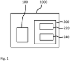
Fig. 1 shows a schematic block diagram of aprinting system 1000 according to the second aspect of the present invention. Theprinting system 1000 comprises aprinter 100 capable of printing multiple images simultaneously and acontroller 200 for theprinter 100. In other words, thecontroller 200 is configured to control theprinter 100, specifically to control a processing, in particular printing, of images by theprinter 100. Thecontroller 200 is an embodiment of the first aspect of the present invention. - The
controller 200 comprises aprocess monitor 220 configured to determine which images of a plurality of images are currently being processed simultaneously by theprinter 100. In particular, the process monitor 220 is configured to determine which images of the plurality of images are currently being printed simultaneously by the printer, that is, marking material related to which images is currently being deposited onto a medium by theprinter 100. - The process monitor 220 may be realized at least partially as hardware and/or at least partially as software, as has been described in the foregoing.
- The process monitor 220 may be configured to determine, for at least one step during the processing of the images by the
printer 100, which images of the plurality of images currently being processed according to that specific step by theprinter 100. One of the steps during the processing of the images by theprinter 100 is the printing itself, that is the application of marking material onto a medium such as paper. Accordingly, the process monitor 220 may be configured to, at least, determine which images of the plurality of images are currently being printed simultaneously by the printer. Alternatively, or additionally, the process monitor 220 may be configured to determine which other steps of the processing of the images are currently being performed simultaneously and for which images. - The
controller 200 also comprises adisplay 240 configured to indicate to a user or operator, based on the determining by the process monitor 220, which images of the plurality of images are currently being processed simultaneously by the printer. Thedisplay 240 may for example be a touch screen display or a liquid crystal display. Thedisplay 240 may be locally connected to theprocess monitor 220. Alternatively, the process monitor 220 and thedisplay 240 may be connected over a network such as the internet. The display may be realized, for example, within an App or a browser window run by a remote computer or mobile device such as a laptop, a smartphone, a tablet computer, a PDA and so on. - The process monitor 220 itself may be realized as a local device in the vicinity of the
printer 100 but may also be realized as a remote device or a remotely run software module, run for example by a remote server such as a cloud server. - As has already been described in the foregoing, the
controller 200 may comprise an error handler, e.g. an error handler software module, which recognizes error states of thecontroller 200, of theprinter 100 or of any other part of theprinting system 1000, and reacts to them. Based on the determining, by the process monitor 220, which images are currently being processed (and, preferably, according to which step of the processing), the error handler may be provided with the information which images have been affected by a certain error state recognized by the error handler. - For example, the error handler may have access to a table that instructs the error handler which error states affect which steps of the processing of images. Accordingly, the error handler may be configured to automatically apply an error handling function in which the error state is removed or alleviated, to all of the images that were being processed in one of the steps affected by the error state.
-
Fig. 2 shows a schematic diagram of an exemplary graphical interface, or a part of a graphical interface, displayed by thedisplay 240. - According to
Fig. 2 , thedisplay 240 shows agraphical representation 242 of a medium which is marked by theprinter 100 for printing the images. For example, the medium may be a sheet of paper or a roll of paper, a roll of a textile or the like. Arranged within saidgraphical representation 242 of the medium,graphical representations mediums 242 may correspond closely, or exactly, to the actual arrangement in which the images are printed onto the medium, for example, according to printing instructions provided by a nesting logic, as will be described in the following with respect toFig. 3 . - As shown in
Fig. 2 , thedisplay 240 is also configured to show agraphical representation 246 of a print swath of a print head of theprinter 100 and/or a graphical representation of a location, specifically a current location, of said print swath. Again, thegraphical representation 246 may be arranged exactly as the actual print swath of the print head of theprinter 100 currently arranged with respect to the images of which the graphical representations 243-245 are displayed. - Information from the
printer 100 where the actual current print swath is located with respect to the images to which the printing instructions relate may be transmitted from theprinter 100 to thecontroller 200 within aprinter output signal 72. - The graphical representations 243-245 of the images may advantageously comprise scaled-down and/or simplified versions of the actual images, such as thumbnails, in order to allow a user or an operator of the
controller 200 to immediately discern which graphical representation 243-245 represents which image. In addition, or alternatively, the graphical representations 243-245 may comprise alphanumerical indications of data related to the images such as file names, dimensions, an order number within a list, and so on. - In the example shown in
Fig. 2 , the user or operator of thecontroller 200 is able to understand immediately that the images represented by thegraphical representations print swath 246 overlaps both of these twographical representations - It will be understood that also images that are currently being processed in other steps than being printed, for example images that are currently being cut or cured or the like, may also be highlighted to the user by the
display 240. For example, those images cut be displayed surrounded by a frame of a certain color, or a symbol indicating cutting or curing could be displayed on top of each image that is currently being cut or cured, respectively. -
Fig. 3 shows a schematic block diagram of aprinting system 1000 in variant from theprinting system 1000 discussed with respect toFig. 1 . - The
controller 200 in the variant according toFig. 3 comprises anesting logic 280 configured to create and/or update printing instructions for theprinter 100 which indicate, usually among other items, in which arrangement theprinter 100 is to print the plurality of images onto the recording medium. - The process monitor 220 may receive a data signal from the
nesting logic 280. Using this data signal from thenesting logic 280, the process monitor 220 may determine which images overlap with any given print swath of a print head of theprinter 100 according to the arrangement indicated by the printing instructions. All images that overlap with one and the same print swath will, accordingly, at some point be processed, in particular printed, simultaneously. When it is determined where the print swath is actually positioned with respect to the arrangement indicated by the printing instructions, it may therefore also be determined, by the process monitor 220, which images are currently being printed simultaneously. - In case that there is data available which of the images is currently, for example in a list of print jobs and/or images, indicated as being the active job, the process monitor 220 may determine that all images which overlap a print swath that also overlaps that image indicated as currently active are currently being processed simultaneously by the
printer 100. - It should be understood that instead of the print swath also other geometrical objects may be used to determine, similarly as described before, which images are currently being processed simultaneously by the printer.
- Other options for determining which images of the plurality of images are currently being processed simultaneously by the
printer 100 will be described in the following. - The
controller 200 of theprinting system 1000 according toFig. 3 may optionally comprise at least oneinterface 260. The at least oneinterface 260 may be configured to receive the plurality of images. The at least oneinterface 260 may also be configured to receive property data indicating properties of theprinter 100 and/or properties of a medium supplied to theprinter 100 for printing thereon. - The
nesting logic 280 may be configured to create and/or update printing instructions for theprinter 100 based on adata signal 77 received from the at least oneinterface 260. The signal may indicate, or contain, any of the property data received by the at least oneinterface 260. Accordingly, thenesting logic 280 may be configured to create and/or update the printing instructions for theprinter 100 based on properties of the received images and/or based on the property data indicated by thesignal 77. - The original printing instructions or the modified printing instructions may be transmitted by the
controller 200 to the printer in, or with, acontroller output signal 71. The printing instructions created and/or updated by thenesting logic 280 indicate to theprinter 100 in which arrangement (e.g. nested in which way) theprinter 100 is to print the plurality of images onto the medium. - For example, the property data may indicate that the medium has a certain width, while the properties of the received images may indicate that some images of the received plurality of images have a width smaller than half the width of the medium such that at least two of said images may be arranged next to each other in the width direction on a medium. In short, the
nesting logic 280 may perform a nesting of all, or at least some of, the received plurality of images. - As has been described, when the
controller 200 comprises thenesting logic 280, the printing instructions based on which the process monitor may determine which images are currently being processed simultaneously by theprinter 100 are created within and by thecontroller 200 itself. As an alternative, thecontroller 200 may be provided with aninterface 260 configured to receive finalized printing instructions which may then be forwarded to the process monitor 220, and optionally also to theprinter 100. - It should be understood that the process monitor 220, the
display 240 and/or thenesting logic 280 may be integrated into one physical device and therefore be comprised within the same housing. However, as an alternative, the process monitor 220, thedisplay 240 and/or thenesting logic 280 may be realized as remote devices connected by a network or as software modules executed by a server removed from the physical location of theprinter 100, or even by a plurality of servers. - For example, the
nesting logic 280 may be realized by a processor and a memory of a cloud server which relates a signal indicating the printing instructions to a mobile phone with a memory and a processor which run the process monitor 220 as an app. Additional information from theprinter 100 where the actual current print swath is located with respect to the images to which the printing instructions relate may be transmitted by theprinter 100 in theprinter output signal 72 to the mobile phone that runs, or provides, theprocess monitor 220. Theprinter output signal 72 may in this case be transmitted e.g. over the internet, over a mobile communications network, a local area network and/or the like. - For example, the data from the
printer 100 may indicate that the current print swath is located 10 cm from the start of the first image according to the printing instructions, or is located a certain number of widths of print swaths from the start of the printing, or that a certain amount of time has passed with continuous printing (from which, given an assumed constant movement speed of the print swath along the medium, again the current location of the print swath may be determined) and so on. - The
controller 200 may comprise auser interface 265 configured to receive an abortion command from a user, the abortion command indicating that processing of at least one of the plurality of images should be aborted, in particular indicating that printing of at least one of the plurality of images should be aborted. Thenesting logic 280 may be configured to update the printing instructions for theprinter 100 to abort the processing, in particular printing, of the at least one of the plurality of images indicated by the abortion command. - For example, a user may press a pause button or in another way indicate that the
printer 100 should pause processing of the plurality of images. Theuser interface 265 may then give the user the option to send the abortion command, optionally specifying parameters of the abortion command such as information about which image should be aborted under any circumstances, which image should not be aborted under any circumstances and for which images it is acceptable either that they are aborted or not aborted. - The
nesting logic 280 may be configured such that, when at least one of the images indicated by the abortion command is one of the images being currently processed, in particular printed, as determined by the process monitor 220, the printing instructions for theprinter 100 are updated such that, of the images being currently processed, in particular printed, only the images indicated by the abortion command are aborted, whereas images not indicated by the abortion command continue to be processed, in particular printed. - In the event that the abortion command comprises information about the processing of which images should be aborted under any circumstances, not aborted under any circumstances or the processing of which is acceptable to be aborted or not aborted, the
nesting logic 280 may update the printing instructions such that the images of which the processing should not be aborted under any circumstances continue to be processed while the images the processing of which was indicated to be aborted under any circumstances are aborted, and wherein, for the images for which both abortion and continued processing is indicated to be acceptable by the abortion command, it is decided on an image-by-image basis whether they are aborted or not, based on specified criteria. Such criteria may include minimizing amount of medium consumed, minimizing time spent processing, in particular printing, minimizing an amount of marking material expended and so on. Several criteria may be used and may be provided with specific weights. -
Fig. 4 shows a schematic diagram of avariant printing system 1000 according to yet another embodiment of the second aspect as well as of avariant controller 200 according to yet another embodiment of the first aspect. Thevariant printing system 1000 ofFig. 4 differs from theprinting system 1000 according toFig. 1 in that it further comprises acutter 300 configured to cut the medium before, during or after theprinter 100 processes or has processed said medium and/or in that theprinting system 1000 ofFig. 4 further comprises acuring unit 400 configured to cure the medium, during or after theprinter 100 processes or has processed said medium. - The
cutter 300 and/or thecuring unit 400 may be separate from theprinter 100, as suggested inFig. 4 . - Alternatively, the
cutter 300 may be provided as a part of theprinter 100, and the cutting performed by thecutter 300 may be considered a part of the processing of the plurality of images by theprinter 100. For example, the processing of the plurality of images may comprise first marking the medium to create the images on the medium and then cutting, using thecutter 300, the medium to individualize the images from one another and/or to trim them. - Similarly, the
curing unit 400 may be provided as a part of theprinter 100, and the curing performed by thecuring unit 400 may be considered a part of the processing of the plurality of images by theprinter 100. For example, the processing of the plurality of images may comprise first marking the medium to create the images on the medium and then curing using the curing unit, the medium to render the marking material on the recording medium inert. When both acutter 300 and acuring unit 400 are present, preferably the medium will be first processed by the curing unit and only thereafter by thecutter 300. - The
controller 200 inFig. 4 comprises acutting monitor 222 configured to determine which, or the vicinity of which, of the plurality of images is currently being cut by thecutter 300. Thedisplay 240 may be configured to indicate to the user the images currently being cut by thecutter 300 based on the determining by the cuttingmonitor 224. - The cutting monitor 222 may be realized at least partially as hardware and/or at least partially as software, as has been described in the foregoing.
- The cutting monitor 222 may be provided as a part of the process monitor 220 or separate from the
process monitor 220. Thecontroller 200 may be configured to provide theprinter 100 not only with printing instructions from anesting logic 280, which may or may not be part of thecontroller 200, but may also be configured to provide thecutter 300 with cutting information indicating where thecutter 300 is to cut the printed medium. - As has been described before with respect to the
nesting logic 280, also the cutting instructions may be created by, or within, thecontroller 200 itself, or may be received by thecontroller 200 from an external element or system to be used and/or to be transmitted to the printer and/or thecutter 300. The cutting monitor 222 may be configured to determine which, or the vicinity of which, of the plurality of images is currently being cut by thecutter 300 based on the cutting instructions and/or based on the printing instructions and/or based on theprinter output signal 71 from theprinter 100 and/or based on acutter output signal 73 transmitted by thecutter 300 to thecontroller 200, in particular specifically to thecutting monitor 222. If thecutter 300 is integrated into theprinter 100, thecutter output signal 73 may be a part of theprinter output signal 71. - The
display 240 may be configured to display to the user graphical representations 242-246 as shown inFig. 2 and show additionally a graphical representation of a position of thecutter 300 with respect to thegraphical representation 242 of the medium which indicate to the user a position at which thecutter 300 is currently positioned with respect to the medium. - The
controller 200 inFig. 4 further comprises acuring monitor 224 configured to determine which, or the vicinity of which, of the plurality of images is currently being cured by thecuring unit 400. Thedisplay 240 may be configured to indicate to the user the images currently being cured by thecuring unit 400 based on the determining by thecuring monitor 224. - The curing monitor 224 may be realized at least partially as hardware and/or at least partially as software, as has been described in the foregoing.
- The curing monitor 224 may be provided as a part of the process monitor 220 or separate from the
process monitor 220. Thecontroller 200 may be configured to provide thecuring unit 400 with curing information indicating where and/or how thecuring unit 400 is to cure the recording medium. For example, certain inks may have to be cured with a higher dosage of radiation and/or longer exposure time and/or with radiation of different wavelengths than other inks. - As has been described before with respect to the
nesting logic 280, also the curing instructions may be created by, or within, thecontroller 200 itself, or may be received by thecontroller 200 from an external element or system to be used and/or to be transmitted to the printer and/or thecuring unit 400. The curing monitor 224 may be configured to determine which of the plurality of images is currently being cured by thecuring unit 400 based on the curing instructions and/or based on the printing instructions and/or based on theprinter output signal 71 from theprinter 100 and/or based on a curingunit output signal 74 transmitted by thecuring unit 400 to thecontroller 200, in particular specifically to thecuring monitor 224. If thecuring unit 400 is integrated into theprinter 100, the curingunit output signal 74 may be a part of theprinter output signal 71. - The
display 240 may be configured to display to the user graphical representations 242-246 as shown inFig. 2 and show additionally a graphical representation of a position of thecuring unit 400 with respect to the graphical representation of the medium 242 which indicate to the user a position at which thecuring unit 400 is currently positioned with respect to the medium. - It should be understood that also for some, or all, possible additional steps during the processing of the images by the
printer 100, corresponding monitoring units may be provided (e.g. as has been described with respect to thecutting monitor 222 and/or the curing monitor 224) and thedisplay 240 may be configured to accordingly display results of the monitoring by those monitoring units, e.g. to indicate which images are currently being processed in the corresponding step of the processing. - For example, a drying monitor may be provided that determines which images are currently being dried by an optional drier of the
printing system 1000, the drier being configured to direct hot and/or cold air along the recording medium. Then, the display may be configured to indicate, using thegraphical representations curing monitor 224 and thecuring unit 400, respectively, in theprinting system 1000. -
Fig. 5 shows a schematic flow diagram illustrating a method according to an embodiment of the third aspect, i.e. a method for controlling a printer. The method according toFig. 5 may be performed using any printing system according to an embodiment of the first aspect, or any controller according to an embodiment of the second aspect. Accordingly, the method ofFig. 5 may be modified and adapted according to all variations and modifications described herein with respect to the printing system according to the first aspect and/or the controller according to the second aspect. In discussing the method illustrating inFig. 5 , reference will also be made to theFigures 1 through 4 as well as to the reference signs therein as and to the corresponding description. - In a step S10, a plurality of images is received, e.g. by the
printing system 1000, in particular by thecontroller 200. - In a step S20, multiple images of the received plurality of images are processed simultaneously by a printer, e.g. the
printer 100 of theprinting system 1000. As has been discussed in the foregoing, such processing may include printing, cutting, curing and the like. - In an optional step S30, additional data may be received, in particular at, or by, the
controller 200. For example, property data indicating properties of theprinter 100 and/or property data indicating properties of a recording medium supplied to theprinter 100 for printing thereon may be received, e.g. as has been described in the foregoing with respect to theinterface 260 of thecontroller 200. Additionally, or alternatively, an abortion command may be received as described with respect to theuser interface 265 in the foregoing. Further additionally or alternatively, aprinter output signal 72, acutter output signal 73 and/or a curingunit output signal 74, each e.g. as described above, may be received. - Some of the additional data received in step S30 may be used to create and/or update, in an optional step S40, printing instructions for the
printer 100, the printing instructions instructing theprinter 100 in which arrangement theprinter 100 is to print the plurality of images onto the recording medium, or even which images theprinter 100 is to print onto the recording medium and how. - In a step S50, it is determined which images of the plurality of images are currently being processed simultaneously by the
printer 100. In particular, it may be determined which images of the plurality of images are currently being printed, which images of the plurality of images are currently being cured (e.g. by thecuring unit 400 as described above) and/or which images of the plurality of images are currently being cut (e.g. by thecutter 300 as described above). The determining S50 may be based on any or all of the additional data that may have been received in the optional step S30, as has been described in the foregoing. Specifically, the printing instructions created and/or updated in the optional step S40 may be used in the determining S50, e.g. as has been described with respect to thenesting logic 280 and the process monitor 220 in the foregoing. - In a step S60, it is indicated to a user, e.g. graphically using the
display 240, which images of the plurality of images have been determined to be currently being processed simultaneously by theprinter 100, or specifically, which images of the plurality of images have been determined to be currently being printed, cured, cut and the like. The indicating S60 to the user is preferably performed visually such as has been described with respect to thedisplay 240 and in connection withFig. 2 in the foregoing. However, other methods of indicating information to the user may be employed additionally or alternatively, such as acoustic and/or haptic signals. -
Fig. 6 shows a schematic block diagram of asoftware medium 500 according to an embodiment of the fourth aspect. Thesoftware medium 500 is preferably a non-volatile software storage medium and comprisesexecutable code 550 configured to, when executed, perform the method according to any embodiment of the third aspect, e.g. as described with respect to theprinting system 1000, thecontroller 200, according to any or all of theFigures 1 to 4 and/or according to any of the variants and modifications of theprinting system 1000, thecontroller 200 and/or of the method described herein. - The
software medium 500 may, specifically, be formed as a CD or a CD-ROM, a DVD or a DVD-ROM, a BluRay disc or a BluRay-ROM disc, a magnetic hard drive, a solid state disk (SSD) hard drive, a USB memory device and so on. - While detailed embodiments of the present invention are disclosed herein, it is to be understood that the disclosed embodiments are merely exemplary of the invention, which can be embodied in various forms. Therefore, specific structural and functional details disclosed herein are not to be interpreted as limiting, but merely as a basis for the claims and as a representative basis for teaching one skilled in the art to variously employ the present invention in virtually any appropriately detailed structure. In particular, features presented and described in separate dependent claims may be applied in combination and any advantageous combination of such claims are herewith disclosed.
- Further, the terms and phrases used herein are not intended to be limiting; but rather, to provide an understandable description of the invention. The terms "a" or "an", as used herein, are defined as one or more than one. The term plurality, as used herein, is defined as two or more than two. The term another, as used herein, is defined as at least a second or more. The terms including and/or having, as used herein, are defined as comprising (i.e., open language).
- It will be evident that the described embodiments may be varied in many ways. All such modifications as would be evident to one skilled in the art starting from what is explicitly described are intended to be included.
- One basic idea of the invention may be summarized as follows: a print controller determines which images of one or more print jobs are currently being processed (such as printed, cured, cut etc.) simultaneously, and indicates the results to a user.
Claims (15)
- A controller (200) for a printer (100) capable of processing multiple images
simultaneously, comprising:a process monitor (220) configured to determine which images of a plurality of images are currently being processed simultaneously by the printer (100); anda display (240) configured to indicate to a user, based on the determining by the process monitor (220), which images of the plurality of images are currently being processed simultaneously by the printer (100). - The controller (200) according to claim 1, further comprising:an error handler configured to determine whether an error has occurred during printing by the printer (100); and further configured to apply an error handling procedure to all of the images that were affected by the occurred error, based on the determining by the process monitor (220).
- The controller (200) according to claim 1 or 2,
wherein the controller (200) further comprises:a cutting monitor (230) configured to determine which, or the vicinity of which, of the plurality of images is currently being cut by a cutter (300); andwherein the display (240) is further configured to indicate to the user the images currently being cut by the cutter (300). - The controller (200) according to any of claims 1 to 3,
wherein the controller (200) further comprises
a curing monitor (240) configured to determine which of the plurality of images is currently being cured by a curing unit (400); and
wherein the display (240) is further configured to indicate to the user the images currently being cured by the curing unit (400). - The controller (200) according to any of claims 1 to 4,
further comprising:at least one interface (260) configured to receive the plurality of images and for receiving property data indicating properties of the printer (100) and/or of a medium supplied to the printer (100) for printing thereon; anda nesting logic (280) configured to create and/or update printing instructions for the printer (100) based on properties of the received images and/or based on the property data, the printing instructions indicating to the printer (100) in which arrangement the printer (100) is to print the plurality of images onto the medium;wherein the process monitor (220) is configured to determine which images of the plurality of images are currently being printed simultaneously using the printing instructions. - The controller (200) according to claim 5, further comprising:a user interface (265) configured to receive an abortion command from a user, the abortion command indicating that processing of at least one of the plurality of images should be aborted;wherein the nesting logic (280) is configured to update the printing instructions for the printer (100) to abort the processing of the at least one of the plurality of images indicated by the abortion command.
- The controller (200) according to claim 6,
wherein the nesting logic (280) is configured such that, when at least one of the images indicated by the abortion command is one of the images being currently processed as determined by the process monitor (220), the printing instructions for the printer (100) are updated such that, of the images being currently processed, only the images indicated by the abortion command are aborted, whereas images not indicated by the abortion command continue to be processed. - The controller (200) according to claim 6 or 7,
wherein the abortion command comprises an indication that at least one of the images is to be finished before printing is aborted; and
wherein the nesting logic (280) is configured such that, when at least one of the images indicated to be finished by the abortion command is one of the images being currently processed as determined by the process monitor (220), the printing instructions for the printer (100) are updated such that, of the images being currently processed, at least the images indicated by the abortion command to be finished are finished before the processing of the at least one of the plurality of images indicated by the abortion command is aborted. - The controller (200) according to any of claims 5 to 8,
wherein the display (240) is further configured to display (240) a graphical representation (243-245) of the plurality of images according to the arrangement of the images indicated by the printing instructions; and
wherein the display (240) unit is further configured to display (240) a graphical indication, based on the determining of the process monitor (220), of which images are currently being processed simultaneously. - A printing system (1000), comprising:a printer (100) capable of printing multiple images simultaneously; anda controller (200) according to any one of claims 1 to 9 operatively coupled to said printer (100).
- The printing system (1000) of claim 10,
wherein the printing system (1000) comprises a cutter (300) and a controller (200) according to claim 3. - The printing system (1000) of claim 10 or 11,
wherein the printing system (1000) comprises a curing unit (400) and a controller (200) according to claim 4. - A method for controlling a printer (100), the method comprising steps of:- receiving (S10) a plurality of images;- processing (S20), by the printer (100), multiple images of the plurality of images simultaneously;- determining (S50) which images of the plurality of images are currently being processed simultaneously by the printer (100); and- indicating (S60) to a user which images of the plurality of images have been determined to be currently being processed simultaneously by the printer (100).
- The method of claim 13, further comprising steps of:- receiving (S30) property data indicating properties of the printer (100) and/or of a medium supplied to the printer (100) for printing thereon;- creating and/or updating (S40) printing instructions for the printer (100) based on properties of the received images and/or based on the property data, the printing instructions indicating to the printer (100) in which arrangement the printer (100) is to print the plurality of images onto the medium;wherein the determining (S50) is performed using the printing instructions.
- A software medium (500) comprising executable program code (550) configured to, when executed, perform the method according to claims 13 or 14.
Applications Claiming Priority (1)
| Application Number | Priority Date | Filing Date | Title |
|---|---|---|---|
| EP17197903 | 2017-10-24 |
Publications (2)
| Publication Number | Publication Date |
|---|---|
| EP3477464A1 true EP3477464A1 (en) | 2019-05-01 |
| EP3477464B1 EP3477464B1 (en) | 2023-02-22 |
Family
ID=60162087
Family Applications (1)
| Application Number | Title | Priority Date | Filing Date |
|---|---|---|---|
| EP18199907.9A Active EP3477464B1 (en) | 2017-10-24 | 2018-10-11 | Controller for a printer, printing system and method for controlling a printer |
Country Status (2)
| Country | Link |
|---|---|
| US (1) | US10572193B2 (en) |
| EP (1) | EP3477464B1 (en) |
Citations (4)
| Publication number | Priority date | Publication date | Assignee | Title |
|---|---|---|---|---|
| US20090059289A1 (en) * | 2007-08-31 | 2009-03-05 | Canon Kabushiki Kaisha | Display system, display method, and storage medium storing display program |
| US20150022845A1 (en) * | 2013-07-22 | 2015-01-22 | Xerox Corporation | Automatically identifying locations of printing defects within printed rolls |
| US20150093049A1 (en) * | 2013-10-01 | 2015-04-02 | Oce-Technologies B.V. | Method for planning digital images to be printed on a roll of media |
| US20160347085A1 (en) * | 2014-02-07 | 2016-12-01 | Agfa Graphics Nv | Manufacturing of decorative workpieces by inkjet |
Family Cites Families (2)
| Publication number | Priority date | Publication date | Assignee | Title |
|---|---|---|---|---|
| EP3039852A1 (en) * | 2013-08-30 | 2016-07-06 | Agfa Graphics NV | Nesting method and apparatus |
| EP3652633B1 (en) * | 2017-07-14 | 2024-03-06 | Canon Production Printing Holding B.V. | Roll-fed printing apparatus, raster image processor, software medium, method for controlling a roll-fed printing apparatus, and method for controlling the raster image processor |
-
2018
- 2018-10-11 EP EP18199907.9A patent/EP3477464B1/en active Active
- 2018-10-16 US US16/161,510 patent/US10572193B2/en active Active
Patent Citations (4)
| Publication number | Priority date | Publication date | Assignee | Title |
|---|---|---|---|---|
| US20090059289A1 (en) * | 2007-08-31 | 2009-03-05 | Canon Kabushiki Kaisha | Display system, display method, and storage medium storing display program |
| US20150022845A1 (en) * | 2013-07-22 | 2015-01-22 | Xerox Corporation | Automatically identifying locations of printing defects within printed rolls |
| US20150093049A1 (en) * | 2013-10-01 | 2015-04-02 | Oce-Technologies B.V. | Method for planning digital images to be printed on a roll of media |
| US20160347085A1 (en) * | 2014-02-07 | 2016-12-01 | Agfa Graphics Nv | Manufacturing of decorative workpieces by inkjet |
Also Published As
| Publication number | Publication date |
|---|---|
| US20190121583A1 (en) | 2019-04-25 |
| EP3477464B1 (en) | 2023-02-22 |
| US10572193B2 (en) | 2020-02-25 |
Similar Documents
| Publication | Publication Date | Title |
|---|---|---|
| EP2942737B1 (en) | Image processing device and program | |
| US9459818B2 (en) | Image forming apparatus with recovery printing function that allows user to designate recovery printing starting page | |
| US9348549B2 (en) | Image forming apparatus, server apparatus, and method of controlling printing of server apparatus | |
| US20150138596A1 (en) | Image forming apparatus, information processing apparatus and control method thereof, and storage medium storing a program | |
| US10209937B2 (en) | Control device and control method of control device | |
| JP5768954B2 (en) | Image forming apparatus, image forming system, and image forming program | |
| EP3075550B1 (en) | Thermal printer | |
| US10572193B2 (en) | Controller for a printer capable of printing multiple images simultaneously | |
| JP2011068022A (en) | Recording device, control method of recording device and program | |
| US8879117B2 (en) | Margin adjustment | |
| CN102520895B (en) | The printer driver of the registration model centered by use case and being separated of application | |
| JP3118120B2 (en) | Image forming apparatus and control method thereof | |
| EP3416104B1 (en) | Roll-fed printing assembly, software medium, and method for controlling a roll-fed printing assembly | |
| JP6390652B2 (en) | Printing device | |
| US7949278B2 (en) | Apparatus for registering a predetermined number of jobs simultaneously | |
| US20190018627A1 (en) | Roll-fed printing apparatus, software medium, and method for controlling a roll-fed printing apparatus | |
| JP2016064535A (en) | Printer | |
| EP3028864B1 (en) | Printing control device, printing device, program, and recording medium | |
| JP2007261191A (en) | Printer | |
| JP2019077183A (en) | Printer device and program | |
| JP2015072580A (en) | Print control unit and program | |
| JPH10151810A (en) | Method for controlling label printer and label printer | |
| EP4119353A1 (en) | Roll-fed printer, software medium and method for double-sided printing on a web | |
| JP2017130082A (en) | Network system, information processing device, control method of information processing device and printer | |
| JP2008126648A (en) | Printer and printing method |
Legal Events
| Date | Code | Title | Description |
|---|---|---|---|
| PUAI | Public reference made under article 153(3) epc to a published international application that has entered the european phase |
Free format text: ORIGINAL CODE: 0009012 |
|
| STAA | Information on the status of an ep patent application or granted ep patent |
Free format text: STATUS: THE APPLICATION HAS BEEN PUBLISHED |
|
| AK | Designated contracting states |
Kind code of ref document: A1 Designated state(s): AL AT BE BG CH CY CZ DE DK EE ES FI FR GB GR HR HU IE IS IT LI LT LU LV MC MK MT NL NO PL PT RO RS SE SI SK SM TR |
|
| AX | Request for extension of the european patent |
Extension state: BA ME |
|
| STAA | Information on the status of an ep patent application or granted ep patent |
Free format text: STATUS: REQUEST FOR EXAMINATION WAS MADE |
|
| 17P | Request for examination filed |
Effective date: 20191104 |
|
| RBV | Designated contracting states (corrected) |
Designated state(s): AL AT BE BG CH CY CZ DE DK EE ES FI FR GB GR HR HU IE IS IT LI LT LU LV MC MK MT NL NO PL PT RO RS SE SI SK SM TR |
|
| RAP1 | Party data changed (applicant data changed or rights of an application transferred) |
Owner name: CANON PRODUCTION PRINTING HOLDING B.V. |
|
| RAP1 | Party data changed (applicant data changed or rights of an application transferred) |
Owner name: CANON PRODUCTION PRINTING HOLDING B.V. |
|
| STAA | Information on the status of an ep patent application or granted ep patent |
Free format text: STATUS: EXAMINATION IS IN PROGRESS |
|
| 17Q | First examination report despatched |
Effective date: 20210318 |
|
| STAA | Information on the status of an ep patent application or granted ep patent |
Free format text: STATUS: EXAMINATION IS IN PROGRESS |
|
| GRAP | Despatch of communication of intention to grant a patent |
Free format text: ORIGINAL CODE: EPIDOSNIGR1 |
|
| STAA | Information on the status of an ep patent application or granted ep patent |
Free format text: STATUS: GRANT OF PATENT IS INTENDED |
|
| INTG | Intention to grant announced |
Effective date: 20220923 |
|
| GRAS | Grant fee paid |
Free format text: ORIGINAL CODE: EPIDOSNIGR3 |
|
| GRAA | (expected) grant |
Free format text: ORIGINAL CODE: 0009210 |
|
| STAA | Information on the status of an ep patent application or granted ep patent |
Free format text: STATUS: THE PATENT HAS BEEN GRANTED |
|
| AK | Designated contracting states |
Kind code of ref document: B1 Designated state(s): AL AT BE BG CH CY CZ DE DK EE ES FI FR GB GR HR HU IE IS IT LI LT LU LV MC MK MT NL NO PL PT RO RS SE SI SK SM TR |
|
| REG | Reference to a national code |
Ref country code: GB Ref legal event code: FG4D |
|
| REG | Reference to a national code |
Ref country code: CH Ref legal event code: EP |
|
| REG | Reference to a national code |
Ref country code: AT Ref legal event code: REF Ref document number: 1549961 Country of ref document: AT Kind code of ref document: T Effective date: 20230315 Ref country code: IE Ref legal event code: FG4D |
|
| REG | Reference to a national code |
Ref country code: DE Ref legal event code: R096 Ref document number: 602018046366 Country of ref document: DE |
|
| REG | Reference to a national code |
Ref country code: NL Ref legal event code: FP |
|
| REG | Reference to a national code |
Ref country code: LT Ref legal event code: MG9D |
|
| REG | Reference to a national code |
Ref country code: AT Ref legal event code: MK05 Ref document number: 1549961 Country of ref document: AT Kind code of ref document: T Effective date: 20230222 |
|
| PG25 | Lapsed in a contracting state [announced via postgrant information from national office to epo] |
Ref country code: RS Free format text: LAPSE BECAUSE OF FAILURE TO SUBMIT A TRANSLATION OF THE DESCRIPTION OR TO PAY THE FEE WITHIN THE PRESCRIBED TIME-LIMIT Effective date: 20230222 Ref country code: PT Free format text: LAPSE BECAUSE OF FAILURE TO SUBMIT A TRANSLATION OF THE DESCRIPTION OR TO PAY THE FEE WITHIN THE PRESCRIBED TIME-LIMIT Effective date: 20230622 Ref country code: NO Free format text: LAPSE BECAUSE OF FAILURE TO SUBMIT A TRANSLATION OF THE DESCRIPTION OR TO PAY THE FEE WITHIN THE PRESCRIBED TIME-LIMIT Effective date: 20230522 Ref country code: LV Free format text: LAPSE BECAUSE OF FAILURE TO SUBMIT A TRANSLATION OF THE DESCRIPTION OR TO PAY THE FEE WITHIN THE PRESCRIBED TIME-LIMIT Effective date: 20230222 Ref country code: LT Free format text: LAPSE BECAUSE OF FAILURE TO SUBMIT A TRANSLATION OF THE DESCRIPTION OR TO PAY THE FEE WITHIN THE PRESCRIBED TIME-LIMIT Effective date: 20230222 Ref country code: HR Free format text: LAPSE BECAUSE OF FAILURE TO SUBMIT A TRANSLATION OF THE DESCRIPTION OR TO PAY THE FEE WITHIN THE PRESCRIBED TIME-LIMIT Effective date: 20230222 Ref country code: ES Free format text: LAPSE BECAUSE OF FAILURE TO SUBMIT A TRANSLATION OF THE DESCRIPTION OR TO PAY THE FEE WITHIN THE PRESCRIBED TIME-LIMIT Effective date: 20230222 Ref country code: AT Free format text: LAPSE BECAUSE OF FAILURE TO SUBMIT A TRANSLATION OF THE DESCRIPTION OR TO PAY THE FEE WITHIN THE PRESCRIBED TIME-LIMIT Effective date: 20230222 |
|
| PG25 | Lapsed in a contracting state [announced via postgrant information from national office to epo] |
Ref country code: SE Free format text: LAPSE BECAUSE OF FAILURE TO SUBMIT A TRANSLATION OF THE DESCRIPTION OR TO PAY THE FEE WITHIN THE PRESCRIBED TIME-LIMIT Effective date: 20230222 Ref country code: PL Free format text: LAPSE BECAUSE OF FAILURE TO SUBMIT A TRANSLATION OF THE DESCRIPTION OR TO PAY THE FEE WITHIN THE PRESCRIBED TIME-LIMIT Effective date: 20230222 Ref country code: IS Free format text: LAPSE BECAUSE OF FAILURE TO SUBMIT A TRANSLATION OF THE DESCRIPTION OR TO PAY THE FEE WITHIN THE PRESCRIBED TIME-LIMIT Effective date: 20230622 Ref country code: GR Free format text: LAPSE BECAUSE OF FAILURE TO SUBMIT A TRANSLATION OF THE DESCRIPTION OR TO PAY THE FEE WITHIN THE PRESCRIBED TIME-LIMIT Effective date: 20230523 Ref country code: FI Free format text: LAPSE BECAUSE OF FAILURE TO SUBMIT A TRANSLATION OF THE DESCRIPTION OR TO PAY THE FEE WITHIN THE PRESCRIBED TIME-LIMIT Effective date: 20230222 |
|
| PG25 | Lapsed in a contracting state [announced via postgrant information from national office to epo] |
Ref country code: SM Free format text: LAPSE BECAUSE OF FAILURE TO SUBMIT A TRANSLATION OF THE DESCRIPTION OR TO PAY THE FEE WITHIN THE PRESCRIBED TIME-LIMIT Effective date: 20230222 Ref country code: RO Free format text: LAPSE BECAUSE OF FAILURE TO SUBMIT A TRANSLATION OF THE DESCRIPTION OR TO PAY THE FEE WITHIN THE PRESCRIBED TIME-LIMIT Effective date: 20230222 Ref country code: EE Free format text: LAPSE BECAUSE OF FAILURE TO SUBMIT A TRANSLATION OF THE DESCRIPTION OR TO PAY THE FEE WITHIN THE PRESCRIBED TIME-LIMIT Effective date: 20230222 Ref country code: DK Free format text: LAPSE BECAUSE OF FAILURE TO SUBMIT A TRANSLATION OF THE DESCRIPTION OR TO PAY THE FEE WITHIN THE PRESCRIBED TIME-LIMIT Effective date: 20230222 Ref country code: CZ Free format text: LAPSE BECAUSE OF FAILURE TO SUBMIT A TRANSLATION OF THE DESCRIPTION OR TO PAY THE FEE WITHIN THE PRESCRIBED TIME-LIMIT Effective date: 20230222 |
|
| PGFP | Annual fee paid to national office [announced via postgrant information from national office to epo] |
Ref country code: NL Payment date: 20230921 Year of fee payment: 6 |
|
| REG | Reference to a national code |
Ref country code: DE Ref legal event code: R097 Ref document number: 602018046366 Country of ref document: DE |
|
| PG25 | Lapsed in a contracting state [announced via postgrant information from national office to epo] |
Ref country code: SK Free format text: LAPSE BECAUSE OF FAILURE TO SUBMIT A TRANSLATION OF THE DESCRIPTION OR TO PAY THE FEE WITHIN THE PRESCRIBED TIME-LIMIT Effective date: 20230222 |
|
| PLBE | No opposition filed within time limit |
Free format text: ORIGINAL CODE: 0009261 |
|
| STAA | Information on the status of an ep patent application or granted ep patent |
Free format text: STATUS: NO OPPOSITION FILED WITHIN TIME LIMIT |
|
| PGFP | Annual fee paid to national office [announced via postgrant information from national office to epo] |
Ref country code: GB Payment date: 20231020 Year of fee payment: 6 |
|
| 26N | No opposition filed |
Effective date: 20231123 |
|
| PG25 | Lapsed in a contracting state [announced via postgrant information from national office to epo] |
Ref country code: SI Free format text: LAPSE BECAUSE OF FAILURE TO SUBMIT A TRANSLATION OF THE DESCRIPTION OR TO PAY THE FEE WITHIN THE PRESCRIBED TIME-LIMIT Effective date: 20230222 |
|
| PGFP | Annual fee paid to national office [announced via postgrant information from national office to epo] |
Ref country code: FR Payment date: 20231026 Year of fee payment: 6 Ref country code: DE Payment date: 20231020 Year of fee payment: 6 |