EP3477360B1 - Stereoscopic image display device and stereoscopic image display method - Google Patents
Stereoscopic image display device and stereoscopic image display method Download PDFInfo
- Publication number
- EP3477360B1 EP3477360B1 EP17819915.4A EP17819915A EP3477360B1 EP 3477360 B1 EP3477360 B1 EP 3477360B1 EP 17819915 A EP17819915 A EP 17819915A EP 3477360 B1 EP3477360 B1 EP 3477360B1
- Authority
- EP
- European Patent Office
- Prior art keywords
- shutters
- mechanical
- rays
- display
- small images
- Prior art date
- Legal status (The legal status is an assumption and is not a legal conclusion. Google has not performed a legal analysis and makes no representation as to the accuracy of the status listed.)
- Active
Links
- 238000000034 method Methods 0.000 title claims description 23
- 238000003384 imaging method Methods 0.000 claims description 3
- 206010047571 Visual impairment Diseases 0.000 description 4
- 230000014759 maintenance of location Effects 0.000 description 4
- 238000005516 engineering process Methods 0.000 description 3
- 239000004973 liquid crystal related substance Substances 0.000 description 3
- 230000003287 optical effect Effects 0.000 description 3
- 230000002776 aggregation Effects 0.000 description 2
- 238000004220 aggregation Methods 0.000 description 2
- 230000000694 effects Effects 0.000 description 2
- 230000003203 everyday effect Effects 0.000 description 2
- 239000011521 glass Substances 0.000 description 2
- 230000002123 temporal effect Effects 0.000 description 2
- 238000010586 diagram Methods 0.000 description 1
- 230000004438 eyesight Effects 0.000 description 1
- 238000012986 modification Methods 0.000 description 1
- 230000004048 modification Effects 0.000 description 1
- 230000004043 responsiveness Effects 0.000 description 1
- 230000001360 synchronised effect Effects 0.000 description 1
- 230000004382 visual function Effects 0.000 description 1
Images


Classifications
-
- G—PHYSICS
- G02—OPTICS
- G02B—OPTICAL ELEMENTS, SYSTEMS OR APPARATUS
- G02B30/00—Optical systems or apparatus for producing three-dimensional [3D] effects, e.g. stereoscopic images
- G02B30/20—Optical systems or apparatus for producing three-dimensional [3D] effects, e.g. stereoscopic images by providing first and second parallax images to an observer's left and right eyes
- G02B30/26—Optical systems or apparatus for producing three-dimensional [3D] effects, e.g. stereoscopic images by providing first and second parallax images to an observer's left and right eyes of the autostereoscopic type
- G02B30/30—Optical systems or apparatus for producing three-dimensional [3D] effects, e.g. stereoscopic images by providing first and second parallax images to an observer's left and right eyes of the autostereoscopic type involving parallax barriers
-
- G—PHYSICS
- G02—OPTICS
- G02B—OPTICAL ELEMENTS, SYSTEMS OR APPARATUS
- G02B30/00—Optical systems or apparatus for producing three-dimensional [3D] effects, e.g. stereoscopic images
- G02B30/20—Optical systems or apparatus for producing three-dimensional [3D] effects, e.g. stereoscopic images by providing first and second parallax images to an observer's left and right eyes
- G02B30/22—Optical systems or apparatus for producing three-dimensional [3D] effects, e.g. stereoscopic images by providing first and second parallax images to an observer's left and right eyes of the stereoscopic type
- G02B30/24—Optical systems or apparatus for producing three-dimensional [3D] effects, e.g. stereoscopic images by providing first and second parallax images to an observer's left and right eyes of the stereoscopic type involving temporal multiplexing, e.g. using sequentially activated left and right shutters
-
- G—PHYSICS
- G02—OPTICS
- G02B—OPTICAL ELEMENTS, SYSTEMS OR APPARATUS
- G02B30/00—Optical systems or apparatus for producing three-dimensional [3D] effects, e.g. stereoscopic images
- G02B30/20—Optical systems or apparatus for producing three-dimensional [3D] effects, e.g. stereoscopic images by providing first and second parallax images to an observer's left and right eyes
- G02B30/26—Optical systems or apparatus for producing three-dimensional [3D] effects, e.g. stereoscopic images by providing first and second parallax images to an observer's left and right eyes of the autostereoscopic type
- G02B30/27—Optical systems or apparatus for producing three-dimensional [3D] effects, e.g. stereoscopic images by providing first and second parallax images to an observer's left and right eyes of the autostereoscopic type involving lenticular arrays
-
- G—PHYSICS
- G02—OPTICS
- G02B—OPTICAL ELEMENTS, SYSTEMS OR APPARATUS
- G02B30/00—Optical systems or apparatus for producing three-dimensional [3D] effects, e.g. stereoscopic images
- G02B30/20—Optical systems or apparatus for producing three-dimensional [3D] effects, e.g. stereoscopic images by providing first and second parallax images to an observer's left and right eyes
- G02B30/26—Optical systems or apparatus for producing three-dimensional [3D] effects, e.g. stereoscopic images by providing first and second parallax images to an observer's left and right eyes of the autostereoscopic type
- G02B30/30—Optical systems or apparatus for producing three-dimensional [3D] effects, e.g. stereoscopic images by providing first and second parallax images to an observer's left and right eyes of the autostereoscopic type involving parallax barriers
- G02B30/31—Optical systems or apparatus for producing three-dimensional [3D] effects, e.g. stereoscopic images by providing first and second parallax images to an observer's left and right eyes of the autostereoscopic type involving parallax barriers involving active parallax barriers
-
- G—PHYSICS
- G03—PHOTOGRAPHY; CINEMATOGRAPHY; ANALOGOUS TECHNIQUES USING WAVES OTHER THAN OPTICAL WAVES; ELECTROGRAPHY; HOLOGRAPHY
- G03B—APPARATUS OR ARRANGEMENTS FOR TAKING PHOTOGRAPHS OR FOR PROJECTING OR VIEWING THEM; APPARATUS OR ARRANGEMENTS EMPLOYING ANALOGOUS TECHNIQUES USING WAVES OTHER THAN OPTICAL WAVES; ACCESSORIES THEREFOR
- G03B35/00—Stereoscopic photography
- G03B35/18—Stereoscopic photography by simultaneous viewing
- G03B35/24—Stereoscopic photography by simultaneous viewing using apertured or refractive resolving means on screens or between screen and eye
-
- H—ELECTRICITY
- H04—ELECTRIC COMMUNICATION TECHNIQUE
- H04N—PICTORIAL COMMUNICATION, e.g. TELEVISION
- H04N13/00—Stereoscopic video systems; Multi-view video systems; Details thereof
- H04N13/30—Image reproducers
- H04N13/302—Image reproducers for viewing without the aid of special glasses, i.e. using autostereoscopic displays
- H04N13/31—Image reproducers for viewing without the aid of special glasses, i.e. using autostereoscopic displays using parallax barriers
- H04N13/315—Image reproducers for viewing without the aid of special glasses, i.e. using autostereoscopic displays using parallax barriers the parallax barriers being time-variant
-
- H—ELECTRICITY
- H04—ELECTRIC COMMUNICATION TECHNIQUE
- H04N—PICTORIAL COMMUNICATION, e.g. TELEVISION
- H04N13/00—Stereoscopic video systems; Multi-view video systems; Details thereof
- H04N13/30—Image reproducers
- H04N13/349—Multi-view displays for displaying three or more geometrical viewpoints without viewer tracking
- H04N13/354—Multi-view displays for displaying three or more geometrical viewpoints without viewer tracking for displaying sequentially
Definitions
- the present invention is related to a stereoscopic image display device and a stereoscopic image display method that enable a stereoscopic image (a three-dimensional image) to be viewed with a similar feeling to everyday life without the use of special glasses.
- Stereoscopic image display methods are roughly classified into a method employing a two-viewpoint system that realizes stereoscopic vision by reproducing binocular parallax and convergence, a method employing a multi-viewpoint system that presents, by using lenticular lenses or the like, to left and right eyes multi-view images that are laterally arrayed, and a method employing a spatial image reproducing system that forms a stereoscopic image in space by using data (images) that have recorded optical spatial images of an object (e.g. refer to Non Patent Literature 1).
- the method employing the spatial image reproducing system is regarded as an ideal stereoscopic image display method that satisfies all factors with which humans perceive stereoscopic effect based on their visual functions (e.g. refer to Non Patent Literature 2).
- Patent Literature 1 a stereoscopic image display method in which a display control panel having a large number of minute light-transmission portions is provided, behind the display control panel, a group of image display panels, which includes a plurality of image display panels displaying a large number of small images of an object viewed from positions of the respective minute light-transmission portions, is disposed, the minute light-transmission portions are made to rapidly sequentially selectively allow light to pass through, and at the same time, the small images are displayed at positions on the image display panels corresponding to the minute light-transmission portions that have become to allow light to pass through, is suggested.
- a three-dimensional stereoscopic image display device including: a plurality of image reproduction panels respectively displaying a plurality of group images, in each of which, a large number of small images to become a base of a stereoscopic image are displayed side by side at a same time in a state of not overlapping, and an object is viewed from positions substantially slightly different from each other; an image display panel sequentially displaying in a time-division manner the group images respectively displayed on the plurality of image reproduction panels; and a display control panel disposed in front of the image display panel, having a plurality of group minute light-transmission portions each opening and closing in synchronization with each of the small images of the group images displayed on the image display panel in a time-division manner, wherein the group minute light-transmission portions each have a large number of minute light-transmission portions each of which is in a pinhole-like state or a slit-like state, is suggested.
- a three-dimensional video display including: a video display panel for displaying a video, a dot-shaped light transmitter forming panel having light transmitters on which video light from the video display panel is incident arranged therein in the shape of a plane with predetermined spacing, and shutter means for changing the position of the light transmitter in the plane, is suggested.
- the plurality of image reproduction panels each displaying the group images are disposed on the back side of the image display panel.
- the present invention has been made in consideration of the above circumstances, and has as its object to provide a stereoscopic image display device and a stereoscopic image display method that enable a stereoscopic image (three-dimensional image) having high image quality and containing a large amount of information to be viewed with a similar feeling to everyday life without the use of special glasses.
- a stereoscopic image display device according to a first aspect of the present invention is described in claim 1 and a stereoscopic image display method according to a second aspect of the present invention is described in claim 10.
- the number of the display for displaying the small images is only one, thus it is possible to make the stereoscopic image display device compact. Also, it is possible by means of the first mechanical shutters to extract at a high speed by time-dividing the rays output from the small images as the partial rays each output from the plurality of partial regions. This makes it possible to reduce the spatial and temporal limitations when using the stereoscopic image display device and when applying the stereoscopic image display method.
- the rays output from the small images are extracted in a time-division manner as the partial rays output from the partial regions of the small images by using the first mechanical shutters, it is possible to prevent the partial rays, which are each output from the partial regions of the small images next to each other displayed on the display, from overlapping each other in space, and it is possible to extract the partial rays not including noise content.
- the rays reconstructed from the partial rays also do not include noise content, and thus, this makes it possible to form a stereoscopic image without distortions.
- the partial rays are extracted by using the first mechanical shutters, it is possible to prevent color tone changes of the partial rays and to suppress attenuation of light quantity of the partial rays, and also, since the rays are reconstructed from the partial rays by using the second mechanical shutters, it is possible to prevent color tone changes of the rays and to suppress attenuation of light quantity of the rays; therefore, a bright stereoscopic image with accurate color tone can be obtained.
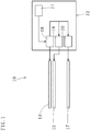
- a stereoscopic image display device (10) includes a display (12) displaying side by side a plurality of small images (11), each of which containing three-dimensional display data, to convert the three-dimensional display data into rays and output the rays from each of the small images (11).
- a display (12) displaying side by side a plurality of small images (11), each of which containing three-dimensional display data, to convert the three-dimensional display data into rays and output the rays from each of the small images (11).
- a plurality of partial regions (13) are provided, and in front of the display (12) a first mechanical shutter panel (15) having first mechanical shutters (14) disposed so as to correspond to positions of the small images (11) displayed on the display (12) is provided.
- the first mechanical shutters (14) extract in a time-division manner the rays output from each of the small images (11) as partial rays each output from the plurality of partial regions (13) and transmit the partial rays forward. Also, in front of the first mechanical shutters (14) a second mechanical shutter panel (17) having second mechanical shutters (16) disposed so as to correspond to the positions of the small images (11) displayed on the display (12) is provided. The second mechanical shutters (16) transmit forward the partial rays extracted in a time-division manner per each of the small images (11), reconstruct the partial rays as the rays, and converge each of the reconstructed rays in front to form a stereoscopic image (three-dimensional image).
- the stereoscopic image display device (10) includes a control unit (22) provided with: an image displaying means (18) for displaying on the display (12) the small images (11) containing the three-dimensional display data; a first mechanical shutter operating means (19) for positioning the first mechanical shutters (14) such that the first mechanical shutters (14) correspond to the positions of the small images (11) displayed on the display (12) and performing on/off operations (open/close operations) of the first mechanical shutters (14); a second mechanical shutter operating means (20) for positioning the second mechanical shutters (16) such that a light axis L exists at a central portion of each of the small images (11) displayed on the display (12) and performing on/off operations of the second mechanical shutters (16) such that off-time (off-time: when a shutter is closed) of the second mechanical shutters (16) synchronizes with off-time of the first mechanical shutters (14); and a small image making means (21) for making the small images (11) containing the three-dimensional display data.
- a control unit (22) provided with: an image
- the number of pixels of the display (12) is preferably equal to or more than 4,000 pixels in a transverse (horizontal) direction, and equal to or more than 2,000 pixels in a longitudinal (perpendicular) direction (i.e. it is preferable to be a display having the number of pixels of 4K or more, more preferably 8K or more). This makes it possible to display many high-definition small images (small images each containing big three-dimensional display data) side by side on the one display (12) and to form a high-resolution three-dimensional image.
- the first mechanical shutters (14) are composed of a plurality of MEMS shutters (micro mechanical shutters based on Micro Electro-Mechanical System technology). This allows, for example, the MEMS shutters each having a same size as each of the pixels of the display (12) to be arranged in the first mechanical shutter panel (15) in accord with disposition of the pixels of the display (12) (to be disposed with a same density as a pixel density of the display (12)).
- MEMS shutters micro mechanical shutters based on Micro Electro-Mechanical System technology
- the selected MEMS shutters serve as the first mechanical shutters (14) having same shapes as the partial regions (13).
- the second mechanical shutters (16) are composed of a plurality of the MEMS shutters. This allows, for example, the MEMS shutters each having the same size as each of the pixels of the display (12) to be arranged in the second mechanical shutter panel (17) in accord with the disposition of the pixels of the display (12). Therefore, by selecting some of the MEMS shutters located within a range corresponding to a central portion of each of the small images (11) displayed on the display (12) from the plurality of MEMS shutters disposed in the second mechanical shutter panel (17), it is possible to make the selected MEMS shutters serve as the second mechanical shutters (16) positioned such that the light axis L passes through the central portion of each of the small images (11).
- the first mechanical shutters (14) As optical shutters, it is possible to extract the partial rays in which the color tone changes are prevented and the attenuation of light quantity is suppressed from the rays output from each of the small images.
- the second mechanical shutters (16) as the optical shutters, it is possible to transmit the partial rays toward the front of the second mechanical shutter panel (17) while preventing the color tone changes and suppressing the attenuation of light quantity. This makes it possible to reconstruct the rays in which there is no color tone change and the attenuation of light quantity is suppressed comparing to the rays output from each of the small images (11) by using the partial rays extracted from each of the small images (11), and converge each of the rays.
- the first mechanical shutter panel (15) be disposed so as to abut on the display (12) or closely disposed so as to have a space of equal to or less than 500 ⁇ m with respect to the display (12).
- a distance between the display (12) and the second mechanical shutter panel (17) is decided based on the ray route information in the three-dimensional display data contained in each of the small images (11) (such that the partial rays output from the partial regions (13) of each of the small images (11) can pass in a same manner through the second mechanical shutters (16) toward the front of the second mechanical shutter panel (17)).
- one of the first mechanical shutters (14) corresponding to a position of one of the partial regions (13) selected from the plurality of partial regions (13) provided in each of the small images (11) becomes on-time. That is, each time the second mechanical shutters (16) are switched on or off, a different one of the partial regions (13) is sequentially selected from the plurality of partial regions (13) provided in each of the small images (11), and one of the first mechanical shutters (14) corresponding to the selected partial region (13) becomes on-time while synchronizing with on-time of the second mechanical shutters (16).
- the first mechanical shutters (14a) corresponding to positions of a plurality (four, in Fig. 3 ) of the partial regions (13a) that are located at positions away from each other (for example, at least not adjacent positions) may become on-time. That is, it may be that in the same way as above, each time the second mechanical shutters (16) are switched on or off, a plurality of the first mechanical shutters (14a) located at different positions away from each other are sequentially selected, and the selected first mechanical shutters (14a) become on-time while synchronizing with on-time of the second mechanical shutters (16).
- each of the second mechanical shutters (16) may be a pinhole-like state, or, as shown in Fig. 4 , each of the second mechanical shutters (16a) may be a slit-like state (the light axis L passes through the central portion of each of the small images (11)).
- each of the second mechanical shutters (16) is a pinhole-like state
- the partial rays entered from an inlet side (the first mechanical shutter panel (15) side) of each of the second mechanical shutters (16) spread out in a light cone shape when going out from an outlet side of each of the second mechanical shutters (16) (toward the front of the second mechanical shutter panel (17)).
- the rays reconstructed from the partial rays also spread out in a light cone shape, and thus, a stereoscopic image having parallax information in overall directions such as horizontal, vertical, and oblique directions is formed.
- each of the second mechanical shutters (16a) is in a slit-like state
- the partial rays entered from an inlet side of each of the second mechanical shutters (16a) spread out when going out from an outlet side of each of the second mechanical shutters (16a), on each of planes parallel to a width direction of the slit, in a fan shape having a base portion at the outlet side of each of the second mechanical shutters (16a).
- the rays reconstructed from the partial rays also spread out in the fan shapes along the longitudinal direction of each of the second mechanical shutters (16a), and thus, a stereoscopic image having parallax information only in the width direction of the second mechanical shutters (16a) is formed. Therefore, to observe the stereoscopic image, an observer must be located such that their eyes are side-by-side along the width direction of the second mechanical shutters (16a), and thus, a limitation occurs for observing the stereoscopic image.
- the image displaying means (18) of the control unit (22) is configured by loading into a computer a program, which includes a small image displaying function for reading the plurality of three-dimensional display data, converting each of the data into a signal for displaying the small images, and inputting the signals to the display (12).
- a dedicated circuit for converting the three-dimensional display data into the signals for displaying the small images may be connected to a signal input side of the display (12). By using the dedicated circuit, it is possible to increase the speed of displaying the small images.
- the first mechanical shutter operating means (19) of the control unit (22) is configured by loading into a computer a program, which includes a MEMS shutter operating function for obtaining, from the image displaying means (18), positional information of pixels used for displaying each of the small images (11) displayed on the display (12) and inputting driving signals that, with respect to each of the MEMS shutters in the first mechanical shutter panel (15), turn on in a time-division manner as the first mechanical shutters (14) the plurality of MEMS shutters located within ranges each corresponding to the displaying ranges of the plurality of partial regions (13) provided in each of the small images (11) and at the same time, turn off all the rest of the MEMS shutters.
- a MEMS shutter operating function for obtaining, from the image displaying means (18), positional information of pixels used for displaying each of the small images (11) displayed on the display (12) and inputting driving signals that, with respect to each of the MEMS shutters in the first mechanical shutter panel (15), turn on in a time-division manner as the first mechanical shutter
- the second mechanical shutter operating means (20) of the control unit (22) is configured by loading into a computer a program, which includes a MEMS shutter operating function for obtaining, from the image displaying means (18), the positional information of the pixels used for displaying each of the small images (11) displayed on the display (12), and with respect to each of the MEMS shutters in the second mechanical shutter panel (17), turning on or off the plurality of MEMS shutters located within a range corresponding to the central portion of each of the small images (11) in synchronization with on-time and off-time of the plurality of MEMS shutters composing the first mechanical shutters (14).
- a MEMS shutter operating function for obtaining, from the image displaying means (18), the positional information of the pixels used for displaying each of the small images (11) displayed on the display (12), and with respect to each of the MEMS shutters in the second mechanical shutter panel (17), turning on or off the plurality of MEMS shutters located within a range corresponding to the central portion of each of the small images (11) in synchronization with on-
- the small image making means (21) of the control unit (22) is configured by loading into a computer, for example, a computer graphics function for making images of a three-dimensional object as three-dimensional display data by moving a virtual camera in a three-dimensional space.
- the small image making means (21) by loading into a computer a function for obtaining image data by imaging through an imaging means (e.g. a stereo camera) the object to become a base of a stereoscopic image supposed to be displayed, extracting, from the image data, polygons composing a surface of the object viewed from viewpoints of the stereo camera, and obtaining, as the three-dimensional display data, vertex coordinates of the extracted polygons, connection information about the vertexes of the polygons next to each other, and color information of each of the polygons.
- an imaging means e.g. a stereo camera
- a stereoscopic image display method using a stereoscopic image display device (10) according to an embodiment of the present invention will be described next.
- the stereoscopic image display method comprises a step of displaying side by side on a display (12) a plurality of small images (11), each of which containing three-dimensional display data, to convert the three-dimensional display data into rays and output the rays from each of the small images (11); a step of extracting the rays in a time-division manner as partial rays each output from a plurality of partial regions (13) provided in the small images (11) and transmitting the partial rays toward the front of a first mechanical shutter panel (15) by using first mechanical shutters (14) disposed in front of the display (12) so as to correspond to positions of the small images (11) displayed on the display (12); and a step of transmitting the partial rays extracted in a time-division manner per each of the small images (11) toward the front of a second mechanical shutter panel (17), reconstructing the partial rays as the rays, and converging each of the reconstructed rays, by using second mechanical shutters (16
- the rays output from each of the small images (11) are extracted as the partial rays output from the partial regions (13) of each of the small images (11) by using the first mechanical shutters (14), it is possible to prevent color tone changes of the partial rays, and besides, to suppress attenuation of light quantity of the partial rays. Further, even if the small images (11) next to each other are displayed on the display (12) being closely adjacent, the partial rays output from each of the partial regions (13) of the small images (11) next to each other each have different ray routes, and thus, the partial rays never cross (overlap) each other in space. Therefore, the extracted partial rays do not include noise content.
- the number of time-divisions i.e. the number of the partial regions are decided in consideration of the speed of opening and closing the first mechanical shutters (14) such that the partial rays from all the partial regions can be extracted within the afterimage retention time of the eye. Also, off-time of the second mechanical shutters (16) is synchronized with off-time of the first mechanical shutters (14) .
- Each of the rays then diffuses forward after being converged at the position S, and thus, if observing each of the rays that diffuses from the front, virtual object points emitting each of the diffusing rays can be seen at the position S where each of the rays are converged.
- a stereoscopic image As an aggregation of the virtual object points.
- the rays diffusing from the aggregation of the virtual object points have a same quality as the rays output from each of the small images (11), the three-dimensional image to be observed becomes a high-definition image which is bright and with no distortion.
- the display and the first mechanical shutter panel are disposed so as to abut on each other
- it may be a structure where the display and the first mechanical shutter panel are integrated, that is, where the MEMS shutters are respectively provided on the pixels of the display and the MEMS shutters are made to serve as the first mechanical shutters.
- the stereoscopic image display device and the stereoscopic image display method are configured by using the first and second mechanical shutters (for example, the MEMS shutters), it is conceivable to use liquid crystal shutters as the first and second mechanical shutters (in this case, interpret "mechanical shutters” as “liquid crystal shutters”).
- the mechanical shutters have a quicker responsiveness comparing to the liquid crystal shutters and can obtain a more vivid and precise stereoscopic image.
- the present invention has applicability as a stereoscopic image display device for video game consoles and medical use, and also as a stereoscopic image display method used at video game arcades, amusement parks, movie theaters, and medical institutions.
Description
- The present invention is related to a stereoscopic image display device and a stereoscopic image display method that enable a stereoscopic image (a three-dimensional image) to be viewed with a similar feeling to everyday life without the use of special glasses.
- Stereoscopic image display methods are roughly classified into a method employing a two-viewpoint system that realizes stereoscopic vision by reproducing binocular parallax and convergence, a method employing a multi-viewpoint system that presents, by using lenticular lenses or the like, to left and right eyes multi-view images that are laterally arrayed, and a method employing a spatial image reproducing system that forms a stereoscopic image in space by using data (images) that have recorded optical spatial images of an object (e.g. refer to Non Patent Literature 1). Of these methods, the method employing the spatial image reproducing system is regarded as an ideal stereoscopic image display method that satisfies all factors with which humans perceive stereoscopic effect based on their visual functions (e.g. refer to Non Patent Literature 2).
- As a method employing the spatial image reproducing system for displaying a sharp stereoscopic image with a wide viewing angle, for example, in Patent Literature 1, a stereoscopic image display method in which a display control panel having a large number of minute light-transmission portions is provided, behind the display control panel, a group of image display panels, which includes a plurality of image display panels displaying a large number of small images of an object viewed from positions of the respective minute light-transmission portions, is disposed, the minute light-transmission portions are made to rapidly sequentially selectively allow light to pass through, and at the same time, the small images are displayed at positions on the image display panels corresponding to the minute light-transmission portions that have become to allow light to pass through, is suggested.
- Also, for example, in Patent Literature 2, a three-dimensional stereoscopic image display device including: a plurality of image reproduction panels respectively displaying a plurality of group images, in each of which, a large number of small images to become a base of a stereoscopic image are displayed side by side at a same time in a state of not overlapping, and an object is viewed from positions substantially slightly different from each other; an image display panel sequentially displaying in a time-division manner the group images respectively displayed on the plurality of image reproduction panels; and a display control panel disposed in front of the image display panel, having a plurality of group minute light-transmission portions each opening and closing in synchronization with each of the small images of the group images displayed on the image display panel in a time-division manner, wherein the group minute light-transmission portions each have a large number of minute light-transmission portions each of which is in a pinhole-like state or a slit-like state, is suggested. And, for example, in Patent Literature 3, a three-dimensional video display including: a video display panel for displaying a video, a dot-shaped light transmitter forming panel having light transmitters on which video light from the video display panel is incident arranged therein in the shape of a plane with predetermined spacing, and shutter means for changing the position of the light transmitter in the plane, is suggested.
-
- Patent Literature 1:
Japanese Unexamined Patent Application Publication No. H9-33858 - Patent Literature 2:
Japanese Patent No. 4744743 - Patent Literature 3:
Japanese Unexamined Patent Application Publication No. 2002-287089 -
- Non Patent Literature 1: Y. Iwadate "Overview of Three-Dimensional Image Technology" NHK STRL. R&D, 2014.3, Vol. 144, pp. 4-9
- Non Patent Literature 2: T. Mishina "Overview of Integral Method" NHK STRL. R&D, 2014.3, Vol. 144, pp. 10-17
- However, as to the stereoscopic image display method set forth in Patent Literature 1, to form a high-definition stereoscopic image, it is necessary to display a large number of the small images within an afterimage retention time of the eye. That is, the small images displayed on the image display panels need to be switched in a short period of time. However, there is a limitation on the image display switching speed of the image display panels, and thus, the group of image display panels including the plurality of image display panels is disposed behind the display control panel, and of the image display panels each displaying the small images in advance, the image display panels displaying the small images corresponding to the minute light-transmission portions, which have become to allow light to pass through, of the display control panel are selected.
- Also, as to the three-dimensional stereoscopic image display device set forth in Patent Literature 2, as is the case in Patent Literature 1, the plurality of image reproduction panels each displaying the group images are disposed on the back side of the image display panel.
- As a result, problems arise in which the back side of the display control panel increases in size for the stereoscopic image display device set forth in Patent Literature 1, and the back side of the image display panel increases in size for the three-dimensional stereoscopic image display device set forth in Patent Literature 2. Therefore, there is a problem that spatial and temporal limitations arise for use (utilization) of the devices.
- As to the three-dimensional video display set forth in Patent Literature 3, since the dot-shaped light transmitter forming panel includes the dot-shaped light transmitters, there is a problem that the three-dimensional video to be displayed becomes dark.
- The present invention has been made in consideration of the above circumstances, and has as its object to provide a stereoscopic image display device and a stereoscopic image display method that enable a stereoscopic image (three-dimensional image) having high image quality and containing a large amount of information to be viewed with a similar feeling to everyday life without the use of special glasses.
- In order to achieve the above object, a stereoscopic image display device according to a first aspect of the present invention is described in claim 1 and a stereoscopic image display method according to a second aspect of the present invention is described in
claim 10. - In the stereoscopic image display device according to the first aspect of the present invention and the stereoscopic image display method according to the second aspect of the present invention, the number of the display for displaying the small images is only one, thus it is possible to make the stereoscopic image display device compact. Also, it is possible by means of the first mechanical shutters to extract at a high speed by time-dividing the rays output from the small images as the partial rays each output from the plurality of partial regions. This makes it possible to reduce the spatial and temporal limitations when using the stereoscopic image display device and when applying the stereoscopic image display method.
- Also, in the stereoscopic image display device according to the first aspect of the present invention and the stereoscopic image display method according to the second aspect of the present invention, since the rays output from the small images are extracted in a time-division manner as the partial rays output from the partial regions of the small images by using the first mechanical shutters, it is possible to prevent the partial rays, which are each output from the partial regions of the small images next to each other displayed on the display, from overlapping each other in space, and it is possible to extract the partial rays not including noise content. As a result, the rays reconstructed from the partial rays also do not include noise content, and thus, this makes it possible to form a stereoscopic image without distortions.
- Moreover, since the partial rays are extracted by using the first mechanical shutters, it is possible to prevent color tone changes of the partial rays and to suppress attenuation of light quantity of the partial rays, and also, since the rays are reconstructed from the partial rays by using the second mechanical shutters, it is possible to prevent color tone changes of the rays and to suppress attenuation of light quantity of the rays; therefore, a bright stereoscopic image with accurate color tone can be obtained.
-
-
Fig. 1 is a block diagram showing a stereoscopic image display device according to an embodiment of the present invention. -
Fig. 2 is an oblique perspective figure showing a structure of the stereoscopic image display device. -
Fig. 3 is an oblique perspective figure showing another structure of the stereoscopic image display device. -
Fig. 4 is an oblique perspective figure showing still another structure of the stereoscopic image display device. Description of Embodiment - An embodiment of the present invention will be described next with reference to the accompanying drawings to provide an understanding of the present invention.
- As shown in
Figs. 1 and2 , a stereoscopic image display device (10) according to an embodiment of the present invention includes a display (12) displaying side by side a plurality of small images (11), each of which containing three-dimensional display data, to convert the three-dimensional display data into rays and output the rays from each of the small images (11). In each of the small images (11) a plurality of partial regions (13) are provided, and in front of the display (12) a first mechanical shutter panel (15) having first mechanical shutters (14) disposed so as to correspond to positions of the small images (11) displayed on the display (12) is provided. The first mechanical shutters (14) extract in a time-division manner the rays output from each of the small images (11) as partial rays each output from the plurality of partial regions (13) and transmit the partial rays forward. Also, in front of the first mechanical shutters (14) a second mechanical shutter panel (17) having second mechanical shutters (16) disposed so as to correspond to the positions of the small images (11) displayed on the display (12) is provided. The second mechanical shutters (16) transmit forward the partial rays extracted in a time-division manner per each of the small images (11), reconstruct the partial rays as the rays, and converge each of the reconstructed rays in front to form a stereoscopic image (three-dimensional image). - Further, the stereoscopic image display device (10) includes a control unit (22) provided with: an image displaying means (18) for displaying on the display (12) the small images (11) containing the three-dimensional display data; a first mechanical shutter operating means (19) for positioning the first mechanical shutters (14) such that the first mechanical shutters (14) correspond to the positions of the small images (11) displayed on the display (12) and performing on/off operations (open/close operations) of the first mechanical shutters (14); a second mechanical shutter operating means (20) for positioning the second mechanical shutters (16) such that a light axis L exists at a central portion of each of the small images (11) displayed on the display (12) and performing on/off operations of the second mechanical shutters (16) such that off-time (off-time: when a shutter is closed) of the second mechanical shutters (16) synchronizes with off-time of the first mechanical shutters (14); and a small image making means (21) for making the small images (11) containing the three-dimensional display data. This will be explained in details below.
- The number of pixels of the display (12) is preferably equal to or more than 4,000 pixels in a transverse (horizontal) direction, and equal to or more than 2,000 pixels in a longitudinal (perpendicular) direction (i.e. it is preferable to be a display having the number of pixels of 4K or more, more preferably 8K or more). This makes it possible to display many high-definition small images (small images each containing big three-dimensional display data) side by side on the one display (12) and to form a high-resolution three-dimensional image.
- The first mechanical shutters (14) are composed of a plurality of MEMS shutters (micro mechanical shutters based on Micro Electro-Mechanical System technology). This allows, for example, the MEMS shutters each having a same size as each of the pixels of the display (12) to be arranged in the first mechanical shutter panel (15) in accord with disposition of the pixels of the display (12) (to be disposed with a same density as a pixel density of the display (12)). Therefore, by selecting some of the MEMS shutters according to positions and dimensions (shapes) of the partial regions (13) provided in each of the small images (11) from the plurality of MEMS shutters disposed in the first mechanical shutter panel (15), it is possible to make the selected MEMS shutters serve as the first mechanical shutters (14) having same shapes as the partial regions (13).
- The second mechanical shutters (16) are composed of a plurality of the MEMS shutters. This allows, for example, the MEMS shutters each having the same size as each of the pixels of the display (12) to be arranged in the second mechanical shutter panel (17) in accord with the disposition of the pixels of the display (12). Therefore, by selecting some of the MEMS shutters located within a range corresponding to a central portion of each of the small images (11) displayed on the display (12) from the plurality of MEMS shutters disposed in the second mechanical shutter panel (17), it is possible to make the selected MEMS shutters serve as the second mechanical shutters (16) positioned such that the light axis L passes through the central portion of each of the small images (11).
- By using the first mechanical shutters (14) as optical shutters, it is possible to extract the partial rays in which the color tone changes are prevented and the attenuation of light quantity is suppressed from the rays output from each of the small images. Also, by using the second mechanical shutters (16) as the optical shutters, it is possible to transmit the partial rays toward the front of the second mechanical shutter panel (17) while preventing the color tone changes and suppressing the attenuation of light quantity. This makes it possible to reconstruct the rays in which there is no color tone change and the attenuation of light quantity is suppressed comparing to the rays output from each of the small images (11) by using the partial rays extracted from each of the small images (11), and converge each of the rays.
- To accurately extract in a time-division manner the partial rays output from the partial regions (13) provided in the small images (11), it is preferable that the first mechanical shutter panel (15) be disposed so as to abut on the display (12) or closely disposed so as to have a space of equal to or less than 500 µm with respect to the display (12).
- Also, a distance between the display (12) and the second mechanical shutter panel (17) is decided based on the ray route information in the three-dimensional display data contained in each of the small images (11) (such that the partial rays output from the partial regions (13) of each of the small images (11) can pass in a same manner through the second mechanical shutters (16) toward the front of the second mechanical shutter panel (17)).
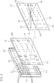
- Here, as shown in
Fig. 2 , when the second mechanical shutters (16) are on-time (on-time: when a shutter is open), one of the first mechanical shutters (14) corresponding to a position of one of the partial regions (13) selected from the plurality of partial regions (13) provided in each of the small images (11) becomes on-time. That is, each time the second mechanical shutters (16) are switched on or off, a different one of the partial regions (13) is sequentially selected from the plurality of partial regions (13) provided in each of the small images (11), and one of the first mechanical shutters (14) corresponding to the selected partial region (13) becomes on-time while synchronizing with on-time of the second mechanical shutters (16). This makes it possible to extract in a time-division manner only the partial rays of the one partial region (13) selected from the plurality of partial regions (13) provided in each of the small images (11). - Alternatively, as shown in
Fig. 3 , when the second mechanical shutters (16) are on-time, the first mechanical shutters (14a) corresponding to positions of a plurality (four, inFig. 3 ) of the partial regions (13a) that are located at positions away from each other (for example, at least not adjacent positions) may become on-time. That is, it may be that in the same way as above, each time the second mechanical shutters (16) are switched on or off, a plurality of the first mechanical shutters (14a) located at different positions away from each other are sequentially selected, and the selected first mechanical shutters (14a) become on-time while synchronizing with on-time of the second mechanical shutters (16). In this case, it is possible to extract in a time-division manner, from the plurality of partial regions (13a) provided in each of the small images (11a), the partial rays of the simultaneously-selected two or more (four, inFig. 3 ) partial regions (13a) each located at different positions. By making, in this manner, the plurality of first mechanical shutters (14a) located at positions away from each other simultaneously become on-time when the second mechanical shutters (16) are on-time, it is possible to extract the partial rays from all the partial regions (13a) within the afterimage retention time of the eye (for example, 1/60 sec to 1/30 sec) even if a large number of the partial regions (13a) are provided in each of the small images (11a). - As shown in
Figs. 2 and3 , each of the second mechanical shutters (16) may be a pinhole-like state, or, as shown inFig. 4 , each of the second mechanical shutters (16a) may be a slit-like state (the light axis L passes through the central portion of each of the small images (11)). - In the case where each of the second mechanical shutters (16) is a pinhole-like state, the partial rays entered from an inlet side (the first mechanical shutter panel (15) side) of each of the second mechanical shutters (16) spread out in a light cone shape when going out from an outlet side of each of the second mechanical shutters (16) (toward the front of the second mechanical shutter panel (17)). As a result, the rays reconstructed from the partial rays also spread out in a light cone shape, and thus, a stereoscopic image having parallax information in overall directions such as horizontal, vertical, and oblique directions is formed.
- Whereas, in the case where each of the second mechanical shutters (16a) is in a slit-like state, the partial rays entered from an inlet side of each of the second mechanical shutters (16a) spread out when going out from an outlet side of each of the second mechanical shutters (16a), on each of planes parallel to a width direction of the slit, in a fan shape having a base portion at the outlet side of each of the second mechanical shutters (16a).
- As a result, the rays reconstructed from the partial rays also spread out in the fan shapes along the longitudinal direction of each of the second mechanical shutters (16a), and thus, a stereoscopic image having parallax information only in the width direction of the second mechanical shutters (16a) is formed. Therefore, to observe the stereoscopic image, an observer must be located such that their eyes are side-by-side along the width direction of the second mechanical shutters (16a), and thus, a limitation occurs for observing the stereoscopic image.
- The image displaying means (18) of the control unit (22) is configured by loading into a computer a program, which includes a small image displaying function for reading the plurality of three-dimensional display data, converting each of the data into a signal for displaying the small images, and inputting the signals to the display (12). Incidentally, instead of loading the program into the computer, a dedicated circuit for converting the three-dimensional display data into the signals for displaying the small images may be connected to a signal input side of the display (12). By using the dedicated circuit, it is possible to increase the speed of displaying the small images.
- The first mechanical shutter operating means (19) of the control unit (22) is configured by loading into a computer a program, which includes a MEMS shutter operating function for obtaining, from the image displaying means (18), positional information of pixels used for displaying each of the small images (11) displayed on the display (12) and inputting driving signals that, with respect to each of the MEMS shutters in the first mechanical shutter panel (15), turn on in a time-division manner as the first mechanical shutters (14) the plurality of MEMS shutters located within ranges each corresponding to the displaying ranges of the plurality of partial regions (13) provided in each of the small images (11) and at the same time, turn off all the rest of the MEMS shutters.
- The second mechanical shutter operating means (20) of the control unit (22) is configured by loading into a computer a program, which includes a MEMS shutter operating function for obtaining, from the image displaying means (18), the positional information of the pixels used for displaying each of the small images (11) displayed on the display (12), and with respect to each of the MEMS shutters in the second mechanical shutter panel (17), turning on or off the plurality of MEMS shutters located within a range corresponding to the central portion of each of the small images (11) in synchronization with on-time and off-time of the plurality of MEMS shutters composing the first mechanical shutters (14).
- The small image making means (21) of the control unit (22) is configured by loading into a computer, for example, a computer graphics function for making images of a three-dimensional object as three-dimensional display data by moving a virtual camera in a three-dimensional space.
- Incidentally, it is also possible to configure the small image making means (21) by loading into a computer a function for obtaining image data by imaging through an imaging means (e.g. a stereo camera) the object to become a base of a stereoscopic image supposed to be displayed, extracting, from the image data, polygons composing a surface of the object viewed from viewpoints of the stereo camera, and obtaining, as the three-dimensional display data, vertex coordinates of the extracted polygons, connection information about the vertexes of the polygons next to each other, and color information of each of the polygons.
- A stereoscopic image display method using a stereoscopic image display device (10) according to an embodiment of the present invention will be described next.
- As shown in
Fig. 2 , the stereoscopic image display method comprises a step of displaying side by side on a display (12) a plurality of small images (11), each of which containing three-dimensional display data, to convert the three-dimensional display data into rays and output the rays from each of the small images (11); a step of extracting the rays in a time-division manner as partial rays each output from a plurality of partial regions (13) provided in the small images (11) and transmitting the partial rays toward the front of a first mechanical shutter panel (15) by using first mechanical shutters (14) disposed in front of the display (12) so as to correspond to positions of the small images (11) displayed on the display (12); and a step of transmitting the partial rays extracted in a time-division manner per each of the small images (11) toward the front of a second mechanical shutter panel (17), reconstructing the partial rays as the rays, and converging each of the reconstructed rays, by using second mechanical shutters (16) disposed in front of the first mechanical shutters (14) so as to correspond to positions of the small images (11) displayed on the display (12), to form a three-dimensional image. - Since the rays output from each of the small images (11) are extracted as the partial rays output from the partial regions (13) of each of the small images (11) by using the first mechanical shutters (14), it is possible to prevent color tone changes of the partial rays, and besides, to suppress attenuation of light quantity of the partial rays. Further, even if the small images (11) next to each other are displayed on the display (12) being closely adjacent, the partial rays output from each of the partial regions (13) of the small images (11) next to each other each have different ray routes, and thus, the partial rays never cross (overlap) each other in space. Therefore, the extracted partial rays do not include noise content.
- Also, since the partial rays extracted from each of the small images (11) pass through the second mechanical shutters (16) toward the front of the second mechanical shutter panel (17), for the partial rays transmitted toward the front of the second mechanical shutter panel (17), color tone changes are prevented and attenuation of the light quantity are suppressed.
- In the case of extracting in a time-division manner the partial rays each output from the plurality of partial regions (13) provided in the small images (11), the number of time-divisions, i.e. the number of the partial regions are decided in consideration of the speed of opening and closing the first mechanical shutters (14) such that the partial rays from all the partial regions can be extracted within the afterimage retention time of the eye. Also, off-time of the second mechanical shutters (16) is synchronized with off-time of the first mechanical shutters (14) .
- This makes it possible that, as shown in
Fig. 2 , all the partial rays from all the small images (11) displayed on the display (12) are extracted in front of the second mechanical shutter panel (17) within the afterimage retention time of the eye, the rays with a same quality as the rays output from each of the small images (11) (i.e. the rays in which there is no color tone change, attenuation of light quantity is suppressed, and thus, no noise content is included) are reconstructed by using the extracted partial rays, and the reconstructed rays are converged at a position S in front of the second mechanical shutter panel (17). Each of the rays, then diffuses forward after being converged at the position S, and thus, if observing each of the rays that diffuses from the front, virtual object points emitting each of the diffusing rays can be seen at the position S where each of the rays are converged. As a result, it is possible to observe in front of the second mechanical shutter panel (17) a stereoscopic image as an aggregation of the virtual object points. Incidentally, since the rays diffusing from the aggregation of the virtual object points have a same quality as the rays output from each of the small images (11), the three-dimensional image to be observed becomes a high-definition image which is bright and with no distortion. - The present invention has been described above with reference to the embodiment. However, the present invention is not limited to the structures described in the above embodiment, and includes other embodiments and modifications conceivable within the scope of the matters described in the scope of the claims.
- For instance, instead of the structure where the display and the first mechanical shutter panel are disposed so as to abut on each other, it may be a structure where the display and the first mechanical shutter panel are integrated, that is, where the MEMS shutters are respectively provided on the pixels of the display and the MEMS shutters are made to serve as the first mechanical shutters. This makes it possible to precisely extract in a time-division manner the partial rays each output from the plurality of partial regions provided in the small images.
- Also, although in the present invention above the stereoscopic image display device and the stereoscopic image display method are configured by using the first and second mechanical shutters (for example, the MEMS shutters), it is conceivable to use liquid crystal shutters as the first and second mechanical shutters (in this case, interpret "mechanical shutters" as "liquid crystal shutters"). However, in the current technology, the mechanical shutters have a quicker responsiveness comparing to the liquid crystal shutters and can obtain a more vivid and precise stereoscopic image.
- It is possible to widen the application range from displaying still images to displaying moving images and contribute to the realization of a stereoscopic TV and a stereoscopic image providing service. Therefore, the present invention has applicability as a stereoscopic image display device for video game consoles and medical use, and also as a stereoscopic image display method used at video game arcades, amusement parks, movie theaters, and medical institutions.
- 10: stereoscopic image display device, 11, 11a: small image, 12: display, 13, 13a: partial region, 14, 14a: first mechanical shutter, 15: first mechanical shutter panel, 16, 16a: second mechanical shutter, 17: second mechanical shutter panel, 18: image displaying means, 19: first mechanical shutter operating means, 20: second mechanical shutter operating means, 21: small image making means, 22: control unit
Claims (10)
- A stereoscopic image display device (10) comprising:a display (12) displaying side by side a plurality of small images (11, 11a), each of the small images containing three-dimensional display data, to convert the three-dimensional display data into rays and output the rays from each of the small images;a first mechanical shutter panel (15) disposed so as to abut on the display or being integrated with the display, the first mechanical shutter panel having first mechanical shutters (14, 14a) composed of a plurality of first MEMS shutters, each of the first MEMS shutters having a same size as each of pixels of the display, the first MEMS shutters being arranged in accord with disposition of the pixels of the display; anda second mechanical shutter panel (17) disposed in front of the first mechanical shutter panel, the second mechanical shutter panel having second mechanical shutters (16, 16a) composed of a plurality of second MEMS shutters, each of the second MEMS shutters having the same size as each of the pixels of the display, the second MEMS shutters being arranged in accord with the disposition of the pixels of the display,the first mechanical shutters being disposed in front of the display so as to correspond respectively to positions of a plurality of partial regions (13, 13a) provided in each of the small images displayed on the display, the first mechanical shutters being configured to extract the rays in a time-division manner as partial rays each output from the plurality of partial regions and transmit the partial rays forward; andthe second mechanical shutters being disposed in front of the first mechanical shutters so as to correspond respectively to the positions of the small images displayed on the display and configured to transmit forward the partial rays extracted in a time-division manner per each of the small images reconstruct the partial rays as the rays, and converge each of the reconstructed rays in front to form a three-dimensional image.
- The stereoscopic image display device according to claim 1, wherein each of the second mechanical shutters is disposed on a light axis passing a central portion of a corresponding one of the small images.
- The stereoscopic image display device according to one of claims 1 and 2, wherein off-time of the second mechanical shutters synchronizes with off-time of the first mechanical shutters.
- The stereoscopic image display device according to claim 3, wherein, when the second mechanical shutters are on-time, one of the first mechanical shutters that corresponds to a position of one of the plurality of partial regions provided in each of the small images becomes on-time.
- The stereoscopic image display device according to claim 3, wherein, when the second mechanical shutters are on-time, the first mechanical shutters that correspond to positions of the partial regions located at positions away from each other of the plurality of partial regions provided in each of the small images, become on-time.
- The stereoscopic image display device according to one of claims 1 to 5, wherein each of the second mechanical shutters is in a pinhole-like state.
- The stereoscopic image display device according to one of claims 1 to 5, wherein each of the second mechanical shutters is in a slit-like state.
- The stereoscopic image display device according to one of claims 1 to 7, wherein the three-dimensional display data are made from image data obtained by an imaging means.
- The stereoscopic image display device according to one of claims 1 to 7, wherein the three-dimensional display data are made by using computer graphics.
- A stereoscopic image display method comprising steps of:displaying side by side on a display (12) a plurality of small images (11, 11a), each of the small images containing three-dimensional display data, to convert the three-dimensional display data into rays and output the rays from each of the small images;extracting the rays in a time-division manner as partial rays each output from a plurality of partial regions (13, 13a) provided in each of the small images and transmitting the partial rays forward by using first mechanical shutters (14, 14a) disposed in front of the display so as to correspond respectively to positions of the plurality of the partial regions, wherein the first mechanical shutters are arranged in a first mechanical shutter panel (15) disposed so as to abut on the display or being integrated with the display, the first mechanical shutters being composed of a plurality of first MEMS shutters, each of the first MEMS shutters having a same size as each of pixels of the display, the first MEMS shutters being arranged in accord with disposition of the pixels of the display; andtransmitting forward the partial rays extracted in a time-division manner per each of the small images, reconstructing the partial rays as the rays, and converging the reconstructed rays in front, by using second mechanical shutters (16, 16a) disposed in front of the first mechanical shutters so as to correspond respectively to positions of the small images displayed on the display, to form a three-dimensional image, wherein the second mechanical shutters are arranged in a second mechanical shutter panel (17) disposed in front of the first mechanical shutter panel, the second mechanical shutters being composed of a plurality of second MEMS shutters, each of the second MEMS shutters having the same size as each of the pixels of the display, the second MEMS shutters being arranged in accord with the disposition of the pixels of the display.
Applications Claiming Priority (2)
| Application Number | Priority Date | Filing Date | Title |
|---|---|---|---|
| JP2016127416 | 2016-06-28 | ||
| PCT/JP2017/022360 WO2018003555A1 (en) | 2016-06-28 | 2017-06-16 | Stereoscopic image display device and stereoscopic image display method |
Publications (3)
| Publication Number | Publication Date |
|---|---|
| EP3477360A1 EP3477360A1 (en) | 2019-05-01 |
| EP3477360A4 EP3477360A4 (en) | 2020-04-01 |
| EP3477360B1 true EP3477360B1 (en) | 2021-12-22 |
Family
ID=60786010
Family Applications (1)
| Application Number | Title | Priority Date | Filing Date |
|---|---|---|---|
| EP17819915.4A Active EP3477360B1 (en) | 2016-06-28 | 2017-06-16 | Stereoscopic image display device and stereoscopic image display method |
Country Status (4)
| Country | Link |
|---|---|
| US (1) | US10558056B2 (en) |
| EP (1) | EP3477360B1 (en) |
| JP (2) | JP6456558B2 (en) |
| WO (1) | WO2018003555A1 (en) |
Families Citing this family (4)
| Publication number | Priority date | Publication date | Assignee | Title |
|---|---|---|---|---|
| GB2576699A (en) | 2018-08-09 | 2020-03-04 | Zapgo Ltd | Charging a capacitor from a battery |
| CN114594614A (en) * | 2018-12-11 | 2022-06-07 | 亚斯卡奈特股份有限公司 | Stereoscopic image display device and stereoscopic image display method |
| WO2020122053A1 (en) | 2018-12-11 | 2020-06-18 | 株式会社アスカネット | Three-dimensional image display device and three-dimensional image display method |
| EP3970903A4 (en) | 2019-05-14 | 2022-07-20 | Nippon Steel Corporation | Groove processing device and groove processing method |
Family Cites Families (7)
| Publication number | Priority date | Publication date | Assignee | Title |
|---|---|---|---|---|
| JPH05191838A (en) * | 1992-01-11 | 1993-07-30 | Nittetsu Eretsukusu:Kk | Recording and reproducing device for three-dimensional information |
| JPH06191838A (en) | 1992-10-30 | 1994-07-12 | Dainichiseika Color & Chem Mfg Co Ltd | New extender and pigment composition |
| JPH0933858A (en) * | 1995-07-14 | 1997-02-07 | Nittetsu Elex Co Ltd | Stereoscopic image display method |
| JPH09101482A (en) * | 1995-10-03 | 1997-04-15 | Canon Inc | Stereoscopic image display method and image display device using the same |
| JP3523605B2 (en) * | 2001-03-26 | 2004-04-26 | 三洋電機株式会社 | 3D video display |
| WO2002073289A1 (en) | 2001-03-14 | 2002-09-19 | Sanyo Electric Co., Ltd. | Three-dimensional video display and method for creating supply video supplied to three-demensional video display |
| JP4744743B2 (en) * | 2001-08-07 | 2011-08-10 | 株式会社アスカネット | 3D image display device |
-
2017
- 2017-06-16 WO PCT/JP2017/022360 patent/WO2018003555A1/en unknown
- 2017-06-16 EP EP17819915.4A patent/EP3477360B1/en active Active
- 2017-06-16 JP JP2018525059A patent/JP6456558B2/en active Active
- 2017-06-16 US US16/313,657 patent/US10558056B2/en active Active
-
2018
- 2018-12-13 JP JP2018233309A patent/JP6878389B2/en active Active
Non-Patent Citations (1)
| Title |
|---|
| None * |
Also Published As
| Publication number | Publication date |
|---|---|
| JP6878389B2 (en) | 2021-05-26 |
| EP3477360A4 (en) | 2020-04-01 |
| JPWO2018003555A1 (en) | 2018-12-20 |
| US10558056B2 (en) | 2020-02-11 |
| US20190317334A1 (en) | 2019-10-17 |
| JP2019091043A (en) | 2019-06-13 |
| JP6456558B2 (en) | 2019-01-23 |
| EP3477360A1 (en) | 2019-05-01 |
| WO2018003555A1 (en) | 2018-01-04 |
Similar Documents
| Publication | Publication Date | Title |
|---|---|---|
| US6798409B2 (en) | Processing of images for 3D display | |
| CN1977544B (en) | 3D display method and apparatus | |
| EP3477360B1 (en) | Stereoscopic image display device and stereoscopic image display method | |
| KR101001627B1 (en) | 3D image display device | |
| CN110035274B (en) | Three-dimensional display method based on grating | |
| JP2007503606A (en) | Autostereoscopic multi-user display | |
| WO2006077506A1 (en) | Multi-view display device | |
| JP2008249809A (en) | Three-dimensional image display device and three-dimensional image display method | |
| KR101309313B1 (en) | 3-dimension display device using devided screen | |
| JP4660769B2 (en) | Multi-view stereoscopic display device | |
| KR100525410B1 (en) | Stereo-scopic image display apparatus | |
| KR20120031401A (en) | Stereoscopic 3d display device and method of driving the same | |
| US20150229914A1 (en) | Autostereoscopic system | |
| KR101057420B1 (en) | Three-dimensional display | |
| JP6326678B2 (en) | Autostereoscopic system | |
| EP3896517B1 (en) | Stereoscopic image display device and stereoscopic image display method | |
| CN111788522B (en) | Stereoscopic image display device and stereoscopic image display method | |
| US10129537B2 (en) | Autostereoscopic 3D display apparatus | |
| KR100910969B1 (en) | A Method for Displaying Three-Dimensional Images and An Apparatus for the Same | |
| KR100927822B1 (en) | Parallax Barrier Stereoscopic Video Display | |
| KR100935852B1 (en) | Three-dimensional display | |
| KR20090057602A (en) | Three-dimensional display panel | |
| KR101088461B1 (en) | 3-dimension image display device | |
| Date et al. | 13‐4L: Late‐News Paper: Screen‐Free Floating 3D Image in a Crystal Ball Using Spatially Imaged Iris and Multiview DFD (Depth Fused 3D) Technologies | |
| KR101088462B1 (en) | 3-dimension image display device |
Legal Events
| Date | Code | Title | Description |
|---|---|---|---|
| STAA | Information on the status of an ep patent application or granted ep patent |
Free format text: STATUS: THE INTERNATIONAL PUBLICATION HAS BEEN MADE |
|
| PUAI | Public reference made under article 153(3) epc to a published international application that has entered the european phase |
Free format text: ORIGINAL CODE: 0009012 |
|
| STAA | Information on the status of an ep patent application or granted ep patent |
Free format text: STATUS: REQUEST FOR EXAMINATION WAS MADE |
|
| 17P | Request for examination filed |
Effective date: 20190128 |
|
| AK | Designated contracting states |
Kind code of ref document: A1 Designated state(s): AL AT BE BG CH CY CZ DE DK EE ES FI FR GB GR HR HU IE IS IT LI LT LU LV MC MK MT NL NO PL PT RO RS SE SI SK SM TR |
|
| AX | Request for extension of the european patent |
Extension state: BA ME |
|
| DAV | Request for validation of the european patent (deleted) | ||
| DAX | Request for extension of the european patent (deleted) | ||
| REG | Reference to a national code |
Ref country code: DE Ref legal event code: R079 Ref document number: 602017051341 Country of ref document: DE Free format text: PREVIOUS MAIN CLASS: G02B0027220000 Ipc: G03B0035240000 |
|
| A4 | Supplementary search report drawn up and despatched |
Effective date: 20200228 |
|
| RIC1 | Information provided on ipc code assigned before grant |
Ipc: H04N 13/20 20180101ALI20200224BHEP Ipc: G02B 30/31 20200101ALI20200224BHEP Ipc: G03B 35/24 20060101AFI20200224BHEP |
|
| STAA | Information on the status of an ep patent application or granted ep patent |
Free format text: STATUS: EXAMINATION IS IN PROGRESS |
|
| 17Q | First examination report despatched |
Effective date: 20200702 |
|
| STAA | Information on the status of an ep patent application or granted ep patent |
Free format text: STATUS: EXAMINATION IS IN PROGRESS |
|
| GRAP | Despatch of communication of intention to grant a patent |
Free format text: ORIGINAL CODE: EPIDOSNIGR1 |
|
| STAA | Information on the status of an ep patent application or granted ep patent |
Free format text: STATUS: GRANT OF PATENT IS INTENDED |
|
| INTG | Intention to grant announced |
Effective date: 20210423 |
|
| GRAJ | Information related to disapproval of communication of intention to grant by the applicant or resumption of examination proceedings by the epo deleted |
Free format text: ORIGINAL CODE: EPIDOSDIGR1 |
|
| STAA | Information on the status of an ep patent application or granted ep patent |
Free format text: STATUS: EXAMINATION IS IN PROGRESS |
|
| GRAP | Despatch of communication of intention to grant a patent |
Free format text: ORIGINAL CODE: EPIDOSNIGR1 |
|
| STAA | Information on the status of an ep patent application or granted ep patent |
Free format text: STATUS: GRANT OF PATENT IS INTENDED |
|
| INTC | Intention to grant announced (deleted) | ||
| INTG | Intention to grant announced |
Effective date: 20210811 |
|
| GRAS | Grant fee paid |
Free format text: ORIGINAL CODE: EPIDOSNIGR3 |
|
| GRAA | (expected) grant |
Free format text: ORIGINAL CODE: 0009210 |
|
| STAA | Information on the status of an ep patent application or granted ep patent |
Free format text: STATUS: THE PATENT HAS BEEN GRANTED |
|
| AK | Designated contracting states |
Kind code of ref document: B1 Designated state(s): AL AT BE BG CH CY CZ DE DK EE ES FI FR GB GR HR HU IE IS IT LI LT LU LV MC MK MT NL NO PL PT RO RS SE SI SK SM TR |
|
| REG | Reference to a national code |
Ref country code: GB Ref legal event code: FG4D |
|
| REG | Reference to a national code |
Ref country code: CH Ref legal event code: EP |
|
| REG | Reference to a national code |
Ref country code: DE Ref legal event code: R096 Ref document number: 602017051341 Country of ref document: DE |
|
| REG | Reference to a national code |
Ref country code: AT Ref legal event code: REF Ref document number: 1457448 Country of ref document: AT Kind code of ref document: T Effective date: 20220115 |
|
| REG | Reference to a national code |
Ref country code: IE Ref legal event code: FG4D |
|
| REG | Reference to a national code |
Ref country code: LT Ref legal event code: MG9D |
|
| PG25 | Lapsed in a contracting state [announced via postgrant information from national office to epo] |
Ref country code: RS Free format text: LAPSE BECAUSE OF FAILURE TO SUBMIT A TRANSLATION OF THE DESCRIPTION OR TO PAY THE FEE WITHIN THE PRESCRIBED TIME-LIMIT Effective date: 20211222 Ref country code: LT Free format text: LAPSE BECAUSE OF FAILURE TO SUBMIT A TRANSLATION OF THE DESCRIPTION OR TO PAY THE FEE WITHIN THE PRESCRIBED TIME-LIMIT Effective date: 20211222 Ref country code: FI Free format text: LAPSE BECAUSE OF FAILURE TO SUBMIT A TRANSLATION OF THE DESCRIPTION OR TO PAY THE FEE WITHIN THE PRESCRIBED TIME-LIMIT Effective date: 20211222 Ref country code: BG Free format text: LAPSE BECAUSE OF FAILURE TO SUBMIT A TRANSLATION OF THE DESCRIPTION OR TO PAY THE FEE WITHIN THE PRESCRIBED TIME-LIMIT Effective date: 20220322 |
|
| REG | Reference to a national code |
Ref country code: NL Ref legal event code: MP Effective date: 20211222 |
|
| REG | Reference to a national code |
Ref country code: AT Ref legal event code: MK05 Ref document number: 1457448 Country of ref document: AT Kind code of ref document: T Effective date: 20211222 |
|
| PG25 | Lapsed in a contracting state [announced via postgrant information from national office to epo] |
Ref country code: SE Free format text: LAPSE BECAUSE OF FAILURE TO SUBMIT A TRANSLATION OF THE DESCRIPTION OR TO PAY THE FEE WITHIN THE PRESCRIBED TIME-LIMIT Effective date: 20211222 Ref country code: NO Free format text: LAPSE BECAUSE OF FAILURE TO SUBMIT A TRANSLATION OF THE DESCRIPTION OR TO PAY THE FEE WITHIN THE PRESCRIBED TIME-LIMIT Effective date: 20220322 Ref country code: LV Free format text: LAPSE BECAUSE OF FAILURE TO SUBMIT A TRANSLATION OF THE DESCRIPTION OR TO PAY THE FEE WITHIN THE PRESCRIBED TIME-LIMIT Effective date: 20211222 Ref country code: HR Free format text: LAPSE BECAUSE OF FAILURE TO SUBMIT A TRANSLATION OF THE DESCRIPTION OR TO PAY THE FEE WITHIN THE PRESCRIBED TIME-LIMIT Effective date: 20211222 Ref country code: GR Free format text: LAPSE BECAUSE OF FAILURE TO SUBMIT A TRANSLATION OF THE DESCRIPTION OR TO PAY THE FEE WITHIN THE PRESCRIBED TIME-LIMIT Effective date: 20220323 |
|
| PG25 | Lapsed in a contracting state [announced via postgrant information from national office to epo] |
Ref country code: NL Free format text: LAPSE BECAUSE OF FAILURE TO SUBMIT A TRANSLATION OF THE DESCRIPTION OR TO PAY THE FEE WITHIN THE PRESCRIBED TIME-LIMIT Effective date: 20211222 |
|
| PG25 | Lapsed in a contracting state [announced via postgrant information from national office to epo] |
Ref country code: SM Free format text: LAPSE BECAUSE OF FAILURE TO SUBMIT A TRANSLATION OF THE DESCRIPTION OR TO PAY THE FEE WITHIN THE PRESCRIBED TIME-LIMIT Effective date: 20211222 Ref country code: SK Free format text: LAPSE BECAUSE OF FAILURE TO SUBMIT A TRANSLATION OF THE DESCRIPTION OR TO PAY THE FEE WITHIN THE PRESCRIBED TIME-LIMIT Effective date: 20211222 Ref country code: RO Free format text: LAPSE BECAUSE OF FAILURE TO SUBMIT A TRANSLATION OF THE DESCRIPTION OR TO PAY THE FEE WITHIN THE PRESCRIBED TIME-LIMIT Effective date: 20211222 Ref country code: PT Free format text: LAPSE BECAUSE OF FAILURE TO SUBMIT A TRANSLATION OF THE DESCRIPTION OR TO PAY THE FEE WITHIN THE PRESCRIBED TIME-LIMIT Effective date: 20220422 Ref country code: ES Free format text: LAPSE BECAUSE OF FAILURE TO SUBMIT A TRANSLATION OF THE DESCRIPTION OR TO PAY THE FEE WITHIN THE PRESCRIBED TIME-LIMIT Effective date: 20211222 Ref country code: EE Free format text: LAPSE BECAUSE OF FAILURE TO SUBMIT A TRANSLATION OF THE DESCRIPTION OR TO PAY THE FEE WITHIN THE PRESCRIBED TIME-LIMIT Effective date: 20211222 Ref country code: CZ Free format text: LAPSE BECAUSE OF FAILURE TO SUBMIT A TRANSLATION OF THE DESCRIPTION OR TO PAY THE FEE WITHIN THE PRESCRIBED TIME-LIMIT Effective date: 20211222 |
|
| PG25 | Lapsed in a contracting state [announced via postgrant information from national office to epo] |
Ref country code: PL Free format text: LAPSE BECAUSE OF FAILURE TO SUBMIT A TRANSLATION OF THE DESCRIPTION OR TO PAY THE FEE WITHIN THE PRESCRIBED TIME-LIMIT Effective date: 20211222 Ref country code: AT Free format text: LAPSE BECAUSE OF FAILURE TO SUBMIT A TRANSLATION OF THE DESCRIPTION OR TO PAY THE FEE WITHIN THE PRESCRIBED TIME-LIMIT Effective date: 20211222 |
|
| REG | Reference to a national code |
Ref country code: DE Ref legal event code: R097 Ref document number: 602017051341 Country of ref document: DE |
|
| PG25 | Lapsed in a contracting state [announced via postgrant information from national office to epo] |
Ref country code: IS Free format text: LAPSE BECAUSE OF FAILURE TO SUBMIT A TRANSLATION OF THE DESCRIPTION OR TO PAY THE FEE WITHIN THE PRESCRIBED TIME-LIMIT Effective date: 20220422 |
|
| PLBE | No opposition filed within time limit |
Free format text: ORIGINAL CODE: 0009261 |
|
| STAA | Information on the status of an ep patent application or granted ep patent |
Free format text: STATUS: NO OPPOSITION FILED WITHIN TIME LIMIT |
|
| PG25 | Lapsed in a contracting state [announced via postgrant information from national office to epo] |
Ref country code: DK Free format text: LAPSE BECAUSE OF FAILURE TO SUBMIT A TRANSLATION OF THE DESCRIPTION OR TO PAY THE FEE WITHIN THE PRESCRIBED TIME-LIMIT Effective date: 20211222 Ref country code: AL Free format text: LAPSE BECAUSE OF FAILURE TO SUBMIT A TRANSLATION OF THE DESCRIPTION OR TO PAY THE FEE WITHIN THE PRESCRIBED TIME-LIMIT Effective date: 20211222 |
|
| 26N | No opposition filed |
Effective date: 20220923 |
|
| PG25 | Lapsed in a contracting state [announced via postgrant information from national office to epo] |
Ref country code: MC Free format text: LAPSE BECAUSE OF FAILURE TO SUBMIT A TRANSLATION OF THE DESCRIPTION OR TO PAY THE FEE WITHIN THE PRESCRIBED TIME-LIMIT Effective date: 20211222 |
|
| REG | Reference to a national code |
Ref country code: CH Ref legal event code: PL |
|
| REG | Reference to a national code |
Ref country code: BE Ref legal event code: MM Effective date: 20220630 |
|
| PG25 | Lapsed in a contracting state [announced via postgrant information from national office to epo] |
Ref country code: SI Free format text: LAPSE BECAUSE OF FAILURE TO SUBMIT A TRANSLATION OF THE DESCRIPTION OR TO PAY THE FEE WITHIN THE PRESCRIBED TIME-LIMIT Effective date: 20211222 |
|
| PG25 | Lapsed in a contracting state [announced via postgrant information from national office to epo] |
Ref country code: LU Free format text: LAPSE BECAUSE OF NON-PAYMENT OF DUE FEES Effective date: 20220616 Ref country code: LI Free format text: LAPSE BECAUSE OF NON-PAYMENT OF DUE FEES Effective date: 20220630 Ref country code: IE Free format text: LAPSE BECAUSE OF NON-PAYMENT OF DUE FEES Effective date: 20220616 Ref country code: CH Free format text: LAPSE BECAUSE OF NON-PAYMENT OF DUE FEES Effective date: 20220630 |
|
| PG25 | Lapsed in a contracting state [announced via postgrant information from national office to epo] |
Ref country code: IT Free format text: LAPSE BECAUSE OF FAILURE TO SUBMIT A TRANSLATION OF THE DESCRIPTION OR TO PAY THE FEE WITHIN THE PRESCRIBED TIME-LIMIT Effective date: 20211222 Ref country code: BE Free format text: LAPSE BECAUSE OF NON-PAYMENT OF DUE FEES Effective date: 20220630 |
|
| PGFP | Annual fee paid to national office [announced via postgrant information from national office to epo] |
Ref country code: FR Payment date: 20230612 Year of fee payment: 7 Ref country code: DE Payment date: 20230630 Year of fee payment: 7 |
|
| PGFP | Annual fee paid to national office [announced via postgrant information from national office to epo] |
Ref country code: GB Payment date: 20230628 Year of fee payment: 7 |
|
| PG25 | Lapsed in a contracting state [announced via postgrant information from national office to epo] |
Ref country code: HU Free format text: LAPSE BECAUSE OF FAILURE TO SUBMIT A TRANSLATION OF THE DESCRIPTION OR TO PAY THE FEE WITHIN THE PRESCRIBED TIME-LIMIT; INVALID AB INITIO Effective date: 20170616 |