EP3477357B1 - Binocular system - Google Patents
Binocular system Download PDFInfo
- Publication number
- EP3477357B1 EP3477357B1 EP18200017.4A EP18200017A EP3477357B1 EP 3477357 B1 EP3477357 B1 EP 3477357B1 EP 18200017 A EP18200017 A EP 18200017A EP 3477357 B1 EP3477357 B1 EP 3477357B1
- Authority
- EP
- European Patent Office
- Prior art keywords
- coupling portion
- monocular
- coupling
- binocular system
- shaft member
- Prior art date
- Legal status (The legal status is an assumption and is not a legal conclusion. Google has not performed a legal analysis and makes no representation as to the accuracy of the status listed.)
- Active
Links
Images




Classifications
-
- G—PHYSICS
- G02—OPTICS
- G02B—OPTICAL ELEMENTS, SYSTEMS OR APPARATUS
- G02B23/00—Telescopes, e.g. binoculars; Periscopes; Instruments for viewing the inside of hollow bodies; Viewfinders; Optical aiming or sighting devices
- G02B23/16—Housings; Caps; Mountings; Supports, e.g. with counterweight
- G02B23/18—Housings; Caps; Mountings; Supports, e.g. with counterweight for binocular arrangements
-
- G—PHYSICS
- G02—OPTICS
- G02B—OPTICAL ELEMENTS, SYSTEMS OR APPARATUS
- G02B23/00—Telescopes, e.g. binoculars; Periscopes; Instruments for viewing the inside of hollow bodies; Viewfinders; Optical aiming or sighting devices
- G02B23/02—Telescopes, e.g. binoculars; Periscopes; Instruments for viewing the inside of hollow bodies; Viewfinders; Optical aiming or sighting devices involving prisms or mirrors
-
- G—PHYSICS
- G02—OPTICS
- G02B—OPTICAL ELEMENTS, SYSTEMS OR APPARATUS
- G02B27/00—Optical systems or apparatus not provided for by any of the groups G02B1/00 - G02B26/00, G02B30/00
- G02B27/0081—Optical systems or apparatus not provided for by any of the groups G02B1/00 - G02B26/00, G02B30/00 with means for altering, e.g. enlarging, the entrance or exit pupil
Definitions
- the present invention relates to a binocular system.
- a binocular system which includes monoculars in pairs removably received in a coupling member called a glasses body, and each monocular is provided with a connecting mechanism in which a side of an eye lens of one monocular and a side of an objective lens of the other monocular are connected (see, for example, Patent Document 1). Accordingly, the above binocular system can be used as a binocular system per se in usual, and then, if necessary, it can be used as a telescope with higher magnification by taking out the one monocular from the coupling member to connect it to the other monocular.
- this conventional binocular system requires the coupling member (the glasses body) independent from the monoculars in pairs, it is excessive in the number of parts, weight and size not only when used as a binocular system but even when used as a telescope, and consequently, that there is room for improvement thereof.
- Document DE 43 11 366 C1 discloses a binocular system according to the preamble of claim 1. Further, document US 2 573 560 A discloses a binocular system comprising a hinge mechanism for adjusting the interocular distance.
- Patent Literature 1 Japanese Unexamined Utility Model Application Publication No. 58-146208
- the present invention has been made in view of the above-mentioned problems, and it is an object of the present invention to provide a binocular system which has the number of parts reduced, becomes lightweight and compact, and is also usable as a telescope.
- the present invention is grasped by the following configurations.
- a binocular system 100 according to each of the first embodiment to a fourth embodiment as described below shows an example in which a hinge portion 33 is provided with a shaft member 34 movable forward and backward in a direction of a bending axis B.
- a direction that a user views an object through the binocular system 100 namely an up and down direction in FIG. 1 , is defined as a forth and back direction.
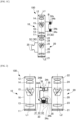
- FIGs. 1A to 1C are explanatory diagrams in planar view of the binocular system 100 according to the first embodiment. Individually, FIG. 1A shows a state that one monocular 10 and the other monocular 20 are coupled, FIG. 1B shows a state that the one monocular 10 and the other monocular 20 are separated, and FIG. 1C shows a state that the one monocular 10 and the other monocular 20 are connected and fixed in a lengthwise continuous manner.
- the binocular system 100 includes monoculars 10, 20 in pairs and a coupling portion 30 coupling the monoculars 10, 20 in pairs.
- the monoculars 10, 20 in pairs are composed of the one monocular 10 and the other monocular 20.
- the one monocular 10 and the other monocular 20 are similarly structured.
- the one monocular 10 includes a cylindrical lens barrel 16 centering around an optical axis L1, and an eye lens 14, an erecting prism 15 and an objective lens 13 are arranged inside the lens barrel 16 in order from a user side toward an object side along the optical axis L1.
- the erecting prism 15 is preferably a roof prism capable of designing the optical axis L1 in a straight line so as to make a size of the lens barrel 16 compact,
- the other monocular 20 includes a cylindrical lens barrel 26 centering around an optical axis L2, and an eye lens 24, an erecting prism 25 and an objective lens 23 are arranged inside the lens barrel 26 in order from the user side toward the object side along the optical axis L2.
- the erecting prism 25 is preferably a roof prism capable of designing the optical axis L2 in a straight line so as to make a size of the lens barrel 26 compact.
- the lens barrel 16 and the lens barrel 26 can be continuously arranged in a longitudinal direction so that the optical axis L1 and the optical axis L2 are in a straight line. Therefore, the one monocular 10 and the other monocular 20 can be connected and fixed in a lengthwise continuous manner. It is noted that the same effect can be also obtained by connecting the second connected portion 12 on the side of the eye lens 14 of the one monocular 10 to the second connecting portion 21 on the side of the objective lens 23 of the other monocular 20.
- the one monocular 10 and the other monocular 20 can be separated (see FIG. 1B ). Then, by coupling the one monocular 10 and the other monocular 20 with the coupling portion 30 from a state that the one monocular 10 and the other monocular 20 are separated, the binocular system 100 in which the optical axis L1 and the optical axis L2 are arranged in a parallel manner can be obtained (See FIG. 1A ).
- the user can use either the one monocular 10 or the other monocular 20 independently.
- the user can use them as a telescope with higher magnification (for example, 25 times) which is obtained by multiplying each magnification (for example, 5 times) in case that the one monocular 10 or the other monocular 20 is used independently, when looking at the object from the side of the eye lens 14 in a state that the one monocular 10 and the other monocular 20 are connected and fixed in a lengthwise continuous manner.
- the user can use them as a magnifier, when looking at the object from the side of the objective lens 23 in a state that the one monocular 10 and the other monocular 20 are connected and fixed in a lengthwise continuous manner.
- the coupling portion 30 has a first coupling portion 31 formed integrally with the one monocular 10, a second coupling portion 32 formed integrally with the other monocular 20, and a hinge portion 33 coupling the first coupling portion 31 and the second coupling portion 32 in such a manner that a mutual bending angle therebetween is adjustable centering around a bending axis B.
- the bending axis B is parallel to the optical axis L1 and the optical axis L2. Since the bending angle is adjustable, a distance between the optical axis L1 and the optical axis L2 can be matched with a pupil distance of the user.
- the first coupling portion 31 and the second coupling portion 32 are detachable from each other.
- the first coupling portion 31 and the second coupling portion 32 are detachable from each other, that is, the one monocular 10 and the other monocular 20 are detachable from each other, the one monocular 10 and the other monocular 20 can be separated to become respectively independent monoculars. Therefore, with one binocular system 100, two users can use respective monoculars simultaneously.
- the binocular system 100 which has the number of parts reduced and becomes lightweight and compact can be obtained.
- the first coupling portion 31 is formed integrally with the lens barrel 16 of the one monocular 10.
- the first coupling portion 31 is formed protruding in a lateral direction from an outer peripheral surface of the lens barrel 16 toward the other monocular 20.
- the first coupling portion 31 has bifurcated end portions which are in a substantially concave shape in planar view.
- the bifurcated end portions of the first coupling portion 31 are provided with shaft members 34, respectively, which function to allow the first coupling portion 31 and the second coupling portion 32 to be bendably coupled.
- the second coupling portion 32 is formed integrally with the lens barrel 26 of the other monocular 20.
- the second coupling portion 32 is formed protruding in a lateral direction from an outer peripheral surface of the lens barrel 26 toward the one monocular 10.
- the second coupling portion 32 has an end portion as shaped to be fitted between the bifurcated end portions of the first coupling portion 31, which is in a substantially convex shape in planar view.
- the hinge portion 33 has the shaft members 34 which are incorporated in the first coupling portion 31, respectively, and movable forward and backward in a direction of the bending axis B.
- Each shaft member 34 has a ball 34b engageable with an engaged portion 35 which is a recess provided in the second coupling portion 32, and an elastic body 34s which is supported in the first coupling portion 31 while energizing the ball 34b toward the second coupling portion 32 in the direction of the bending axis B.
- the second coupling portion 32 has at the end portion the engaged portions 35, 35 which are recesses engageable with the shaft members 34 provided at the bifurcated end portions of the first coupling portion 31, respectively.
- the balls 34b in pairs are energized in a direction approaching to each other by the elastic bodies 34s in pairs, a state that the balls 34b in pairs are engaged with the engaged portions 35, 35 in pairs is maintained.
- the bending angle between the first coupling portion 31 and the second coupling portion 32 can be maintained at a desired angle by friction of the balls 34b in pairs with the engaged portions 35, 35 in pairs.
- the hinge portion 33 is different as compared with the binocular system 100 according to the first embodiment, and the others are in common. So, here, the hinge portion 33 is mainly described and explanations in common may be sometimes omitted.
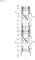
- FIG. 2 is an explanatory diagram in planar view of the binocular system 100 according to the second embodiment.
- the binocular system 100 according to the second embodiment includes the monoculars 10, 20 in pairs and the coupling portion 30 coupling the monoculars 10, 20 in pairs as well as the binocular system 100 according to the first embodiment.
- the hinge portion 33 has a shaft member 34A movable forward and backward in the direction of the bending axis B and a shaft member 34B protruding toward the shaft member 34A along the bending axis B, wherein both are incorporated in the first coupling portion 31.
- the shaft member 34A has the ball 34b engageable with the engaged portion 35 which is a recess provided in the second coupling portion 32, and the elastic body 34s which is supported in the first coupling portion 31 while energizing the ball 34b toward the second coupling portion 32 in the direction of the bending axis B.
- the shaft member 34B has a protruding portion 34t protruding toward the shaft member 34A along the bending axis B so as to be engageable with the engaged portion 35 which is a recess provided in the second coupling portion 32.
- a male screw provided on an outer periphery of the shaft member 34B is screwed into a female screw provided on the first coupling portion 31 for mutual fixation.
- the second coupling portion 32 has at the end portion the engaged portions 35, 35 which are recesses engageable with the shaft members 34A, 34B provided at the bifurcated end portions of the first coupling portion 31, respectively.
- the bending angle between the first coupling portion 31 and the second coupling portion 32 can be maintained at a desired angle by friction of the protruding portion 34t and the ball 34b with the engaged portions 35, 35 in pairs.
- the hinge portion 33 is different as compared with the binocular system 100 according to the first embodiment, and the others are in common. So, here, the hinge portion 33 is mainly described and explanations in common may be sometimes omitted.
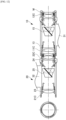
- FIG. 3 is an explanatory diagram in planar view of the binocular system 100 according to the third embodiment.
- the binocular system 100 according to the third embodiment includes the monoculars 10, 20 in pairs and the coupling portion 30 coupling the monoculars 10, 20 in pairs as well as the binocular system100 according to the first embodiment.
- the hinge portion 33 has the shaft member 34A protruding toward the shaft member 34B along the bending axis B and the shaft member 34B protruding toward the shaft member 34A along the bending axis B, wherein both are incorporated in the first coupling portion 31.
- the shaft member 34A has a shaft 34c engageable at one end with the other engaged portion 35 which is a recess provided in the second coupling portion 32, and a female screw portion 34d to be screwed to the shaft 34c for fixation to the first coupling portion 31.
- the other end of the shaft 34c is provided with a head to make it easier for the user to turn the shaft 34c.
- a stopping member is provided on the one end of the shaft 34c to prevent the shaft 34c from coming out of the female screw portion 34d.
- the shaft member 34B has the protruding portion 34t protruding toward the shaft member 34A along the bending axis B so as to be engageable with the one engaged portion 35 which is a recess provided in the second coupling portion 32.
- the second coupling portion 32 has at the end portion the engaged portions 35, 35 which are recesses engageable with the shaft members 34A, 34B provided at the bifurcated end portions of the first coupling portion 31, respectively.
- the bending angle between the first coupling portion 31 and the second coupling portion 32 can be maintained at a desired angle by friction of the protruding portion 34t and the shaft 34c with the engaged portions 35, 35 in pairs.
- the hinge portion 33 is different as compared with the binocular system 100 according to the first embodiment, and the others are in common. So, here, the hinge portion 33 is mainly described and explanations in common may be sometimes omitted.
- FIG. 4 is an explanatory diagram in planar view of the binocular system 100 according to the fourth embodiment.
- the binocular system 100 according to the fourth embodiment includes the monoculars 10, 20 in pairs and the coupling portion 30 coupling the monoculars 10, 20 in pairs as well as the binocular system 100 according to the first embodiment.
- the hinge portion 33 has the shaft member 34A protruding toward the shaft member 34B along the bending axis B and the shaft member 34B protruding toward the shaft member 34A along the bending axis B, wherein both are incorporated in the first coupling portion 31.
- the shaft member 34A has a piston 34p provided with a pin engageable at one end with the other engaged portion 35 which is a recess provided in the second coupling portion 32, and the elastic body 34s energizing the piston 34p toward the other engaged portion 35.
- the piston 34p penetrates the elastic body 34s.
- the elastic body 34s is supported in the first coupling portion 31.
- the other end of the piston 34p is provided with a knob to make it easier for the user to move reciprocally the piston 34p.
- the shaft member 34B has the protruding portion 34t protruding toward the shaft member 34A along the bending axis B so as to be engageable with the one engaged portion 35 which is a recess provided in the second coupling portion 32.
- the second coupling portion 32 has at the end portion the engaged portions 35, 35 which are recesses engageable with the shaft members 34A, 34B provided at the bifurcated end portions of the first coupling portion 31, respectively.
- the bending angle between the first coupling portion 31 and the second coupling portion 32 can be maintained at a desired angle by friction of the protruding portion 34t and the piston 34p with the engaged portions 35, 35 in pairs.
- the coupling portion 30 is different as compared with the binocular system 100 according to the first embodiment, and the others are in common. So, here, the coupling portion 30 is mainly described and explanations in common may be sometimes omitted. It is noted that the binocular system 100 according to each of the fifth embodiment to a ninth embodiment as described below shows an example in which the coupling portion 30 is detachably provided with a separating portion 40.
- FIG. 5A is an explanatory diagram in planar view of the binocular system 100 according to the fifth embodiment
- FIG. 5B is an explanatory diagram in front view of the binocular system 100 according to the fifth embodiment.
- the binocular system 100 according to the fifth embodiment includes the monoculars 10, 20 in pairs and the coupling portion 30 coupling the monoculars 10, 20 in pairs as well as the binocular system 100 according to the first embodiment.
- the coupling portion 30 has the first coupling portion 31 formed integrally with the one monocular 10, the second coupling portion 32 formed integrally with the other monocular 20, and the hinge portion 33 coupling the first coupling portion 31 and the second coupling portion 32 in such a manner that a mutual bending angle is adjustable centering around the bending axis B.
- At least one of the first coupling portion 31 and the second coupling portion 32 has the separating portion 40 as detachably provided.
- the separating portion 40 By means of the separating portion 40, the one monocular 10 and the other monocular 20 are detachable. Since at least one of the first coupling portion 31 and the second coupling portion 32 has the separating portion 40 as detachably provided, and then, both are detachable from each other in the separating portion 40, the one monocular 10 and the other monocular 20 can be separated to become respectively independent monoculars. Therefore, with the binocular system 100, two users can use respective monoculars simultaneously.
- the binocular system 100 which has the number of parts reduced and becomes lightweight and compact can be obtained.
- the first coupling portion 31 is formed integrally with the lens barrel 16 of the one monocular 10.
- the first coupling portion 31 is formed protruding in a lateral direction from the outer peripheral surface of the lens barrel 16 toward the other monocular 20.
- the first coupling portion 31 is in a substantially stairs shape in planar view.
- the first coupling portion 31 has a lens barrel side portion 31A formed integrally with the lens barrel 16 and a hinge side portion 31B detachable via the separating portion 40 with respect to the lens barrel side portion 31A.
- the second coupling portion 32 is formed integrally with the lens barrel 26 of the other monocular 20.
- the second coupling portion 32 is formed protruding in a lateral direction from the outer peripheral surface of the lens barrel 26 toward the one monocular 10.
- the second coupling portion 32 is in a substantially stairs shape by making the first coupling portion 31 inverted symmetrically in a front and back direction (symmetrically in an up and down direction in FIG. 5 ) in planar view.
- the second coupling portion 32 has a lens barrel side portion 32A formed integrally with the lens barrel 26 and a hinge side portion 32B detachable via the separating portion 40 with respect to the lens barrel side portion 32A.
- the lens barrel side portion 31A has a convex portion insertable into a concave portion provided in the hinge side portion 31B, and the hinge side portion 31B has the concave portion having a shape corresponding to a shape of the convex portion of the lens barrel side portion 31A.
- the lens barrel side portion 31A and the hinge side portion 31B are removable from each other.
- the barrel side portion 31A has an elastic slit portion 31Aq provided with tongue pieces in pairs between which an engaging pin 31Bp of the hinge side portion 31B is engageable by frictional force caused by being clamped therebetween.
- the hinge side portion 31B has the engaging pin 31Bp in a rod shape to be clamped in the elastic slit portion 31Aq. Therefore, by inserting the convex portion of the lens barrel side portion 31A into the concave portion of the hinge side portion 31B, and at the same time, by clamping the engaging pin 31Bp in the elastic slit portion 31Aq, the lens barrel side portion 31A and the hinge side portion 31B can be fixed with each other.
- the separating portion 40 may be provided on at least one of the first coupling portion 31 and the second coupling portion 32, that is, on both of the first coupling portion 31 and the second coupling portion 32, or on only one of the first coupling portion 31 and the second coupling portion 32.
- the hinge portion 33 has the shaft member 34 which is incorporated in the first coupling portion 31 and the second coupling portion 32 to be arranged along the direction of the bending axis B.
- the shaft member 34 may not be detachable with respect to the first coupling portion 31 and the second coupling portion 32, and it may be formed in a divided manner in order to simplify assembling.
- the shaft member 34 fastens the first coupling portion 31 and the second coupling portion 32.
- frictional force between the first coupling portion 31 and the second coupling portion 32 becomes adjustable. Then, the bending angle between the first coupling portion 31 and the second coupling portion 32 can be maintained at a desired angle by friction of the first coupling portion 31 with the second coupling portion 32.
- the binocular system 100 according to each of the sixth embodiment to the ninth embodiments is different as compared with the binocular system 100 according to the fifth embodiment regarding the separating portion 40, and the others are in common. So, here, the separating portion 40 is mainly described and explanations in common may be sometimes omitted. It is noted that the binocular system 100 according to each of the fifth embodiment to the ninth embodiment shows an example in which the coupling portion 30 is detachably provided with the separating portion 40.
- FIG. 6A is an explanatory diagram in planar view of the binocular system 100 according to the sixth embodiment
- FIG. 6B is an explanatory diagram in front view of the binocular system 100 according to the sixth embodiment.
- At least one of the first coupling portion 31 and the second coupling portion 32 has the separating portion 40 as detachably provided.
- both of the first coupling portion 31 and the second coupling portion 32 have the separating portions 40 as detachably provided, for example.
- the separating portions 40 the one monocular 10 and the other monocular 20 are detachable.
- the one monocular 10 and the other monocular 20 can be separated to become respectively independent monoculars. Therefore, with the binocular system 100, two users can use respective monoculars simultaneously.
- the separating portion 40 is a so-called dovetail joint in which a dovetail tenon 36 formed in the lens barrel side portion 31A is fitted into a dovetail groove 37 formed in the hinge side portion 31B. Additionally, the dovetail groove 37 may be formed in the barrel side portion 31A and the dovetail tenon 36 may be formed in the hinge side portion 31B. In the separating portion 40, one or both of the dovetail groove 37 and the dovetail tenon 36 is/are provided with a taper along a longitudinal direction. Then, when the dovetail tenon 36 is slidably fitted into the dovetail groove 37 in a front and back direction (an up and down direction in FIG.
- the dovetail groove 37 and the dovetail tenon 36 are tightened and fixed to each other.
- the lens barrel side portion 31A and the hinge side portion 31B can be separated by sliding them in a reverse direction.
- FIG. 7A is an explanatory diagram in planar view of the binocular system 100 according to the seventh embodiment
- FIG. 7B is an explanatory diagram in front view of the binocular system 100 according to the seventh embodiment.
- the first coupling portion 31 and the second coupling portion 32 has the separating portion 40 as detachably provided.
- only one of the first coupling portion 31 and the second coupling portion 32 has the separating portion 40, for example.
- the separating portion 40 the one monocular 10 and the other monocular 20 are detachable.
- the one monocular telecope10 and the other monocular 20 can be separated to become respectively independent monoculars. Therefore, with the binocular system 100, two users can use respective monoculars simultaneously.
- FIG. 8 is an explanatory diagram in front view of the binocular system 100 according to the eighth embodiment.
- At least one of the first coupling portion 31 and the second coupling portion 32 has the separating portion 40 as detachably provided.
- the separating part 40 By means of the separating part 40, the one monocular 10 and the other monocular 20 are detachable.
- the one monocular 10 and the other monocular 20 can be separated to become respectively independent monoculars. Therefore, with the binocular system 100, two users can use respective monoculars simultaneously.
- FIG. 9 is an explanatory diagram in front view of the binocular system 100 according to the ninth embodiment.
- the separation portion 40 is similar to the separation portion 40 according to the fifth embodiment and is provided in the first coupling portion 31.
- the bending axis B is set at a position eccentric from the middle between the optical axis L1 of the one monocular 10 and the optical axis L2 of the other monocular 20. More specifically, with respect to the middle between the optical axis L1 and the optical axis L2, such eccentric position is set on a side (a side of the other monocular 20) opposite to a side (a side of the one monocular 10) on which the separating portion 40 is located.
- the center of gravity can be brought closer to the middle between the optical axis L1 and the optical axis L2.
- the weight of the one monocular 10 and the weight of the other monocular 20 can become close when they are independently separated into the one monocular 10 and the other monocular 20 at the separating portion 40. Therefore, the binocular system 100 becomes better in weight balance and improved in feeling of use in either case when used as a binocular system, when used as a telescope, or when used as a monocular.
- the tenth embodiment to a twelfth embodiment as described below show specific examples of the first connecting portion 11 (a connecting portion) and the first connected portion 22 (a connected portion) when the binocular system 100 is used as a telescope.
- the lens barrel 16 and the lens barrel 26 are continuously arranged in a longitudinal direction so that the optical axis L1 and the optical axis L2 are in a straight line. Therefore, the one monocular 10 and the other monocular 20 are connected and fixed in a lengthwise continuous manner.
- the first connecting portion 11A and the first connected portion 22A are configured by a push-in joint.
- the first connecting portion 11A and the first connected portion 22A are, for example, elastic bodies made of resin.
- the first connecting portion 11A and the first connected portion 22A are formed in cylindrical shape.
- an outer diameter of the first connected portion 22A is set slightly larger than an inner diameter of the first connecting portion 11A.
- first connecting portion 11A and the first connected portion 22A can be separated.
- second connected portion 12A and the second connecting portion 21A may be similarly configured.
- a male-to-female relationship between the first connecting portion 11A and the first connected portion 22A may be reversed. In this manner, the one monocular 10 and the other monocular 20 can be connected and fixed with no looseness by user's operation and this connection can be released with ease by user's operation.
- FIG. 11 is an explanatory diagram in side view when the binocular system 100 according to the eleventh embodiment is used as a telescope.
- a first connecting portion 11B and a first connected portion 22B are configured by a screw joint.
- the first connecting portion 11B has a male screw thereon and the first connected portion 22B has a female screw thereon.
- the second connected portion 12B and the second connecting portion 21B may be similarly configured. Also, a male-to-female relationship between the first connecting portion 11B and the first connected portion 22B may be reversed.
- the second connected portion 12B may be provided with a repositionable eyecup M having a female screw screwable to a male screw of the second connected portion 12B. In this manner, the one monocular 10 and the other monocular 20 can be connected and fixed with no looseness by user's operation and this connection can be released with ease by user's operation.
- FIG. 12 is an explanatory diagram in side view when the binocular system 100 according to the twelfth embodiment is used as a telescope.
- the first connecting portion 11C and the first connected portion 22C are configured by a bayonet joint.
- the first connected portion 22C is a male side and the first connecting portion 11C is a female side. Then, by parallelly moving the first connecting portion 11C and the first connected portion 22C in a direction approaching to each other in a state that a phase of a slit on the female side of the first connecting portion 11C and a phase of a projecting portion on the male side of the first connected portion 22C are aligned, and then, by rotating them, a state that the one monocular 10 and the other monocular 20 are connected in a lengthwise continuous manner is maintained.
- first connecting portions 11C and the first connected portion 22C can be separated.
- second connected portion 12C and the second connecting portion 21C may be similarly configured.
- a male-to-female relationship between the first connecting portion 11C and the first connected portion 22C may be reversed.
- the second connected portion 12C may be provided with the repositionable eyecup M engageable with the male side of the second connected portion 12C. In this manner, the one monocular 10 and the other monocular 20 can be connected and fixed with no looseness by user's operation and this connection can be released with ease by user's operation.
- any one of the first to ninth embodiments in which the one monocular 10 and the other monocular 20 are detachably coupled
- a configuration according to any one of the tenth to twelfth embodiments in which a connecting portion is provided on the side of the objective lens 13 of the one monocular 10 and a connected portion is provided on the side of the eye lens 24 of the other monocular 20.
- the binocular system 100 of the present invention includes the monoculars 10, 20 in pairs and the coupling portion 30 of coupling the monoculars 10, 20 in pairs, wherein: the one monocular 10 has the connecting portion 11 on the side of an objective lens 13 thereof; the other monocular 20 has the connected portion 22 connectable to the connecting portion 11 on the side of the eye lens 24 thereof; the coupling portion 30 includes the first coupling portion 31 formed integrally with the one monocular 10, the second coupling portion 32 formed integrally with the other monocular 20, and the hinge portion 33 coupling the first coupling portion 31 and the second coupling portion 32 in such a manner that a mutual bending angle therebetween is adjustable centering around the bending axis B; and the one monocular 10 and the other monocular 20 are detachable from each other. Consequently, it is possible to provide the binocular system 100 which has the number of parts reduced, becomes lightweight and compact, and is also usable as a telescope.
Landscapes
- Physics & Mathematics (AREA)
- Astronomy & Astrophysics (AREA)
- General Physics & Mathematics (AREA)
- Optics & Photonics (AREA)
- Telescopes (AREA)
Description
- The present invention relates to a binocular system.
- Conventionally, known are a binocular system which includes monoculars in pairs removably received in a coupling member called a glasses body, and each monocular is provided with a connecting mechanism in which a side of an eye lens of one monocular and a side of an objective lens of the other monocular are connected (see, for example, Patent Document 1). Accordingly, the above binocular system can be used as a binocular system per se in usual, and then, if necessary, it can be used as a telescope with higher magnification by taking out the one monocular from the coupling member to connect it to the other monocular.
- However, since this conventional binocular system requires the coupling member (the glasses body) independent from the monoculars in pairs, it is excessive in the number of parts, weight and size not only when used as a binocular system but even when used as a telescope, and consequently, that there is room for improvement thereof.
- Document
DE 43 11 366 C1 discloses a binocular system according to the preamble of claim 1. Further, documentUS 2 573 560 A discloses a binocular system comprising a hinge mechanism for adjusting the interocular distance. - Patent Literature 1:
Japanese Unexamined Utility Model Application Publication No. 58-146208 - The present invention has been made in view of the above-mentioned problems, and it is an object of the present invention to provide a binocular system which has the number of parts reduced, becomes lightweight and compact, and is also usable as a telescope.
- The above object is achieved by the binocular system according to claim 1.
- In order to achieve the above object, the present invention is grasped by the following configurations.
- (1) A binocular system in accordance with an aspect of the present invention includes: monoculars in pairs; and a coupling portion coupling the monoculars in pairs, wherein: one monocular has a connecting portion on a side of an objective lens thereof; the other monocular has a connected portion connectable to the connecting portion on a side of an eye lens thereof; the coupling portion includes a first coupling portion formed integrally with the one monocular, a second coupling portion formed integrally with the other monocular, and a hinge portion coupling the first coupling portion and the second coupling portion in such a manner that a mutual bending angle therebetween is adjustable centering around a bending axis; and the one monocular and the other monocular are detachable from each other.
- (2) In the configuration of the above (1), the hinge portion may have a shaft member movable forward and backward in a direction of the bending axis.
- (3) In the above configuration (1) or (2), at least one of the first coupling portion and the second coupling portion may have a detachable separating portion.
- According to the present invention, it is possible to provide a binocular system which has the number of parts reduced, becomes lightweight and compact, and is also usable as a telescope.
-
-
FIG. 1A is an explanatory diagram in planar view of a binocular system according to a first embodiment in a state that one monocular and the other monocular are coupled. -
FIG. 1B is an explanatory diagram in planar view of the binocular system according to the first embodiment in a state that the one monocular and the other monocular are separated. -
FIG. 1C is an explanatory diagram in planar view of the binocular system according to the first embodiment in a state that the one monocular and the other monocular are connected and fixed in a lengthwise continuous manner. -
FIG. 2 is an explanatory diagram in planar view of a binocular system according to a second embodiment. -
FIG. 3 is an explanatory diagram in planar view of a binocular system according to a third embodiment. -
FIG. 4 is an explanatory diagram in planar view of a binocular system according to a fourth embodiment. -
FIG. 5A is an explanatory diagram in planar view of a binocular system according to a fifth embodiment. -
FIG. 5B is an explanatory diagram in front view of the binocular system according to the fifth embodiment. -
FIG. 6A is an explanatory diagram in planar view of a binocular system according to a sixth embodiment. -
FIG. 6B is an explanatory diagram in front view of the binocular system according to the sixth embodiment. -
FIG. 7A is an explanatory diagram in planar view of a binocular system according to a seventh embodiment. -
FIG. 7B is an explanatory diagram in front view of the binocular system according to the seventh embodiment. -
FIG. 8 is an explanatory diagram in front view of a binocular system according to an eighth embodiment. -
FIG. 9 is an explanatory diagram in front view of a binocular system according to a ninth embodiment. -
FIG. 10 is an explanatory diagram in side view when a binocular system according to a tenth embodiment is used as a telescope. -
FIG. 11 is an explanatory diagram in side view when a binocular system according to an eleventh embodiment is used as a telescope. -
FIG. 12 is an explanatory diagram in side view when a binocular system according to a twelfth embodiment is used as a telescope. - The Third and the Fifth to Twelfth Embodiments described below are not encompassed by the wording of the claims but are considered as useful for understanding the invention.
- Hereinafter, a first embodiment to carry out the present invention is described in detail with reference to the accompanying drawings. It is noted that a
binocular system 100 according to each of the first embodiment to a fourth embodiment as described below shows an example in which ahinge portion 33 is provided with ashaft member 34 movable forward and backward in a direction of a bending axis B. In the following description, unless otherwise specified, a direction that a user views an object through thebinocular system 100, namely an up and down direction inFIG. 1 , is defined as a forth and back direction. -
FIGs. 1A to 1C are explanatory diagrams in planar view of thebinocular system 100 according to the first embodiment. Individually,FIG. 1A shows a state that one monocular 10 and the other monocular 20 are coupled,FIG. 1B shows a state that the one monocular 10 and the other monocular 20 are separated, andFIG. 1C shows a state that the one monocular 10 and the other monocular 20 are connected and fixed in a lengthwise continuous manner. - As shown in
FIGs. 1A, 1B and1C , thebinocular system 100 according to the first embodiment includesmonoculars coupling portion 30 coupling themonoculars - The
monoculars cylindrical lens barrel 16 centering around an optical axis L1, and aneye lens 14, an erectingprism 15 and anobjective lens 13 are arranged inside thelens barrel 16 in order from a user side toward an object side along the optical axis L1. The erectingprism 15 is preferably a roof prism capable of designing the optical axis L1 in a straight line so as to make a size of thelens barrel 16 compact, - Similarly, the other monocular 20 includes a
cylindrical lens barrel 26 centering around an optical axis L2, and aneye lens 24, an erectingprism 25 and anobjective lens 23 are arranged inside thelens barrel 26 in order from the user side toward the object side along the optical axis L2. The erectingprism 25 is preferably a roof prism capable of designing the optical axis L2 in a straight line so as to make a size of thelens barrel 26 compact. - The one
monocular 10 of themonoculars objective lens 13, and theother monocular 20 thereof has a first connected portion 22 (a connected portion) connectable to the first connectingportion 11 on a side of theeye lens 24. Additionally, in like manner, theother monocular 20 of themonoculars portion 21 on a side of theobjective lens 23 thereof, and the onemonocular 10 may have a second connectedportion 12 connectable to the second connectingportion 21 on a side of theeye lens 14 thereof. - The first connecting
portion 11 and the first connectedportion 22 are configured by, for example, a push-in joint (seeFIG. 10 ), a screw joint (seeFIG. 11 ) or a bayonet joint (seeFIG. 12 ), so that they can be connected and fixed with no looseness by user's operation and can be released from connection with ease by user's operation. Accordingly, by separating thebinocular system 100, as shown inFIG. 1B , into the onemonocular 10 and theother monocular 20 with regard to thecoupling portion 30, and then, by connecting the first connectedportion 22 of theother monocular 20, as shown inFIG. 1C , to the first connectingportion 11 of the onemonocular 10, thelens barrel 16 and thelens barrel 26 can be continuously arranged in a longitudinal direction so that the optical axis L1 and the optical axis L2 are in a straight line. Therefore, the onemonocular 10 and theother monocular 20 can be connected and fixed in a lengthwise continuous manner. It is noted that the same effect can be also obtained by connecting the second connectedportion 12 on the side of theeye lens 14 of the onemonocular 10 to the second connectingportion 21 on the side of theobjective lens 23 of theother monocular 20. - Further, by releasing such connection of the first connecting
portion 11 and the first connectedportion 22 in a state that the onemonocular 10 and theother monocular 20 are connected and fixed in a lengthwise continuous manner (seeFIG. 1C ), the onemonocular 10 and theother monocular 20 can be separated (seeFIG. 1B ). Then, by coupling the onemonocular 10 and theother monocular 20 with thecoupling portion 30 from a state that the onemonocular 10 and theother monocular 20 are separated, thebinocular system 100 in which the optical axis L1 and the optical axis L2 are arranged in a parallel manner can be obtained (SeeFIG. 1A ). - As above, the user can use either the one
monocular 10 or theother monocular 20 independently. In addition, the user can use them as a telescope with higher magnification (for example, 25 times) which is obtained by multiplying each magnification (for example, 5 times) in case that the onemonocular 10 or theother monocular 20 is used independently, when looking at the object from the side of theeye lens 14 in a state that the onemonocular 10 and theother monocular 20 are connected and fixed in a lengthwise continuous manner. Further, the user can use them as a magnifier, when looking at the object from the side of theobjective lens 23 in a state that the onemonocular 10 and theother monocular 20 are connected and fixed in a lengthwise continuous manner. - The
coupling portion 30 has afirst coupling portion 31 formed integrally with the onemonocular 10, asecond coupling portion 32 formed integrally with theother monocular 20, and ahinge portion 33 coupling thefirst coupling portion 31 and thesecond coupling portion 32 in such a manner that a mutual bending angle therebetween is adjustable centering around a bending axis B. The bending axis B is parallel to the optical axis L1 and the optical axis L2. Since the bending angle is adjustable, a distance between the optical axis L1 and the optical axis L2 can be matched with a pupil distance of the user. Thefirst coupling portion 31 and thesecond coupling portion 32 are detachable from each other. - In this way, since the
first coupling portion 31 and thesecond coupling portion 32 are detachable from each other, that is, the onemonocular 10 and theother monocular 20 are detachable from each other, the onemonocular 10 and theother monocular 20 can be separated to become respectively independent monoculars. Therefore, with onebinocular system 100, two users can use respective monoculars simultaneously. - In addition, since the
first coupling portion 31 formed integrally with the onemonocular 10 and thesecond coupling portion 32 formed integrally with theother monocular 20 are detachable from each other, the onemonocular 10 and theother monocular 20 can be detachable from each other without requiring a coupling member independent from the monoculars in pairs as conventional. Therefore, thebinocular system 100 which has the number of parts reduced and becomes lightweight and compact can be obtained. - In detail, the
first coupling portion 31 is formed integrally with thelens barrel 16 of the onemonocular 10. Thefirst coupling portion 31 is formed protruding in a lateral direction from an outer peripheral surface of thelens barrel 16 toward theother monocular 20. Thefirst coupling portion 31 has bifurcated end portions which are in a substantially concave shape in planar view. The bifurcated end portions of thefirst coupling portion 31 are provided withshaft members 34, respectively, which function to allow thefirst coupling portion 31 and thesecond coupling portion 32 to be bendably coupled. - On the other hand, the
second coupling portion 32 is formed integrally with thelens barrel 26 of theother monocular 20. Thesecond coupling portion 32 is formed protruding in a lateral direction from an outer peripheral surface of thelens barrel 26 toward the onemonocular 10. Thesecond coupling portion 32 has an end portion as shaped to be fitted between the bifurcated end portions of thefirst coupling portion 31, which is in a substantially convex shape in planar view. - The
hinge portion 33 has theshaft members 34 which are incorporated in thefirst coupling portion 31, respectively, and movable forward and backward in a direction of the bending axis B. - Each
shaft member 34 has aball 34b engageable with an engagedportion 35 which is a recess provided in thesecond coupling portion 32, and anelastic body 34s which is supported in thefirst coupling portion 31 while energizing theball 34b toward thesecond coupling portion 32 in the direction of the bending axis B. - The
second coupling portion 32 has at the end portion the engagedportions shaft members 34 provided at the bifurcated end portions of thefirst coupling portion 31, respectively. - Then, when the
balls 34b in pairs are engaged with the engagedportions second coupling portion 32 is fitted between the bifurcated end portions of thefirst coupling portion 31, a state that thefirst coupling portion 31 and thesecond coupling portion 32 are coupled appears, that is, thebinocular system 100 which is configured by coupling the onemonocular 10 and theother monocular 20 is obtained. - Here, since the
balls 34b in pairs are energized in a direction approaching to each other by theelastic bodies 34s in pairs, a state that theballs 34b in pairs are engaged with the engagedportions first coupling portion 31 and thesecond coupling portion 32 can be maintained at a desired angle by friction of theballs 34b in pairs with the engagedportions - On the other hand, when force larger than a predetermined value is applied in a direction separating widthwise (right and left) the
first coupling portion 31 and thesecond coupling portion 32 in a state that thefirst coupling portion 31 and thesecond coupling portion 32 are coupled, theballs 34b in pairs are disengaged from the engagedportions elastic bodies 34s in pairs resulting in release of engagement. Therefore, thefirst coupling portion 31 and thesecond coupling portion 32 can be separated. - Next, a second embodiment to carry out the present invention is described in detail with reference to the accompanying drawings. In the
binocular system 100 according to the second embodiment, thehinge portion 33 is different as compared with thebinocular system 100 according to the first embodiment, and the others are in common. So, here, thehinge portion 33 is mainly described and explanations in common may be sometimes omitted. -
FIG. 2 is an explanatory diagram in planar view of thebinocular system 100 according to the second embodiment. - As shown in
FIG. 2 , thebinocular system 100 according to the second embodiment includes themonoculars coupling portion 30 coupling themonoculars binocular system 100 according to the first embodiment. - The
hinge portion 33 has ashaft member 34A movable forward and backward in the direction of the bending axis B and ashaft member 34B protruding toward theshaft member 34A along the bending axis B, wherein both are incorporated in thefirst coupling portion 31. Theshaft member 34A has theball 34b engageable with the engagedportion 35 which is a recess provided in thesecond coupling portion 32, and theelastic body 34s which is supported in thefirst coupling portion 31 while energizing theball 34b toward thesecond coupling portion 32 in the direction of the bending axis B. - The
shaft member 34B has a protrudingportion 34t protruding toward theshaft member 34A along the bending axis B so as to be engageable with the engagedportion 35 which is a recess provided in thesecond coupling portion 32. In order to simplify assembling theshaft member 34B into thefirst coupling portion 31, for example, a male screw provided on an outer periphery of theshaft member 34B is screwed into a female screw provided on thefirst coupling portion 31 for mutual fixation. - The
second coupling portion 32 has at the end portion the engagedportions shaft members first coupling portion 31, respectively. - Then, when the protruding
portion 34t of theshaft member 34B is engaged with one engagedportion 35 and theball 34b of theshaft member 34A is engaged with the other engagedportion 35 in a state that the end portion of thesecond coupling portion 32 is fitted between the bifurcated end portions of thefirst coupling portion 31, a state that thefirst coupling portion 31 and thesecond coupling portion 32 are coupled appears, that is, thebinocular system 100 which is configured by coupling the onemonocular 10 and theother monocular 20 is obtained. - Here, since the
ball 34b is energized in a direction facing toward theshaft member 34B by theelastic body 34s, a state that the protrudingportion 34t is engaged with the one engagedportion 35 and a state that theball 34b is engaged with the other engagedportion 35 are maintained, respectively. - The bending angle between the
first coupling portion 31 and thesecond coupling portion 32 can be maintained at a desired angle by friction of the protrudingportion 34t and theball 34b with the engagedportions - On the other hand, when the
second coupling portion 32 is moved shiftedly in the direction of the bending axis B with respect to thefirst coupling portion 31 against energizing force of theelastic body 34s in a state that thefirst coupling portion 31 and thesecond coupling portion 32 are coupled, the protrudingportion 34t is disengaged from the one engagedportion 35. Continuously, when thesecond coupling portion 32 is moved in a lateral direction (right and left) with respect to thefirst coupling portion 31, theball 34b is disengaged from the other engagedportion 35 resulting in release of engagement. Therefore, thefirst coupling portion 31 and thesecond coupling portion 32 can be separated. - Next, a third embodiment to carry out the present invention is described in detail with reference to the accompanying drawings. In the
binocular system 100 according to the third embodiment, thehinge portion 33 is different as compared with thebinocular system 100 according to the first embodiment, and the others are in common. So, here, thehinge portion 33 is mainly described and explanations in common may be sometimes omitted. -
FIG. 3 is an explanatory diagram in planar view of thebinocular system 100 according to the third embodiment. - As shown in
FIG. 3 , thebinocular system 100 according to the third embodiment includes themonoculars coupling portion 30 coupling themonoculars - The
hinge portion 33 has theshaft member 34A protruding toward theshaft member 34B along the bending axis B and theshaft member 34B protruding toward theshaft member 34A along the bending axis B, wherein both are incorporated in thefirst coupling portion 31. - The
shaft member 34A has ashaft 34c engageable at one end with the other engagedportion 35 which is a recess provided in thesecond coupling portion 32, and afemale screw portion 34d to be screwed to theshaft 34c for fixation to thefirst coupling portion 31. The other end of theshaft 34c is provided with a head to make it easier for the user to turn theshaft 34c. A stopping member is provided on the one end of theshaft 34c to prevent theshaft 34c from coming out of thefemale screw portion 34d. - The
shaft member 34B has the protrudingportion 34t protruding toward theshaft member 34A along the bending axis B so as to be engageable with the one engagedportion 35 which is a recess provided in thesecond coupling portion 32. - The
second coupling portion 32 has at the end portion the engagedportions shaft members first coupling portion 31, respectively. - Then, when the protruding
portion 34t of theshaft member 34B is engaged with the one engagedportion 35 and the one end of theshaft 34c of theshaft member 34A is engaged with the other engagedportion 35 in a state that the end portion of thesecond coupling portion 32 is fitted between the bifurcated end portions of thefirst coupling portion 31, a state that thefirst coupling portion 31 and thesecond coupling portion 32 are coupled appears, that is, thebinocular system 100 which is configured by coupling the onemonocular 10 and theother monocular 20 is obtained. - Here, since the
shaft 34c is screwed into a female thread of thefemale screw portion 34d fixed to thefirst coupling portion 31 to be held by friction, a state that the protrudingportion 34t is engaged with the one engagedportion 35 and a state that theshaft 34c is engaged with the other engagedportion 35 are maintained, respectively. - The bending angle between the
first coupling portion 31 and thesecond coupling portion 32 can be maintained at a desired angle by friction of the protrudingportion 34t and theshaft 34c with the engagedportions - On the other hand, when the
shaft 34c is turned in a direction disengaging theshaft 34c from thefemale screw portion 34d in a state that thefirst coupling portion 31 and thesecond coupling portion 32 are coupled, theshaft 34c is disengaged from the other engagedportion 35, and continuously, when theshaft 34c is further turned, the protrudingportion 34t is disengaged from the one engagedportion 35. In this state, when thesecond coupling portion 32 is moved in a lateral direction (left and right) with respect to thefirst coupling portion 31, thefirst coupling portion 31 and thesecond coupling portion 32 can be separated since thefirst coupling portion 31 and thesecond coupling portion 32 are not engaged with each other - Next, a fourth embodiment to carry out the present invention is described in detail with reference to the accompanying drawings. In the
binocular system 100 according to the fourth embodiment, thehinge portion 33 is different as compared with thebinocular system 100 according to the first embodiment, and the others are in common. So, here, thehinge portion 33 is mainly described and explanations in common may be sometimes omitted. -
FIG. 4 is an explanatory diagram in planar view of thebinocular system 100 according to the fourth embodiment. - As shown in
FIG. 4 , thebinocular system 100 according to the fourth embodiment includes themonoculars coupling portion 30 coupling themonoculars binocular system 100 according to the first embodiment. - The
hinge portion 33 has theshaft member 34A protruding toward theshaft member 34B along the bending axis B and theshaft member 34B protruding toward theshaft member 34A along the bending axis B, wherein both are incorporated in thefirst coupling portion 31. - The
shaft member 34A has apiston 34p provided with a pin engageable at one end with the other engagedportion 35 which is a recess provided in thesecond coupling portion 32, and theelastic body 34s energizing thepiston 34p toward the other engagedportion 35. Thepiston 34p penetrates theelastic body 34s. Theelastic body 34s is supported in thefirst coupling portion 31. The other end of thepiston 34p is provided with a knob to make it easier for the user to move reciprocally thepiston 34p. - The
shaft member 34B has the protrudingportion 34t protruding toward theshaft member 34A along the bending axis B so as to be engageable with the one engagedportion 35 which is a recess provided in thesecond coupling portion 32. - The
second coupling portion 32 has at the end portion the engagedportions shaft members first coupling portion 31, respectively. - Then, when the protruding
portion 34t of theshaft member 34B is engaged with the one engagedportion 35 and the one end of thepiston 34p of theshaft member 34A is engaged with the other engagedportion 35 in a state that the end portion of thesecond coupling portion 32 is fitted between the bifurcated end portions of thefirst coupling portion 31, a state that thefirst coupling portion 31 and thesecond coupling portion 32 are coupled appears, that is, thebinocular system 100 which is configured by coupling the onemonocular 10 and theother monocular 20 is obtained. - Here, since the
piston 34p is energized by theelastic body 34s which is supported in the first connectingportion 31, a state that the protrudingportion 34t is engaged with the one engagedportion 35 and a state that thepiston 34p is engaged with the other engagedportion 35 are maintained, respectively. - The bending angle between the
first coupling portion 31 and thesecond coupling portion 32 can be maintained at a desired angle by friction of the protrudingportion 34t and thepiston 34p with the engagedportions - On the other hand, when the knob is pulled in a direction separating the
piston 34p from thefirst coupling portion 31 in a state that thefirst coupling portion 31 and thesecond coupling portion 32 are coupled, the pin at the one end of thepiston 34p is disengaged from the other engagedportion 35, and continuously, when the knob is further pulled, the protrudingportion 34t is disengaged from the one engagedportion 35. In this state, when thesecond coupling portion 32 is moved in a lateral direction (left and right) with respect to thefirst coupling portion 31, thefirst coupling portion 31 and thesecond coupling portion 32 can be separated since thefirst coupling portion 31 and thesecond coupling portion 32 are not engaged with each other. - Next, a fifth embodiment to carry out the present invention is described in detail with reference to the accompanying drawings. In the
binocular system 100 according to the fifth embodiment, thecoupling portion 30 is different as compared with thebinocular system 100 according to the first embodiment, and the others are in common. So, here, thecoupling portion 30 is mainly described and explanations in common may be sometimes omitted. It is noted that thebinocular system 100 according to each of the fifth embodiment to a ninth embodiment as described below shows an example in which thecoupling portion 30 is detachably provided with a separatingportion 40. -
FIG. 5A is an explanatory diagram in planar view of thebinocular system 100 according to the fifth embodiment, andFIG. 5B is an explanatory diagram in front view of thebinocular system 100 according to the fifth embodiment. - As shown in
FIGs. 5A and 5B , thebinocular system 100 according to the fifth embodiment includes themonoculars coupling portion 30 coupling themonoculars binocular system 100 according to the first embodiment. - The
coupling portion 30 has thefirst coupling portion 31 formed integrally with the onemonocular 10, thesecond coupling portion 32 formed integrally with theother monocular 20, and thehinge portion 33 coupling thefirst coupling portion 31 and thesecond coupling portion 32 in such a manner that a mutual bending angle is adjustable centering around the bending axis B. - Here, at least one of the
first coupling portion 31 and thesecond coupling portion 32 has the separatingportion 40 as detachably provided. By means of the separatingportion 40, the onemonocular 10 and theother monocular 20 are detachable. Since at least one of thefirst coupling portion 31 and thesecond coupling portion 32 has the separatingportion 40 as detachably provided, and then, both are detachable from each other in the separatingportion 40, the onemonocular 10 and theother monocular 20 can be separated to become respectively independent monoculars. Therefore, with thebinocular system 100, two users can use respective monoculars simultaneously. - In addition, since the at least one of the
first coupling portion 31 formed integrally with the onemonocular 10 and thesecond coupling portion 32 formed integrally with theother monocular 20 has the separatingportion 40, the onemonocular 10 and theother monocular 20 can be detachable from each other without requiring a coupling member independent from the monoculars in pairs as conventional. Therefore, thebinocular system 100 which has the number of parts reduced and becomes lightweight and compact can be obtained. - In detail, the
first coupling portion 31 is formed integrally with thelens barrel 16 of the onemonocular 10. Thefirst coupling portion 31 is formed protruding in a lateral direction from the outer peripheral surface of thelens barrel 16 toward theother monocular 20. Thefirst coupling portion 31 is in a substantially stairs shape in planar view. Thefirst coupling portion 31 has a lensbarrel side portion 31A formed integrally with thelens barrel 16 and ahinge side portion 31B detachable via the separatingportion 40 with respect to the lensbarrel side portion 31A. - Similarly, the
second coupling portion 32 is formed integrally with thelens barrel 26 of theother monocular 20. Thesecond coupling portion 32 is formed protruding in a lateral direction from the outer peripheral surface of thelens barrel 26 toward the onemonocular 10. Thesecond coupling portion 32 is in a substantially stairs shape by making thefirst coupling portion 31 inverted symmetrically in a front and back direction (symmetrically in an up and down direction inFIG. 5 ) in planar view. Thesecond coupling portion 32 has a lensbarrel side portion 32A formed integrally with thelens barrel 26 and ahinge side portion 32B detachable via the separatingportion 40 with respect to the lensbarrel side portion 32A. - Since the separating
portion 40 of thefirst coupling portion 31 and the separatingportion 40 of thesecond coupling portion 32 are almost similarly structured, the separatingportion 40 of thefirst coupling portion 31 is described in detail on behalf. The lensbarrel side portion 31A has a convex portion insertable into a concave portion provided in thehinge side portion 31B, and thehinge side portion 31B has the concave portion having a shape corresponding to a shape of the convex portion of the lensbarrel side portion 31A. The lensbarrel side portion 31A and thehinge side portion 31B are removable from each other. Thebarrel side portion 31A has an elastic slit portion 31Aq provided with tongue pieces in pairs between which an engaging pin 31Bp of thehinge side portion 31B is engageable by frictional force caused by being clamped therebetween. On the other hand, thehinge side portion 31B has the engaging pin 31Bp in a rod shape to be clamped in the elastic slit portion 31Aq. Therefore, by inserting the convex portion of the lensbarrel side portion 31A into the concave portion of thehinge side portion 31B, and at the same time, by clamping the engaging pin 31Bp in the elastic slit portion 31Aq, the lensbarrel side portion 31A and thehinge side portion 31B can be fixed with each other. In addition, by removing the engaging pin 31Bp from the elastic slit portion 31Aq, they can be separated from each other. Additionally, the separatingportion 40 may be provided on at least one of thefirst coupling portion 31 and thesecond coupling portion 32, that is, on both of thefirst coupling portion 31 and thesecond coupling portion 32, or on only one of thefirst coupling portion 31 and thesecond coupling portion 32. - The
hinge portion 33 has theshaft member 34 which is incorporated in thefirst coupling portion 31 and thesecond coupling portion 32 to be arranged along the direction of the bending axis B. Theshaft member 34 may not be detachable with respect to thefirst coupling portion 31 and thesecond coupling portion 32, and it may be formed in a divided manner in order to simplify assembling. - The
shaft member 34 fastens thefirst coupling portion 31 and thesecond coupling portion 32. In addition, by adjusting fastening force of theshaft member 34, frictional force between thefirst coupling portion 31 and thesecond coupling portion 32 becomes adjustable. Then, the bending angle between thefirst coupling portion 31 and thesecond coupling portion 32 can be maintained at a desired angle by friction of thefirst coupling portion 31 with thesecond coupling portion 32. - Next, a sixth embodiment to carry out the present invention is described in detail with reference to the accompanying drawings. The
binocular system 100 according to each of the sixth embodiment to the ninth embodiments is different as compared with thebinocular system 100 according to the fifth embodiment regarding the separatingportion 40, and the others are in common. So, here, the separatingportion 40 is mainly described and explanations in common may be sometimes omitted. It is noted that thebinocular system 100 according to each of the fifth embodiment to the ninth embodiment shows an example in which thecoupling portion 30 is detachably provided with the separatingportion 40. -
FIG. 6A is an explanatory diagram in planar view of thebinocular system 100 according to the sixth embodiment, andFIG. 6B is an explanatory diagram in front view of thebinocular system 100 according to the sixth embodiment. - As shown in
FIGs. 6A and 6B , at least one of thefirst coupling portion 31 and thesecond coupling portion 32 has the separatingportion 40 as detachably provided. Here, both of thefirst coupling portion 31 and thesecond coupling portion 32 have the separatingportions 40 as detachably provided, for example. By means of the separatingportions 40, the onemonocular 10 and theother monocular 20 are detachable. In this way, since at least one of thefirst coupling portion 31 and thesecond coupling portion 32 has the separatingportion 40 as detachably provided, and then, both are detachable from each other in the separatingportion 40, the onemonocular 10 and theother monocular 20 can be separated to become respectively independent monoculars. Therefore, with thebinocular system 100, two users can use respective monoculars simultaneously. - In detail, the separating
portion 40 is a so-called dovetail joint in which adovetail tenon 36 formed in the lensbarrel side portion 31A is fitted into adovetail groove 37 formed in thehinge side portion 31B. Additionally, thedovetail groove 37 may be formed in thebarrel side portion 31A and thedovetail tenon 36 may be formed in thehinge side portion 31B. In the separatingportion 40, one or both of thedovetail groove 37 and thedovetail tenon 36 is/are provided with a taper along a longitudinal direction. Then, when thedovetail tenon 36 is slidably fitted into thedovetail groove 37 in a front and back direction (an up and down direction inFIG. 6 ) from a state that the lensbarrel side portion 31A and thehinge side portion 31B are separated, thedovetail groove 37 and thedovetail tenon 36 are tightened and fixed to each other. The lensbarrel side portion 31A and thehinge side portion 31B can be separated by sliding them in a reverse direction. - Next, a seventh embodiment to carry out the present invention is described in detail with reference to the accompanying drawings.
-
FIG. 7A is an explanatory diagram in planar view of thebinocular system 100 according to the seventh embodiment, andFIG. 7B is an explanatory diagram in front view of thebinocular system 100 according to the seventh embodiment. - As shown in
FIGs. 7A and 7B , at least one of thefirst coupling portion 31 and thesecond coupling portion 32 has the separatingportion 40 as detachably provided. Here, only one of thefirst coupling portion 31 and thesecond coupling portion 32 has the separatingportion 40, for example. By means of the separatingportion 40, the onemonocular 10 and theother monocular 20 are detachable. In this way, since at least one of thefirst coupling portion 31 and thesecond coupling portion 32 has the separatingpart 40 as detachably provided, and then, both are detachable from each other in the separatingportion 40, the one monocular telecope10 and theother monocular 20 can be separated to become respectively independent monoculars. Therefore, with thebinocular system 100, two users can use respective monoculars simultaneously. - Next, an eighth embodiment to carry out the present invention is described in detail with reference to the accompanying drawings.
-
FIG. 8 is an explanatory diagram in front view of thebinocular system 100 according to the eighth embodiment. - As shown in
FIG. 8 , at least one of thefirst coupling portion 31 and thesecond coupling portion 32 has the separatingportion 40 as detachably provided. By means of the separatingpart 40, the onemonocular 10 and theother monocular 20 are detachable. In this way, since at least one of thefirst coupling portion 31 and thesecond coupling portion 32 has the separatingportion 40 as detachably provided, and then, both are detachable from each other in the separatingportion 40, the onemonocular 10 and theother monocular 20 can be separated to become respectively independent monoculars. Therefore, with thebinocular system 100, two users can use respective monoculars simultaneously. - Next, the ninth embodiment to carry out the present invention is described in detail with reference to the accompanying drawings.
-
FIG. 9 is an explanatory diagram in front view of thebinocular system 100 according to the ninth embodiment. - As shown in
FIG. 9 , theseparation portion 40 is similar to theseparation portion 40 according to the fifth embodiment and is provided in thefirst coupling portion 31. The bending axis B is set at a position eccentric from the middle between the optical axis L1 of the onemonocular 10 and the optical axis L2 of theother monocular 20. More specifically, with respect to the middle between the optical axis L1 and the optical axis L2, such eccentric position is set on a side (a side of the other monocular 20) opposite to a side (a side of the one monocular 10) on which the separatingportion 40 is located. As a result, as compared with a case where the bending axis B is set on the middle between the optical axis L1 and the optical axis L2, the center of gravity can be brought closer to the middle between the optical axis L1 and the optical axis L2. Also, the weight of the onemonocular 10 and the weight of theother monocular 20 can become close when they are independently separated into the onemonocular 10 and theother monocular 20 at the separatingportion 40. Therefore, thebinocular system 100 becomes better in weight balance and improved in feeling of use in either case when used as a binocular system, when used as a telescope, or when used as a monocular. - Next, a tenth embodiment to carry out the present invention is described in detail with reference to the accompanying drawings. The tenth embodiment to a twelfth embodiment as described below show specific examples of the first connecting portion 11 (a connecting portion) and the first connected portion 22 (a connected portion) when the
binocular system 100 is used as a telescope. -
FIG. 10 is an explanatory diagram in side view when thebinocular system 100 according to the tenth embodiment is used as a telescope. As shown inFIG. 1C , the onemonocular 10 has a first connectingportion 11A (a connecting portion) on the side of theobjective lens 13, and theother monocular 20 has a firstconnected portion 22A (a connected portion) connectable to the first connectingportion 11A on the side of theeye lens 24. Additionally, the onemonocular 10 may have a secondconnected portion 12A (a connected portion) on the side of theeye lens 14, and theother monocular 20 may have a second connectingportion 21A (a connecting portion) connectable to the secondconnected portion 12A on the side of theobjective lens 23. Then, by connecting the firstconnected portion 22A of theother monocular 20 to the first connectingportion 11A of the onemonocular 10, thelens barrel 16 and thelens barrel 26 are continuously arranged in a longitudinal direction so that the optical axis L1 and the optical axis L2 are in a straight line. Therefore, the onemonocular 10 and theother monocular 20 are connected and fixed in a lengthwise continuous manner. - Here, as shown in
FIG. 10 , the first connectingportion 11A and the firstconnected portion 22A are configured by a push-in joint. Specifically, the first connectingportion 11A and the firstconnected portion 22A are, for example, elastic bodies made of resin. The first connectingportion 11A and the firstconnected portion 22A are formed in cylindrical shape. In addition, an outer diameter of the firstconnected portion 22A is set slightly larger than an inner diameter of the first connectingportion 11A. By inserting the firstconnected portion 22A into the first connectingportion 11A to be fitted in a mutually tightened state, a state that the onemonocular 10 and theother monocular 20 are connected in a lengthwise continuous manner is maintained. Further, when force larger than a predetermined value is applied in a direction separating the first connectingportion 11A and the firstconnected portion 22A from each other, the first connectingportion 11A and the firstconnected portion 22A can be separated. Additionally, the secondconnected portion 12A and the second connectingportion 21A may be similarly configured. Also, a male-to-female relationship between the first connectingportion 11A and the firstconnected portion 22A may be reversed. In this manner, the onemonocular 10 and theother monocular 20 can be connected and fixed with no looseness by user's operation and this connection can be released with ease by user's operation. - Next, an eleventh embodiment to carry out the present invention is described in detail with reference to the accompanying drawings.
-
FIG. 11 is an explanatory diagram in side view when thebinocular system 100 according to the eleventh embodiment is used as a telescope. - As shown in
FIG. 11 , unlike the tenth embodiment, a first connectingportion 11B and a firstconnected portion 22B are configured by a screw joint. Specifically, for example, the first connectingportion 11B has a male screw thereon and the firstconnected portion 22B has a female screw thereon. By screwing the male screw of the firstconnected portion 22B in a right direction into the female screw of the first connectingportion 11B to be fixed in a mutually screwed state, a state that the onemonocular 10 and theother monocular 20 are connected in a lengthwise continuous manner is maintained. Further, when the firstconnected portion 22B is turned in a reverse direction with respect to the first connectingportion 11B, the first connectingportion 11B and the firstconnected portion 22B can be separated. Additionally, the secondconnected portion 12B and the second connectingportion 21B may be similarly configured. Also, a male-to-female relationship between the first connectingportion 11B and the firstconnected portion 22B may be reversed. The secondconnected portion 12B may be provided with a repositionable eyecup M having a female screw screwable to a male screw of the secondconnected portion 12B. In this manner, the onemonocular 10 and theother monocular 20 can be connected and fixed with no looseness by user's operation and this connection can be released with ease by user's operation. - Next, the twelfth embodiment to carry out the present invention is described in detail with reference to the accompanying drawings.
-
FIG. 12 is an explanatory diagram in side view when thebinocular system 100 according to the twelfth embodiment is used as a telescope. - As shown in
FIG. 12 , unlike the tenth embodiment and the eleventh embodiment, the first connectingportion 11C and the firstconnected portion 22C are configured by a bayonet joint. Specifically, for example, the firstconnected portion 22C is a male side and the first connectingportion 11C is a female side. Then, by parallelly moving the first connectingportion 11C and the firstconnected portion 22C in a direction approaching to each other in a state that a phase of a slit on the female side of the first connectingportion 11C and a phase of a projecting portion on the male side of the firstconnected portion 22C are aligned, and then, by rotating them, a state that the onemonocular 10 and theother monocular 20 are connected in a lengthwise continuous manner is maintained. Further, when the firstconnected portion 22C is rotated in a reverse direction with respect to the first connectingportion 11C, and then, the first connectingportion 11C and the firstconnected portion 22C are parallelly moved apart from each other, the first connectingportions 11C and the firstconnected portion 22C can be separated. Additionally, the secondconnected portion 12C and the second connectingportion 21C may be similarly configured. Also, a male-to-female relationship between the first connectingportion 11C and the firstconnected portion 22C may be reversed. The secondconnected portion 12C may be provided with the repositionable eyecup M engageable with the male side of the secondconnected portion 12C. In this manner, the onemonocular 10 and theother monocular 20 can be connected and fixed with no looseness by user's operation and this connection can be released with ease by user's operation. - Although the present invention has been described with reference to the embodiments as above, it is needless to say that the technical scope of the present invention is not limited to the scope described in the above embodiments. It is obvious to those skilled in the art that various modifications or improvements can be added to the above embodiments. Further, it is obvious from the features described in the claims that any embodiment in which such modifications or improvements are added can also be included in the technical scope of the present invention. For example, it is possible to combine appropriately a configuration according to any one of the first to ninth embodiments, in which the one
monocular 10 and theother monocular 20 are detachably coupled, and a configuration according to any one of the tenth to twelfth embodiments, in which a connecting portion is provided on the side of theobjective lens 13 of the onemonocular 10 and a connected portion is provided on the side of theeye lens 24 of theother monocular 20. - The
binocular system 100 of the present invention includes themonoculars coupling portion 30 of coupling themonoculars monocular 10 has the connectingportion 11 on the side of anobjective lens 13 thereof; theother monocular 20 has the connectedportion 22 connectable to the connectingportion 11 on the side of theeye lens 24 thereof; thecoupling portion 30 includes thefirst coupling portion 31 formed integrally with the onemonocular 10, thesecond coupling portion 32 formed integrally with theother monocular 20, and thehinge portion 33 coupling thefirst coupling portion 31 and thesecond coupling portion 32 in such a manner that a mutual bending angle therebetween is adjustable centering around the bending axis B; and the onemonocular 10 and theother monocular 20 are detachable from each other. Consequently, it is possible to provide thebinocular system 100 which has the number of parts reduced, becomes lightweight and compact, and is also usable as a telescope. -
- 10: one monocular
- 11: first connecting portion (connecting portion)
- 11A: first connecting portion
- 11B: first connecting portion
- 11C: first connecting portion
- 12: second connected portion
- 12A: second connected portion
- 12B: second connected portion
- 12C: second connected portion
- 13: objective lens
- 14: eye lens
- 15: erecting prism
- 16: lens barrel
- 20: the other monocular
- 21: second connecting portion
- 21A: second connecting portion
- 21B: second connecting portion
- 21C: second connecting portion
- 22: first connected portion (connected portion)
- 22A: first connected portion
- 22B: first connected portion
- 22C: first connected portion
- 23: objective lens
- 24: eye lens
- 25: erecting prism
- 26: lens barrel
- 30: coupling portion
- 31: first coupling portion
- 31A: lens barrel side portion
- 31Aq: elastic slit portion
- 31B: hinge side portion
- 31Bp: engaging pin
- 32: second coupling portion
- 32A: lens barrel side portion
- 32B: hinge side portion
- 33: hinge portion
- 34: shaft member
- 34A: shaft member
- 34b: ball
- 34B: shaft member
- 34c: shaft
- 34d: female screw portion
- 34p: piston
- 34s: elastic body
- 34t: protruding portion
- 35: engaged portion
- 36: dovetail tenon
- 37: dovetail groove
- 40: separating portion
- 100: binocular system
- B: bending axis
- L1: optical axis
- L2: optical axis
- M: eyecup
Claims (5)
- A binocular system comprising:monoculars (10, 20) in pairs; anda coupling portion (30) coupling the monoculars in pairs,wherein:one monocular (10) has a connecting portion (11) on a side of an objective lens thereof;the other monocular (20) has a connected portion (22) connectable to the connecting portion (11) on a side of an eye lens thereof;the coupling portion (30) includes a first coupling portion (31) formed integrally with the one monocular (10), a second coupling portion (32) formed integrally with the other monocular (20), and a hinge portion (33) coupling the first coupling portion (31) and the second coupling portion (32) in such a manner that a mutual bending angle therebetween is adjustable centering around a bending axis (B);the one monocular (10) and the other monocular (20) are detachable from each other;the hinge portion (33) has at least one shaft member (34) movable forward and backward in a direction of the bending axis;one of the first coupling portion (31) and the second coupling portion (32) has the at least one shaft member (34);the other one of the first coupling portion (31) and the second coupling portion (32) has at least one engaged portion (35) which is a recess engageable with the at least one shaft member (34);characterized in thatthe at least one shaft member (34) comprises: either a ball (34b) engageable with the at least one engaged portion (35) or a piston (34p) provided with a pin engageable with the at least one engaged portion (35) at one end of the piston (34p); and at least one elastic body (34s) energizing the ball (34b) or the piston (34p) toward the at least one engaged portion (35) in the direction of the bending axis (B).
- The binocular system according to claim 1,
wherein the at least one shaft member (34) that comprises the piston (34p) is provided with a knob at the other end of the piston (34p) for reciprocally moving the piston in the direction of the bending axis (B). - The binocular system according to claim 1,wherein the one of the first coupling portion (31) and the second coupling portion (32) has bifurcated end portions forming a concave portion, andwherein the other one of the first coupling portion (31) and the second coupling portion (32) has a convex shaped end portion as shaped to be fitted between the bifurcated end portions of the one of the first coupling portion (31) and the second coupling portion (32), the recess being formed at the convex shaped end portion.
- The binocular system according to claim 3,wherein the hinge portion (33) includes a pair of the shaft members (34) respectively provided at the bifurcated end portions, andwherein the other one of the first coupling portion (31) and the second coupling portion (32) has a pair of the recesses respectively engageable with the shaft members (34).
- The binocular system according to any one of claims 1 to 4,
wherein the at least one shaft member (34) is provided to extend on the bending axis (B).
Applications Claiming Priority (1)
| Application Number | Priority Date | Filing Date | Title |
|---|---|---|---|
| JP2017199435A JP6439090B1 (en) | 2017-10-13 | 2017-10-13 | binoculars |
Publications (2)
| Publication Number | Publication Date |
|---|---|
| EP3477357A1 EP3477357A1 (en) | 2019-05-01 |
| EP3477357B1 true EP3477357B1 (en) | 2024-09-11 |
Family
ID=63840653
Family Applications (1)
| Application Number | Title | Priority Date | Filing Date |
|---|---|---|---|
| EP18200017.4A Active EP3477357B1 (en) | 2017-10-13 | 2018-10-12 | Binocular system |
Country Status (3)
| Country | Link |
|---|---|
| US (1) | US10852525B2 (en) |
| EP (1) | EP3477357B1 (en) |
| JP (1) | JP6439090B1 (en) |
Families Citing this family (2)
| Publication number | Priority date | Publication date | Assignee | Title |
|---|---|---|---|---|
| US12264971B2 (en) | 2021-03-09 | 2025-04-01 | Welch Allyn, Inc. | Noncontact thermometer |
| KR102946527B1 (en) * | 2025-05-13 | 2026-04-01 | 김우원 | Binoculars with constant central axis and folding force and enhanced water resistance |
Family Cites Families (11)
| Publication number | Priority date | Publication date | Assignee | Title |
|---|---|---|---|---|
| GB581578A (en) | 1944-02-12 | 1946-10-17 | Barr & Stroud Ltd | Improvements in binocular observation instruments |
| JPS58146208U (en) * | 1982-03-29 | 1983-10-01 | 柿沼 実 | binoculars |
| US5305141A (en) * | 1988-04-26 | 1994-04-19 | Asahi Kogaku Kogyo Kabushiki Kaisha | Binocular including a preassembled focusing unit |
| DE4244161A1 (en) * | 1991-12-26 | 1993-07-01 | Asahi Optical Co Ltd | Automatic focus field glasses - have lens which can be moved in direction of optical axis for sharp adjustment and lenses movable along optical axis for varying refractory force |
| DE4311366C1 (en) * | 1993-04-06 | 1994-02-10 | Juergen Dipl Ing Rinn | Binoculars convertible into telescopic with greater magnification - are adjusted by central drive whose slide is fixed to one lens tube |
| US5640271A (en) * | 1994-07-21 | 1997-06-17 | Minolta Co., Ltd. | Self-housing binocular |
| US6172808B1 (en) * | 1994-08-25 | 2001-01-09 | Philip C. Foreman | Hands-free binoculars assembly |
| JP4244371B2 (en) * | 2000-08-30 | 2009-03-25 | フジノン株式会社 | Tripod adapter |
| US20050122581A1 (en) * | 2001-04-27 | 2005-06-09 | Dirk Luthardt | Binoculars, particularly pocket binoculars |
| JP3126734U (en) * | 2006-07-20 | 2006-11-09 | 有限会社エーワン企画 | Binoculars using ball joints |
| KR101959579B1 (en) * | 2010-12-01 | 2019-03-18 | 아드렌스 비콘 인코포레이티드 | Variable binocular loupe utilizing fluid filled lens technology |
-
2017
- 2017-10-13 JP JP2017199435A patent/JP6439090B1/en active Active
-
2018
- 2018-10-03 US US16/151,065 patent/US10852525B2/en active Active
- 2018-10-12 EP EP18200017.4A patent/EP3477357B1/en active Active
Also Published As
| Publication number | Publication date |
|---|---|
| JP6439090B1 (en) | 2018-12-19 |
| US20190113737A1 (en) | 2019-04-18 |
| JP2019074590A (en) | 2019-05-16 |
| EP3477357A1 (en) | 2019-05-01 |
| US10852525B2 (en) | 2020-12-01 |
Similar Documents
| Publication | Publication Date | Title |
|---|---|---|
| JP5032332B2 (en) | Binocular loupe | |
| US9624958B2 (en) | Adaptor for connecting an electronic device having a camera to an optical device | |
| US10852525B2 (en) | Binocular system | |
| US4488790A (en) | Binocular and spectacle-type mounting assembly therefor | |
| US10330438B2 (en) | Rifle scope with adjusting aid | |
| TWI426312B (en) | Collimated optical system and method of manufacturing collimated optical system | |
| US7125126B2 (en) | Eye cup adjustment device for optical apparatus such as binoculars | |
| US10345573B2 (en) | Lens barrel and loupe | |
| US20180196268A1 (en) | Adjustable Video Headset | |
| US20150355479A1 (en) | Spectacle frame having telescopic hinges with an adjustable offset spring, mounted in a rotary end piece | |
| US20200355906A1 (en) | Optical instrument, binoculars, eyecup structure, method for moving eyecup member | |
| US20150073219A1 (en) | Stereoscopic endoscope | |
| US4892384A (en) | Binocular magnifier | |
| US9459441B2 (en) | Long-range optical apparatus including binoculars | |
| US10416435B2 (en) | Binocular eyepiece assembly and binocular telescope | |
| CN201368936Y (en) | Telescope binocular device | |
| US1210038A (en) | Eyeglasses. | |
| JP4796864B2 (en) | Shading device | |
| JP2005309095A (en) | Binoculars | |
| US1067532A (en) | Double telescope. | |
| CN202305990U (en) | Binocular | |
| KR100389718B1 (en) | Structure for settling zoom ring and focus ring for LCD projector | |
| CN208060836U (en) | A kind of binoculars objective tube | |
| US6323997B1 (en) | Binocular with adjustable bodies | |
| JP4745683B2 (en) | Magnifier |
Legal Events
| Date | Code | Title | Description |
|---|---|---|---|
| PUAI | Public reference made under article 153(3) epc to a published international application that has entered the european phase |
Free format text: ORIGINAL CODE: 0009012 |
|
| STAA | Information on the status of an ep patent application or granted ep patent |
Free format text: STATUS: REQUEST FOR EXAMINATION WAS MADE |
|
| 17P | Request for examination filed |
Effective date: 20181109 |
|
| AK | Designated contracting states |
Kind code of ref document: A1 Designated state(s): AL AT BE BG CH CY CZ DE DK EE ES FI FR GB GR HR HU IE IS IT LI LT LU LV MC MK MT NL NO PL PT RO RS SE SI SK SM TR |
|
| AX | Request for extension of the european patent |
Extension state: BA ME |
|
| RBV | Designated contracting states (corrected) |
Designated state(s): AL AT BE BG CH CY CZ DE DK EE ES FI FR GB GR HR HU IE IS IT LI LT LU LV MC MK MT NL NO PL PT RO RS SE SI SK SM TR |
|
| STAA | Information on the status of an ep patent application or granted ep patent |
Free format text: STATUS: EXAMINATION IS IN PROGRESS |
|
| 17Q | First examination report despatched |
Effective date: 20211013 |
|
| GRAP | Despatch of communication of intention to grant a patent |
Free format text: ORIGINAL CODE: EPIDOSNIGR1 |
|
| STAA | Information on the status of an ep patent application or granted ep patent |
Free format text: STATUS: GRANT OF PATENT IS INTENDED |
|
| INTG | Intention to grant announced |
Effective date: 20240527 |
|
| GRAS | Grant fee paid |
Free format text: ORIGINAL CODE: EPIDOSNIGR3 |
|
| GRAA | (expected) grant |
Free format text: ORIGINAL CODE: 0009210 |
|
| STAA | Information on the status of an ep patent application or granted ep patent |
Free format text: STATUS: THE PATENT HAS BEEN GRANTED |
|
| AK | Designated contracting states |
Kind code of ref document: B1 Designated state(s): AL AT BE BG CH CY CZ DE DK EE ES FI FR GB GR HR HU IE IS IT LI LT LU LV MC MK MT NL NO PL PT RO RS SE SI SK SM TR |
|
| REG | Reference to a national code |
Ref country code: GB Ref legal event code: FG4D |
|
| REG | Reference to a national code |
Ref country code: CH Ref legal event code: EP |
|
| REG | Reference to a national code |
Ref country code: DE Ref legal event code: R096 Ref document number: 602018074196 Country of ref document: DE |
|
| REG | Reference to a national code |
Ref country code: IE Ref legal event code: FG4D |
|
| REG | Reference to a national code |
Ref country code: LT Ref legal event code: MG9D |
|
| PG25 | Lapsed in a contracting state [announced via postgrant information from national office to epo] |
Ref country code: NO Free format text: LAPSE BECAUSE OF FAILURE TO SUBMIT A TRANSLATION OF THE DESCRIPTION OR TO PAY THE FEE WITHIN THE PRESCRIBED TIME-LIMIT Effective date: 20241211 |
|
| REG | Reference to a national code |
Ref country code: NL Ref legal event code: MP Effective date: 20240911 |
|
| PG25 | Lapsed in a contracting state [announced via postgrant information from national office to epo] |
Ref country code: GR Free format text: LAPSE BECAUSE OF FAILURE TO SUBMIT A TRANSLATION OF THE DESCRIPTION OR TO PAY THE FEE WITHIN THE PRESCRIBED TIME-LIMIT Effective date: 20241212 Ref country code: FI Free format text: LAPSE BECAUSE OF FAILURE TO SUBMIT A TRANSLATION OF THE DESCRIPTION OR TO PAY THE FEE WITHIN THE PRESCRIBED TIME-LIMIT Effective date: 20240911 |
|
| PG25 | Lapsed in a contracting state [announced via postgrant information from national office to epo] |
Ref country code: BG Free format text: LAPSE BECAUSE OF FAILURE TO SUBMIT A TRANSLATION OF THE DESCRIPTION OR TO PAY THE FEE WITHIN THE PRESCRIBED TIME-LIMIT Effective date: 20240911 |
|
| PG25 | Lapsed in a contracting state [announced via postgrant information from national office to epo] |
Ref country code: LV Free format text: LAPSE BECAUSE OF FAILURE TO SUBMIT A TRANSLATION OF THE DESCRIPTION OR TO PAY THE FEE WITHIN THE PRESCRIBED TIME-LIMIT Effective date: 20240911 |
|
| PG25 | Lapsed in a contracting state [announced via postgrant information from national office to epo] |
Ref country code: HR Free format text: LAPSE BECAUSE OF FAILURE TO SUBMIT A TRANSLATION OF THE DESCRIPTION OR TO PAY THE FEE WITHIN THE PRESCRIBED TIME-LIMIT Effective date: 20240911 |
|
| PG25 | Lapsed in a contracting state [announced via postgrant information from national office to epo] |
Ref country code: RS Free format text: LAPSE BECAUSE OF FAILURE TO SUBMIT A TRANSLATION OF THE DESCRIPTION OR TO PAY THE FEE WITHIN THE PRESCRIBED TIME-LIMIT Effective date: 20241211 Ref country code: ES Free format text: LAPSE BECAUSE OF FAILURE TO SUBMIT A TRANSLATION OF THE DESCRIPTION OR TO PAY THE FEE WITHIN THE PRESCRIBED TIME-LIMIT Effective date: 20240911 |
|
| PG25 | Lapsed in a contracting state [announced via postgrant information from national office to epo] |
Ref country code: RS Free format text: LAPSE BECAUSE OF FAILURE TO SUBMIT A TRANSLATION OF THE DESCRIPTION OR TO PAY THE FEE WITHIN THE PRESCRIBED TIME-LIMIT Effective date: 20241211 Ref country code: NO Free format text: LAPSE BECAUSE OF FAILURE TO SUBMIT A TRANSLATION OF THE DESCRIPTION OR TO PAY THE FEE WITHIN THE PRESCRIBED TIME-LIMIT Effective date: 20241211 Ref country code: LV Free format text: LAPSE BECAUSE OF FAILURE TO SUBMIT A TRANSLATION OF THE DESCRIPTION OR TO PAY THE FEE WITHIN THE PRESCRIBED TIME-LIMIT Effective date: 20240911 Ref country code: HR Free format text: LAPSE BECAUSE OF FAILURE TO SUBMIT A TRANSLATION OF THE DESCRIPTION OR TO PAY THE FEE WITHIN THE PRESCRIBED TIME-LIMIT Effective date: 20240911 Ref country code: GR Free format text: LAPSE BECAUSE OF FAILURE TO SUBMIT A TRANSLATION OF THE DESCRIPTION OR TO PAY THE FEE WITHIN THE PRESCRIBED TIME-LIMIT Effective date: 20241212 Ref country code: FI Free format text: LAPSE BECAUSE OF FAILURE TO SUBMIT A TRANSLATION OF THE DESCRIPTION OR TO PAY THE FEE WITHIN THE PRESCRIBED TIME-LIMIT Effective date: 20240911 Ref country code: ES Free format text: LAPSE BECAUSE OF FAILURE TO SUBMIT A TRANSLATION OF THE DESCRIPTION OR TO PAY THE FEE WITHIN THE PRESCRIBED TIME-LIMIT Effective date: 20240911 Ref country code: BG Free format text: LAPSE BECAUSE OF FAILURE TO SUBMIT A TRANSLATION OF THE DESCRIPTION OR TO PAY THE FEE WITHIN THE PRESCRIBED TIME-LIMIT Effective date: 20240911 |
|
| REG | Reference to a national code |
Ref country code: AT Ref legal event code: MK05 Ref document number: 1723193 Country of ref document: AT Kind code of ref document: T Effective date: 20240911 |
|
| PG25 | Lapsed in a contracting state [announced via postgrant information from national office to epo] |
Ref country code: NL Free format text: LAPSE BECAUSE OF FAILURE TO SUBMIT A TRANSLATION OF THE DESCRIPTION OR TO PAY THE FEE WITHIN THE PRESCRIBED TIME-LIMIT Effective date: 20240911 |
|
| PG25 | Lapsed in a contracting state [announced via postgrant information from national office to epo] |
Ref country code: PT Free format text: LAPSE BECAUSE OF FAILURE TO SUBMIT A TRANSLATION OF THE DESCRIPTION OR TO PAY THE FEE WITHIN THE PRESCRIBED TIME-LIMIT Effective date: 20250113 Ref country code: IS Free format text: LAPSE BECAUSE OF FAILURE TO SUBMIT A TRANSLATION OF THE DESCRIPTION OR TO PAY THE FEE WITHIN THE PRESCRIBED TIME-LIMIT Effective date: 20250111 |
|
| PG25 | Lapsed in a contracting state [announced via postgrant information from national office to epo] |
Ref country code: SM Free format text: LAPSE BECAUSE OF FAILURE TO SUBMIT A TRANSLATION OF THE DESCRIPTION OR TO PAY THE FEE WITHIN THE PRESCRIBED TIME-LIMIT Effective date: 20240911 Ref country code: RO Free format text: LAPSE BECAUSE OF FAILURE TO SUBMIT A TRANSLATION OF THE DESCRIPTION OR TO PAY THE FEE WITHIN THE PRESCRIBED TIME-LIMIT Effective date: 20240911 |
|
| PG25 | Lapsed in a contracting state [announced via postgrant information from national office to epo] |
Ref country code: EE Free format text: LAPSE BECAUSE OF FAILURE TO SUBMIT A TRANSLATION OF THE DESCRIPTION OR TO PAY THE FEE WITHIN THE PRESCRIBED TIME-LIMIT Effective date: 20240911 Ref country code: AT Free format text: LAPSE BECAUSE OF FAILURE TO SUBMIT A TRANSLATION OF THE DESCRIPTION OR TO PAY THE FEE WITHIN THE PRESCRIBED TIME-LIMIT Effective date: 20240911 |
|
| PG25 | Lapsed in a contracting state [announced via postgrant information from national office to epo] |
Ref country code: CZ Free format text: LAPSE BECAUSE OF FAILURE TO SUBMIT A TRANSLATION OF THE DESCRIPTION OR TO PAY THE FEE WITHIN THE PRESCRIBED TIME-LIMIT Effective date: 20240911 Ref country code: PL Free format text: LAPSE BECAUSE OF FAILURE TO SUBMIT A TRANSLATION OF THE DESCRIPTION OR TO PAY THE FEE WITHIN THE PRESCRIBED TIME-LIMIT Effective date: 20240911 |
|
| PG25 | Lapsed in a contracting state [announced via postgrant information from national office to epo] |
Ref country code: IT Free format text: LAPSE BECAUSE OF FAILURE TO SUBMIT A TRANSLATION OF THE DESCRIPTION OR TO PAY THE FEE WITHIN THE PRESCRIBED TIME-LIMIT Effective date: 20240911 Ref country code: SK Free format text: LAPSE BECAUSE OF FAILURE TO SUBMIT A TRANSLATION OF THE DESCRIPTION OR TO PAY THE FEE WITHIN THE PRESCRIBED TIME-LIMIT Effective date: 20240911 |
|
| REG | Reference to a national code |
Ref country code: CH Ref legal event code: PL |
|
| REG | Reference to a national code |
Ref country code: DE Ref legal event code: R097 Ref document number: 602018074196 Country of ref document: DE |
|
| PG25 | Lapsed in a contracting state [announced via postgrant information from national office to epo] |
Ref country code: MC Free format text: LAPSE BECAUSE OF FAILURE TO SUBMIT A TRANSLATION OF THE DESCRIPTION OR TO PAY THE FEE WITHIN THE PRESCRIBED TIME-LIMIT Effective date: 20240911 |
|
| PG25 | Lapsed in a contracting state [announced via postgrant information from national office to epo] |
Ref country code: DK Free format text: LAPSE BECAUSE OF FAILURE TO SUBMIT A TRANSLATION OF THE DESCRIPTION OR TO PAY THE FEE WITHIN THE PRESCRIBED TIME-LIMIT Effective date: 20240911 |
|
| PG25 | Lapsed in a contracting state [announced via postgrant information from national office to epo] |
Ref country code: BE Free format text: LAPSE BECAUSE OF NON-PAYMENT OF DUE FEES Effective date: 20241031 Ref country code: LU Free format text: LAPSE BECAUSE OF NON-PAYMENT OF DUE FEES Effective date: 20241012 |
|
| PLBE | No opposition filed within time limit |
Free format text: ORIGINAL CODE: 0009261 |
|
| STAA | Information on the status of an ep patent application or granted ep patent |
Free format text: STATUS: NO OPPOSITION FILED WITHIN TIME LIMIT |
|
| PG25 | Lapsed in a contracting state [announced via postgrant information from national office to epo] |
Ref country code: CH Free format text: LAPSE BECAUSE OF NON-PAYMENT OF DUE FEES Effective date: 20241031 |
|
| REG | Reference to a national code |
Ref country code: BE Ref legal event code: MM Effective date: 20241031 |
|
| 26N | No opposition filed |
Effective date: 20250612 |
|
| PG25 | Lapsed in a contracting state [announced via postgrant information from national office to epo] |
Ref country code: SE Free format text: LAPSE BECAUSE OF FAILURE TO SUBMIT A TRANSLATION OF THE DESCRIPTION OR TO PAY THE FEE WITHIN THE PRESCRIBED TIME-LIMIT Effective date: 20240911 |
|
| PG25 | Lapsed in a contracting state [announced via postgrant information from national office to epo] |
Ref country code: FR Free format text: LAPSE BECAUSE OF NON-PAYMENT OF DUE FEES Effective date: 20241111 |
|
| PG25 | Lapsed in a contracting state [announced via postgrant information from national office to epo] |
Ref country code: IE Free format text: LAPSE BECAUSE OF NON-PAYMENT OF DUE FEES Effective date: 20241012 |
|
| PGFP | Annual fee paid to national office [announced via postgrant information from national office to epo] |
Ref country code: DE Payment date: 20251021 Year of fee payment: 8 |
|
| PGFP | Annual fee paid to national office [announced via postgrant information from national office to epo] |
Ref country code: GB Payment date: 20251022 Year of fee payment: 8 |
|
| PG25 | Lapsed in a contracting state [announced via postgrant information from national office to epo] |
Ref country code: CY Free format text: LAPSE BECAUSE OF FAILURE TO SUBMIT A TRANSLATION OF THE DESCRIPTION OR TO PAY THE FEE WITHIN THE PRESCRIBED TIME-LIMIT; INVALID AB INITIO Effective date: 20181012 |
|
| PG25 | Lapsed in a contracting state [announced via postgrant information from national office to epo] |
Ref country code: HU Free format text: LAPSE BECAUSE OF FAILURE TO SUBMIT A TRANSLATION OF THE DESCRIPTION OR TO PAY THE FEE WITHIN THE PRESCRIBED TIME-LIMIT; INVALID AB INITIO Effective date: 20181012 |