EP3477349A1 - Coating removal device - Google Patents
Coating removal device Download PDFInfo
- Publication number
- EP3477349A1 EP3477349A1 EP17872870.5A EP17872870A EP3477349A1 EP 3477349 A1 EP3477349 A1 EP 3477349A1 EP 17872870 A EP17872870 A EP 17872870A EP 3477349 A1 EP3477349 A1 EP 3477349A1
- Authority
- EP
- European Patent Office
- Prior art keywords
- section
- heating
- coating
- gripping
- detected
- Prior art date
- Legal status (The legal status is an assumption and is not a legal conclusion. Google has not performed a legal analysis and makes no representation as to the accuracy of the status listed.)
- Granted
Links
Images




Classifications
-
- G—PHYSICS
- G02—OPTICS
- G02B—OPTICAL ELEMENTS, SYSTEMS OR APPARATUS
- G02B6/00—Light guides; Structural details of arrangements comprising light guides and other optical elements, e.g. couplings
- G02B6/24—Coupling light guides
- G02B6/245—Removing protective coverings of light guides before coupling
-
- H—ELECTRICITY
- H02—GENERATION; CONVERSION OR DISTRIBUTION OF ELECTRIC POWER
- H02G—INSTALLATION OF ELECTRIC CABLES OR LINES, OR OF COMBINED OPTICAL AND ELECTRIC CABLES OR LINES
- H02G1/00—Methods or apparatus specially adapted for installing, maintaining, repairing or dismantling electric cables or lines
- H02G1/12—Methods or apparatus specially adapted for installing, maintaining, repairing or dismantling electric cables or lines for removing insulation or armouring from cables, e.g. from the end thereof
- H02G1/1202—Methods or apparatus specially adapted for installing, maintaining, repairing or dismantling electric cables or lines for removing insulation or armouring from cables, e.g. from the end thereof by cutting and withdrawing insulation
-
- H—ELECTRICITY
- H02—GENERATION; CONVERSION OR DISTRIBUTION OF ELECTRIC POWER
- H02G—INSTALLATION OF ELECTRIC CABLES OR LINES, OR OF COMBINED OPTICAL AND ELECTRIC CABLES OR LINES
- H02G1/00—Methods or apparatus specially adapted for installing, maintaining, repairing or dismantling electric cables or lines
- H02G1/12—Methods or apparatus specially adapted for installing, maintaining, repairing or dismantling electric cables or lines for removing insulation or armouring from cables, e.g. from the end thereof
- H02G1/1202—Methods or apparatus specially adapted for installing, maintaining, repairing or dismantling electric cables or lines for removing insulation or armouring from cables, e.g. from the end thereof by cutting and withdrawing insulation
- H02G1/1204—Hand-held tools
- H02G1/1207—Hand-held tools the cutting element not rotating about the wire or cable
- H02G1/1209—Hand-held tools the cutting element not rotating about the wire or cable making a transverse cut
-
- H—ELECTRICITY
- H02—GENERATION; CONVERSION OR DISTRIBUTION OF ELECTRIC POWER
- H02G—INSTALLATION OF ELECTRIC CABLES OR LINES, OR OF COMBINED OPTICAL AND ELECTRIC CABLES OR LINES
- H02G1/00—Methods or apparatus specially adapted for installing, maintaining, repairing or dismantling electric cables or lines
- H02G1/12—Methods or apparatus specially adapted for installing, maintaining, repairing or dismantling electric cables or lines for removing insulation or armouring from cables, e.g. from the end thereof
- H02G1/1202—Methods or apparatus specially adapted for installing, maintaining, repairing or dismantling electric cables or lines for removing insulation or armouring from cables, e.g. from the end thereof by cutting and withdrawing insulation
- H02G1/1204—Hand-held tools
- H02G1/1236—Features relating to cutting elements
- H02G1/1241—Features relating to cutting elements the cutting element being a stack of blades
-
- H—ELECTRICITY
- H02—GENERATION; CONVERSION OR DISTRIBUTION OF ELECTRIC POWER
- H02G—INSTALLATION OF ELECTRIC CABLES OR LINES, OR OF COMBINED OPTICAL AND ELECTRIC CABLES OR LINES
- H02G1/00—Methods or apparatus specially adapted for installing, maintaining, repairing or dismantling electric cables or lines
- H02G1/12—Methods or apparatus specially adapted for installing, maintaining, repairing or dismantling electric cables or lines for removing insulation or armouring from cables, e.g. from the end thereof
- H02G1/1275—Methods or apparatus specially adapted for installing, maintaining, repairing or dismantling electric cables or lines for removing insulation or armouring from cables, e.g. from the end thereof by applying heat
Definitions
- the present invention relates to a coating removing device for an optical fiber.
- coating removing devices to remove a coating of an optical fiber include devices such as those described in Patent Literature 1 and 2.
- the coating removing devices described in Patent Literature 1 and 2 heat and soften a coating to be removed from an optical fiber, reduce adhesive force between the bare optical fiber and the coating, and remove the coating.
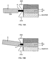
- Fig. 16A is an explanatory diagram of a manner in which coating removal is performed.
- a pair of blades 21A, 23A makes incisions in a coating 5 at a coating removal start position.
- a gripping section (not illustrated - described later) that grips an optical fiber 3 on the left side of Fig. 16A is moved such that the blades 21A, 23A pull off the coating 5, and the coating 5 is removed from the optical fiber 3. Since it is necessary to catch the coating 5 with the blades 21A, 23A during removal of the coating 5, a gap between the pair of blades 21A, 23A is set narrower than the thickness of the coating 5 (the diameter of the optical fiber 3), and slightly wider than the diameter of a bare optical fiber 4.
- the bare optical fiber 4 moves up and down when pulling the coating 5 off, and the blades 21A, 23A may make contact with the bare optical fiber 4.
- the hardness of the blades 21A, 23A is accordingly set lower than the hardness of the bare optical fiber 4 so as to suppress damage to the bare optical fiber 4. As a result, the blade tips gradually wear with repeated removal of the coating 5.
- the coating 5 is removed using the worn blades 21A, 23A, an issue of not being able to completely remove the coating 5, and part of the coating 5 remaining on the bare optical fiber 4, arises.
- the coating 5 remaining on the surface of the bare optical fiber 4 might combust in a weld connection process, reducing the long-term reliability of the optical fiber 3.
- the coating 5 is removed in a state in which one of the blades (the lower side blade 21A in Fig. 16B ) has become worn, a timing at which the worn blade 21A splits the coating 5 is delayed, and slippage occurs between the worn blade 21A and the coating 5.
- unbalanced force acts on the bare optical fiber 4, bending of the bare optical fiber 4 or excessive pressing of the bare optical fiber 4 against. the upper blade 23A might occur, reducing the long-term reliability of the optical fiber 3.
- An objective of some embodiments of the present invention is to prompt blade replacement when a blade has become worn.
- Some embodiments of the present invention are a coating removing device including: a heating section that includes a heater to heat a coating of an optical fiber, and a blade to make an incision in the coating of the optical fiber; a gripping section that grips the optical fiber and is capable of moving with respect to the heating section; and a counter that counts the number of times of coating removal (a "coating removal event number") by detecting separation between the heating section and the gripping section.
- a heating section that includes a heater to heat a coating of an optical fiber, and a blade to make an incision in the coating of the optical fiber
- a gripping section that grips the optical fiber and is capable of moving with respect to the heating section
- a counter that counts the number of times of coating removal (a "coating removal event number") by detecting separation between the heating section and the gripping section.
- Some embodiments of the present invention enable blade replacement to be prompted when a blade has become worn.
- a coating removing device including: a heating section that includes a heater to heat a coating of an optical fiber, and a blade to make an incision in the coating of the optical fiber; a gripping section that grips the optical fiber and is capable of moving with respect to the heating section; and a counter that counts the number of times of coating removal (a "coating removal event number") by detecting separation between the heating section and the gripping section.
- a coating removing device is able to count the coating removal event number and is able to prompt blade replacement when a blade has become worn.
- the counter counts the coating removal event number when a closed state of a lid of the heating section has been detected and separation between the heating section and the gripping section has been detected. This enables the count precision of the coating removal event number to be raised due to not counting the coating removal event number when the lid is in an open state, even when separation between the heating section and the gripping section is detected.
- the counter permits the next counting of the coating removal event number when an open state of the lid of the heating section has been detected. This thereby enables the count precision of the coating removal event number to be raised.
- the counter counts the coating removal event number when heating by the heater of the heating section has been detected and separation between the heating section and the gripping section has been detected. This thereby enables the count precision of the coating removal event number to be raised due to the coating removal event number not being counted when the heating section is not being heated, even when separation between the heating section and the gripping section is detected.
- the gripping section includes a holder housing part that houses a holder retaining the optical fiber; and the counter counts the coating removal event number when the holder has been detected as being housed in the holder housing part and separation between the heating section and the gripping section has been detected. This thereby enables the count precision of the coating removal event number to be raised due to the coating removal event number not being counted when the holder is not housed in the holder housing part, even when separation between the heating section and the gripping section is detected.
- the proximity-retention section uses magnetic force to maintain the heating section and the gripping section in the state in which they have been brought into proximity to each other; and the magnetic force of the proximity-retention section is used to detect separation between the heating section and the gripping section. This thereby enables a reduction in the number of components.
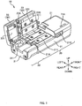
- Fig. 1 is an overall perspective view of a coating removing device 10 of the present embodiment.
- Fig. 2A to Fig. 2C are explanatory diagrams illustrating how coating removal is performed.
- the coating removing device 10 is a device that removes a coating from an optical fiber.
- the target of coating removal in this case is an optical fiber ribbon 1 including a plurality of optical fibers 3; however, application may be made to a single-core optical fiber.
- the coating removing device 10 of the present embodiment is a device that heats and softens a coating material 5 (referred to below simply as the coating) that covers an outer periphery of a bare optical fiber 4 (see Fig. 16A ), reduces adhesive force between the bare optical fiber 4 and the coating, and removes the coating.
- the coating removing device 10 of the present embodiment is also referred to as a hot jacket stripper.
- a movement direction of a body section and a gripping section 30 is taken as a front-to-rear direction, with the side of the body section at the "front” and the side of the gripping section 30 at the "rear”.
- the front-to-rear direction is also sometimes referred to as the "separation direction", the "approach direction”, or the “slide direction”.
- a direction perpendicular to a bottom face of a holder housing part 311 of the gripping section 30 is taken as an "up-and-down direction".
- the side where a holder 7 is housed is “up”, and the opposite side thereto (the side of a gripping-side body 31) is “down”.
- a direction perpendicular to the front-to-rear direction and to the up-and-down direction is taken as a "left-to-right direction”.
- the right side is “right”
- the left side is “left” (in this case the hinge sides of lids (a heating-side lid 23 and a gripping-side lid 33) are on the “left”, and the opening and closing sides thereof are on the "right”).
- the coating removing device 10 includes a heating section 20 and the gripping section 30.
- the heating section 20 is a member that heats the coating of the optical fiber.
- the heating section 20 includes a pair of blades 21A, 23A to remove the coating.
- the heating section 20 includes a heating-side body 21 and a heating-side lid 23. The blades are provided on the heating-side body 21 and the heating-side lid 23, respectively.
- the heating-side body 21 is a member configuring a body of the heating section 20.
- the heating-side body 21 includes the blade 21A and a heater 211.
- the blade 21A is a member that makes an incision in the coating, and catches the coating so as to remove the coating.
- the heater 211 is a heat source to heat the coating of the optical fiber.
- the heater 211 also functions of as a placement section on which to place an end portion of the optical fiber.
- the heater 211 is formed with a groove shape along the front-to-rear direction so as to enable placement thereon of the end portion of the optical fiber in a state in which the end portion of the optical fiber is guided in the front-to-rear direction.
- the heating-side body 21 is provided with a power switch 21B, and an LED lamp 71A (an output section 71) and the like.
- the heating-side lid 23 is a lid member capable of opening and closing with respect to the heating-side body 21.
- the heating-side lid 23 includes the blade 23a and a retention part 231.
- the retention part 231 sandwiches the end portion of the optical fiber between itself and the heater 211 of the heating-side body 21, and is a location to retain the end portion of the optical fiber.
- a heat source to heat the coating of the optical fiber may also be provided to the heating-side lid 23.
- the gripping section 30 is a member that grips the optical fiber.
- the gripping section 30 grips the optical fiber by gripping the holder 7 retaining the optical fiber.
- configuration may be made such that the gripping section 30 grips the optical fiber indirectly through a member other than the holder 7, or grips the optical fiber directly.
- the gripping section 30 is configured so as to be capable of moving in the front-to-rear direction with respect to the heating section 20 (see Fig. 2C ).
- the gripping section 30 includes the gripping-side body 31 and the gripping-side lid 33.
- the gripping-side body 31 is a member configuring a body of the gripping section 30.
- the gripping-side body 31 includes the holder housing part 311.
- the holder housing part 311 is a location to house the holder 7 retaining the optical fiber.
- the gripping-side lid 33 is a lid member capable of opening and closing with respect to the gripping-side body 31.
- the gripping-side lid 33 includes a holder retention part 331.
- the holder retention part 331 sandwiches the holder 7 retaining the optical fiber between itself and the gripping-side body 31, and is a location to grip the holder 7.
- the gripping-side lid 33 is closed, the holder 7 is pressed against the holder housing part 311, such that the holder 7 is gripped between the gripping-side body 31 and the gripping-side lid 33.
- the heating section 20 and the gripping section 30 are connected together by a shaft 41 (see Fig. 2C ).
- the shaft 41 is a member that connects the heating section 20 and the gripping section 30 together, and also guides relative movement between the heating section 20 and the gripping section 30.
- one end of the shaft 41 is fixed to the gripping section 30.
- the shaft 41 may be fixed on the heating section 20 side.
- an operator In order to remove the coating of the optical fiber, an operator first switches on the power switch 21B of the coating removing device 10. The operator then opens the heating-side lid 23 and the gripping-side lid 33, as illustrated in Fig. 2A , houses the holder 7 retaining the optical fiber 3 (the optical fiber ribbon 1 in this case) in the holder housing part 311 of the gripping section 30, and places the end portion of the optical fiber 3 on the heater 211 of the heating-side body 21. The optical fiber 3 is thereby set in the coating removing device 10.
- the operator closes the heating-side lid 23 and the gripping-side lid 33. Incisions are made in the coating of the optical fiber 3 by the pair of blades 21A, 23A when the heating-side lid 23 is closed. Moreover, when the heating-side lid 23 is closed, the end portion of the optical fiber 3 is sandwiched between the heater 211 of the heating-side body 21 and the retention part 231 of the heating-side lid 23, and the coating on the end portion of the optical fiber 3 is heated by the heater 211. Note that, as described later, heating by the heater 211 starts when a lid detector 51 has detected that the heating-side lid 23 is in a closed state. When the coating on the end portion of the optical fiber 3 is heated, the coating softens, reducing the adhesive force between the bare optical fiber 4 and the coating to achieve a state in which the coating is easy to remove.
- the operator moves the gripping section 30 rearward with respect to the heating section 20 in a state in which the heating-side lid 23 and the gripping-side lid 33 are closed.
- the heating section 20 and the gripping section 30 are thereby separated from each other.
- the coating on the end portion of the optical fiber is thus pulled off by the pair of blades 21A, 23A (see Fig. 16A ), and the coating of the optical fiber is removed.
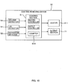
- Fig. 3 is a block diagram illustrating a configuration of the coating removing device 10.
- the coating removing device 10 includes a control section 61, various detectors (such as the lid detector 51), and the output section 71 (such as the LED lamp 71A).
- the control section 61 has a function of overseeing control of the coating removing device 10.
- the control section 61 is, for example, configured from an arithmetic processing unit and a storage device, and various processing is implemented by the arithmetic processing unit executing a program stored in the storage device. Detection results from the various detectors are input to the control section 61.
- the control section 61 controls the heater 211 and the output section 71 based on the detection results of the various detectors.
- the lid detector 51 is a member that detects opening and closing of the heating-side lid 23.
- the lid detector 51 includes a projecting tab 23B (see Fig. 1 ) provided on the heating-side lid 23.
- the lid detector 51 detects that the heating-side lid 23 has been closed (is in a closed state) by a detection part, such as a switch or sensor (not illustrated in Fig. 1 : see Fig. 4A to Fig. 4C ), of the heating-side body 21 detecting the projecting tab 23B when the heating-side lid 23 has been closed.
- Fig. 4A to Fig. 4C are explanatory diagrams of examples of configurations of the lid detector 51 (51A to 51C).
- the lid detector 51A illustrated in Fig. 4A detects the closed state (and the open state) of the heating-side lid 23 by the projecting tab 23B of the heating-side lid 23 (see Fig. 1 ) switching a switch (detection part) of the heating-side body 21 ON or OFF according to opening or closing of the heating-side lid 23.
- a magnetic sensor (detection part) is provided on the heating-side body 21, and a magnet is provided on the projecting tab 23B of the heating-side lid 23.
- the closed state (and the open state) of the heating-side lid 23 is detected from magnetic changes detected by the magnetic sensor (detection part) according to opening and closing of the heating-side lid 23.
- the lid detector 51C illustrated in Fig. 4C detects the closed state (and the open state) of the heating-side lid 23 by the projecting tab 23B of the heating-side lid 23 (see Fig. 1 ) blocking detection light to a photosensor (detection part) of the heating-side body 21 according to opening and closing of the heating-side lid 23.
- the lid detector 51 is not limited to the above configurations as long as the closed state (or the open state) of the heating-side lid 23 can be detected.
- the detection result of the lid detector 51 is output to the control section 61.
- the control section 61 starts heating by the heater 211 when the heating-side lid 23 has been detected to be in the closed state based on the detection result of the lid detector 51. Accordingly, heating of the heater 211 is started automatically when the operator has closed the heating-side lid 23 as illustrated in Fig. 2B .
- the control section 61 stops heating by the heater 211 when the heating-side lid 23 has been detected to be in the open state based on the detection result of the lid detector 51. Accordingly, the heating by the heater 211 is stopped automatically when the operator has opened the heating-side lid 23 and the gripping-side lid 33 to take out the optical fiber after removing the coating.
- the control section 61 thus serves as a heating controller that controls the heater 211.
- control section 61 illuminates the LED lamp 71A (the output section 71) after a predetermined time has elapsed from when the heating-side lid 23 was detected to be in the closed state based on the detection result of the lid detector 51. This enables the operator to be informed that the coating on the end portion of the optical fiber has been heated, and enables the operator to be prompted to perform the moving operation of the gripping section 30 illustrated in Fig. 2C .
- the control section 61 thus serves as an output controller that controls the output section 71.
- the coating removing device 10 includes, as the output section 71, a display section such as the LED lamp 71A, a speaker (not illustrated) that outputs sound, or the like.
- the LED lamp 71A or the speaker (not illustrated) serve as a notification section to notify that the number of times of coating removal ("coating removal event number") has reached a predetermined value, as described later.
- the coating removing device 10 may include, as the output section 71, a display section capable of displaying numerical values (for example a count value, described later).
- a display section (the output section 71) capable of displaying a count value may be a small liquid crystal monitor also capable of displaying information other than numerical values, a segment display device with a primary purpose of displaying numerical values, or the like.
- the coating removing device 10 may also include, as the output section 71, a communication section that exchanges data (data including a count value, described later) with an external device.
- coating removal event number the number of times of coating removal
- the coating removal event number is counted by detecting separation of the heating section 20 and the gripping section 30.
- the coating removing device 10 includes a separation detector 52 to detect separation of the heating section 20 and the gripping section 30 (see Fig. 3 ).
- Fig. 5A to Fig. 5C are explanatory diagrams illustrating example configurations of the separation detector 52 (52A to 52C).
- the separation detector 52A illustrated in Fig. 5A is configured by a mechanical switch.
- the diagram at the top of Fig. 5A is an explanatory diagram illustrating a state (proximity state) prior to the separation detector 52A detecting separation of the heating section 20 and the gripping section 30.
- the diagram at the bottom of Fig. 5A is an explanatory diagram illustrating a state (separated state) in which separation of the heating section 20 and the gripping section 30 has detected by the separation detector 52A.
- the 5A detects the separated state (or the proximity state) of the heating section 20 and the gripping section 30 by the switch (detection part) of the heating-side body 21 being switched ON or OFF according to proximity/separation of the heating section 20 and the gripping section 30.
- the separation detector 52A is disposed on a face where the heating section 20 and the gripping section 30 oppose each other.
- the switch configuring the separation detector 52A is disposed on the heating section 20, and the switch is switched ON or OFF by the proximity/separation of the opposing face (detected part) of the gripping section 30 to the switch.
- the switch configuring the separation detector 52A may also be disposed on the gripping section 30 side.
- the separation detector 52B illustrated in Fig. 5B is configured by a magnetic sensor.
- the magnetic sensor (detection part) is provided on the heating-side body 21, and a magnet (detected part) is provided on the gripping section 30.
- the separation detector 52A illustrated in Fig. 5B detects the separated state (or the proximity state) of the heating section 20 and the gripping section 30 using magnetic changes detected by the magnetic sensor (detection part) according to the proximity/separation of the heating section 20 and the gripping section 30.
- the separation detector 52C illustrated in Fig. 5C is configured by a photosensor.
- the photosensor (detection part) is provided on the heating-side body 21, and a light-blocking tab (detected part) is provided on the gripping section 30.
- the separation detector 52C detects the separated state (or the proximity state) of the heating section 20 and the gripping section 30 by the light-blocking tab blocking/projecting detection light of the photosensor (detection part) according to the proximity/separation of the heating section 20 and the gripping section 30.
- the separation detector 52 is not limited to the configurations illustrated in Fig. 5A to Fig. 5C .
- the coating removing device 10 includes a counter 61A to count the coating removal event number (see Fig. 3 ).
- the counter 61A is configured by the control section 61; however, the counter 61A may be configured by a mechanical counter.
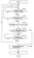
- Fig. 6 is an explanatory diagram illustrating processing to count the coating removal event number in the first embodiment.
- the counter 61A determines whether or not a closed state of the heating-side lid 23 is being detected based on the detection result of the lid detector 51 (S101). As long as the closed state of the heating-side lid 23 is not being detected (S101: NO), the counter 61A repeats the determination processing of the S101 until the closed state of the heating-side lid 23 has been detected. When the closed state of the heating-side lid 23 has been detected (S101: YES), the counter 61A then determines whether or not the separated state of the heating section 20 and the gripping section 30 is being detected based on the detection result of the separation detector 52 (S102).
- the counter 61A increments the count value of the coating removal event number by one (S103) when the closed state of the heating-side lid 23 has been detected based on the detection result of the lid detector 51 (S101: YES), and the separated state of the heating section 20 and the gripping section 30 has been detected based on the detection result of the separation detector 52 (S102: YES). Accordingly, the count value indicating the coating removal event number can be increased by one when, as illustrated in Fig.
- the counter 61A stores the count value in the storage device.
- an increase in the count value can be suppressed from occurring when the coating is not being removed, thereby enabling the count precision of the coating removal event number (the precision of matching between the coating removal event number and the count value) to be raised.
- the counter 61A permits the next counting of the coating removal event number (S101 to S103) when the open state of the heating-side lid 23 has been detected (S105: YES) subsequent to incrementing the count value by one (S103).
- the coating removal event number is not next counted until after the open state of the heating-side lid 23 is detected (S105: YES). This is because after the coating on the end portion of the optical fiber has been removed, as illustrated in Fig.
- the count precision of the coating removal event number (the precision of matching between the coating removal event number and the count value) can be raised.
- configuration may be made such that the next counting of the coating removal event number is permitted regardless of whether or not the open state of the heating-side lid 23 has been detected.
- the control section 61 when the count value has reached a predetermined value (S104: YES), the control section 61 notifies the output section 71 that the coating removal event number has reached the predetermined value. Specifically, when the count value has reached the predetermined value (S104: YES), the control section 61 illuminates the LED lamp 71A configuring the output section 71, and thereby notifies the operator that the coating removal event number has reached the predetermined value (S106) . The operator can thus be prompted to replace the blades 21A, 23A when the blades 21A, 23A have become worn.
- the notification method of the output section 71 is not limited to illumination of the LED lamp 71A. For example, when the count value has reached the predetermined value (S104: YES), the control section 61 may sound a buzzer using a speaker configuring the output section 71, thereby notifying the operator that the coating removal event number has reached the predetermined value.
- the control section 61 may display the count value of the coating removal event number on the display section (output section 71).
- the count value display is not limited to an electronic display, and may be a mechanical (such as a dial) display. To display the count value, the control section 61 may determine whether or not the count value has reached the predetermined value (S104) without using the output section 71 for notification (S106).
- the counter 61A increments the count value of the coating removal event number by one (S103) when the closed state of the heating-side lid 23 has been detected based on the detection result of the lid detector 51 (S101: YES), and the separated state of the heating section 20 and the gripping section 30 has been detected based on the detection result of the separation detector 52 (S102: YES).
- detection of heating by the heater 211 may be employed instead of detection of the closed state of the heating-side lid 23 (S101).
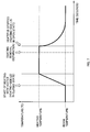
- Fig. 7 is an explanatory diagram of a heating profile of the heater 211.
- the horizontal axis of the graph in Fig. 7 indicates time, and the vertical axis indicates the temperature of the heater 211.
- the control section 61 (heating controller) starts heating by the heater 211 when the closed state of the heating-side lid 23 has been detected based on the detection result of the lid detector 51.
- the temperature of the heater 211 rises when heating by the heater 211 is started, and reaches a predetermined heating temperature.
- the control section 61 performs constant temperature control on the heater 211 so as to sustain the predetermined heating temperature, and stops heating by the heater 211 when the open state of the heating-side lid 23 has been detected.
- Fig. 8 is a block diagram illustrating a configuration of the coating removing device 10 of the second embodiment.
- the coating removing device 10 of the second embodiment includes a heating detector 53.
- the heating detector 53 is a member that detects heating by the heater 211.
- the heating detector 53 may be a temperature sensor that detects heating by the heater 211 based on a detected temperature. In such cases, a detection result of the temperature sensor of the heating detector 53 may be employed in the constant temperature control (see Fig. 7 ) of the heater 211.
- the heating detector 53 may also detect heating by the heater 211 by detecting electrical conduction to the heater 211.
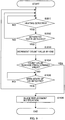
- Fig. 9 is an explanatory diagram of processing to count the coating removal event number in the second embodiment.
- the counter 61A determines whether or not heating by the heater 211 has been detected based on the detection result of the heating detector 53 (S201) . As long as heating by the heater 211 is not being detected (S201: NO), the counter 61A repeats the determination processing of S201 until heating by the heater 211 is detected. When heating by the heater 211 has been detected (S201: YES), the counter 61A then determines whether or not the separated state of the heating section 20 and the gripping section 30 has been detected based on the detection result of the separation detector 52 (S202) .
- the counter 61A returns to the determination processing of S201.
- the counter 61A increments the count value of the coating removal event number by one (S203).
- the counter 61A increments the count value of the coating removal event number by one (S203) when heating by the heater 211 has been detected based on the detection result of the heating detector 53 (S201: YES), and the separated state of the heating section 20 and the gripping section 30 has been detection based on the detection result of the separation detector 52 (S202: YES).
- the counter 61A may determine whether or not heating has been started, or may determine whether or not the heater 211 has reached a predetermined temperature based on the detection result of the temperature sensor.
- the count value is not incremented when heating is not being performed in the heater 211, even if the separated state of the heating section 20 and the gripping section 30 is detected. This is because the heater 211 is in a heated state when the heating section 20 and the gripping section 30 are separated to remove the coating.
- the count value can be suppressed from increasing when the coating is not being removed, thereby enabling the count precision of the coating removal event number (the precision of matching between the coating removal event number and the count value) to be raised.
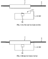
- Fig. 10 is a block diagram illustrating a configuration of a coating removing device 10 of a third embodiment.
- the coating removing device 10 of the third embodiment includes a holder detector 54.
- Fig. 11A and Fig. 11B are explanatory diagrams of the holder detector 54.
- Fig. 11A is an explanatory diagram illustrating a state prior to the holder detector 54 detecting the holder 7 (a pre-detection state).
- Fig. 11B is an explanatory diagram illustrating a state in which the holder detector 54 has detected the holder 7 (detection state).
- the holder detector 54 is a member to detect the holder 7 housed in the holder housing part 311 of the gripping section 30.
- the holder detector 54 is configured by a switch that is switched ON and OFF accordingly to mounting and demounting of the holder 7 to and from the holder housing part 311.
- the holder detector 54 may also be configured by a sensor (magnetic sensor, photosensor, or the like) that detects the holder 7 magnetically or optically.
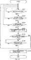
- Fig. 12 is an explanatory diagram of processing to count the coating removal event number in the third embodiment.
- the counter 61A determines whether or not the holder 7 is being detected as housed in the holder housing part 311 based on the detection result of the holder detector 54 (S301). As long as the holder 7 is not being detected as being housed in the holder housing part 311 (S301: NO), the counter 61A repeats the determination processing of S301 until the holder is detected. When the holder 7 has been detected as being housed in the holder housing part 311 (S301: YES), the counter 61A then determines whether or not the closed state of the heating-side lid 23 has been detected based on the detection result of the lid detector 51 (S302).
- the counter 61A determines whether or not the separated state of the heating section 20 and the gripping section 30 is being detected based on the detection result of the separation detector 52 (S303) .
- the counter 61A returns to the determination processing of S301.
- the counter 61A increments the count value of the coating removal event number by one (S304).
- the counter 61A increments the count value of the coating removal event number by one (S304) when the holder 7 has been detected as being housed in the holder housing part 311 based on the detection result of the holder detector 54 (S301: YES), and the closed state of the heating-side lid 23 has been detected based on the detection result of the lid detector 51 (S302: YES), and the separated state of the heating section 20 and the gripping section 30 has been detected based on the detection result of the separation detector 52 (S303: YES).
- the count value is not incremented when the holder 7 is not housed in the holder housing part 311, even when the separated state of the heating section 20 and the gripping section 30 is detected with the heating-side lid 23 in the closed state. This thereby enables the count precision of the coating removal event number (the precision of matching between the coating removal event number and the count value) to be raised.
- the counter 61A increments the count value of the coating removal event number by one (S304) when the holder 7 has been detected as being housed in the holder housing part 311 based on the detection result of the holder detector 54 (S301: YES), and the separated state of the heating section 20 and the gripping section 30 has been detected based on the detection result of the separation detector 52 (S303: YES).
- Adopting such a configuration still enables the count precision of the coating removal event number (the precision of matching between the coating removal event number and the count value) to be raised since it is possible to prevent the count value of the coating removal event number from being incremented when the holder 7 is not being housed in the holder housing part 311.
- the separation detectors 52 illustrated in Fig. 5A to Fig. 5C are each disposed on an opposing face of the heating section 20 or the gripping section 30. However, the placement and configuration of the separation detector 52 are not limited thereto.
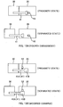
- Fig. 13A is an explanatory diagram of a separation detector 52 of a fourth embodiment.
- the diagram at the top of Fig. 13A is an explanatory diagram illustrating a state (proximity state) prior to the separation detector 52 detecting separation of the heating section 20 and the gripping section 30.
- the diagram at the bottom of Fig. 13A is an explanatory diagram illustrating a state (separated state) in which the separation detector 52 has detected separation of the heating section 20 and the gripping section 30.
- a shaft 41 in Fig. 13A is a member that connects the heating section 20 and the gripping section 30 together, and that guides relative movement of the heating section 20 and the gripping section 30 (see also Fig. 2C ). Note that one end (a rear end, the end portion on the left side in Fig. 13A ) of the shaft 41 is fixed to the gripping section 30, and the other end of the shaft 41 moves inside the heating section 20 when the gripping section 30 moves with respect to the heating section 20.
- the separation detector 52 of the fourth embodiment detects separation of the heating section 20 and the gripping section 30 by detecting movement of the shaft 41 when the heating section 20 and the gripping section 30 are separated from each other.
- the separation detector 52 is configured here by a mechanical switch, and the switch (detection part) is disposed facing the heating section 20 side end portion (detected part) of the shaft 41.
- the separation detector 52 detects the separated state (or the proximity state) of the heating section 20 and the gripping section 30 due to the shaft 41 separating from the switch when the heating section 20 and the gripping section 30 are separated.
- Fig. 13B is an explanatory diagram of a separation detector 52 of a modified example of the fourth embodiment.
- a gripping section 30 side end portion of the shaft 41 is fixed to the gripping section 30, and a flange portion 41B projecting out further toward the outside than a shaft portion 41A of the shaft 41 is formed to a heating section 20 side end portion of the shaft 41.
- a switch (detection part) configuring the separation detector 52 is disposed at a position facing the shaft portion 41A of the shaft 41 when in the proximity state, and is disposed at a position facing the flange portion 41B (detected part) of the shaft 41 when a movement amount of the shaft 41 has reached a predetermined amount.
- the separation detector 52 is thus capable of detecting separation of the heating section 20 and the gripping section 30 due to the switch contacting the flange portion 41B and being switched ON or OFF when the movement amount of the shaft 41 has reached the predetermined amount.
- the counter 61A is thereby able to detect the separated state of the heating section 20 and the gripping section 30 based on the detection result of the separation detector 52 (see S102, S202, S303) when the heating section 20 and the gripping section 30 have separated from each other by a predetermined amount or greater.
- the count value of the coating removal event number is not incremented as long as the heating section 20 and the gripping section 30 are not separated by the predetermined amount or greater. This thereby enables the count precision of the coating removal event number (the precision of matching between the coating removal event number and the count value) to be raised.
- the one end of the shaft 41 is fixed to the gripping section 30, and the switch (detection part) of the separation detector 52 is disposed in the heating section 20.
- the one end of the shaft 41 may be fixed to the gripping section 30 and a switch configuring the separation detector 52 disposed in the gripping section 30.
- the separation detector 52 is configured using a switch; however, the separation detector 52 may be configured using a sensor (magnetic sensor, photosensor, or the like) that detects the holder 7 magnetically or optically.
- the count value of the coating removal event number may be incremented by one when the separated state of the heating section 20 and the gripping section 30 has been detected, without the addition of any other condition.
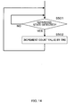
- Fig. 14 is an explanatory diagram illustrating processing to count the coating removal event number in a fifth embodiment.
- the counter 61A increments the count value of the coating removal event number by one (S502) when the separated state of the heating section 20 and the gripping section 30 has been detected based on the detection result of the separation detector 52 (S501: YES). Merely performing this processing still enables the count value representing the coating removal event number to be increased by one when an operator has separated the heating section 20 and the gripping section 30 and removed the coating on the end portion of the optical fiber (see Fig. 2C ).
- the coating removing device 10 preferably includes a proximity-retention section 45 to maintain the heating section 20 and the gripping section 30 in a state in which they have been brought into proximity to each other.
- Fig. 15A and Fig. 15B are explanatory diagrams illustrating example configurations of the proximity-retention section 45.
- the proximity-retention section 45 illustrated in Fig. 15A includes a magnet and a magnetic body.
- the magnet is disposed in the gripping section 30, and the magnetic body is disposed in the heating section 20, and magnetic force is used to maintain the heating section 20 and the gripping section 30 in the proximity state.
- the magnet may be disposed in the heating section 20, and the magnetic body may be disposed in the gripping section 30.
- a magnet disposed in an attracting orientation may be disposed instead of the magnetic body.
- the magnetic force of the magnet of the proximity-retention section 45 may be used to detect separation of the heating section 20 and the gripping section.
- the magnetic sensor (separation detector 52) illustrated in Fig. 5B may be disposed so as to face the magnet (the magnet configuring the proximity-retention section 45) of the gripping section 30 in Fig. 15A . This thereby enables the magnet to be employed in both the separation detector 52 and the proximity-retention section 45, enabling a reduction in the number of components.
- the proximity-retention section 45 illustrated in Fig. 15B is configured by a coil spring.
- the coil spring is disposed in a compressed state between an inner wall face of the heating section 20 and the flange portion 41B of the shaft 41. Due to the coil spring being disposed in a pre-compressed state, the rebound force of the coil spring maintains the heating section 20 and the gripping section 30 in the state in which they have been brought into proximity to each other.
- the coating removing device 10 is provided with the proximity-retention section 45 that maintains the heating section 20 and the gripping section 30 in the state in which they have been brought into proximity to each other, separation of the heating section 20 and the gripping section 30 can be suppressed when the coating is not being removed. This thereby enables the count precision of the coating removal event number (the precision of matching between the coating removal event number and the count value) to be raised.
Landscapes
- Physics & Mathematics (AREA)
- General Physics & Mathematics (AREA)
- Optics & Photonics (AREA)
- Light Guides In General And Applications Therefor (AREA)
Abstract
Description
- The present invention relates to a coating removing device for an optical fiber.
- Known examples of coating removing devices to remove a coating of an optical fiber include devices such as those described in
Patent Literature 1 and 2. The coating removing devices described inPatent Literature 1 and 2 heat and soften a coating to be removed from an optical fiber, reduce adhesive force between the bare optical fiber and the coating, and remove the coating. -
- Patent Literature 1: Japanese Unexamined Utility Model Application Publication No.
H01-90003 - Patent Literature 2: Japanese Unexamined Patent Application Publication No.
2002-328241 -
Fig. 16A is an explanatory diagram of a manner in which coating removal is performed. A pair ofblades optical fiber 3 on the left side ofFig. 16A is moved such that theblades optical fiber 3. Since it is necessary to catch the coating 5 with theblades blades optical fiber 4. - Due to the gap between the pair of
blades optical fiber 4, the bareoptical fiber 4 moves up and down when pulling the coating 5 off, and theblades optical fiber 4. The hardness of theblades optical fiber 4 so as to suppress damage to the bareoptical fiber 4. As a result, the blade tips gradually wear with repeated removal of the coating 5. - If the coating 5 is removed using the
worn blades optical fiber 4, arises. In cases in which part of the coating 5 remains on the bareoptical fiber 4 and a subsequent cleaning process is not able to completely remove the coating 5, the coating 5 remaining on the surface of the bareoptical fiber 4 might combust in a weld connection process, reducing the long-term reliability of theoptical fiber 3. - Moreover if, as illustrated in
Fig. 16B , the coating 5 is removed in a state in which one of the blades (thelower side blade 21A inFig. 16B ) has become worn, a timing at which theworn blade 21A splits the coating 5 is delayed, and slippage occurs between theworn blade 21A and the coating 5. This results in an issue of force acting on the bareoptical fiber 4 becoming unbalanced. When unbalanced force acts on the bareoptical fiber 4, bending of the bareoptical fiber 4 or excessive pressing of the bareoptical fiber 4 against. theupper blade 23A might occur, reducing the long-term reliability of theoptical fiber 3. - In order to prevent issues such as those described above, it is desirable to replace the blades when the blades become worn. However, due to the difficulty in assessing the amount of wear of the blades by sight, it is easy to perform coating removal without noticing that the blades are due for replacement.
- An objective of some embodiments of the present invention is to prompt blade replacement when a blade has become worn.
- Some embodiments of the present invention are a coating removing device including: a heating section that includes a heater to heat a coating of an optical fiber, and a blade to make an incision in the coating of the optical fiber; a gripping section that grips the optical fiber and is capable of moving with respect to the heating section; and a counter that counts the number of times of coating removal (a "coating removal event number") by detecting separation between the heating section and the gripping section.
- Other features of the present invention are made clear by the Description and Drawings below.
- Some embodiments of the present invention enable blade replacement to be prompted when a blade has become worn.
-
-
Fig. 1 is an overall perspective view of acoating removing device 10 of an embodiment. -
Fig. 2A to Fig. 2C are explanatory diagrams illustrating how coating removal is performed. -
Fig. 3 is a block diagram illustrating a configuration of thecoating removing device 10. -
Fig. 4A to Fig. 4C are explanatory diagrams of examples of configurations of alid detector 51. -
Fig. 5A to Fig. 5C are explanatory diagrams of examples of configurations of aseparation detector 52. -
Fig. 6 is an explanatory diagram of processing to count a coating removal event number in a first embodiment. -
Fig. 7 is an explanatory diagram illustrating a heating profile of aheater 211. -
Fig. 8 is a block diagram illustrating a configuration of acoating removing device 10 of a second embodiment. -
Fig. 9 is an explanatory diagram illustrating processing to count the coating removal event number in the second embodiment. -
Fig. 10 is a block diagram illustrating a configuration of acoating removing device 10 of a third embodiment. -
Fig. 11A and Fig. 11B are explanatory diagrams of aholder detector 54. -
Fig. 12 is an explanatory diagram of processing to count the coating removal event number in the third embodiment. -
Fig. 13A is an explanatory diagram of aseparation detector 52 of a fourth embodiment.Fig. 13B is an explanatory diagram of aseparation detector 52 of a modified example of the fourth embodiment. -
Fig. 14 is an explanatory diagram of processing to count the coating removal event number in a fifth embodiment. -
Fig. 15A and Fig. 15B are explanatory diagrams of examples of configurations of a proximity-retention section. -
Fig. 16A is an explanatory diagram illustrating how coating removal is performed.Fig. 16B is an explanatory diagram illustrating how coating removal is performed when a blade has become worn. - At least the following matters are made clear from the Description and Drawings described below.
- Disclosed is a coating removing device including: a heating section that includes a heater to heat a coating of an optical fiber, and a blade to make an incision in the coating of the optical fiber; a gripping section that grips the optical fiber and is capable of moving with respect to the heating section; and a counter that counts the number of times of coating removal (a "coating removal event number") by detecting separation between the heating section and the gripping section. Such a coating removing device is able to count the coating removal event number and is able to prompt blade replacement when a blade has become worn.
- It is preferable that the counter counts the coating removal event number when a closed state of a lid of the heating section has been detected and separation between the heating section and the gripping section has been detected. This enables the count precision of the coating removal event number to be raised due to not counting the coating removal event number when the lid is in an open state, even when separation between the heating section and the gripping section is detected.
- It is preferable that, after the counter has counted the coating removal event number, the counter permits the next counting of the coating removal event number when an open state of the lid of the heating section has been detected. This thereby enables the count precision of the coating removal event number to be raised.
- It is preferable that the counter counts the coating removal event number when heating by the heater of the heating section has been detected and separation between the heating section and the gripping section has been detected. This thereby enables the count precision of the coating removal event number to be raised due to the coating removal event number not being counted when the heating section is not being heated, even when separation between the heating section and the gripping section is detected.
- It is preferable that: the gripping section includes a holder housing part that houses a holder retaining the optical fiber; and the counter counts the coating removal event number when the holder has been detected as being housed in the holder housing part and separation between the heating section and the gripping section has been detected. This thereby enables the count precision of the coating removal event number to be raised due to the coating removal event number not being counted when the holder is not housed in the holder housing part, even when separation between the heating section and the gripping section is detected.
- It is preferable to further include a shaft that connects the heating section and the gripping section together and guides separation between the heating section and the gripping section, and preferable that separation between the heating section and the gripping section is detected by detecting that a movement amount of the shaft has reached a predetermined amount when the heating section and the gripping section have been separated. This thereby enables the count precision of the coating removal event number to be raised due to the coating removal event number not being counted as long as the heating section and the gripping section have not been separated by a predetermined amount or greater.
- It is preferable to further include a proximity-retention section that maintains the heating section and the gripping section in a state in which they have been brought into proximity to each other. This thereby enables the count precision of the coating removal event number to be raised due to being able to suppress separation of the heating section and the gripping section when the coating is not being removed.
- It is preferable that: the proximity-retention section uses magnetic force to maintain the heating section and the gripping section in the state in which they have been brought into proximity to each other; and the magnetic force of the proximity-retention section is used to detect separation between the heating section and the gripping section. This thereby enables a reduction in the number of components.
- It is preferable to further include a notification section to notify that the coating removal event number has reached a predetermined value. This thereby enables an operator to be prompted to replace the blade.
- It is preferable to further include a display section to display the coating removal event number. This thereby enables an operator to be prompted to replace the blade.
-
Fig. 1 is an overall perspective view of acoating removing device 10 of the present embodiment.Fig. 2A to Fig. 2C are explanatory diagrams illustrating how coating removal is performed. - The
coating removing device 10 is a device that removes a coating from an optical fiber. The target of coating removal in this case is anoptical fiber ribbon 1 including a plurality ofoptical fibers 3; however, application may be made to a single-core optical fiber. Thecoating removing device 10 of the present embodiment is a device that heats and softens a coating material 5 (referred to below simply as the coating) that covers an outer periphery of a bare optical fiber 4 (seeFig. 16A ), reduces adhesive force between the bareoptical fiber 4 and the coating, and removes the coating. Thecoating removing device 10 of the present embodiment is also referred to as a hot jacket stripper. - In the following explanation sometimes reference is made to the directions illustrated in
Fig. 1 . Namely, a movement direction of a body section and agripping section 30 is taken as a front-to-rear direction, with the side of the body section at the "front" and the side of the grippingsection 30 at the "rear". Note that the front-to-rear direction is also sometimes referred to as the "separation direction", the "approach direction", or the "slide direction". A direction perpendicular to a bottom face of aholder housing part 311 of the grippingsection 30 is taken as an "up-and-down direction". As viewed from the bottom face of theholder housing part 311, the side where aholder 7 is housed is "up", and the opposite side thereto (the side of a gripping-side body 31) is "down". Moreover, a direction perpendicular to the front-to-rear direction and to the up-and-down direction is taken as a "left-to-right direction". As viewed from the rear side, the right side is "right", and the left side is "left" (in this case the hinge sides of lids (a heating-side lid 23 and a gripping-side lid 33) are on the "left", and the opening and closing sides thereof are on the "right"). - The
coating removing device 10 includes aheating section 20 and the grippingsection 30. - The
heating section 20 is a member that heats the coating of the optical fiber. Theheating section 20 includes a pair ofblades heating section 20 includes a heating-side body 21 and a heating-side lid 23. The blades are provided on the heating-side body 21 and the heating-side lid 23, respectively. - The heating-
side body 21 is a member configuring a body of theheating section 20. The heating-side body 21 includes theblade 21A and aheater 211. Theblade 21A is a member that makes an incision in the coating, and catches the coating so as to remove the coating. Theheater 211 is a heat source to heat the coating of the optical fiber. Theheater 211 also functions of as a placement section on which to place an end portion of the optical fiber. Specifically, theheater 211 is formed with a groove shape along the front-to-rear direction so as to enable placement thereon of the end portion of the optical fiber in a state in which the end portion of the optical fiber is guided in the front-to-rear direction. The heating-side body 21 is provided with apower switch 21B, and anLED lamp 71A (an output section 71) and the like. - The heating-
side lid 23 is a lid member capable of opening and closing with respect to the heating-side body 21. The heating-side lid 23 includes the blade 23a and aretention part 231. Theretention part 231 sandwiches the end portion of the optical fiber between itself and theheater 211 of the heating-side body 21, and is a location to retain the end portion of the optical fiber. When the heating-side lid 23 is closed, the end portion of the optical fiber is pressed against theheater 211 so as to be heated by theheater 211. Note that a heat source (heater 211) to heat the coating of the optical fiber may also be provided to the heating-side lid 23. - The gripping
section 30 is a member that grips the optical fiber. In the present embodiment, the grippingsection 30 grips the optical fiber by gripping theholder 7 retaining the optical fiber. However, configuration may be made such that the grippingsection 30 grips the optical fiber indirectly through a member other than theholder 7, or grips the optical fiber directly. The grippingsection 30 is configured so as to be capable of moving in the front-to-rear direction with respect to the heating section 20 (seeFig. 2C ). The grippingsection 30 includes the gripping-side body 31 and the gripping-side lid 33. - The gripping-
side body 31 is a member configuring a body of the grippingsection 30. The gripping-side body 31 includes theholder housing part 311. Theholder housing part 311 is a location to house theholder 7 retaining the optical fiber. - The gripping-
side lid 33 is a lid member capable of opening and closing with respect to the gripping-side body 31. The gripping-side lid 33 includes aholder retention part 331. Theholder retention part 331 sandwiches theholder 7 retaining the optical fiber between itself and the gripping-side body 31, and is a location to grip theholder 7. When the gripping-side lid 33 is closed, theholder 7 is pressed against theholder housing part 311, such that theholder 7 is gripped between the gripping-side body 31 and the gripping-side lid 33. - The
heating section 20 and the grippingsection 30 are connected together by a shaft 41 (seeFig. 2C ). Theshaft 41 is a member that connects theheating section 20 and the grippingsection 30 together, and also guides relative movement between theheating section 20 and the grippingsection 30. In the present embodiment, one end of theshaft 41 is fixed to the grippingsection 30. When the grippingsection 30 moves with respect to theheating section 20, theshaft 41 also moves with respect to theheating section 20. However, theshaft 41 may be fixed on theheating section 20 side. - In order to remove the coating of the optical fiber, an operator first switches on the
power switch 21B of thecoating removing device 10. The operator then opens the heating-side lid 23 and the gripping-side lid 33, as illustrated inFig. 2A , houses theholder 7 retaining the optical fiber 3 (theoptical fiber ribbon 1 in this case) in theholder housing part 311 of the grippingsection 30, and places the end portion of theoptical fiber 3 on theheater 211 of the heating-side body 21. Theoptical fiber 3 is thereby set in thecoating removing device 10. - Next, as illustrated in
Fig. 2B , the operator closes the heating-side lid 23 and the gripping-side lid 33. Incisions are made in the coating of theoptical fiber 3 by the pair ofblades side lid 23 is closed. Moreover, when the heating-side lid 23 is closed, the end portion of theoptical fiber 3 is sandwiched between theheater 211 of the heating-side body 21 and theretention part 231 of the heating-side lid 23, and the coating on the end portion of theoptical fiber 3 is heated by theheater 211. Note that, as described later, heating by theheater 211 starts when alid detector 51 has detected that the heating-side lid 23 is in a closed state. When the coating on the end portion of theoptical fiber 3 is heated, the coating softens, reducing the adhesive force between the bareoptical fiber 4 and the coating to achieve a state in which the coating is easy to remove. - Next, as illustrated in
Fig. 2C , the operator moves the grippingsection 30 rearward with respect to theheating section 20 in a state in which the heating-side lid 23 and the gripping-side lid 33 are closed. Theheating section 20 and the grippingsection 30 are thereby separated from each other. The coating on the end portion of the optical fiber is thus pulled off by the pair ofblades Fig. 16A ), and the coating of the optical fiber is removed. -
Fig. 3 is a block diagram illustrating a configuration of thecoating removing device 10. Thecoating removing device 10 includes acontrol section 61, various detectors (such as the lid detector 51), and the output section 71 (such as theLED lamp 71A). - The
control section 61 has a function of overseeing control of thecoating removing device 10. Thecontrol section 61 is, for example, configured from an arithmetic processing unit and a storage device, and various processing is implemented by the arithmetic processing unit executing a program stored in the storage device. Detection results from the various detectors are input to thecontrol section 61. Thecontrol section 61 controls theheater 211 and theoutput section 71 based on the detection results of the various detectors. - The
lid detector 51 is a member that detects opening and closing of the heating-side lid 23. Thelid detector 51 includes a projectingtab 23B (seeFig. 1 ) provided on the heating-side lid 23. Thelid detector 51 detects that the heating-side lid 23 has been closed (is in a closed state) by a detection part, such as a switch or sensor (not illustrated inFig. 1 : seeFig. 4A to Fig. 4C ), of the heating-side body 21 detecting the projectingtab 23B when the heating-side lid 23 has been closed. -
Fig. 4A to Fig. 4C are explanatory diagrams of examples of configurations of the lid detector 51 (51A to 51C). Thelid detector 51A illustrated inFig. 4A detects the closed state (and the open state) of the heating-side lid 23 by the projectingtab 23B of the heating-side lid 23 (seeFig. 1 ) switching a switch (detection part) of the heating-side body 21 ON or OFF according to opening or closing of the heating-side lid 23. In thelid detector 51B illustrated inFig. 4B , a magnetic sensor (detection part) is provided on the heating-side body 21, and a magnet is provided on the projectingtab 23B of the heating-side lid 23. The closed state (and the open state) of the heating-side lid 23 is detected from magnetic changes detected by the magnetic sensor (detection part) according to opening and closing of the heating-side lid 23. Thelid detector 51C illustrated inFig. 4C detects the closed state (and the open state) of the heating-side lid 23 by the projectingtab 23B of the heating-side lid 23 (seeFig. 1 ) blocking detection light to a photosensor (detection part) of the heating-side body 21 according to opening and closing of the heating-side lid 23. Note that thelid detector 51 is not limited to the above configurations as long as the closed state (or the open state) of the heating-side lid 23 can be detected. - The detection result of the
lid detector 51 is output to thecontrol section 61. Thecontrol section 61 starts heating by theheater 211 when the heating-side lid 23 has been detected to be in the closed state based on the detection result of thelid detector 51. Accordingly, heating of theheater 211 is started automatically when the operator has closed the heating-side lid 23 as illustrated inFig. 2B . Moreover, thecontrol section 61 stops heating by theheater 211 when the heating-side lid 23 has been detected to be in the open state based on the detection result of thelid detector 51. Accordingly, the heating by theheater 211 is stopped automatically when the operator has opened the heating-side lid 23 and the gripping-side lid 33 to take out the optical fiber after removing the coating. Thecontrol section 61 thus serves as a heating controller that controls theheater 211. - Moreover, the
control section 61 illuminates theLED lamp 71A (the output section 71) after a predetermined time has elapsed from when the heating-side lid 23 was detected to be in the closed state based on the detection result of thelid detector 51. This enables the operator to be informed that the coating on the end portion of the optical fiber has been heated, and enables the operator to be prompted to perform the moving operation of the grippingsection 30 illustrated inFig. 2C . Thecontrol section 61 thus serves as an output controller that controls theoutput section 71. - The
coating removing device 10 includes, as theoutput section 71, a display section such as theLED lamp 71A, a speaker (not illustrated) that outputs sound, or the like. TheLED lamp 71A or the speaker (not illustrated) serve as a notification section to notify that the number of times of coating removal ("coating removal event number") has reached a predetermined value, as described later. - The
coating removing device 10 may include, as theoutput section 71, a display section capable of displaying numerical values (for example a count value, described later). A display section (the output section 71) capable of displaying a count value may be a small liquid crystal monitor also capable of displaying information other than numerical values, a segment display device with a primary purpose of displaying numerical values, or the like. Thecoating removing device 10 may also include, as theoutput section 71, a communication section that exchanges data (data including a count value, described later) with an external device. - In the present embodiment, the number of times of coating removal ("coating removal event number") is counted to prompt replacement of the
blades blades heating section 20 and the grippingsection 30. - The
coating removing device 10 includes aseparation detector 52 to detect separation of theheating section 20 and the gripping section 30 (seeFig. 3 ).Fig. 5A to Fig. 5C are explanatory diagrams illustrating example configurations of the separation detector 52 (52A to 52C). - The
separation detector 52A illustrated inFig. 5A is configured by a mechanical switch. The diagram at the top ofFig. 5A is an explanatory diagram illustrating a state (proximity state) prior to theseparation detector 52A detecting separation of theheating section 20 and the grippingsection 30. The diagram at the bottom ofFig. 5A is an explanatory diagram illustrating a state (separated state) in which separation of theheating section 20 and the grippingsection 30 has detected by theseparation detector 52A. Theseparation detector 52A illustrated inFig. 5A detects the separated state (or the proximity state) of theheating section 20 and the grippingsection 30 by the switch (detection part) of the heating-side body 21 being switched ON or OFF according to proximity/separation of theheating section 20 and the grippingsection 30. Theseparation detector 52A is disposed on a face where theheating section 20 and the grippingsection 30 oppose each other. In this case, the switch configuring theseparation detector 52A is disposed on theheating section 20, and the switch is switched ON or OFF by the proximity/separation of the opposing face (detected part) of the grippingsection 30 to the switch. Note that the switch configuring theseparation detector 52A may also be disposed on the grippingsection 30 side. - The
separation detector 52B illustrated inFig. 5B is configured by a magnetic sensor. The magnetic sensor (detection part) is provided on the heating-side body 21, and a magnet (detected part) is provided on the grippingsection 30. Theseparation detector 52A illustrated inFig. 5B detects the separated state (or the proximity state) of theheating section 20 and the grippingsection 30 using magnetic changes detected by the magnetic sensor (detection part) according to the proximity/separation of theheating section 20 and the grippingsection 30. - The
separation detector 52C illustrated inFig. 5C is configured by a photosensor. The photosensor (detection part) is provided on the heating-side body 21, and a light-blocking tab (detected part) is provided on the grippingsection 30. Theseparation detector 52C detects the separated state (or the proximity state) of theheating section 20 and the grippingsection 30 by the light-blocking tab blocking/projecting detection light of the photosensor (detection part) according to the proximity/separation of theheating section 20 and the grippingsection 30. - It is sufficient as long as the
separation detector 52 is able to detect the separated state (or the proximity state) of theheating section 20 and the grippingsection 30. Accordingly, theseparation detector 52 is not limited to the configurations illustrated inFig. 5A to Fig. 5C . - The
coating removing device 10 includes acounter 61A to count the coating removal event number (seeFig. 3 ). In the present embodiment, thecounter 61A is configured by thecontrol section 61; however, thecounter 61A may be configured by a mechanical counter. -
Fig. 6 is an explanatory diagram illustrating processing to count the coating removal event number in the first embodiment. - In the first embodiment, the
counter 61A determines whether or not a closed state of the heating-side lid 23 is being detected based on the detection result of the lid detector 51 (S101). As long as the closed state of the heating-side lid 23 is not being detected (S101: NO), thecounter 61A repeats the determination processing of the S101 until the closed state of the heating-side lid 23 has been detected. When the closed state of the heating-side lid 23 has been detected (S101: YES), thecounter 61A then determines whether or not the separated state of theheating section 20 and the grippingsection 30 is being detected based on the detection result of the separation detector 52 (S102). As long as thecounter 61A is not detecting the separated state of theheating section 20 and the grippingsection 30 based on the detection result of the separation detector 52 (S102: NO), processing returns to the determination processing of S101. When the separated state of theheating section 20 and the grippingsection 30 has been detected based on the detection result of the separation detector 52 (S102: YES), thecounter 61A increments the count value of the coating removal event number by one (S103). - Namely, in the first embodiment, the
counter 61A increments the count value of the coating removal event number by one (S103) when the closed state of the heating-side lid 23 has been detected based on the detection result of the lid detector 51 (S101: YES), and the separated state of theheating section 20 and the grippingsection 30 has been detected based on the detection result of the separation detector 52 (S102: YES). Accordingly, the count value indicating the coating removal event number can be increased by one when, as illustrated inFig. 2C , an operator has moved the grippingsection 30 rearward with respect to theheating section 20 and separated theheating section 20 and the gripping section 30 (when the coating on the end portion of the optical fiber has been removed) in a state in which the heating-side lid 23 and the gripping-side lid 33 have been closed. Note that in the present embodiment, thecounter 61A stores the count value in the storage device. - As a condition for incrementing the count value, not only is detection of the separated state of the
heating section 20 and the gripping section 30 (S102) employed, but also detection of the closed state of the heating-side lid 23 (S101) is employed. Accordingly, when the heating-side lid 23 is in the "open state", the count value is not incremented even if a separated state between theheating section 20 and the grippingsection 30 is detected. This is because when theheating section 20 and the grippingsection 30 are separated to remove the coating, as illustrated inFig. 2C , the operator has placed the heating-side lid 23 and the gripping-side lid 33 in the closed state. By, as in the present embodiment, employing detection of the closed state of the heating-side lid 23 (S101) as a condition for incrementing the count value, an increase in the count value can be suppressed from occurring when the coating is not being removed, thereby enabling the count precision of the coating removal event number (the precision of matching between the coating removal event number and the count value) to be raised. - In the present embodiment, the
counter 61A permits the next counting of the coating removal event number (S101 to S103) when the open state of the heating-side lid 23 has been detected (S105: YES) subsequent to incrementing the count value by one (S103). In other words, in the present embodiment, after the count value has been incremented by one (S103), the coating removal event number is not next counted until after the open state of the heating-side lid 23 is detected (S105: YES). This is because after the coating on the end portion of the optical fiber has been removed, as illustrated inFig. 2C , it is necessary to open the heating-side lid 23 (and the gripping-side lid 33) to take out the optical fiber from which the coating has been removed in order to remove the coating from the next optical fiber end portion. Moreover, after the coating on the end portion of the optical fiber has been removed, as illustrated inFig. 2C , were the coating removal event number to be counted again without the heating-side lid 23 (and the gripping-side lid 33) being opened, there would be a high possibility that the coating removal event number would be falsely detected. However, as in the present embodiment, due to thecounter 61A permitting the next counting of the coating removal event number when the open state of the heating-side lid 23 has been detected after the coating removal event number has been counted (i.e. due to not permitting the next counting of the coating removal event number when the open state of the heating-side lid 23 is not detected), the count precision of the coating removal event number (the precision of matching between the coating removal event number and the count value) can be raised. However, configuration may be made such that the next counting of the coating removal event number is permitted regardless of whether or not the open state of the heating-side lid 23 has been detected. - In the present embodiment, when the count value has reached a predetermined value (S104: YES), the
control section 61 notifies theoutput section 71 that the coating removal event number has reached the predetermined value. Specifically, when the count value has reached the predetermined value (S104: YES), thecontrol section 61 illuminates theLED lamp 71A configuring theoutput section 71, and thereby notifies the operator that the coating removal event number has reached the predetermined value (S106) . The operator can thus be prompted to replace theblades blades output section 71 is not limited to illumination of theLED lamp 71A. For example, when the count value has reached the predetermined value (S104: YES), thecontrol section 61 may sound a buzzer using a speaker configuring theoutput section 71, thereby notifying the operator that the coating removal event number has reached the predetermined value. - The
control section 61 may display the count value of the coating removal event number on the display section (output section 71). The count value display is not limited to an electronic display, and may be a mechanical (such as a dial) display. To display the count value, thecontrol section 61 may determine whether or not the count value has reached the predetermined value (S104) without using theoutput section 71 for notification (S106). - In the embodiment described above, the
counter 61A increments the count value of the coating removal event number by one (S103) when the closed state of the heating-side lid 23 has been detected based on the detection result of the lid detector 51 (S101: YES), and the separated state of theheating section 20 and the grippingsection 30 has been detected based on the detection result of the separation detector 52 (S102: YES). However, as a condition for incrementing the count value, detection of heating by theheater 211 may be employed instead of detection of the closed state of the heating-side lid 23 (S101). -
Fig. 7 is an explanatory diagram of a heating profile of theheater 211. The horizontal axis of the graph inFig. 7 indicates time, and the vertical axis indicates the temperature of theheater 211. - The control section 61 (heating controller) starts heating by the
heater 211 when the closed state of the heating-side lid 23 has been detected based on the detection result of thelid detector 51. The temperature of theheater 211 rises when heating by theheater 211 is started, and reaches a predetermined heating temperature. Thecontrol section 61 performs constant temperature control on theheater 211 so as to sustain the predetermined heating temperature, and stops heating by theheater 211 when the open state of the heating-side lid 23 has been detected. -
Fig. 8 is a block diagram illustrating a configuration of thecoating removing device 10 of the second embodiment. Thecoating removing device 10 of the second embodiment includes aheating detector 53. - The
heating detector 53 is a member that detects heating by theheater 211. For example, theheating detector 53 may be a temperature sensor that detects heating by theheater 211 based on a detected temperature. In such cases, a detection result of the temperature sensor of theheating detector 53 may be employed in the constant temperature control (seeFig. 7 ) of theheater 211. Theheating detector 53 may also detect heating by theheater 211 by detecting electrical conduction to theheater 211. -
Fig. 9 is an explanatory diagram of processing to count the coating removal event number in the second embodiment. - In the second embodiment, the
counter 61A determines whether or not heating by theheater 211 has been detected based on the detection result of the heating detector 53 (S201) . As long as heating by theheater 211 is not being detected (S201: NO), thecounter 61A repeats the determination processing of S201 until heating by theheater 211 is detected. When heating by theheater 211 has been detected (S201: YES), thecounter 61A then determines whether or not the separated state of theheating section 20 and the grippingsection 30 has been detected based on the detection result of the separation detector 52 (S202) . As long as the separated state of theheating section 20 and the grippingsection 30 is not being detected based on the detection result of the separation detector 52 (S202: NO), thecounter 61A returns to the determination processing of S201. When the separated state of theheating section 20 and the grippingsection 30 has been detected based on the detection result of the separation detector 52 (S202: YES), thecounter 61A increments the count value of the coating removal event number by one (S203). - Namely, in the second embodiment, the
counter 61A increments the count value of the coating removal event number by one (S203) when heating by theheater 211 has been detected based on the detection result of the heating detector 53 (S201: YES), and the separated state of theheating section 20 and the grippingsection 30 has been detection based on the detection result of the separation detector 52 (S202: YES). At S201, thecounter 61A may determine whether or not heating has been started, or may determine whether or not theheater 211 has reached a predetermined temperature based on the detection result of the temperature sensor. - In the second embodiment, not only is detection of the separated state of the
heating section 20 and the gripping section 30 (S202) set, but also detection of heating by the heater 211 (S201) is set as a condition for incrementing the count value. Accordingly, the count value is not incremented when heating is not being performed in theheater 211, even if the separated state of theheating section 20 and the grippingsection 30 is detected. This is because theheater 211 is in a heated state when theheating section 20 and the grippingsection 30 are separated to remove the coating. By employing detection of heating by the heater 211 (S201) as a condition for incrementing the count value as in the second embodiment, the count value can be suppressed from increasing when the coating is not being removed, thereby enabling the count precision of the coating removal event number (the precision of matching between the coating removal event number and the count value) to be raised. - The processing of S104 to S106 in
Fig. 9 is similar to that of the first embodiment, and so explanation thereof is omitted. As already explained, configuration may be made such that the next counting of the coating removal event number is permitted regardless of whether or not the open state of the heating-side lid 23 has been detected (S105) . Moreover, when the count value has reached the predetermined value (S104: YES), the count value may simply be displayed on the display section instead of using theoutput section 71 for notification (S106). This point similarly applies to the following embodiments. -
Fig. 10 is a block diagram illustrating a configuration of acoating removing device 10 of a third embodiment. Thecoating removing device 10 of the third embodiment includes aholder detector 54. -
Fig. 11A and Fig. 11B are explanatory diagrams of theholder detector 54.Fig. 11A is an explanatory diagram illustrating a state prior to theholder detector 54 detecting the holder 7 (a pre-detection state).Fig. 11B is an explanatory diagram illustrating a state in which theholder detector 54 has detected the holder 7 (detection state). - The
holder detector 54 is a member to detect theholder 7 housed in theholder housing part 311 of the grippingsection 30. For example, theholder detector 54 is configured by a switch that is switched ON and OFF accordingly to mounting and demounting of theholder 7 to and from theholder housing part 311. However, theholder detector 54 may also be configured by a sensor (magnetic sensor, photosensor, or the like) that detects theholder 7 magnetically or optically. -
Fig. 12 is an explanatory diagram of processing to count the coating removal event number in the third embodiment. - In the third embodiment, the
counter 61A determines whether or not theholder 7 is being detected as housed in theholder housing part 311 based on the detection result of the holder detector 54 (S301). As long as theholder 7 is not being detected as being housed in the holder housing part 311 (S301: NO), thecounter 61A repeats the determination processing of S301 until the holder is detected. When theholder 7 has been detected as being housed in the holder housing part 311 (S301: YES), thecounter 61A then determines whether or not the closed state of the heating-side lid 23 has been detected based on the detection result of the lid detector 51 (S302). As long as the closed state of the heating-side lid 23 is not being detected (S302: NO), thecounter 61A returns to the determination processing of S301. When theholder 7 has been detected as being housed in theholder housing part 311 based on the detection result of the holder detector 54 (S301: YES), and the closed state of the heating-side lid 23 has been detected based on the detection result of the lid detector 51 (S302: YES), thecounter 61A determines whether or not the separated state of theheating section 20 and the grippingsection 30 is being detected based on the detection result of the separation detector 52 (S303) . As long as the separated state of theheating section 20 and the grippingsection 30 is not being detected based on the detection result of the separation detector 52 (S303: NO), thecounter 61A returns to the determination processing of S301. When the separated state of theheating section 20 and the grippingsection 30 has been detected based on the detection result of the separation detector 52 (S303: YES), thecounter 61A increments the count value of the coating removal event number by one (S304). - Namely, in the third embodiment, the
counter 61A increments the count value of the coating removal event number by one (S304) when theholder 7 has been detected as being housed in theholder housing part 311 based on the detection result of the holder detector 54 (S301: YES), and the closed state of the heating-side lid 23 has been detected based on the detection result of the lid detector 51 (S302: YES), and the separated state of theheating section 20 and the grippingsection 30 has been detected based on the detection result of the separation detector 52 (S303: YES). - In the third embodiment, not only are the detection of the closed state of the heating-side lid 23 (S302) and the detection of the separated state of the
heating section 20 and the gripping section 30 (S303) employed, but detection of theholder 7 being housed in the holder housing part 311 (S301) is also employed as a condition for incrementing the count value. Accordingly, the count value is not incremented when theholder 7 is not housed in theholder housing part 311, even when the separated state of theheating section 20 and the grippingsection 30 is detected with the heating-side lid 23 in the closed state. This thereby enables the count precision of the coating removal event number (the precision of matching between the coating removal event number and the count value) to be raised. - Note that detection of the closed state of the heating-side lid 23 (S302) may be removed from the conditions for incrementing the count value. In such cases, the
counter 61A increments the count value of the coating removal event number by one (S304) when theholder 7 has been detected as being housed in theholder housing part 311 based on the detection result of the holder detector 54 (S301: YES), and the separated state of theheating section 20 and the grippingsection 30 has been detected based on the detection result of the separation detector 52 (S303: YES). Adopting such a configuration still enables the count precision of the coating removal event number (the precision of matching between the coating removal event number and the count value) to be raised since it is possible to prevent the count value of the coating removal event number from being incremented when theholder 7 is not being housed in theholder housing part 311. - The
separation detectors 52 illustrated inFig. 5A to Fig. 5C are each disposed on an opposing face of theheating section 20 or the grippingsection 30. However, the placement and configuration of theseparation detector 52 are not limited thereto. -
Fig. 13A is an explanatory diagram of aseparation detector 52 of a fourth embodiment. The diagram at the top ofFig. 13A is an explanatory diagram illustrating a state (proximity state) prior to theseparation detector 52 detecting separation of theheating section 20 and the grippingsection 30. The diagram at the bottom ofFig. 13A is an explanatory diagram illustrating a state (separated state) in which theseparation detector 52 has detected separation of theheating section 20 and the grippingsection 30. - A
shaft 41 inFig. 13A , is a member that connects theheating section 20 and the grippingsection 30 together, and that guides relative movement of theheating section 20 and the gripping section 30 (see alsoFig. 2C ). Note that one end (a rear end, the end portion on the left side inFig. 13A ) of theshaft 41 is fixed to the grippingsection 30, and the other end of theshaft 41 moves inside theheating section 20 when the grippingsection 30 moves with respect to theheating section 20. - The
separation detector 52 of the fourth embodiment detects separation of theheating section 20 and the grippingsection 30 by detecting movement of theshaft 41 when theheating section 20 and the grippingsection 30 are separated from each other. Theseparation detector 52 is configured here by a mechanical switch, and the switch (detection part) is disposed facing theheating section 20 side end portion (detected part) of theshaft 41. Theseparation detector 52 detects the separated state (or the proximity state) of theheating section 20 and the grippingsection 30 due to theshaft 41 separating from the switch when theheating section 20 and the grippingsection 30 are separated. -
Fig. 13B is an explanatory diagram of aseparation detector 52 of a modified example of the fourth embodiment. A grippingsection 30 side end portion of theshaft 41 is fixed to the grippingsection 30, and aflange portion 41B projecting out further toward the outside than ashaft portion 41A of theshaft 41 is formed to aheating section 20 side end portion of theshaft 41. - A switch (detection part) configuring the
separation detector 52 is disposed at a position facing theshaft portion 41A of theshaft 41 when in the proximity state, and is disposed at a position facing theflange portion 41B (detected part) of theshaft 41 when a movement amount of theshaft 41 has reached a predetermined amount. Theseparation detector 52 is thus capable of detecting separation of theheating section 20 and the grippingsection 30 due to the switch contacting theflange portion 41B and being switched ON or OFF when the movement amount of theshaft 41 has reached the predetermined amount. Thecounter 61A is thereby able to detect the separated state of theheating section 20 and the grippingsection 30 based on the detection result of the separation detector 52 (see S102, S202, S303) when theheating section 20 and the grippingsection 30 have separated from each other by a predetermined amount or greater. In other words, the count value of the coating removal event number is not incremented as long as theheating section 20 and the grippingsection 30 are not separated by the predetermined amount or greater. This thereby enables the count precision of the coating removal event number (the precision of matching between the coating removal event number and the count value) to be raised. - In the foregoing explanation, the one end of the
shaft 41 is fixed to the grippingsection 30, and the switch (detection part) of theseparation detector 52 is disposed in theheating section 20. However, the one end of theshaft 41 may be fixed to the grippingsection 30 and a switch configuring theseparation detector 52 disposed in the grippingsection 30. Moreover, in the foregoing explanation, theseparation detector 52 is configured using a switch; however, theseparation detector 52 may be configured using a sensor (magnetic sensor, photosensor, or the like) that detects theholder 7 magnetically or optically. - In the embodiments described above, not only is detection of the separated state of the
heating section 20 and the grippingsection 30 employed, but also other conditions (for example S101, S105 etc.) are added as conditions for incrementing the count value of the coating removal event number. However, the count value of the coating removal event number may be incremented by one when the separated state of theheating section 20 and the grippingsection 30 has been detected, without the addition of any other condition. -
Fig. 14 is an explanatory diagram illustrating processing to count the coating removal event number in a fifth embodiment. - In the fifth embodiment, the
counter 61A increments the count value of the coating removal event number by one (S502) when the separated state of theheating section 20 and the grippingsection 30 has been detected based on the detection result of the separation detector 52 (S501: YES). Merely performing this processing still enables the count value representing the coating removal event number to be increased by one when an operator has separated theheating section 20 and the grippingsection 30 and removed the coating on the end portion of the optical fiber (seeFig. 2C ). - Note that in cases in which the count value of the coating removal event number is incremented merely on detection of the separated state of the
heating section 20 and the grippingsection 30, preferably separation of theheating section 20 and the grippingsection 30 is prevented when the coating is not being removed in order to suppress an increase in the count value when the coating is not being removed. Namely, thecoating removing device 10 preferably includes a proximity-retention section 45 to maintain theheating section 20 and the grippingsection 30 in a state in which they have been brought into proximity to each other. -
Fig. 15A and Fig. 15B are explanatory diagrams illustrating example configurations of the proximity-retention section 45. - The proximity-
retention section 45 illustrated inFig. 15A includes a magnet and a magnetic body. The magnet is disposed in the grippingsection 30, and the magnetic body is disposed in theheating section 20, and magnetic force is used to maintain theheating section 20 and the grippingsection 30 in the proximity state. Note that the magnet may be disposed in theheating section 20, and the magnetic body may be disposed in the grippingsection 30. Alternatively, a magnet disposed in an attracting orientation may be disposed instead of the magnetic body. - In cases in which the proximity-
retention section 45 includes a magnet, such as illustrated inFig. 15A , the magnetic force of the magnet of the proximity-retention section 45 may be used to detect separation of theheating section 20 and the gripping section. Specifically, the magnetic sensor (separation detector 52) illustrated inFig. 5B may be disposed so as to face the magnet (the magnet configuring the proximity-retention section 45) of the grippingsection 30 inFig. 15A . This thereby enables the magnet to be employed in both theseparation detector 52 and the proximity-retention section 45, enabling a reduction in the number of components. - The proximity-
retention section 45 illustrated inFig. 15B is configured by a coil spring. The coil spring is disposed in a compressed state between an inner wall face of theheating section 20 and theflange portion 41B of theshaft 41. Due to the coil spring being disposed in a pre-compressed state, the rebound force of the coil spring maintains theheating section 20 and the grippingsection 30 in the state in which they have been brought into proximity to each other. - As described above, because the
coating removing device 10 is provided with the proximity-retention section 45 that maintains theheating section 20 and the grippingsection 30 in the state in which they have been brought into proximity to each other, separation of theheating section 20 and the grippingsection 30 can be suppressed when the coating is not being removed. This thereby enables the count precision of the coating removal event number (the precision of matching between the coating removal event number and the count value) to be raised. - The foregoing embodiments are for facilitating the understanding of the present invention, and are not to be construed as to limit the present invention. Needless to say, the present invention may be modified and/or improved without departing from the gist thereof, and the present invention encompasses equivalents thereof.
-
- 1: Optical fiber ribbon; 3: Optical fiber;
- 4: Bare optical fiber; 5: Coating;
- 7: Holder; 10: Coating removing device;
- 20: Heating section; 21: Heating-side body;
- 21a: Blade; 21b: Power switch; 211: Heater;
- 23: Heating-side lid;
- 23a: Blade; 23b: Projecting tab (detected part); 231: Retention part;
- 30: Gripping section; 31: Gripping-side body; 311: Holder housing part;
- 33: Gripping-side lid; 331: Holder retention part;
- 41: Shaft; 41a: Shaft portion; 41b: Flange portion;
- 45: Proximity-retention section;
- 51: Lid detector; 52: Separation detector;
- 53: Heating detector; 54: Holder detector;
- 61: Control section; 61a: Counter;
- 71: Output section; and 71a: Lamp (display section, notification section)
Claims (10)
- A coating removing device comprising:a heating section that includes a heater to heat a coating of an optical fiber, and a blade to make an incision in said coating of said optical fiber;a gripping section that grips said optical fiber, said gripping section being capable of moving with respect to said heating section; anda counter that counts a coating removal event number by detecting separation between said heating section and said gripping section.
- The coating removing device according to claim 1, wherein
said counter counts said coating removal event number when a closed state of a lid of said heating section has been detected and separation between said heating section and said gripping section has been detected. - The coating removing device according to claim 2, wherein
after said counter has counted said coating removal event number, said counter permits the next counting of said coating removal event number when an open state of said lid of said heating section has been detected. - The coating removing device according to any one of claims 1 to 3, wherein
said counter counts said coating removal event number when heating by said heater of said heating section has been detected and separation between said heating section and said gripping section has been detected. - The coating removing device according to any one of claims 1 to 4, wherein:said gripping section includes a holder housing part that houses a holder retaining said optical fiber; andsaid counter counts said coating removal event number when said holder has been detected as being housed in said holder housing part and separation between said heating section and said gripping section has been detected.
- The coating removing device according to any one of claims 1 to 5, further comprising
a shaft that connects said heating section and said gripping section together and guides separation between said heating section and said gripping section, wherein
separation between said heating section and said gripping section is detected by detecting that a movement amount of said shaft has reached a predetermined amount when said heating section and said gripping section have been separated. - The coating removing device according to any one of claims 1 to 6, further comprising
a proximity-retention section that maintains said heating section and said gripping section in a state in which they have been brought into proximity to each other. - The coating removing device according to claim 7, wherein:said proximity-retention section uses magnetic force to maintain said heating section and said gripping section in the state in which they have been brought into proximity to each other; andsaid magnetic force of said proximity-retention section is used to detect separation between said heating section and said gripping section.
- The coating removing device according to any one of claims 1 to 8, further comprising
a notification section to notify that said coating removal event number has reached a predetermined value. - The coating removing device according to any one of claims 1 to 9, further comprising
a display section to display said coating removal event number.
Applications Claiming Priority (2)
| Application Number | Priority Date | Filing Date | Title |
|---|---|---|---|
| JP2017033592A JP6154973B1 (en) | 2017-02-24 | 2017-02-24 | Coating removal device |
| PCT/JP2017/008491 WO2018154792A1 (en) | 2017-02-24 | 2017-03-03 | Coating removal device |
Publications (3)
| Publication Number | Publication Date |
|---|---|
| EP3477349A1 true EP3477349A1 (en) | 2019-05-01 |
| EP3477349A4 EP3477349A4 (en) | 2019-10-23 |
| EP3477349B1 EP3477349B1 (en) | 2020-12-09 |
Family
ID=59218565
Family Applications (1)
| Application Number | Title | Priority Date | Filing Date |
|---|---|---|---|
| EP17872870.5A Active EP3477349B1 (en) | 2017-02-24 | 2017-03-03 | Coating removal device |
Country Status (6)
| Country | Link |
|---|---|
| US (1) | US10459164B2 (en) |
| EP (1) | EP3477349B1 (en) |
| JP (1) | JP6154973B1 (en) |
| KR (2) | KR20190113524A (en) |
| CN (2) | CN108508534B (en) |
| WO (1) | WO2018154792A1 (en) |
Cited By (1)
| Publication number | Priority date | Publication date | Assignee | Title |
|---|---|---|---|---|
| US12222547B2 (en) | 2020-08-07 | 2025-02-11 | Furukawa Electric Co., Ltd | Coating removal device |
Families Citing this family (9)
| Publication number | Priority date | Publication date | Assignee | Title |
|---|---|---|---|---|
| JP6154973B1 (en) | 2017-02-24 | 2017-06-28 | 株式会社フジクラ | Coating removal device |
| CN108321733A (en) * | 2018-03-10 | 2018-07-24 | 国家电网公司 | Modified takes off the special wallpaper knife of cable |
| US20220283374A1 (en) * | 2019-07-26 | 2022-09-08 | Commscope Technologies Llc | Methods for processing fiber optic cables |
| BR112022007579A2 (en) | 2019-11-26 | 2022-07-05 | Sumitomo Electric Optifrontier Co Ltd | COATING REMOVAL TOOL |
| CN111221077B (en) * | 2020-02-21 | 2020-11-13 | 深圳市致尚科技股份有限公司 | A foolproof device for fiber stripping operation of thermal stripping pliers |
| CN111505770B (en) * | 2020-04-17 | 2022-08-23 | 大族激光科技产业集团股份有限公司 | Fiber stripping device and fiber stripping method thereof |
| CN221977148U (en) | 2023-02-28 | 2024-11-08 | 株式会社藤仓 | Cladding removal device |
| JP2024148536A (en) | 2023-04-05 | 2024-10-18 | 住友電工オプティフロンティア株式会社 | Coating remover |
| JP1762909S (en) | 2023-04-25 | 2024-02-05 | Optical fiber sheath remover |
Family Cites Families (16)
| Publication number | Priority date | Publication date | Assignee | Title |
|---|---|---|---|---|
| JPS6490003A (en) | 1987-09-30 | 1989-04-05 | Toshiba Corp | Separator |
| JPH0190003U (en) | 1987-12-08 | 1989-06-14 | ||
| JP2002328241A (en) | 2001-04-26 | 2002-11-15 | Fujikura Ltd | Optical fiber coating removal equipment |
| TW561657B (en) | 2002-04-19 | 2003-11-11 | Ritek Corp | Device for peeling cladding layer of fiber ribbon |
| JP4383289B2 (en) * | 2004-08-18 | 2009-12-16 | 古河電気工業株式会社 | Optical fiber cutting device, optical fiber fusion splicer, optical fiber cutting and connecting system, optical fiber processing and management method, optical fiber gripper, and optical fiber reinforcing device |
| KR100582690B1 (en) * | 2005-03-05 | 2006-05-22 | 일신정밀공업(주) | Portable apparatus for treating optical fiber |
| CN101164001B (en) | 2005-04-22 | 2012-11-21 | 日新技术株式会社 | Portable Fiber Processing Equipment |
| US7509000B2 (en) | 2006-03-20 | 2009-03-24 | Baker Hughes Incorporated | Downhole optic fiber wet connect system and method |
| CN101916086B (en) * | 2010-08-20 | 2012-01-11 | 黄超凡 | Numerical control machining method of fiber stripping machine |
| KR101581413B1 (en) | 2011-03-30 | 2015-12-30 | 가부시키가이샤후지쿠라 | Optical fiber coating removing device and method of removing coating |
| JP5797972B2 (en) * | 2011-08-12 | 2015-10-21 | Seiオプティフロンティア株式会社 | Optical fiber cutter |
| CN102692676B (en) | 2012-04-27 | 2014-06-11 | 蚌埠吉新通讯机械有限公司 | Hot stripping pliers for ribbon fiber |
| EP2884318B1 (en) | 2013-03-25 | 2017-05-31 | Fujikura Ltd. | Reinforcement heating device for optical fiber connection part |
| JP6014074B2 (en) * | 2014-03-26 | 2016-10-25 | Seiオプティフロンティア株式会社 | Coating remover and adjustment jig |
| CN106646740A (en) * | 2015-07-15 | 2017-05-10 | 泰科电子(上海)有限公司 | Optical fiber processing equipment |
| JP6154973B1 (en) | 2017-02-24 | 2017-06-28 | 株式会社フジクラ | Coating removal device |
-
2017
- 2017-02-24 JP JP2017033592A patent/JP6154973B1/en active Active
- 2017-03-03 WO PCT/JP2017/008491 patent/WO2018154792A1/en not_active Ceased
- 2017-03-03 US US15/541,298 patent/US10459164B2/en active Active
- 2017-03-03 KR KR1020187034540A patent/KR20190113524A/en not_active Withdrawn
- 2017-03-03 EP EP17872870.5A patent/EP3477349B1/en active Active
- 2017-03-03 KR KR1020177011932A patent/KR102071776B1/en active Active
- 2017-06-08 CN CN201710426656.3A patent/CN108508534B/en active Active
- 2017-06-08 CN CN201720664119.8U patent/CN207232424U/en not_active Withdrawn - After Issue
Cited By (1)
| Publication number | Priority date | Publication date | Assignee | Title |
|---|---|---|---|---|
| US12222547B2 (en) | 2020-08-07 | 2025-02-11 | Furukawa Electric Co., Ltd | Coating removal device |
Also Published As
| Publication number | Publication date |
|---|---|
| EP3477349A4 (en) | 2019-10-23 |
| EP3477349B1 (en) | 2020-12-09 |
| WO2018154792A1 (en) | 2018-08-30 |
| KR20180116109A (en) | 2018-10-24 |
| KR102071776B1 (en) | 2020-01-30 |
| JP6154973B1 (en) | 2017-06-28 |
| CN108508534B (en) | 2020-06-16 |
| US20180267242A1 (en) | 2018-09-20 |
| CN207232424U (en) | 2018-04-13 |
| US10459164B2 (en) | 2019-10-29 |
| JP2018138970A (en) | 2018-09-06 |
| CN108508534A (en) | 2018-09-07 |
| KR20190113524A (en) | 2019-10-08 |
Similar Documents
| Publication | Publication Date | Title |
|---|---|---|
| US10459164B2 (en) | Coating removing device | |
| CN203191581U (en) | Optical fiber fusion splicer | |
| EP2728389B1 (en) | Optical fiber fusion splicer | |
| KR102382008B1 (en) | Shield cover and electronic device having it | |
| KR20160110106A (en) | Method of fusion-splicing optical fibers and fusion splicer | |
| CN110088661B (en) | Support table for slide glass, microscope and method for controlling microscope | |
| JP2016133331A (en) | Electrical measurement cartridge, biological sample electrical measurement device, and biological sample electrical measurement method | |
| US10476243B2 (en) | Coating removing device | |
| EP4024102A1 (en) | Fusion splicing device and method for operating fusion splicing device | |
| EP3432042A1 (en) | Optical fiber holder and fusion splicer equipped with optical fiber holder | |
| US11441115B2 (en) | Cell culture device | |
| US9268297B2 (en) | Indicator and image forming apparatus incorporating same | |
| JP6353153B1 (en) | Optical fiber coating removal apparatus, fusion splicing device, optical fiber coating removal system, and optical fiber coating removal method | |
| US10816730B2 (en) | Optical fiber coating removal device, external device, optical fiber coating removal system, and optical fiber coating removal method | |
| CN105498041A (en) | Intelligent nursing instrument for clinical nursing | |
| JP2020030230A (en) | Microscope observation heating device | |
| JP2012187504A (en) | Fluorescent tube separation apparatus | |
| JP2017162049A (en) | Shuter device, automatic transaction machine, and control method and program of shuter device | |
| EP4255135A1 (en) | Optical information reading apparatus | |
| CN106842803A (en) | Film fixing device and medical diagnostic display equipment | |
| WO2017208661A1 (en) | Liquid sensor and tube holding member of liquid sensor | |
| JP2002207973A (en) | IC card read / write device |
Legal Events
| Date | Code | Title | Description |
|---|---|---|---|
| STAA | Information on the status of an ep patent application or granted ep patent |
Free format text: STATUS: UNKNOWN |
|
| STAA | Information on the status of an ep patent application or granted ep patent |
Free format text: STATUS: THE INTERNATIONAL PUBLICATION HAS BEEN MADE |
|
| PUAI | Public reference made under article 153(3) epc to a published international application that has entered the european phase |
Free format text: ORIGINAL CODE: 0009012 |
|
| STAA | Information on the status of an ep patent application or granted ep patent |
Free format text: STATUS: REQUEST FOR EXAMINATION WAS MADE |
|
| 17P | Request for examination filed |
Effective date: 20180627 |
|
| AK | Designated contracting states |
Kind code of ref document: A1 Designated state(s): AL AT BE BG CH CY CZ DE DK EE ES FI FR GB GR HR HU IE IS IT LI LT LU LV MC MK MT NL NO PL PT RO RS SE SI SK SM TR |
|
| AX | Request for extension of the european patent |
Extension state: BA ME |
|
| A4 | Supplementary search report drawn up and despatched |
Effective date: 20190923 |
|
| RIC1 | Information provided on ipc code assigned before grant |
Ipc: H02G 1/12 20060101ALN20190917BHEP Ipc: G02B 6/245 20060101AFI20190917BHEP |
|
| DAV | Request for validation of the european patent (deleted) | ||
| DAX | Request for extension of the european patent (deleted) | ||
| RIC1 | Information provided on ipc code assigned before grant |
Ipc: H02G 1/12 20060101ALN20200519BHEP Ipc: G02B 6/245 20060101AFI20200519BHEP |
|
| RIC1 | Information provided on ipc code assigned before grant |
Ipc: G02B 6/245 20060101AFI20200605BHEP Ipc: H02G 1/12 20060101ALN20200605BHEP |
|
| GRAP | Despatch of communication of intention to grant a patent |
Free format text: ORIGINAL CODE: EPIDOSNIGR1 |
|
| STAA | Information on the status of an ep patent application or granted ep patent |
Free format text: STATUS: GRANT OF PATENT IS INTENDED |
|
| RIC1 | Information provided on ipc code assigned before grant |
Ipc: H02G 1/12 20060101ALN20200618BHEP Ipc: G02B 6/245 20060101AFI20200618BHEP |
|
| RIC1 | Information provided on ipc code assigned before grant |
Ipc: G02B 6/245 20060101AFI20200708BHEP Ipc: H02G 1/12 20060101ALN20200708BHEP |
|
| INTG | Intention to grant announced |
Effective date: 20200722 |
|
| GRAS | Grant fee paid |
Free format text: ORIGINAL CODE: EPIDOSNIGR3 |
|
| GRAA | (expected) grant |
Free format text: ORIGINAL CODE: 0009210 |
|
| STAA | Information on the status of an ep patent application or granted ep patent |
Free format text: STATUS: THE PATENT HAS BEEN GRANTED |
|
| AK | Designated contracting states |
Kind code of ref document: B1 Designated state(s): AL AT BE BG CH CY CZ DE DK EE ES FI FR GB GR HR HU IE IS IT LI LT LU LV MC MK MT NL NO PL PT RO RS SE SI SK SM TR |
|
| REG | Reference to a national code |
Ref country code: GB Ref legal event code: FG4D |
|
| REG | Reference to a national code |
Ref country code: AT Ref legal event code: REF Ref document number: 1344017 Country of ref document: AT Kind code of ref document: T Effective date: 20201215 Ref country code: CH Ref legal event code: EP |
|
| REG | Reference to a national code |
Ref country code: DE Ref legal event code: R096 Ref document number: 602017029455 Country of ref document: DE |
|
| REG | Reference to a national code |
Ref country code: IE Ref legal event code: FG4D |
|
| PG25 | Lapsed in a contracting state [announced via postgrant information from national office to epo] |
Ref country code: NO Free format text: LAPSE BECAUSE OF FAILURE TO SUBMIT A TRANSLATION OF THE DESCRIPTION OR TO PAY THE FEE WITHIN THE PRESCRIBED TIME-LIMIT Effective date: 20210309 Ref country code: GR Free format text: LAPSE BECAUSE OF FAILURE TO SUBMIT A TRANSLATION OF THE DESCRIPTION OR TO PAY THE FEE WITHIN THE PRESCRIBED TIME-LIMIT Effective date: 20210310 Ref country code: RS Free format text: LAPSE BECAUSE OF FAILURE TO SUBMIT A TRANSLATION OF THE DESCRIPTION OR TO PAY THE FEE WITHIN THE PRESCRIBED TIME-LIMIT Effective date: 20201209 Ref country code: FI Free format text: LAPSE BECAUSE OF FAILURE TO SUBMIT A TRANSLATION OF THE DESCRIPTION OR TO PAY THE FEE WITHIN THE PRESCRIBED TIME-LIMIT Effective date: 20201209 |
|
| REG | Reference to a national code |
Ref country code: AT Ref legal event code: MK05 Ref document number: 1344017 Country of ref document: AT Kind code of ref document: T Effective date: 20201209 |
|
| PG25 | Lapsed in a contracting state [announced via postgrant information from national office to epo] |
Ref country code: SE Free format text: LAPSE BECAUSE OF FAILURE TO SUBMIT A TRANSLATION OF THE DESCRIPTION OR TO PAY THE FEE WITHIN THE PRESCRIBED TIME-LIMIT Effective date: 20201209 Ref country code: LV Free format text: LAPSE BECAUSE OF FAILURE TO SUBMIT A TRANSLATION OF THE DESCRIPTION OR TO PAY THE FEE WITHIN THE PRESCRIBED TIME-LIMIT Effective date: 20201209 Ref country code: BG Free format text: LAPSE BECAUSE OF FAILURE TO SUBMIT A TRANSLATION OF THE DESCRIPTION OR TO PAY THE FEE WITHIN THE PRESCRIBED TIME-LIMIT Effective date: 20210309 |
|
| REG | Reference to a national code |
Ref country code: NL Ref legal event code: MP Effective date: 20201209 |
|
| PG25 | Lapsed in a contracting state [announced via postgrant information from national office to epo] |
Ref country code: NL Free format text: LAPSE BECAUSE OF FAILURE TO SUBMIT A TRANSLATION OF THE DESCRIPTION OR TO PAY THE FEE WITHIN THE PRESCRIBED TIME-LIMIT Effective date: 20201209 Ref country code: HR Free format text: LAPSE BECAUSE OF FAILURE TO SUBMIT A TRANSLATION OF THE DESCRIPTION OR TO PAY THE FEE WITHIN THE PRESCRIBED TIME-LIMIT Effective date: 20201209 |
|
| REG | Reference to a national code |
Ref country code: LT Ref legal event code: MG9D |
|
| PG25 | Lapsed in a contracting state [announced via postgrant information from national office to epo] |
Ref country code: RO Free format text: LAPSE BECAUSE OF FAILURE TO SUBMIT A TRANSLATION OF THE DESCRIPTION OR TO PAY THE FEE WITHIN THE PRESCRIBED TIME-LIMIT Effective date: 20201209 Ref country code: PT Free format text: LAPSE BECAUSE OF FAILURE TO SUBMIT A TRANSLATION OF THE DESCRIPTION OR TO PAY THE FEE WITHIN THE PRESCRIBED TIME-LIMIT Effective date: 20210409 Ref country code: SK Free format text: LAPSE BECAUSE OF FAILURE TO SUBMIT A TRANSLATION OF THE DESCRIPTION OR TO PAY THE FEE WITHIN THE PRESCRIBED TIME-LIMIT Effective date: 20201209 Ref country code: SM Free format text: LAPSE BECAUSE OF FAILURE TO SUBMIT A TRANSLATION OF THE DESCRIPTION OR TO PAY THE FEE WITHIN THE PRESCRIBED TIME-LIMIT Effective date: 20201209 Ref country code: LT Free format text: LAPSE BECAUSE OF FAILURE TO SUBMIT A TRANSLATION OF THE DESCRIPTION OR TO PAY THE FEE WITHIN THE PRESCRIBED TIME-LIMIT Effective date: 20201209 Ref country code: CZ Free format text: LAPSE BECAUSE OF FAILURE TO SUBMIT A TRANSLATION OF THE DESCRIPTION OR TO PAY THE FEE WITHIN THE PRESCRIBED TIME-LIMIT Effective date: 20201209 Ref country code: EE Free format text: LAPSE BECAUSE OF FAILURE TO SUBMIT A TRANSLATION OF THE DESCRIPTION OR TO PAY THE FEE WITHIN THE PRESCRIBED TIME-LIMIT Effective date: 20201209 |
|
| PG25 | Lapsed in a contracting state [announced via postgrant information from national office to epo] |
Ref country code: PL Free format text: LAPSE BECAUSE OF FAILURE TO SUBMIT A TRANSLATION OF THE DESCRIPTION OR TO PAY THE FEE WITHIN THE PRESCRIBED TIME-LIMIT Effective date: 20201209 Ref country code: AT Free format text: LAPSE BECAUSE OF FAILURE TO SUBMIT A TRANSLATION OF THE DESCRIPTION OR TO PAY THE FEE WITHIN THE PRESCRIBED TIME-LIMIT Effective date: 20201209 |
|
| REG | Reference to a national code |
Ref country code: DE Ref legal event code: R097 Ref document number: 602017029455 Country of ref document: DE |
|
| PG25 | Lapsed in a contracting state [announced via postgrant information from national office to epo] |
Ref country code: IS Free format text: LAPSE BECAUSE OF FAILURE TO SUBMIT A TRANSLATION OF THE DESCRIPTION OR TO PAY THE FEE WITHIN THE PRESCRIBED TIME-LIMIT Effective date: 20210409 |
|
| PLBE | No opposition filed within time limit |
Free format text: ORIGINAL CODE: 0009261 |
|
| STAA | Information on the status of an ep patent application or granted ep patent |
Free format text: STATUS: NO OPPOSITION FILED WITHIN TIME LIMIT |
|
| PG25 | Lapsed in a contracting state [announced via postgrant information from national office to epo] |
Ref country code: AL Free format text: LAPSE BECAUSE OF FAILURE TO SUBMIT A TRANSLATION OF THE DESCRIPTION OR TO PAY THE FEE WITHIN THE PRESCRIBED TIME-LIMIT Effective date: 20201209 Ref country code: MC Free format text: LAPSE BECAUSE OF FAILURE TO SUBMIT A TRANSLATION OF THE DESCRIPTION OR TO PAY THE FEE WITHIN THE PRESCRIBED TIME-LIMIT Effective date: 20201209 Ref country code: IT Free format text: LAPSE BECAUSE OF FAILURE TO SUBMIT A TRANSLATION OF THE DESCRIPTION OR TO PAY THE FEE WITHIN THE PRESCRIBED TIME-LIMIT Effective date: 20201209 |
|
| REG | Reference to a national code |
Ref country code: CH Ref legal event code: PL |
|
| 26N | No opposition filed |
Effective date: 20210910 |
|
| PG25 | Lapsed in a contracting state [announced via postgrant information from national office to epo] |
Ref country code: SI Free format text: LAPSE BECAUSE OF FAILURE TO SUBMIT A TRANSLATION OF THE DESCRIPTION OR TO PAY THE FEE WITHIN THE PRESCRIBED TIME-LIMIT Effective date: 20201209 Ref country code: DK Free format text: LAPSE BECAUSE OF FAILURE TO SUBMIT A TRANSLATION OF THE DESCRIPTION OR TO PAY THE FEE WITHIN THE PRESCRIBED TIME-LIMIT Effective date: 20201209 |
|
| REG | Reference to a national code |
Ref country code: BE Ref legal event code: MM Effective date: 20210331 |
|
| PG25 | Lapsed in a contracting state [announced via postgrant information from national office to epo] |
Ref country code: IE Free format text: LAPSE BECAUSE OF NON-PAYMENT OF DUE FEES Effective date: 20210303 Ref country code: ES Free format text: LAPSE BECAUSE OF FAILURE TO SUBMIT A TRANSLATION OF THE DESCRIPTION OR TO PAY THE FEE WITHIN THE PRESCRIBED TIME-LIMIT Effective date: 20201209 Ref country code: LI Free format text: LAPSE BECAUSE OF NON-PAYMENT OF DUE FEES Effective date: 20210331 Ref country code: LU Free format text: LAPSE BECAUSE OF NON-PAYMENT OF DUE FEES Effective date: 20210303 Ref country code: CH Free format text: LAPSE BECAUSE OF NON-PAYMENT OF DUE FEES Effective date: 20210331 |
|
| PG25 | Lapsed in a contracting state [announced via postgrant information from national office to epo] |
Ref country code: IS Free format text: LAPSE BECAUSE OF FAILURE TO SUBMIT A TRANSLATION OF THE DESCRIPTION OR TO PAY THE FEE WITHIN THE PRESCRIBED TIME-LIMIT Effective date: 20210409 |
|
| PG25 | Lapsed in a contracting state [announced via postgrant information from national office to epo] |
Ref country code: BE Free format text: LAPSE BECAUSE OF NON-PAYMENT OF DUE FEES Effective date: 20210331 |
|
| P01 | Opt-out of the competence of the unified patent court (upc) registered |
Effective date: 20230512 |
|
| PG25 | Lapsed in a contracting state [announced via postgrant information from national office to epo] |
Ref country code: CY Free format text: LAPSE BECAUSE OF FAILURE TO SUBMIT A TRANSLATION OF THE DESCRIPTION OR TO PAY THE FEE WITHIN THE PRESCRIBED TIME-LIMIT Effective date: 20201209 |
|
| PG25 | Lapsed in a contracting state [announced via postgrant information from national office to epo] |
Ref country code: HU Free format text: LAPSE BECAUSE OF FAILURE TO SUBMIT A TRANSLATION OF THE DESCRIPTION OR TO PAY THE FEE WITHIN THE PRESCRIBED TIME-LIMIT; INVALID AB INITIO Effective date: 20170303 |
|
| PG25 | Lapsed in a contracting state [announced via postgrant information from national office to epo] |
Ref country code: MK Free format text: LAPSE BECAUSE OF FAILURE TO SUBMIT A TRANSLATION OF THE DESCRIPTION OR TO PAY THE FEE WITHIN THE PRESCRIBED TIME-LIMIT Effective date: 20201209 |
|
| PG25 | Lapsed in a contracting state [announced via postgrant information from national office to epo] |
Ref country code: MT Free format text: LAPSE BECAUSE OF FAILURE TO SUBMIT A TRANSLATION OF THE DESCRIPTION OR TO PAY THE FEE WITHIN THE PRESCRIBED TIME-LIMIT Effective date: 20201209 |
|
| PG25 | Lapsed in a contracting state [announced via postgrant information from national office to epo] |
Ref country code: TR Free format text: LAPSE BECAUSE OF FAILURE TO SUBMIT A TRANSLATION OF THE DESCRIPTION OR TO PAY THE FEE WITHIN THE PRESCRIBED TIME-LIMIT Effective date: 20201209 |
|
| PGFP | Annual fee paid to national office [announced via postgrant information from national office to epo] |
Ref country code: GB Payment date: 20260202 Year of fee payment: 10 |
|
| PGFP | Annual fee paid to national office [announced via postgrant information from national office to epo] |
Ref country code: DE Payment date: 20260128 Year of fee payment: 10 |
|
| PGFP | Annual fee paid to national office [announced via postgrant information from national office to epo] |
Ref country code: FR Payment date: 20260209 Year of fee payment: 10 |