EP3477333A1 - Method and device of determining kinematics of a target - Google Patents
Method and device of determining kinematics of a target Download PDFInfo
- Publication number
- EP3477333A1 EP3477333A1 EP17465565.4A EP17465565A EP3477333A1 EP 3477333 A1 EP3477333 A1 EP 3477333A1 EP 17465565 A EP17465565 A EP 17465565A EP 3477333 A1 EP3477333 A1 EP 3477333A1
- Authority
- EP
- European Patent Office
- Prior art keywords
- target
- paths
- kinematics
- projected
- kinematics values
- Prior art date
- Legal status (The legal status is an assumption and is not a legal conclusion. Google has not performed a legal analysis and makes no representation as to the accuracy of the status listed.)
- Granted
Links
- 238000000034 method Methods 0.000 title claims abstract description 38
- 230000033001 locomotion Effects 0.000 claims abstract description 21
- 238000009499 grossing Methods 0.000 claims abstract description 14
- 230000001133 acceleration Effects 0.000 claims description 19
- 238000004422 calculation algorithm Methods 0.000 claims description 14
- 238000001514 detection method Methods 0.000 claims description 14
- 238000011156 evaluation Methods 0.000 claims description 9
- 238000001914 filtration Methods 0.000 abstract description 3
- 238000005259 measurement Methods 0.000 description 7
- 238000012360 testing method Methods 0.000 description 4
- 230000007423 decrease Effects 0.000 description 3
- 238000010586 diagram Methods 0.000 description 3
- 238000013507 mapping Methods 0.000 description 2
- 238000004364 calculation method Methods 0.000 description 1
- 238000012790 confirmation Methods 0.000 description 1
- 238000013502 data validation Methods 0.000 description 1
- 230000001419 dependent effect Effects 0.000 description 1
- 238000011161 development Methods 0.000 description 1
- 230000018109 developmental process Effects 0.000 description 1
- 230000009977 dual effect Effects 0.000 description 1
- 238000012886 linear function Methods 0.000 description 1
- 238000007620 mathematical function Methods 0.000 description 1
- 239000011159 matrix material Substances 0.000 description 1
- 230000001960 triggered effect Effects 0.000 description 1
Images


Classifications
-
- B—PERFORMING OPERATIONS; TRANSPORTING
- B60—VEHICLES IN GENERAL
- B60W—CONJOINT CONTROL OF VEHICLE SUB-UNITS OF DIFFERENT TYPE OR DIFFERENT FUNCTION; CONTROL SYSTEMS SPECIALLY ADAPTED FOR HYBRID VEHICLES; ROAD VEHICLE DRIVE CONTROL SYSTEMS FOR PURPOSES NOT RELATED TO THE CONTROL OF A PARTICULAR SUB-UNIT
- B60W30/00—Purposes of road vehicle drive control systems not related to the control of a particular sub-unit, e.g. of systems using conjoint control of vehicle sub-units, or advanced driver assistance systems for ensuring comfort, stability and safety or drive control systems for propelling or retarding the vehicle
- B60W30/10—Path keeping
-
- G—PHYSICS
- G01—MEASURING; TESTING
- G01S—RADIO DIRECTION-FINDING; RADIO NAVIGATION; DETERMINING DISTANCE OR VELOCITY BY USE OF RADIO WAVES; LOCATING OR PRESENCE-DETECTING BY USE OF THE REFLECTION OR RERADIATION OF RADIO WAVES; ANALOGOUS ARRANGEMENTS USING OTHER WAVES
- G01S13/00—Systems using the reflection or reradiation of radio waves, e.g. radar systems; Analogous systems using reflection or reradiation of waves whose nature or wavelength is irrelevant or unspecified
- G01S13/66—Radar-tracking systems; Analogous systems
- G01S13/72—Radar-tracking systems; Analogous systems for two-dimensional tracking, e.g. combination of angle and range tracking, track-while-scan radar
-
- B—PERFORMING OPERATIONS; TRANSPORTING
- B60—VEHICLES IN GENERAL
- B60W—CONJOINT CONTROL OF VEHICLE SUB-UNITS OF DIFFERENT TYPE OR DIFFERENT FUNCTION; CONTROL SYSTEMS SPECIALLY ADAPTED FOR HYBRID VEHICLES; ROAD VEHICLE DRIVE CONTROL SYSTEMS FOR PURPOSES NOT RELATED TO THE CONTROL OF A PARTICULAR SUB-UNIT
- B60W30/00—Purposes of road vehicle drive control systems not related to the control of a particular sub-unit, e.g. of systems using conjoint control of vehicle sub-units, or advanced driver assistance systems for ensuring comfort, stability and safety or drive control systems for propelling or retarding the vehicle
- B60W30/08—Active safety systems predicting or avoiding probable or impending collision or attempting to minimise its consequences
- B60W30/095—Predicting travel path or likelihood of collision
- B60W30/0953—Predicting travel path or likelihood of collision the prediction being responsive to vehicle dynamic parameters
-
- B—PERFORMING OPERATIONS; TRANSPORTING
- B60—VEHICLES IN GENERAL
- B60W—CONJOINT CONTROL OF VEHICLE SUB-UNITS OF DIFFERENT TYPE OR DIFFERENT FUNCTION; CONTROL SYSTEMS SPECIALLY ADAPTED FOR HYBRID VEHICLES; ROAD VEHICLE DRIVE CONTROL SYSTEMS FOR PURPOSES NOT RELATED TO THE CONTROL OF A PARTICULAR SUB-UNIT
- B60W30/00—Purposes of road vehicle drive control systems not related to the control of a particular sub-unit, e.g. of systems using conjoint control of vehicle sub-units, or advanced driver assistance systems for ensuring comfort, stability and safety or drive control systems for propelling or retarding the vehicle
- B60W30/08—Active safety systems predicting or avoiding probable or impending collision or attempting to minimise its consequences
- B60W30/095—Predicting travel path or likelihood of collision
- B60W30/0956—Predicting travel path or likelihood of collision the prediction being responsive to traffic or environmental parameters
-
- B—PERFORMING OPERATIONS; TRANSPORTING
- B60—VEHICLES IN GENERAL
- B60W—CONJOINT CONTROL OF VEHICLE SUB-UNITS OF DIFFERENT TYPE OR DIFFERENT FUNCTION; CONTROL SYSTEMS SPECIALLY ADAPTED FOR HYBRID VEHICLES; ROAD VEHICLE DRIVE CONTROL SYSTEMS FOR PURPOSES NOT RELATED TO THE CONTROL OF A PARTICULAR SUB-UNIT
- B60W30/00—Purposes of road vehicle drive control systems not related to the control of a particular sub-unit, e.g. of systems using conjoint control of vehicle sub-units, or advanced driver assistance systems for ensuring comfort, stability and safety or drive control systems for propelling or retarding the vehicle
- B60W30/18—Propelling the vehicle
- B60W30/18009—Propelling the vehicle related to particular drive situations
- B60W30/18163—Lane change; Overtaking manoeuvres
-
- B—PERFORMING OPERATIONS; TRANSPORTING
- B60—VEHICLES IN GENERAL
- B60W—CONJOINT CONTROL OF VEHICLE SUB-UNITS OF DIFFERENT TYPE OR DIFFERENT FUNCTION; CONTROL SYSTEMS SPECIALLY ADAPTED FOR HYBRID VEHICLES; ROAD VEHICLE DRIVE CONTROL SYSTEMS FOR PURPOSES NOT RELATED TO THE CONTROL OF A PARTICULAR SUB-UNIT
- B60W40/00—Estimation or calculation of non-directly measurable driving parameters for road vehicle drive control systems not related to the control of a particular sub unit, e.g. by using mathematical models
- B60W40/02—Estimation or calculation of non-directly measurable driving parameters for road vehicle drive control systems not related to the control of a particular sub unit, e.g. by using mathematical models related to ambient conditions
- B60W40/04—Traffic conditions
-
- B—PERFORMING OPERATIONS; TRANSPORTING
- B60—VEHICLES IN GENERAL
- B60W—CONJOINT CONTROL OF VEHICLE SUB-UNITS OF DIFFERENT TYPE OR DIFFERENT FUNCTION; CONTROL SYSTEMS SPECIALLY ADAPTED FOR HYBRID VEHICLES; ROAD VEHICLE DRIVE CONTROL SYSTEMS FOR PURPOSES NOT RELATED TO THE CONTROL OF A PARTICULAR SUB-UNIT
- B60W50/00—Details of control systems for road vehicle drive control not related to the control of a particular sub-unit, e.g. process diagnostic or vehicle driver interfaces
- B60W50/0097—Predicting future conditions
-
- G—PHYSICS
- G05—CONTROLLING; REGULATING
- G05D—SYSTEMS FOR CONTROLLING OR REGULATING NON-ELECTRIC VARIABLES
- G05D1/00—Control of position, course or altitude of land, water, air, or space vehicles, e.g. automatic pilot
- G05D1/02—Control of position or course in two dimensions
- G05D1/021—Control of position or course in two dimensions specially adapted to land vehicles
- G05D1/0212—Control of position or course in two dimensions specially adapted to land vehicles with means for defining a desired trajectory
- G05D1/0214—Control of position or course in two dimensions specially adapted to land vehicles with means for defining a desired trajectory in accordance with safety or protection criteria, e.g. avoiding hazardous areas
-
- B—PERFORMING OPERATIONS; TRANSPORTING
- B60—VEHICLES IN GENERAL
- B60W—CONJOINT CONTROL OF VEHICLE SUB-UNITS OF DIFFERENT TYPE OR DIFFERENT FUNCTION; CONTROL SYSTEMS SPECIALLY ADAPTED FOR HYBRID VEHICLES; ROAD VEHICLE DRIVE CONTROL SYSTEMS FOR PURPOSES NOT RELATED TO THE CONTROL OF A PARTICULAR SUB-UNIT
- B60W50/00—Details of control systems for road vehicle drive control not related to the control of a particular sub-unit, e.g. process diagnostic or vehicle driver interfaces
- B60W2050/0001—Details of the control system
- B60W2050/0043—Signal treatments, identification of variables or parameters, parameter estimation or state estimation
- B60W2050/0052—Filtering, filters
- B60W2050/0054—Cut-off filters, retarders, delaying means, dead zones, threshold values or cut-off frequency
- B60W2050/0056—Low-pass filters
-
- B—PERFORMING OPERATIONS; TRANSPORTING
- B60—VEHICLES IN GENERAL
- B60W—CONJOINT CONTROL OF VEHICLE SUB-UNITS OF DIFFERENT TYPE OR DIFFERENT FUNCTION; CONTROL SYSTEMS SPECIALLY ADAPTED FOR HYBRID VEHICLES; ROAD VEHICLE DRIVE CONTROL SYSTEMS FOR PURPOSES NOT RELATED TO THE CONTROL OF A PARTICULAR SUB-UNIT
- B60W50/00—Details of control systems for road vehicle drive control not related to the control of a particular sub-unit, e.g. process diagnostic or vehicle driver interfaces
- B60W50/08—Interaction between the driver and the control system
- B60W50/14—Means for informing the driver, warning the driver or prompting a driver intervention
- B60W2050/143—Alarm means
-
- B—PERFORMING OPERATIONS; TRANSPORTING
- B60—VEHICLES IN GENERAL
- B60W—CONJOINT CONTROL OF VEHICLE SUB-UNITS OF DIFFERENT TYPE OR DIFFERENT FUNCTION; CONTROL SYSTEMS SPECIALLY ADAPTED FOR HYBRID VEHICLES; ROAD VEHICLE DRIVE CONTROL SYSTEMS FOR PURPOSES NOT RELATED TO THE CONTROL OF A PARTICULAR SUB-UNIT
- B60W2520/00—Input parameters relating to overall vehicle dynamics
- B60W2520/06—Direction of travel
-
- B—PERFORMING OPERATIONS; TRANSPORTING
- B60—VEHICLES IN GENERAL
- B60W—CONJOINT CONTROL OF VEHICLE SUB-UNITS OF DIFFERENT TYPE OR DIFFERENT FUNCTION; CONTROL SYSTEMS SPECIALLY ADAPTED FOR HYBRID VEHICLES; ROAD VEHICLE DRIVE CONTROL SYSTEMS FOR PURPOSES NOT RELATED TO THE CONTROL OF A PARTICULAR SUB-UNIT
- B60W2520/00—Input parameters relating to overall vehicle dynamics
- B60W2520/10—Longitudinal speed
- B60W2520/105—Longitudinal acceleration
-
- B—PERFORMING OPERATIONS; TRANSPORTING
- B60—VEHICLES IN GENERAL
- B60W—CONJOINT CONTROL OF VEHICLE SUB-UNITS OF DIFFERENT TYPE OR DIFFERENT FUNCTION; CONTROL SYSTEMS SPECIALLY ADAPTED FOR HYBRID VEHICLES; ROAD VEHICLE DRIVE CONTROL SYSTEMS FOR PURPOSES NOT RELATED TO THE CONTROL OF A PARTICULAR SUB-UNIT
- B60W2554/00—Input parameters relating to objects
- B60W2554/40—Dynamic objects, e.g. animals, windblown objects
- B60W2554/404—Characteristics
- B60W2554/4041—Position
-
- B—PERFORMING OPERATIONS; TRANSPORTING
- B60—VEHICLES IN GENERAL
- B60W—CONJOINT CONTROL OF VEHICLE SUB-UNITS OF DIFFERENT TYPE OR DIFFERENT FUNCTION; CONTROL SYSTEMS SPECIALLY ADAPTED FOR HYBRID VEHICLES; ROAD VEHICLE DRIVE CONTROL SYSTEMS FOR PURPOSES NOT RELATED TO THE CONTROL OF A PARTICULAR SUB-UNIT
- B60W2554/00—Input parameters relating to objects
- B60W2554/40—Dynamic objects, e.g. animals, windblown objects
- B60W2554/404—Characteristics
- B60W2554/4042—Longitudinal speed
-
- G—PHYSICS
- G05—CONTROLLING; REGULATING
- G05D—SYSTEMS FOR CONTROLLING OR REGULATING NON-ELECTRIC VARIABLES
- G05D1/00—Control of position, course or altitude of land, water, air, or space vehicles, e.g. automatic pilot
- G05D1/0088—Control of position, course or altitude of land, water, air, or space vehicles, e.g. automatic pilot characterized by the autonomous decision making process, e.g. artificial intelligence, predefined behaviours
-
- G—PHYSICS
- G08—SIGNALLING
- G08G—TRAFFIC CONTROL SYSTEMS
- G08G1/00—Traffic control systems for road vehicles
- G08G1/16—Anti-collision systems
- G08G1/166—Anti-collision systems for active traffic, e.g. moving vehicles, pedestrians, bikes
-
- G—PHYSICS
- G08—SIGNALLING
- G08G—TRAFFIC CONTROL SYSTEMS
- G08G1/00—Traffic control systems for road vehicles
- G08G1/16—Anti-collision systems
- G08G1/167—Driving aids for lane monitoring, lane changing, e.g. blind spot detection
Definitions
- the method refers to a method and device of determining a kinematic of a target, especially a vehicle, intended to be used in autonomous driving systems.
- the most important factor for radar systems is to determine correctly and accurately the kinematics data - meaning position, speed and heading - of a moving object set as a target.
- smoothing algorithms Kalman-filter, polynomial regression, low-pass filter
- These algorithms reduce the noise coming from the sensor, but the accuracy is never 100%, as a standard deviation always exists.
- the current radar hardware does not have such a great precision as a GPS module, and the noise coming from the radar must be reduced. Two degrees deviation in angle may exist in the best zone, this means 0.34m deviation at 10m.
- the noise can be reduced by Kalman filter to a certain degree, but not totally.
- the standard deviation of absolute heading calculation is even bigger than for position and speed, as it is harder to reduce the noise. If a stricter Kalman filter is used, then the maneuvers of the target object are missed entirely.
- the absolute heading of a vehicle cannot change more than five degrees from one cycle to another.
- the absolute heading of a vehicle is strictly constant/increases/decreases through a maneuver, it has only one type of change or no change at all. The same goes for acceleration, there is no fluctuation in real world such as in one cycle there is acceleration, in the next deceleration. Still, these fluctuations exist in radar measurement due to the noise the measurement brings, the smaller the noise the smaller the fluctuation, or the measurement is not real.
- the change of parameters as position, heading, speed, acceleration is always simple in normal case scenarios and can be mapped by a set of linear function defined in a Markov-chain.
- the Korean patent KR101402206B1 discloses a multiple target tracking method, more particularly, a multiple target tracking method using distance information of a target, feature information-based Kalman filter, and joint probability data-association method.
- a joint probability data-association method generates not only normalized distance squared distance information but also an effective matrix through dual conditions based on the correlation information of an image.
- US 5633642 A discloses a radar method and a corresponding device.
- the method implies estimating an azimuth angle of each target object from determined variables of distance or range, relative speed and relative acceleration after Kalman filtering and separating out target objects having a physically impossible behavior (tracking and prediction). That is used to determine which target objects are located on a roadway occupied by a vehicle and which are the most dangerous thereof.
- the object of the invention is to indicate means for accurately determining a kinematic of a moving object set as target, in order to estimate correctly the target path.
- the invention provides a method of determining a kinematic of a target in relation to an ego vehicle, the method comprising the following steps: selecting the target when it is detected in a predetermined sensing zone; generating a trace of the target based on position, heading, speed and acceleration; predicting a curve the target is taking and calculating a radius of the curve using the generated trace; projecting n paths possible to be followed by the target, expressed as abstract movement functions of a polynomial degree p and using as input the calculated radius and, after having a trace of at least 2p - 1 historical points, adding at each further cycle higher probabilities to the paths projected in a previous measuring cycle which are equal with the newly projected ones, and keeping the projected paths, if the radius remains the same as in the previous measuring cycle; computing the current kinematics values by smoothing filter, as predicted kinematics values; comparing the predicted kinematics values with the kinematics values resulted from the projected paths, and determining the final
- the invention provides a device of determining a kinematic of a target, which comprises an interface and an evaluation unit.
- the interface is adapted to receive sensor data related to the target.
- the evaluation unit is adapted to: predict a curve the target is taking and calculate a radius of the curve using the generated trace; project n paths possible to be followed by the target, expressed as abstract movement functions of a polynomial degree p and using as input the calculated radius, after having a trace of at least 2p - 1 historical points; at each further cycle, add higher probabilities to the paths projected in a previous measuring cycle which are equal with the newly projected ones and keep the projected paths, if the radius remains the same as in the previous measuring cycle; compute the current kinematics values using an smoothing algorithm, as predicted kinematics values; compare the predicted kinematics values with the kinematics values resulted from the projected paths, and determine the final kinematics data values.
- the invention provides a vehicle equipped with a sensor system adapted to provide sensor data of surrounding of the ego vehicle, and a driving assistance system, able to receive signals from a device of determining a kinematic of a target.
- a most probable path of a target vehicle is accurately chosen after comparing a predicted path with a projected path. Having this projected path, more precise kinematics values are computed for each of the two implied vehicles, so the method performs data validation in real-time. By doing this, almost all the noise coming from sensors can be eliminated, at least in usual, normal situations. Furthermore, as those projected paths are abstract models which reflect reality, further positions and movement of target can be predicted with higher precision.
- the method also contributes to a better performance for advanced driving functions, like blind spot detection, lane change assist, front/rear traffic cross alert and so on.
- the step of determining the final kinematics values comprises the condition that, if the standard deviation of the kinematics values associated to the projected paths is close to the standard deviation of the kinematics values associated to the predicted paths, then the kinematic parameters are those associated to the projected paths, otherwise the kinematics values are those associated with the predicted paths.
- the abstract movement functions are defined as Markov-chain matrices.
- the radius of the curve taken by the target is obtained by polynomial regression, using the generated trace.
- the smoothing filter used to compute the kinematics values associated to predicted paths is a Kalman filter.
- the smoothing filter used to compute the kinematics values associated to predicted paths is a low-pass filter.
- the evaluation unit is adapted to define the abstract movement functions as Markov-chain matrices.
- the evaluation unit is adapted to output the determined kinematics data to a driving assistance system, in order to assist functions like blind spot detection, lane change support, front and rear traffic cross alert.
- Fig. 1 shows a schematic block diagram of a device 1 of determining a kinematic of a target T.
- Target T can be, in the context of the invention, a motorized traffic participant (described as a rectangle), such as a motor vehicle, a motorcycle/bicycle or alike.
- FIG. 2 A schematic view of an ego vehicle E equipped with such a device 1 and with a sensing system 2, as well as a driving assistance system 5 is illustrated in Fig. 2 .
- the device 1 comprises an interface 4 which is adapted to receive input data from any active form of remote sensing, such as radar, lidar, optic, ultrasonic or infrared sensors, for example, as well as GPS sensors.
- the received input data are related to a target external to said ego vehicle E, the target T being present in a predetermined scanning zone of the sensing system 2.
- the traffic participant designated as target T in this description is a vehicle whose direction (angle) of movement over ground has been detected and history of measurement positions has been generated as a trace.
- the device 1 comprises an evaluation unit 3 adapted to use input data extracted from the trace of path and positions, and to further determine a kinematic of target T according to the method which is described in detail in the following section.
- Fig. 3a shows an actual position of target vehicle T at the limit of the blind spot detection zone of ego vehicle E, for example, while Fig. 3b-3d show how the measurement errors could influence the detection of target vehicle T in or out the blind detection zone.
- target vehicle T is going straight with constant speed at a certain distance behind ego vehicle E, so there are absolute no fluctuations of kinematic parameters from one cycle to another, even the position of target vehicle T relative to ego vehicle E remains the same.
- a current algorithm Kalman filter, for example
- Even small fluctuations are enough to wrongly put target vehicle T in the blind spot detection zone, for example (see Fig. 3b , 3d ), and give an alarm.
- the concept consists into projecting at each cycle a set of paths expressed by movement functions of a polynomial degree n (which describe every kinematic parameter and make a Markov-chain model) from the trace and current parameters of target T and choosing the movement function which defines most accurately the actual path of the target, by comparing the projected paths with a path predicted by using existing smoothing algorithms.
- n which describe every kinematic parameter and make a Markov-chain model
- the updated kinematics values from the smoothing algorithms will represent an unusual situation and thus the output data will be the one resulting from the smoothing algorithm.
- the goal is to reach a simplified solution where, using a minimal set of parameters, all the other variables/kinematics values to be calculated.
- Fig. 5a shows an examplary embodiment on how the method of determining a kinematic of a target, according to the invention, computes the actual position of a straight-going target vehicle T on a two lanes highway, a right lane and a left lane, respectively, in comparison with the position predicted by using Kalman-filter in global coordinates.
- Target vehicle T is running on the right lane
- ego vehicle E is running on the left lane.
- Fig. 5b-5d three possible positions of target T behind ego vehicle E at the limit of the blind spot detection zone of ego vehicle E (meaning 12.1m in axial direction and 3m in transversal direction), as perceived according to the sensor data after Kalman filtering.
- Target vehicle T position as predicted by Kalman filter is illustrated by a rectangle Tk comprising the afferent cluster of points joined by lines ( Fig. 5a ), while the actual position of target vehicle T, computed correctly after matching with afferent movement functions, is shown by a dotted rectangle Tf situated in the middle of the right lane.
- F1 is the function expressing the straight heading path of target vehicle T
- F2 is the function expressing the lane changing path of target vehicle T, by turning left.
- Target vehicle T is considered as having constant speed behind the ego vehicle E, the same speed as ego vehicle E. In this case, there are absolutely no fluctuations of kinematic parameters from one cycle to another, even the position of target vehicle T relative to ego vehicle E remains the same. The radius as extracted from the trace is calculated as being almost zero. By using polynomial regression, speed and acceleration are determined as constant as well, so there is no acceleration, only constant speed. A number of n paths which could be followed by target vehicle T as normal maneuvers are created as abstract movement functions (in this case two, namely F1 - heading straight ahead and F2 - lane changing), and the associated kinematics values are computed.
- kinematics are computed using the existing, normal algorithms (Kalman filter, low pass filter etc.) and compared with the kinematics values associated to the respective functions (projected paths).
- the chosen path will be the one of constant absolute heading, since it have the highest probability to be followed by target vehicle T. In this manner, speed, position, heading, acceleration is computed 100% correctly and accurately, eliminating all the noise and, most important, no warning is triggered.
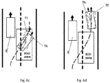
- FIG. 6a-6d Another exemplary embodiment of how the method of determining the kinematic of a target vehicle T, according to the invention, applies for a specific road scenario is shown in Fig. 6a-6d .
- the road scenario concerned in this case is that of lane changing from a current position of target vehicle T running behind ego vehicle E on the same lane (left lane, to be specific).
- the straight path is chosen as projected path; however, starting with the next cycle the lane changing maneuver is detected, and from the existing data the radius of the followed curve is determined.
- target vehicle T is exactly on the predicted path which is the lane changing path (expressed as F2, as it is more important than the combination of left/right curve path expressing the overtaking maneuver), and as soon as target vehicle T finishes the maneuver, the path is computed correctly on the next lane, according to the method.
Abstract
Description
- The method refers to a method and device of determining a kinematic of a target, especially a vehicle, intended to be used in autonomous driving systems.
- For autonomous or semi-autonomous driving systems, the most important factor for radar systems is to determine correctly and accurately the kinematics data - meaning position, speed and heading - of a moving object set as a target. As radar sensors have a fair amount of noise in the detection of surrounding world, smoothing algorithms (Kalman-filter, polynomial regression, low-pass filter) are used to calculate the target object's parameters. These algorithms reduce the noise coming from the sensor, but the accuracy is never 100%, as a standard deviation always exists.
- Nevertheless, when testing the blind spot detection functionality on its boundaries, for example, it is important to have an almost 100% accuracy - specific test scenarios allow only extremelly small deviations (see "Blind Spot Detection System Confirmation Test for NCAP - Memorandum/Report - NHTSA - 2015-0119-0025"). The test is done by comparing the data coming from a high precision GPS with objects which are exactly at the blind spot detection zone limit and even deviations with 0.1s of late warnings are considered failures.
- On the other side, the current radar hardware does not have such a great precision as a GPS module, and the noise coming from the radar must be reduced. Two degrees deviation in angle may exist in the best zone, this means 0.34m deviation at 10m. The noise can be reduced by Kalman filter to a certain degree, but not totally.
- Furthermore, the standard deviation of absolute heading calculation is even bigger than for position and speed, as it is harder to reduce the noise. If a stricter Kalman filter is used, then the maneuvers of the target object are missed entirely. For example, the absolute heading of a vehicle cannot change more than five degrees from one cycle to another. Moreover, the absolute heading of a vehicle is strictly constant/increases/decreases through a maneuver, it has only one type of change or no change at all. The same goes for acceleration, there is no fluctuation in real world such as in one cycle there is acceleration, in the next deceleration. Still, these fluctuations exist in radar measurement due to the noise the measurement brings, the smaller the noise the smaller the fluctuation, or the measurement is not real. Anyway, the change of parameters as position, heading, speed, acceleration is always simple in normal case scenarios and can be mapped by a set of linear function defined in a Markov-chain.
- In this respect, the Korean patent
KR101402206B1 - Another patent document,
US 5633642 A , discloses a radar method and a corresponding device. The method implies estimating an azimuth angle of each target object from determined variables of distance or range, relative speed and relative acceleration after Kalman filtering and separating out target objects having a physically impossible behavior (tracking and prediction). That is used to determine which target objects are located on a roadway occupied by a vehicle and which are the most dangerous thereof. - Nevertheless, using only smoothing algorithms to reduce the noise, predict and calculate the kinematics of a target object is not enough. In essence, none of the afore-mentioned inventions does not reflect how the objects are moving in the real world.
- Therefore, there is a need for higly increased accuracy on mapping the movement of target objects.
- The object of the invention is to indicate means for accurately determining a kinematic of a moving object set as target, in order to estimate correctly the target path.
- According to the invention, this object is achieved by the subject matters of the independent claims, namely a method and a device of determining a kinematic of a target, as well as a vehicle equipped with such means. Further advantageous developments are the subject matter of the dependent claims.
- According to a first aspect, the invention provides a method of determining a kinematic of a target in relation to an ego vehicle, the method comprising the following steps: selecting the target when it is detected in a predetermined sensing zone; generating a trace of the target based on position, heading, speed and acceleration; predicting a curve the target is taking and calculating a radius of the curve using the generated trace; projecting n paths possible to be followed by the target, expressed as abstract movement functions of a polynomial degree p and using as input the calculated radius and, after having a trace of at least 2p -1 historical points, adding at each further cycle higher probabilities to the paths projected in a previous measuring cycle which are equal with the newly projected ones, and keeping the projected paths, if the radius remains the same as in the previous measuring cycle; computing the current kinematics values by smoothing filter, as predicted kinematics values; comparing the predicted kinematics values with the kinematics values resulted from the projected paths, and determining the final kinematics values.
- According to a second aspect, the invention provides a device of determining a kinematic of a target, which comprises an interface and an evaluation unit. The interface is adapted to receive sensor data related to the target. The evaluation unit is adapted to: predict a curve the target is taking and calculate a radius of the curve using the generated trace; project n paths possible to be followed by the target, expressed as abstract movement functions of a polynomial degree p and using as input the calculated radius, after having a trace of at least 2p -1 historical points; at each further cycle, add higher probabilities to the paths projected in a previous measuring cycle which are equal with the newly projected ones and keep the projected paths, if the radius remains the same as in the previous measuring cycle; compute the current kinematics values using an smoothing algorithm, as predicted kinematics values; compare the predicted kinematics values with the kinematics values resulted from the projected paths, and determine the final kinematics data values.
- According to a third aspect, the invention provides a vehicle equipped with a sensor system adapted to provide sensor data of surrounding of the ego vehicle, and a driving assistance system, able to receive signals from a device of determining a kinematic of a target.
- According to the invention, a most probable path of a target vehicle is accurately chosen after comparing a predicted path with a projected path. Having this projected path, more precise kinematics values are computed for each of the two implied vehicles, so the method performs data validation in real-time. By doing this, almost all the noise coming from sensors can be eliminated, at least in usual, normal situations. Furthermore, as those projected paths are abstract models which reflect reality, further positions and movement of target can be predicted with higher precision.
- The method also contributes to a better performance for advanced driving functions, like blind spot detection, lane change assist, front/rear traffic cross alert and so on.
- According to an embodiment of the method, the step of determining the final kinematics values comprises the condition that, if the standard deviation of the kinematics values associated to the projected paths is close to the standard deviation of the kinematics values associated to the predicted paths, then the kinematic parameters are those associated to the projected paths, otherwise the kinematics values are those associated with the predicted paths.
- According to particular embodiment of the method, the abstract movement functions are defined as Markov-chain matrices.
- According to another embodiment of the method, the radius of the curve taken by the target is obtained by polynomial regression, using the generated trace.
- According to another particular embodiment of the method, the smoothing filter used to compute the kinematics values associated to predicted paths is a Kalman filter.
- According to another particular embodiment of the method, the smoothing filter used to compute the kinematics values associated to predicted paths is a low-pass filter.
- According to a preferred embodiment of the device, the evaluation unit is adapted to define the abstract movement functions as Markov-chain matrices.
- According to another embodiment of the device, the evaluation unit is adapted to output the determined kinematics data to a driving assistance system, in order to assist functions like blind spot detection, lane change support, front and rear traffic cross alert.
- For a more complete understanding of the invention and the advantages thereof, exemplary embodiments of the invention are explained in more detail in the following description with reference to the attached figures, in which similar reference numbers designate similar parts. The figures show:
-
Fig. 1 - a schematic block diagram of a device of determining a kinematic of a target vehicle, according to an embodiment of the invention; -
Fig. 2 - a schematic block diagram of a vehicle equipped with a device according to an embodiment of the invention; -
Fig. 3a-3d - an illustrative example of a first road scenario with a target vehicle going straight with constant speed at a certain distance behind an ego vehicle, and how measurement errors could influence the detection of the target vehicle in the blind spot detection zone against the actual position; -
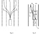
Fig. 4 - an illustration of the possible maneuvers to be followed by a vehicle while running on a highway; -
Fig. 5 - an example of actual position of a straight-going target vehicle, calculated according to the method; -
Fig. 6a-6d - examples of actual heading and position of a target vehicle changing lanes, calculated according to the method, in comparison with the heading and positions computed by using Kalman-filter; -
Fig. 7 - a flowchart of a method of determining a kinematic of a target, according to the invention. -
Fig. 1 shows a schematic block diagram of adevice 1 of determining a kinematic of a target T. Target T can be, in the context of the invention, a motorized traffic participant (described as a rectangle), such as a motor vehicle, a motorcycle/bicycle or alike. - A schematic view of an ego vehicle E equipped with such a
device 1 and with asensing system 2, as well as adriving assistance system 5 is illustrated inFig. 2 . - The
device 1 comprises aninterface 4 which is adapted to receive input data from any active form of remote sensing, such as radar, lidar, optic, ultrasonic or infrared sensors, for example, as well as GPS sensors. The received input data are related to a target external to said ego vehicle E, the target T being present in a predetermined scanning zone of thesensing system 2. In order to facilitate the understanding of the invention, the traffic participant designated as target T in this description is a vehicle whose direction (angle) of movement over ground has been detected and history of measurement positions has been generated as a trace. - Further on, the
device 1 comprises anevaluation unit 3 adapted to use input data extracted from the trace of path and positions, and to further determine a kinematic of target T according to the method which is described in detail in the following section. - In order to illustrate the way target vehicle T is perceived by
sensing systems 2,Fig. 3a shows an actual position of target vehicle T at the limit of the blind spot detection zone of ego vehicle E, for example, whileFig. 3b-3d show how the measurement errors could influence the detection of target vehicle T in or out the blind detection zone. In this first road scenario target vehicle T is going straight with constant speed at a certain distance behind ego vehicle E, so there are absolute no fluctuations of kinematic parameters from one cycle to another, even the position of target vehicle T relative to ego vehicle E remains the same. However, due to the measurement noise, a current algorithm (Kalman filter, for example) will compute slight deviations in heading, position, speed, acceleration and so on. Even small fluctuations are enough to wrongly put target vehicle T in the blind spot detection zone, for example (seeFig. 3b ,3d ), and give an alarm. - It is of interest, for the purpose of this invention, to discuss the cases requiring to map the kinematic parameters to a set of functions which reflect the reality. In reality there is noise in the motion of a vehicle; while driving, in 99% of the cases, the usual situation is that only simple movements are made, having a constant acceleration and a constant direction change. If these movements are expressed by mathematical functions, the exact movement of a target vehicle can be predicted and analyzed.
- The concept consists into projecting at each cycle a set of paths expressed by movement functions of a polynomial degree n (which describe every kinematic parameter and make a Markov-chain model) from the trace and current parameters of target T and choosing the movement function which defines most accurately the actual path of the target, by comparing the projected paths with a path predicted by using existing smoothing algorithms.
- In case none of the projected paths match with the predicted ones, the updated kinematics values from the smoothing algorithms will represent an unusual situation and thus the output data will be the one resulting from the smoothing algorithm. In the end, the goal is to reach a simplified solution where, using a minimal set of parameters, all the other variables/kinematics values to be calculated.
- The set of functions which define the Markov-chain models associated to the kinematic of a vehicle (heading, acceleration, speed and position) comes as follow for a certain maneuver, and period of time t:


- Next comes the simplified model for acceleration, describing a normal behavior, considering how an acceleration pedal is pressed over time, and how the pedal movement modifies the speed of the vehicle - almost linear changes.

- The set of functions serialized, to be used in case of pass-bypass/frame-to-frame computation looks like that:

- For every type of maneuver only the definition of the absolute heading functions differs. This heading function is only a simple first degree polynomial. It is based on observation and mapping of how a normal maneuver is done by a vehicle. For a better understanding of how this normal maneuvers are mathematically described,
Fig. 4 shows five possible paths, expressed as functions F1,...,F5, respectively: - Functions F1 and F5 describing constant turning to left/right are expressed by the following Markov-chain:

- Functions F2 and F4 describing lane changing are expressed by the following Markov-chain:

-
Function 3 describing straight heading is described by the following equation:
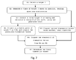
- Further on it comes a preferred embodiment of the method of determining a kinematic of a target, according to the invention, applied for highway driving scenarios. The method algorithm is represented in
Fig. 7 . - The method follows the next steps:
- S1: Select a target T when it is detected in the predetermined sensing zone;
- S2: Generate a trace of the target based on position, heading, speed and acceleration;
- S3: Predict a curve the target is taking and calculating a radius of the curve using the generated trace;
- S4: Project n possible paths of target T as calculated functions ( n =5 in case of highway - see
Fig. 4 ) depending on the calculated radius and compute the associated kinematics values;- S4.0: once the target is selected and a trace of at least five historical points is detected, initialize the n projected paths as calculated functions;
- S4.1: at each further cycle keep projecting the n paths as functions depending on the calculated radius; look at the previously projected paths and add higher probabilities to those which are equal with the newly projected ones;
- S4.2: If the radius is the same as in the previous cycle, then target T is on one of the projected paths;
- S5: Compute current kinematics values using an existing, usual algorithm (Kalman filter, low pass filter etc.);
- S6: Compare the kinematics values calculated by the existing, usual algorithm with the kinematics values resulted from the projected paths from step S4;
- S7: Determine the final kinematics values:
- S7.1. If the standard deviation of the kinematics values associated to projected paths is close to the standard deviation of the kinematics values associated to predicted paths, then the kinematic parameters will be equal to the output of the projected path (as function) - eliminating all the noise;
- S7.2. If the deviation of any of the paths is high, than use the kinematics values from the usual algorithm.
-
Fig. 5a shows an examplary embodiment on how the method of determining a kinematic of a target, according to the invention, computes the actual position of a straight-going target vehicle T on a two lanes highway, a right lane and a left lane, respectively, in comparison with the position predicted by using Kalman-filter in global coordinates. Target vehicle T is running on the right lane, while ego vehicle E is running on the left lane. There are illustrated (seeFig. 5b-5d ) three possible positions of target T behind ego vehicle E at the limit of the blind spot detection zone of ego vehicle E (meaning 12.1m in axial direction and 3m in transversal direction), as perceived according to the sensor data after Kalman filtering. Target vehicle T position as predicted by Kalman filter is illustrated by a rectangle Tk comprising the afferent cluster of points joined by lines (Fig. 5a ), while the actual position of target vehicle T, computed correctly after matching with afferent movement functions, is shown by a dotted rectangle Tf situated in the middle of the right lane. F1 is the function expressing the straight heading path of target vehicle T, F2 is the function expressing the lane changing path of target vehicle T, by turning left. - Target vehicle T is considered as having constant speed behind the ego vehicle E, the same speed as ego vehicle E. In this case, there are absolutely no fluctuations of kinematic parameters from one cycle to another, even the position of target vehicle T relative to ego vehicle E remains the same. The radius as extracted from the trace is calculated as being almost zero. By using polynomial regression, speed and acceleration are determined as constant as well, so there is no acceleration, only constant speed. A number of n paths which could be followed by target vehicle T as normal maneuvers are created as abstract movement functions (in this case two, namely F1 - heading straight ahead and F2 - lane changing), and the associated kinematics values are computed. Also, current values of kinematics are computed using the existing, normal algorithms (Kalman filter, low pass filter etc.) and compared with the kinematics values associated to the respective functions (projected paths). In the end, the chosen path will be the one of constant absolute heading, since it have the highest probability to be followed by target vehicle T. In this manner, speed, position, heading, acceleration is computed 100% correctly and accurately, eliminating all the noise and, most important, no warning is triggered.
- Another exemplary embodiment of how the method of determining the kinematic of a target vehicle T, according to the invention, applies for a specific road scenario is shown in
Fig. 6a-6d . The road scenario concerned in this case is that of lane changing from a current position of target vehicle T running behind ego vehicle E on the same lane (left lane, to be specific). - In this case, in the first cycle, as the Kalman filter predicts target vehicle T is going straight, the straight path is chosen as projected path; however, starting with the next cycle the lane changing maneuver is detected, and from the existing data the radius of the followed curve is determined. For the next few cycles target vehicle T is exactly on the predicted path which is the lane changing path (expressed as F2, as it is more important than the combination of left/right curve path expressing the overtaking maneuver), and as soon as target vehicle T finishes the maneuver, the path is computed correctly on the next lane, according to the method.
- While certain embodiments of the present invention have been described in detail, those familiar with the art to which this invention relates will recognize various alternative designs and embodiments for practicing the invention as defined by the following claims.
-
- 1
- device
- 2
- sensing system
- 3
- interface
- 4
- evaluation unit
- 5
- driving assistance system
- E
- ego vehicle
- F1-F5
- paths projected as functions
- T
- target
- Tk
- target predicted by Kalman filter
- Tf
- target as computed by functions
Claims (10)
- A method of determining a kinematic of a target in relation to an ego vehicle, the method comprising the following steps:- (S1) selecting the target when it is detected in a predetermined sensing zone;- (S2) generating a trace of the target based on position, heading, speed and acceleration;- (S3) predicting a curve the target is taking and calculating a radius of the curve using the generated trace;- (S4) projecting n target paths created as abstract movement functions of a polynomial degree p depending on the calculated radius, after having a trace of at least 2p -1 historical points; at each further cycle, adding higher probabilities to the paths projected in a previous measuring cycle which are equal with the newly projected ones and keeping the projected paths, if the radius remains the same as in the previous measuring cycle;- (S5) computing the current kinematics values by smoothing filter, as predicted kinematics values;- (S6) comparing the predicted kinematics values with the kinematics values resulted from the projected paths, and- (S7) determining the final kinematics values.
- Method according to claim 1, characterized by that the step (S7) of determining the final kinematics values comprises (S7.1) if the standard deviation of the kinematics values associated to the projected paths is close to the standard deviation of the kinematics values associated to the predicted paths, then the kinematic parameters are those associated to the projected paths, otherwise (S7.2) use the kinematics values associated to the predicted paths.
- Method according to claim 1, characterized in that comprises defining the abstract movement functions as Markov-chain matrices.
- Method according to claim 1, characterized in that the radius of the curve taken by target is obtained by polynomial regression using the generated trace.
- Method according to claim 1, characterized in that the smoothing filter used to compute the kinematics values associated to predicted paths is a Kalman filter.
- Method according to claim 1, characterized in that the smoothing filter used to compute the kinematics values associated to predicted paths is a low-pass filter.
- A device (1) of determining a kinematic of a target, comprising:- an interface (3) adapted to receive sensor data related to the target, as well as ego vehicle kinematics data such as heading, position, speed and acceleration;- an evaluation unit (4) adapted:∘ to predict a curve the target is taking and calculate a radius of the curve using the generated trace;∘ to project n target paths expressed as abstract movement functions of a polynomial degree p depending on the calculated radius, after having a trace of at least 2p -1 historical points; at each further cycle, to add higher probabilities to the paths projected in a previous measuring cycle which are equal with the newly projected ones and to keep the projected paths, if the radius remains the same as in the previous measuring cycle;∘ to compute the current kinematics values using an smoothing algorithm, as predicted kinematics values;∘ to compare the predicted kinematics values with the kinematics values resulted from the projected paths, and determine the final kinematics values.
- Device according to claim 7, characterized in that the evaluation unit (4) is adapted to define the abstract movement functions as Markov-chain matrices.
- Device according to claim 8, characterized in that the evaluation unit (4) is adapted to output the determined kinematics data to a driving assistance system (5), as to assist functions like blind spot detection, lane change support, front and rear traffic cross alert.
- A vehicle eqquiped with a sensor system (2) adapted to provide sensor data of surroundings of the ego vehicle, and a driving assistance system (5) able to receive signals from a device according to any of the claims 7 to 9.
Priority Applications (3)
| Application Number | Priority Date | Filing Date | Title |
|---|---|---|---|
| EP17465565.4A EP3477333B1 (en) | 2017-10-26 | 2017-10-26 | Method and device of determining kinematics of a target |
| PCT/EP2018/073947 WO2019081108A1 (en) | 2017-10-26 | 2018-09-06 | Method and device of determining kinematics of a target |
| US16/858,497 US11458966B2 (en) | 2017-10-26 | 2020-04-24 | Method and device of determining kinematics of a target |
Applications Claiming Priority (1)
| Application Number | Priority Date | Filing Date | Title |
|---|---|---|---|
| EP17465565.4A EP3477333B1 (en) | 2017-10-26 | 2017-10-26 | Method and device of determining kinematics of a target |
Publications (2)
| Publication Number | Publication Date |
|---|---|
| EP3477333A1 true EP3477333A1 (en) | 2019-05-01 |
| EP3477333B1 EP3477333B1 (en) | 2023-08-09 |
Family
ID=60515298
Family Applications (1)
| Application Number | Title | Priority Date | Filing Date |
|---|---|---|---|
| EP17465565.4A Active EP3477333B1 (en) | 2017-10-26 | 2017-10-26 | Method and device of determining kinematics of a target |
Country Status (3)
| Country | Link |
|---|---|
| US (1) | US11458966B2 (en) |
| EP (1) | EP3477333B1 (en) |
| WO (1) | WO2019081108A1 (en) |
Cited By (2)
| Publication number | Priority date | Publication date | Assignee | Title |
|---|---|---|---|---|
| CN110304075A (en) * | 2019-07-04 | 2019-10-08 | 清华大学 | Track of vehicle prediction technique based on Mix-state DBN and Gaussian process |
| CN114527796A (en) * | 2022-02-25 | 2022-05-24 | 国网山东省电力公司临沂供电公司 | Method and system for unmanned aerial vehicle to fly by imitating power transmission line |
Families Citing this family (2)
| Publication number | Priority date | Publication date | Assignee | Title |
|---|---|---|---|---|
| US11378956B2 (en) * | 2018-04-03 | 2022-07-05 | Baidu Usa Llc | Perception and planning collaboration framework for autonomous driving |
| CN115358530A (en) * | 2022-07-26 | 2022-11-18 | 上海交通大学 | Vehicle-road cooperative sensing roadside test data quality evaluation method |
Citations (4)
| Publication number | Priority date | Publication date | Assignee | Title |
|---|---|---|---|---|
| US5633642A (en) | 1993-11-23 | 1997-05-27 | Siemens Aktiengesellschaft | Radar method and device for carrying out the method |
| US20100017180A1 (en) * | 2006-12-05 | 2010-01-21 | Martin Randler | Method and device for object tracking in a driver assistance system of a motor vehicle |
| KR101402206B1 (en) | 2014-04-10 | 2014-05-30 | 국방과학연구소 | Multiple target tracking method with kinematics and feature information of targets |
| DE102016206550A1 (en) * | 2016-04-19 | 2017-10-19 | Conti Temic Microelectronic Gmbh | Device and method for determining an object kinematics of a moving object |
Family Cites Families (6)
| Publication number | Priority date | Publication date | Assignee | Title |
|---|---|---|---|---|
| DE60123640T2 (en) * | 2000-09-08 | 2007-08-16 | Raytheon Company, Waltham | METHOD AND DEVICE FOR PREDICTION OF A PATH |
| US6826479B2 (en) * | 2002-06-03 | 2004-11-30 | Visteon Global Technologies, Inc. | Method and apparatus for target vehicle identification in automatic cruise control and collision avoidance systems |
| US7102496B1 (en) * | 2002-07-30 | 2006-09-05 | Yazaki North America, Inc. | Multi-sensor integration for a vehicle |
| US8384531B2 (en) * | 2009-04-02 | 2013-02-26 | GM Global Technology Operations LLC | Recommended following distance on full-windshield head-up display |
| EP2637072B1 (en) * | 2012-03-05 | 2017-10-11 | Volvo Car Corporation | Path following of a target vehicle |
| CN104269070B (en) * | 2014-08-20 | 2017-05-17 | 东风汽车公司 | Active vehicle safety pre-warning method and safety pre-warning system with same applied |
-
2017
- 2017-10-26 EP EP17465565.4A patent/EP3477333B1/en active Active
-
2018
- 2018-09-06 WO PCT/EP2018/073947 patent/WO2019081108A1/en active Application Filing
-
2020
- 2020-04-24 US US16/858,497 patent/US11458966B2/en active Active
Patent Citations (4)
| Publication number | Priority date | Publication date | Assignee | Title |
|---|---|---|---|---|
| US5633642A (en) | 1993-11-23 | 1997-05-27 | Siemens Aktiengesellschaft | Radar method and device for carrying out the method |
| US20100017180A1 (en) * | 2006-12-05 | 2010-01-21 | Martin Randler | Method and device for object tracking in a driver assistance system of a motor vehicle |
| KR101402206B1 (en) | 2014-04-10 | 2014-05-30 | 국방과학연구소 | Multiple target tracking method with kinematics and feature information of targets |
| DE102016206550A1 (en) * | 2016-04-19 | 2017-10-19 | Conti Temic Microelectronic Gmbh | Device and method for determining an object kinematics of a moving object |
Non-Patent Citations (1)
| Title |
|---|
| LI X R ET AL: "Survey of Maneuvering Target Tracking. Part 1: Dynamic Models", IEEE TRANSACTIONS ON AEROSPACE AND ELECTRONIC SYSTEMS, IEEE SERVICE CENTER, PISCATAWAY, NJ, US, vol. 39, no. 4, 1 October 2003 (2003-10-01), pages 1333 - 1364, XP003003342, ISSN: 0018-9251, DOI: 10.1109/TAES.2003.1261132 * |
Cited By (2)
| Publication number | Priority date | Publication date | Assignee | Title |
|---|---|---|---|---|
| CN110304075A (en) * | 2019-07-04 | 2019-10-08 | 清华大学 | Track of vehicle prediction technique based on Mix-state DBN and Gaussian process |
| CN114527796A (en) * | 2022-02-25 | 2022-05-24 | 国网山东省电力公司临沂供电公司 | Method and system for unmanned aerial vehicle to fly by imitating power transmission line |
Also Published As
| Publication number | Publication date |
|---|---|
| US11458966B2 (en) | 2022-10-04 |
| EP3477333B1 (en) | 2023-08-09 |
| WO2019081108A1 (en) | 2019-05-02 |
| US20200255006A1 (en) | 2020-08-13 |
Similar Documents
| Publication | Publication Date | Title |
|---|---|---|
| KR101786237B1 (en) | Apparatus and method for processing failure detection and calibration of sensor in driver assist system | |
| US11458966B2 (en) | Method and device of determining kinematics of a target | |
| US9937905B2 (en) | Side collision avoidance system and method for vehicle | |
| CN106257242B (en) | Unit and method for adjusting road boundaries | |
| EP3640890B1 (en) | Systems and methods for braking a vehicle based on a detected object | |
| US10741079B2 (en) | Route prediction system | |
| US7729857B2 (en) | System for and method of detecting a collision and predicting a vehicle path | |
| JP6256531B2 (en) | Object recognition processing device, object recognition processing method, and automatic driving system | |
| US6903677B2 (en) | Collision prediction device, method of predicting collision, and computer product | |
| US20180059679A1 (en) | Depth map estimation with stereo images | |
| US20200369293A1 (en) | Autonomous driving apparatus and method | |
| US20220169280A1 (en) | Method and Device for Multi-Sensor Data Fusion For Automated and Autonomous Vehicles | |
| JP6838241B2 (en) | Mobile behavior prediction device | |
| US11390288B2 (en) | Other-vehicle action prediction method and other-vehicle action prediction device | |
| EP3456596A1 (en) | Method and device of predicting a possible collision | |
| JP6558214B2 (en) | Automatic driving device | |
| EP3855205A1 (en) | Perception performance evaluation of a vehicle adas or ads | |
| US20180164833A1 (en) | Autonomous vehicle object detection | |
| US11295609B1 (en) | Travel assistance method and travel assistance device | |
| US20220314984A1 (en) | Vehicle Control Device, Vehicle Control Method, Vehicle Motion Control System, and Lane Estimation Device | |
| US20210366274A1 (en) | Method and device for predicting the trajectory of a traffic participant, and sensor system | |
| US20230182722A1 (en) | Collision avoidance method and apparatus | |
| KR20200133122A (en) | Apparatus and method for preventing vehicle collision | |
| US20220024467A1 (en) | Method for predicting a driving maneuver in a driver assistance system | |
| US20220227386A1 (en) | Vehicle control system |
Legal Events
| Date | Code | Title | Description |
|---|---|---|---|
| PUAI | Public reference made under article 153(3) epc to a published international application that has entered the european phase |
Free format text: ORIGINAL CODE: 0009012 |
|
| STAA | Information on the status of an ep patent application or granted ep patent |
Free format text: STATUS: THE APPLICATION HAS BEEN PUBLISHED |
|
| AK | Designated contracting states |
Kind code of ref document: A1 Designated state(s): AL AT BE BG CH CY CZ DE DK EE ES FI FR GB GR HR HU IE IS IT LI LT LU LV MC MK MT NL NO PL PT RO RS SE SI SK SM TR |
|
| AX | Request for extension of the european patent |
Extension state: BA ME |
|
| STAA | Information on the status of an ep patent application or granted ep patent |
Free format text: STATUS: REQUEST FOR EXAMINATION WAS MADE |
|
| 17P | Request for examination filed |
Effective date: 20191104 |
|
| RBV | Designated contracting states (corrected) |
Designated state(s): AL AT BE BG CH CY CZ DE DK EE ES FI FR GB GR HR HU IE IS IT LI LT LU LV MC MK MT NL NO PL PT RO RS SE SI SK SM TR |
|
| STAA | Information on the status of an ep patent application or granted ep patent |
Free format text: STATUS: EXAMINATION IS IN PROGRESS |
|
| 17Q | First examination report despatched |
Effective date: 20210708 |
|
| STAA | Information on the status of an ep patent application or granted ep patent |
Free format text: STATUS: EXAMINATION IS IN PROGRESS |
|
| RAP1 | Party data changed (applicant data changed or rights of an application transferred) |
Owner name: CONTINENTAL AUTONOMOUS MOBILITY GERMANY GMBH |
|
| GRAP | Despatch of communication of intention to grant a patent |
Free format text: ORIGINAL CODE: EPIDOSNIGR1 |
|
| STAA | Information on the status of an ep patent application or granted ep patent |
Free format text: STATUS: GRANT OF PATENT IS INTENDED |
|
| RIC1 | Information provided on ipc code assigned before grant |
Ipc: G08G 1/16 20060101ALN20230217BHEP Ipc: B60W 50/14 20120101ALN20230217BHEP Ipc: B60W 50/00 20060101ALI20230217BHEP Ipc: B60W 30/18 20060101ALI20230217BHEP Ipc: B60W 30/095 20120101ALI20230217BHEP Ipc: G01S 13/72 20060101AFI20230217BHEP |
|
| INTG | Intention to grant announced |
Effective date: 20230322 |
|
| GRAS | Grant fee paid |
Free format text: ORIGINAL CODE: EPIDOSNIGR3 |
|
| GRAA | (expected) grant |
Free format text: ORIGINAL CODE: 0009210 |
|
| STAA | Information on the status of an ep patent application or granted ep patent |
Free format text: STATUS: THE PATENT HAS BEEN GRANTED |
|
| AK | Designated contracting states |
Kind code of ref document: B1 Designated state(s): AL AT BE BG CH CY CZ DE DK EE ES FI FR GB GR HR HU IE IS IT LI LT LU LV MC MK MT NL NO PL PT RO RS SE SI SK SM TR |
|
| REG | Reference to a national code |
Ref country code: GB Ref legal event code: FG4D |
|
| REG | Reference to a national code |
Ref country code: CH Ref legal event code: EP |
|
| REG | Reference to a national code |
Ref country code: IE Ref legal event code: FG4D |
|
| REG | Reference to a national code |
Ref country code: DE Ref legal event code: R096 Ref document number: 602017072406 Country of ref document: DE |
|
| REG | Reference to a national code |
Ref country code: LT Ref legal event code: MG9D |
|
| REG | Reference to a national code |
Ref country code: NL Ref legal event code: MP Effective date: 20230809 |
|
| REG | Reference to a national code |
Ref country code: AT Ref legal event code: MK05 Ref document number: 1598155 Country of ref document: AT Kind code of ref document: T Effective date: 20230809 |
|
| PG25 | Lapsed in a contracting state [announced via postgrant information from national office to epo] |
Ref country code: GR Free format text: LAPSE BECAUSE OF FAILURE TO SUBMIT A TRANSLATION OF THE DESCRIPTION OR TO PAY THE FEE WITHIN THE PRESCRIBED TIME-LIMIT Effective date: 20231110 |
|
| PG25 | Lapsed in a contracting state [announced via postgrant information from national office to epo] |
Ref country code: IS Free format text: LAPSE BECAUSE OF FAILURE TO SUBMIT A TRANSLATION OF THE DESCRIPTION OR TO PAY THE FEE WITHIN THE PRESCRIBED TIME-LIMIT Effective date: 20231209 |
|
| PG25 | Lapsed in a contracting state [announced via postgrant information from national office to epo] |
Ref country code: SE Free format text: LAPSE BECAUSE OF FAILURE TO SUBMIT A TRANSLATION OF THE DESCRIPTION OR TO PAY THE FEE WITHIN THE PRESCRIBED TIME-LIMIT Effective date: 20230809 Ref country code: RS Free format text: LAPSE BECAUSE OF FAILURE TO SUBMIT A TRANSLATION OF THE DESCRIPTION OR TO PAY THE FEE WITHIN THE PRESCRIBED TIME-LIMIT Effective date: 20230809 Ref country code: PT Free format text: LAPSE BECAUSE OF FAILURE TO SUBMIT A TRANSLATION OF THE DESCRIPTION OR TO PAY THE FEE WITHIN THE PRESCRIBED TIME-LIMIT Effective date: 20231211 Ref country code: NO Free format text: LAPSE BECAUSE OF FAILURE TO SUBMIT A TRANSLATION OF THE DESCRIPTION OR TO PAY THE FEE WITHIN THE PRESCRIBED TIME-LIMIT Effective date: 20231109 Ref country code: NL Free format text: LAPSE BECAUSE OF FAILURE TO SUBMIT A TRANSLATION OF THE DESCRIPTION OR TO PAY THE FEE WITHIN THE PRESCRIBED TIME-LIMIT Effective date: 20230809 Ref country code: LV Free format text: LAPSE BECAUSE OF FAILURE TO SUBMIT A TRANSLATION OF THE DESCRIPTION OR TO PAY THE FEE WITHIN THE PRESCRIBED TIME-LIMIT Effective date: 20230809 Ref country code: LT Free format text: LAPSE BECAUSE OF FAILURE TO SUBMIT A TRANSLATION OF THE DESCRIPTION OR TO PAY THE FEE WITHIN THE PRESCRIBED TIME-LIMIT Effective date: 20230809 Ref country code: IS Free format text: LAPSE BECAUSE OF FAILURE TO SUBMIT A TRANSLATION OF THE DESCRIPTION OR TO PAY THE FEE WITHIN THE PRESCRIBED TIME-LIMIT Effective date: 20231209 Ref country code: HR Free format text: LAPSE BECAUSE OF FAILURE TO SUBMIT A TRANSLATION OF THE DESCRIPTION OR TO PAY THE FEE WITHIN THE PRESCRIBED TIME-LIMIT Effective date: 20230809 Ref country code: GR Free format text: LAPSE BECAUSE OF FAILURE TO SUBMIT A TRANSLATION OF THE DESCRIPTION OR TO PAY THE FEE WITHIN THE PRESCRIBED TIME-LIMIT Effective date: 20231110 Ref country code: FI Free format text: LAPSE BECAUSE OF FAILURE TO SUBMIT A TRANSLATION OF THE DESCRIPTION OR TO PAY THE FEE WITHIN THE PRESCRIBED TIME-LIMIT Effective date: 20230809 Ref country code: AT Free format text: LAPSE BECAUSE OF FAILURE TO SUBMIT A TRANSLATION OF THE DESCRIPTION OR TO PAY THE FEE WITHIN THE PRESCRIBED TIME-LIMIT Effective date: 20230809 |
|
| PGFP | Annual fee paid to national office [announced via postgrant information from national office to epo] |
Ref country code: DE Payment date: 20231031 Year of fee payment: 7 |
|
| PG25 | Lapsed in a contracting state [announced via postgrant information from national office to epo] |
Ref country code: PL Free format text: LAPSE BECAUSE OF FAILURE TO SUBMIT A TRANSLATION OF THE DESCRIPTION OR TO PAY THE FEE WITHIN THE PRESCRIBED TIME-LIMIT Effective date: 20230809 |