EP3477331B1 - Below-noise after transmit (bat) chirp radar - Google Patents
Below-noise after transmit (bat) chirp radar Download PDFInfo
- Publication number
- EP3477331B1 EP3477331B1 EP18194748.2A EP18194748A EP3477331B1 EP 3477331 B1 EP3477331 B1 EP 3477331B1 EP 18194748 A EP18194748 A EP 18194748A EP 3477331 B1 EP3477331 B1 EP 3477331B1
- Authority
- EP
- European Patent Office
- Prior art keywords
- reservoir
- time
- noised
- signal
- varying
- Prior art date
- Legal status (The legal status is an assumption and is not a legal conclusion. Google has not performed a legal analysis and makes no representation as to the accuracy of the status listed.)
- Active
Links
Images


Classifications
-
- G—PHYSICS
- G01—MEASURING; TESTING
- G01S—RADIO DIRECTION-FINDING; RADIO NAVIGATION; DETERMINING DISTANCE OR VELOCITY BY USE OF RADIO WAVES; LOCATING OR PRESENCE-DETECTING BY USE OF THE REFLECTION OR RERADIATION OF RADIO WAVES; ANALOGOUS ARRANGEMENTS USING OTHER WAVES
- G01S7/00—Details of systems according to groups G01S13/00, G01S15/00, G01S17/00
- G01S7/02—Details of systems according to groups G01S13/00, G01S15/00, G01S17/00 of systems according to group G01S13/00
- G01S7/28—Details of pulse systems
- G01S7/285—Receivers
- G01S7/292—Extracting wanted echo-signals
- G01S7/2921—Extracting wanted echo-signals based on data belonging to one radar period
-
- G—PHYSICS
- G01—MEASURING; TESTING
- G01S—RADIO DIRECTION-FINDING; RADIO NAVIGATION; DETERMINING DISTANCE OR VELOCITY BY USE OF RADIO WAVES; LOCATING OR PRESENCE-DETECTING BY USE OF THE REFLECTION OR RERADIATION OF RADIO WAVES; ANALOGOUS ARRANGEMENTS USING OTHER WAVES
- G01S13/00—Systems using the reflection or reradiation of radio waves, e.g. radar systems; Analogous systems using reflection or reradiation of waves whose nature or wavelength is irrelevant or unspecified
- G01S13/003—Bistatic radar systems; Multistatic radar systems
-
- G—PHYSICS
- G01—MEASURING; TESTING
- G01S—RADIO DIRECTION-FINDING; RADIO NAVIGATION; DETERMINING DISTANCE OR VELOCITY BY USE OF RADIO WAVES; LOCATING OR PRESENCE-DETECTING BY USE OF THE REFLECTION OR RERADIATION OF RADIO WAVES; ANALOGOUS ARRANGEMENTS USING OTHER WAVES
- G01S13/00—Systems using the reflection or reradiation of radio waves, e.g. radar systems; Analogous systems using reflection or reradiation of waves whose nature or wavelength is irrelevant or unspecified
- G01S13/02—Systems using reflection of radio waves, e.g. primary radar systems; Analogous systems
- G01S13/0209—Systems with very large relative bandwidth, i.e. larger than 10 %, e.g. baseband, pulse, carrier-free, ultrawideband
-
- G—PHYSICS
- G01—MEASURING; TESTING
- G01S—RADIO DIRECTION-FINDING; RADIO NAVIGATION; DETERMINING DISTANCE OR VELOCITY BY USE OF RADIO WAVES; LOCATING OR PRESENCE-DETECTING BY USE OF THE REFLECTION OR RERADIATION OF RADIO WAVES; ANALOGOUS ARRANGEMENTS USING OTHER WAVES
- G01S13/00—Systems using the reflection or reradiation of radio waves, e.g. radar systems; Analogous systems using reflection or reradiation of waves whose nature or wavelength is irrelevant or unspecified
- G01S13/02—Systems using reflection of radio waves, e.g. primary radar systems; Analogous systems
- G01S13/06—Systems determining position data of a target
- G01S13/08—Systems for measuring distance only
- G01S13/10—Systems for measuring distance only using transmission of interrupted, pulse modulated waves
- G01S13/26—Systems for measuring distance only using transmission of interrupted, pulse modulated waves wherein the transmitted pulses use a frequency- or phase-modulated carrier wave
- G01S13/28—Systems for measuring distance only using transmission of interrupted, pulse modulated waves wherein the transmitted pulses use a frequency- or phase-modulated carrier wave with time compression of received pulses
- G01S13/282—Systems for measuring distance only using transmission of interrupted, pulse modulated waves wherein the transmitted pulses use a frequency- or phase-modulated carrier wave with time compression of received pulses using a frequency modulated carrier wave
-
- G—PHYSICS
- G01—MEASURING; TESTING
- G01S—RADIO DIRECTION-FINDING; RADIO NAVIGATION; DETERMINING DISTANCE OR VELOCITY BY USE OF RADIO WAVES; LOCATING OR PRESENCE-DETECTING BY USE OF THE REFLECTION OR RERADIATION OF RADIO WAVES; ANALOGOUS ARRANGEMENTS USING OTHER WAVES
- G01S13/00—Systems using the reflection or reradiation of radio waves, e.g. radar systems; Analogous systems using reflection or reradiation of waves whose nature or wavelength is irrelevant or unspecified
- G01S13/02—Systems using reflection of radio waves, e.g. primary radar systems; Analogous systems
- G01S13/06—Systems determining position data of a target
- G01S13/08—Systems for measuring distance only
- G01S13/32—Systems for measuring distance only using transmission of continuous waves, whether amplitude-, frequency-, or phase-modulated, or unmodulated
- G01S13/34—Systems for measuring distance only using transmission of continuous waves, whether amplitude-, frequency-, or phase-modulated, or unmodulated using transmission of continuous, frequency-modulated waves while heterodyning the received signal, or a signal derived therefrom, with a locally-generated signal related to the contemporaneously transmitted signal
- G01S13/343—Systems for measuring distance only using transmission of continuous waves, whether amplitude-, frequency-, or phase-modulated, or unmodulated using transmission of continuous, frequency-modulated waves while heterodyning the received signal, or a signal derived therefrom, with a locally-generated signal related to the contemporaneously transmitted signal using sawtooth modulation
-
- G—PHYSICS
- G01—MEASURING; TESTING
- G01S—RADIO DIRECTION-FINDING; RADIO NAVIGATION; DETERMINING DISTANCE OR VELOCITY BY USE OF RADIO WAVES; LOCATING OR PRESENCE-DETECTING BY USE OF THE REFLECTION OR RERADIATION OF RADIO WAVES; ANALOGOUS ARRANGEMENTS USING OTHER WAVES
- G01S13/00—Systems using the reflection or reradiation of radio waves, e.g. radar systems; Analogous systems using reflection or reradiation of waves whose nature or wavelength is irrelevant or unspecified
- G01S13/74—Systems using reradiation of radio waves, e.g. secondary radar systems; Analogous systems
- G01S13/82—Systems using reradiation of radio waves, e.g. secondary radar systems; Analogous systems wherein continuous-type signals are transmitted
- G01S13/825—Systems using reradiation of radio waves, e.g. secondary radar systems; Analogous systems wherein continuous-type signals are transmitted with exchange of information between interrogator and responder
-
- G—PHYSICS
- G01—MEASURING; TESTING
- G01S—RADIO DIRECTION-FINDING; RADIO NAVIGATION; DETERMINING DISTANCE OR VELOCITY BY USE OF RADIO WAVES; LOCATING OR PRESENCE-DETECTING BY USE OF THE REFLECTION OR RERADIATION OF RADIO WAVES; ANALOGOUS ARRANGEMENTS USING OTHER WAVES
- G01S13/00—Systems using the reflection or reradiation of radio waves, e.g. radar systems; Analogous systems using reflection or reradiation of waves whose nature or wavelength is irrelevant or unspecified
- G01S13/88—Radar or analogous systems specially adapted for specific applications
- G01S13/89—Radar or analogous systems specially adapted for specific applications for mapping or imaging
- G01S13/90—Radar or analogous systems specially adapted for specific applications for mapping or imaging using synthetic aperture techniques, e.g. synthetic aperture radar [SAR] techniques
-
- G—PHYSICS
- G01—MEASURING; TESTING
- G01S—RADIO DIRECTION-FINDING; RADIO NAVIGATION; DETERMINING DISTANCE OR VELOCITY BY USE OF RADIO WAVES; LOCATING OR PRESENCE-DETECTING BY USE OF THE REFLECTION OR RERADIATION OF RADIO WAVES; ANALOGOUS ARRANGEMENTS USING OTHER WAVES
- G01S7/00—Details of systems according to groups G01S13/00, G01S15/00, G01S17/00
- G01S7/02—Details of systems according to groups G01S13/00, G01S15/00, G01S17/00 of systems according to group G01S13/00
- G01S7/03—Details of HF subsystems specially adapted therefor, e.g. common to transmitter and receiver
-
- G—PHYSICS
- G01—MEASURING; TESTING
- G01S—RADIO DIRECTION-FINDING; RADIO NAVIGATION; DETERMINING DISTANCE OR VELOCITY BY USE OF RADIO WAVES; LOCATING OR PRESENCE-DETECTING BY USE OF THE REFLECTION OR RERADIATION OF RADIO WAVES; ANALOGOUS ARRANGEMENTS USING OTHER WAVES
- G01S7/00—Details of systems according to groups G01S13/00, G01S15/00, G01S17/00
- G01S7/02—Details of systems according to groups G01S13/00, G01S15/00, G01S17/00 of systems according to group G01S13/00
- G01S7/28—Details of pulse systems
- G01S7/2813—Means providing a modification of the radiation pattern for cancelling noise, clutter or interfering signals, e.g. side lobe suppression, side lobe blanking, null-steering arrays
-
- G—PHYSICS
- G01—MEASURING; TESTING
- G01S—RADIO DIRECTION-FINDING; RADIO NAVIGATION; DETERMINING DISTANCE OR VELOCITY BY USE OF RADIO WAVES; LOCATING OR PRESENCE-DETECTING BY USE OF THE REFLECTION OR RERADIATION OF RADIO WAVES; ANALOGOUS ARRANGEMENTS USING OTHER WAVES
- G01S7/00—Details of systems according to groups G01S13/00, G01S15/00, G01S17/00
- G01S7/02—Details of systems according to groups G01S13/00, G01S15/00, G01S17/00 of systems according to group G01S13/00
- G01S7/28—Details of pulse systems
- G01S7/285—Receivers
- G01S7/292—Extracting wanted echo-signals
- G01S7/2923—Extracting wanted echo-signals based on data belonging to a number of consecutive radar periods
-
- G—PHYSICS
- G01—MEASURING; TESTING
- G01S—RADIO DIRECTION-FINDING; RADIO NAVIGATION; DETERMINING DISTANCE OR VELOCITY BY USE OF RADIO WAVES; LOCATING OR PRESENCE-DETECTING BY USE OF THE REFLECTION OR RERADIATION OF RADIO WAVES; ANALOGOUS ARRANGEMENTS USING OTHER WAVES
- G01S7/00—Details of systems according to groups G01S13/00, G01S15/00, G01S17/00
- G01S7/02—Details of systems according to groups G01S13/00, G01S15/00, G01S17/00 of systems according to group G01S13/00
- G01S7/28—Details of pulse systems
- G01S7/285—Receivers
- G01S7/295—Means for transforming co-ordinates or for evaluating data, e.g. using computers
- G01S7/2955—Means for determining the position of the radar coordinate system for evaluating the position data of the target in another coordinate system
-
- G—PHYSICS
- G01—MEASURING; TESTING
- G01S—RADIO DIRECTION-FINDING; RADIO NAVIGATION; DETERMINING DISTANCE OR VELOCITY BY USE OF RADIO WAVES; LOCATING OR PRESENCE-DETECTING BY USE OF THE REFLECTION OR RERADIATION OF RADIO WAVES; ANALOGOUS ARRANGEMENTS USING OTHER WAVES
- G01S7/00—Details of systems according to groups G01S13/00, G01S15/00, G01S17/00
- G01S7/02—Details of systems according to groups G01S13/00, G01S15/00, G01S17/00 of systems according to group G01S13/00
- G01S7/35—Details of non-pulse systems
- G01S7/352—Receivers
- G01S7/354—Extracting wanted echo-signals
-
- G—PHYSICS
- G01—MEASURING; TESTING
- G01S—RADIO DIRECTION-FINDING; RADIO NAVIGATION; DETERMINING DISTANCE OR VELOCITY BY USE OF RADIO WAVES; LOCATING OR PRESENCE-DETECTING BY USE OF THE REFLECTION OR RERADIATION OF RADIO WAVES; ANALOGOUS ARRANGEMENTS USING OTHER WAVES
- G01S7/00—Details of systems according to groups G01S13/00, G01S15/00, G01S17/00
- G01S7/02—Details of systems according to groups G01S13/00, G01S15/00, G01S17/00 of systems according to group G01S13/00
- G01S7/41—Details of systems according to groups G01S13/00, G01S15/00, G01S17/00 of systems according to group G01S13/00 using analysis of echo signal for target characterisation; Target signature; Target cross-section
- G01S7/414—Discriminating targets with respect to background clutter
-
- G—PHYSICS
- G01—MEASURING; TESTING
- G01S—RADIO DIRECTION-FINDING; RADIO NAVIGATION; DETERMINING DISTANCE OR VELOCITY BY USE OF RADIO WAVES; LOCATING OR PRESENCE-DETECTING BY USE OF THE REFLECTION OR RERADIATION OF RADIO WAVES; ANALOGOUS ARRANGEMENTS USING OTHER WAVES
- G01S7/00—Details of systems according to groups G01S13/00, G01S15/00, G01S17/00
- G01S7/02—Details of systems according to groups G01S13/00, G01S15/00, G01S17/00 of systems according to group G01S13/00
- G01S7/41—Details of systems according to groups G01S13/00, G01S15/00, G01S17/00 of systems according to group G01S13/00 using analysis of echo signal for target characterisation; Target signature; Target cross-section
- G01S7/417—Details of systems according to groups G01S13/00, G01S15/00, G01S17/00 of systems according to group G01S13/00 using analysis of echo signal for target characterisation; Target signature; Target cross-section involving the use of neural networks
-
- G—PHYSICS
- G01—MEASURING; TESTING
- G01S—RADIO DIRECTION-FINDING; RADIO NAVIGATION; DETERMINING DISTANCE OR VELOCITY BY USE OF RADIO WAVES; LOCATING OR PRESENCE-DETECTING BY USE OF THE REFLECTION OR RERADIATION OF RADIO WAVES; ANALOGOUS ARRANGEMENTS USING OTHER WAVES
- G01S7/00—Details of systems according to groups G01S13/00, G01S15/00, G01S17/00
- G01S7/02—Details of systems according to groups G01S13/00, G01S15/00, G01S17/00 of systems according to group G01S13/00
- G01S7/41—Details of systems according to groups G01S13/00, G01S15/00, G01S17/00 of systems according to group G01S13/00 using analysis of echo signal for target characterisation; Target signature; Target cross-section
- G01S7/418—Theoretical aspects
-
- G—PHYSICS
- G01—MEASURING; TESTING
- G01S—RADIO DIRECTION-FINDING; RADIO NAVIGATION; DETERMINING DISTANCE OR VELOCITY BY USE OF RADIO WAVES; LOCATING OR PRESENCE-DETECTING BY USE OF THE REFLECTION OR RERADIATION OF RADIO WAVES; ANALOGOUS ARRANGEMENTS USING OTHER WAVES
- G01S7/00—Details of systems according to groups G01S13/00, G01S15/00, G01S17/00
- G01S7/52—Details of systems according to groups G01S13/00, G01S15/00, G01S17/00 of systems according to group G01S15/00
- G01S7/52017—Details of systems according to groups G01S13/00, G01S15/00, G01S17/00 of systems according to group G01S15/00 particularly adapted to short-range imaging
- G01S7/52077—Details of systems according to groups G01S13/00, G01S15/00, G01S17/00 of systems according to group G01S15/00 particularly adapted to short-range imaging with means for elimination of unwanted signals, e.g. noise or interference
-
- G—PHYSICS
- G06—COMPUTING OR CALCULATING; COUNTING
- G06F—ELECTRIC DIGITAL DATA PROCESSING
- G06F18/00—Pattern recognition
- G06F18/20—Analysing
- G06F18/21—Design or setup of recognition systems or techniques; Extraction of features in feature space; Blind source separation
- G06F18/213—Feature extraction, e.g. by transforming the feature space; Summarisation; Mappings, e.g. subspace methods
- G06F18/2134—Feature extraction, e.g. by transforming the feature space; Summarisation; Mappings, e.g. subspace methods based on separation criteria, e.g. independent component analysis
-
- G—PHYSICS
- G06—COMPUTING OR CALCULATING; COUNTING
- G06F—ELECTRIC DIGITAL DATA PROCESSING
- G06F18/00—Pattern recognition
- G06F18/20—Analysing
- G06F18/24—Classification techniques
- G06F18/241—Classification techniques relating to the classification model, e.g. parametric or non-parametric approaches
- G06F18/2413—Classification techniques relating to the classification model, e.g. parametric or non-parametric approaches based on distances to training or reference patterns
- G06F18/24133—Distances to prototypes
- G06F18/24143—Distances to neighbourhood prototypes, e.g. restricted Coulomb energy networks [RCEN]
-
- G—PHYSICS
- G06—COMPUTING OR CALCULATING; COUNTING
- G06N—COMPUTING ARRANGEMENTS BASED ON SPECIFIC COMPUTATIONAL MODELS
- G06N3/00—Computing arrangements based on biological models
- G06N3/02—Neural networks
- G06N3/04—Architecture, e.g. interconnection topology
- G06N3/044—Recurrent networks, e.g. Hopfield networks
- G06N3/0442—Recurrent networks, e.g. Hopfield networks characterised by memory or gating, e.g. long short-term memory [LSTM] or gated recurrent units [GRU]
-
- G—PHYSICS
- G06—COMPUTING OR CALCULATING; COUNTING
- G06N—COMPUTING ARRANGEMENTS BASED ON SPECIFIC COMPUTATIONAL MODELS
- G06N3/00—Computing arrangements based on biological models
- G06N3/02—Neural networks
- G06N3/08—Learning methods
- G06N3/084—Backpropagation, e.g. using gradient descent
-
- G—PHYSICS
- G06—COMPUTING OR CALCULATING; COUNTING
- G06N—COMPUTING ARRANGEMENTS BASED ON SPECIFIC COMPUTATIONAL MODELS
- G06N3/00—Computing arrangements based on biological models
- G06N3/02—Neural networks
- G06N3/08—Learning methods
- G06N3/09—Supervised learning
-
- G—PHYSICS
- G01—MEASURING; TESTING
- G01S—RADIO DIRECTION-FINDING; RADIO NAVIGATION; DETERMINING DISTANCE OR VELOCITY BY USE OF RADIO WAVES; LOCATING OR PRESENCE-DETECTING BY USE OF THE REFLECTION OR RERADIATION OF RADIO WAVES; ANALOGOUS ARRANGEMENTS USING OTHER WAVES
- G01S13/00—Systems using the reflection or reradiation of radio waves, e.g. radar systems; Analogous systems using reflection or reradiation of waves whose nature or wavelength is irrelevant or unspecified
- G01S13/87—Combinations of radar systems, e.g. primary radar and secondary radar
- G01S13/878—Combination of several spaced transmitters or receivers of known location for determining the position of a transponder or a reflector
-
- G—PHYSICS
- G01—MEASURING; TESTING
- G01S—RADIO DIRECTION-FINDING; RADIO NAVIGATION; DETERMINING DISTANCE OR VELOCITY BY USE OF RADIO WAVES; LOCATING OR PRESENCE-DETECTING BY USE OF THE REFLECTION OR RERADIATION OF RADIO WAVES; ANALOGOUS ARRANGEMENTS USING OTHER WAVES
- G01S13/00—Systems using the reflection or reradiation of radio waves, e.g. radar systems; Analogous systems using reflection or reradiation of waves whose nature or wavelength is irrelevant or unspecified
- G01S13/88—Radar or analogous systems specially adapted for specific applications
- G01S13/93—Radar or analogous systems specially adapted for specific applications for anti-collision purposes
- G01S13/931—Radar or analogous systems specially adapted for specific applications for anti-collision purposes of land vehicles
-
- G—PHYSICS
- G01—MEASURING; TESTING
- G01S—RADIO DIRECTION-FINDING; RADIO NAVIGATION; DETERMINING DISTANCE OR VELOCITY BY USE OF RADIO WAVES; LOCATING OR PRESENCE-DETECTING BY USE OF THE REFLECTION OR RERADIATION OF RADIO WAVES; ANALOGOUS ARRANGEMENTS USING OTHER WAVES
- G01S13/00—Systems using the reflection or reradiation of radio waves, e.g. radar systems; Analogous systems using reflection or reradiation of waves whose nature or wavelength is irrelevant or unspecified
- G01S13/88—Radar or analogous systems specially adapted for specific applications
- G01S13/93—Radar or analogous systems specially adapted for specific applications for anti-collision purposes
- G01S13/933—Radar or analogous systems specially adapted for specific applications for anti-collision purposes of aircraft or spacecraft
-
- G—PHYSICS
- G06—COMPUTING OR CALCULATING; COUNTING
- G06F—ELECTRIC DIGITAL DATA PROCESSING
- G06F2218/00—Aspects of pattern recognition specially adapted for signal processing
- G06F2218/02—Preprocessing
- G06F2218/04—Denoising
-
- G—PHYSICS
- G06—COMPUTING OR CALCULATING; COUNTING
- G06F—ELECTRIC DIGITAL DATA PROCESSING
- G06F2218/00—Aspects of pattern recognition specially adapted for signal processing
- G06F2218/22—Source localisation; Inverse modelling
Definitions
- the present disclosure relates to radars and radar systems and more particularly to a below-noise after transmit (BAT) Chirp Radar.
- BAT below-noise after transmit
- Detecting below-noise radio frequency (RF) signals involves de-noising the RF signals or radar signals to obtain a useable signal or radar return that can be processed to extract the desired information.
- RF radio frequency
- State-of-the-art systems for measuring the range to targets or terrain over an ultra-wide bandwidth (greater than about 30 Giga Hertz (GHz), enabling high resolution) at long range require high rate analog-to-digital converters (ADCs) and some combination of a high power transmitter or a large antenna aperture.
- ADCs analog-to-digital converters
- Such high-rate ADCs are expensive and consume a substantial amount of power, and due to fundamental physical limits, are not capable of achieving a sampling rate needed to capture an ultra-wide bandwidth as defined above.
- Filter-based methods use filtering to smooth out noise from a signal, but are too simplistic to simultaneously maintain the low-frequency long-term trends of a signal while adapting to the high-frequency abrupt transitions.
- Training-based methods rely on a "dictionary" that models the signals of interest. Such a dictionary must be trained in an offline process, and requires training data that may not be available. In addition, the dictionary often requires a large amount of memory and computation to be stored and leveraged on a platform rendering such methods impractical for applications where small size, weight and fast performance are important characteristics.
- U.S. patent No. 5,402,520 which is considered closest prior art, discusses a neural network method and apparatus for retrieving signals embedded in noise and analysing the retrieved signals, but is silent in particular about the feature of the claimed invention that the de-noised reservoir states define a bank of time-varying filters at a chirp rate, set by a transmit chirp of a RF or radar signal, with the response of the time-varying filters to chirps received at different times being equivalent to a response of a bank of 1-pole infinite impulse response (IIR) filters to different frequencies.
- IIR infinite impulse response
- a radar system is provided as set forth in the appended claims.
- a cognitive radar processor is provided as set forth in the appended claims.
- the embodiments described herein are applicable to radar receivers or radar systems that can perform real-time processing of signals over an ultra-wide bandwidth.
- the exemplary embodiments provide expanded situational awareness, providing the core functionality required for ultra-low latency signal detection and analysis over about a 30 GHz instantaneous bandwidth to enable real-time resource allocation based on the RF environment. This performance can be achieved on computing platforms with orders of magnitude lower size, weight, and power.
- the time-varying reservoir computer described enables rapid de-noising and detection of non-stationary signals such as chirps that are widely used in radar systems on a wide variety of platforms.
- the cognitive radar processor described herein has other application enabling multi-static radar and cognitive radio in low signal-to-noise ratio (SNR) conditions.
- the time-varying reservoir computer is particularly useful to detect and track frequency-modulated continuous wave (FMCW) signals or chirp pulses that are used in a wide variety of automotive radar systems.
- FMCW frequency-modulated continuous wave
- Additional capabilities of the CRP or reservoir computer include generating a real-time time-varying spectrogram that further facilitates situational awareness for piloted airborne platforms or vehicles, unmanned aerial vehicles (UAV), or automated or piloted space platforms.
- UAV unmanned aerial vehicles
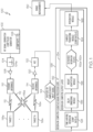
- FIG. 1 is a block schematic diagram of an example of a radar system 100 in accordance with an embodiment of the present disclosure.
- the radar system 100 is a below-noise after transmit (BAT) chirp radar.
- the radar system 100 includes a radio frequency (RF) signal generator 102 for generating an RF signal or radar signal.
- the RF signal generator 102 is a chirp pulse generator that is adjustable to generate a chirp pulse 104 at a predetermined chirp rate 106 or chirp rate that is selectable by a user.
- the RF signal comprises a chirped or step chirped waveform 104a.
- An amplifier 108 amplifies the chirp pulse 104.
- the radar system 100 also includes a transmit antenna 110 or antennas for transmitting the RF signal 112 or radar signal amplified by the amplifier 108.
- the radar system 100 additionally includes a receive antenna 114 or antennas for receiving a plurality of reflected signals 116a-116n created by a plurality of targets 118a-118n reflecting the RF signal 112 or radar signal.
- the reflected signals 116a-116n include background noise.
- a receive amplifier 120 amplifies the received reflected signals 116a-116n and adds receiver noise.
- An analog-to-digital converter (ADC) 122 digitizes or samples the plurality of reflected signals 116a-116n to provide a digitized or sampled noisy input signal 124.
- a reservoir computer 126 receives the noisy input signal 124 from the ADC 122.
- the reservoir computer 126 includes a time-varying reservoir 128.
- the reservoir computer 126 is configured to de-noise the noisy input signal 124 and to provide a range measurement 130 for each of the plurality of targets 118a-118n as described in more detail herein.
- An example of the reservoir computer 126 and components of the reservoir computer 126 will be described in more detail with reference to FIGS. 2-4 .
- the reservoir computer 126 includes a cognitive radar processor 132 or may also be referred to as a cognitive radar processor 132.
- the reservoir computer 126 or cognitive radar processor 132 includes the time-varying reservoir 128.
- the reservoir computer 126 or cognitive radar processor 132 also includes a reservoir computer output layer 134.
- the reservoir computer 126 or cognitive radar processor 132 additionally includes a delay embedding module 136 and a weight adaptation module 138.
- the delay embedding module 136 and the weight adaptation module 138 are components of the reservoir computer output layer 134.
- FIG. 2 is a block schematic diagram of an example of the time-varying reservoir 128, delay embedding module 136 and weight adaptation module 138 in accordance with an embodiment of the present disclosure.
- the reservoir computer 126 including the time-varying reservoir 128, delay embedding module 136 and weight adaptation module 138 analyze the noisy input signal 124 using predictive filtering at block 904 in FIG. 9 to separate a predictive signal pattern and unpredictable noise pattern at block 906 in FIG. 9 .
- the time-varying reservoir 128 includes a multiplicity of time-varying reservoir states 140a-140n.
- the time-varying reservoir 128 is configured to linearly map the noisy input signal 124 into respective reservoir states 140a-140n to create a high-dimensional state-space representation 142 or multi-dimensional state-space representation of the noisy input signal 124.
- the time-varying reservoir 128 includes a state transition matrix 144 that includes a predetermined block diagonal structure 146 that is optimized for signal de-noising and efficient implementation in hardware as described in more detail herein.
- the time-varying reservoir 128 includes a recurrent neural network 402 ( FIG. 4 ) including a plurality of reservoir nodes 404. Each reservoir node 404 corresponding to one of the time-varying reservoir states 140a-140n.
- the delay embedding module 136 is configured to receive a reservoir state signal 148a-148n corresponding to each respective time-varying reservoir state 140a-140n and to generate a delay embedded reservoir state signal 150a-150n corresponding to each time-varying reservoir state 140a-140n that represents a history 151 of the time-varying reservoir states 140a-140n or reservoir state dynamics over a short-time period based on a predetermined time delay 154 of the delay embedding module 136.
- the short-time period or predetermined time period is based on the frequency of the received signal, which would be a predetermined time based on the operating frequency of the radar.
- the delay embedding module 136 includes a delay embedded reservoir state vector 157 that has a different state transition matrix 159 compared to the state transition matrix 144 of the time-varying reservoir 128 to enable time-varying dynamics.
- the weight adaptation module 138 receives the delay embedded reservoir state signals 150a-150n from the delay embedding module 136.
- the weight adaptation module 138 is configured to produce a de-noised reservoir state signal 152a-152n for each time-varying reservoir state 140a-140n or reservoir state signal 148a-148n.
- the de-noised reservoir state signals 152a-152n corresponds to the noisy input signal 124 being de-noised to provide a de-noised input signal 158.
- the weight adaptation module 138 is configured to produce a prediction 156 of the noisy input signal 124 (input signal including noise) at a predetermined future time from the delay embedded reservoir state signals 150a-150n and to use the prediction 156 of the noisy input signal 124 to separate the noise from (de-noise) the noisy input reservoir state signals 148a-148n using a gradient descent learning algorithm 160. Weights 162a-162n of the weight adaptation module 138 are determined using the gradient descent learning algorithm 160. Accordingly, the weight adaptation module 138 is configured to use predictive filtering to separate a predictive signal pattern from an unpredictable noise pattern (blocks 904 and 906 in FIG. 9 ).
- the gradient descent learning algorithm 160 predicts next samples of a predictable part of the noisy input signal 124 and determines a difference between samples as the unpredictable noise pattern.
- An inverse noise signal corresponding to the unpredictable noise pattern is applied to the prediction 156 of the noisy input signal 124 to cancel the unpredictable noise pattern (block 908 in FIG. 9 ) and provide the de-noised input signal 158 or enhanced RF signal or return radar signal (block 910 in FIG. 9 ) without the noise cancelled.
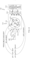
- the reservoir computer 126 or cognitive radar processor 132 further includes a chirplet transform module 164 and an integration module 166.
- FIG. 3 is a block schematic diagram of an example of the chirplet transform module 164 and integration module 166 in accordance with an embodiment of the present disclosure.
- the chirplet transform module 164 receives the de-noised reservoir states or de-noised reservoir state signals 152a-152n, corresponding to the de-noised input signal 158, from the weight adaptation module 138.
- the chirplet transform module 164 generates a real-time de-noised time-varying spectrogram 168 of the de-noised input signal 158 representing the reflected signals 116a-116n from the plurality of targets 118a-118n.
- the real-time de-noised time-varying spectrogram 168 may also be represented as a chirplet spectrogram via a mathematical transformation.
- the chirplet transform module 164 is configured to map each of the de-noised reservoir states 170a-170n or de-noised reservoir state signals 152a-152n to the range measurement 130 of each of the plurality of targets 118a-118n.
- the de-noised reservoir states 170a-170n define a bank of time-varying filters 172 at a chirp rate 106 set by the transmit chirp pulse 104 of the transmitted RF signal 112 or the radar signal.
- a response of the time-varying filters 172 to chirps received at different times are equivalent to a response of a bank of 1-pole infinite impulse response (IIR) filters to different frequencies.
- IIR infinite impulse response
- the integration module 166 is configured for integrating the real-time de-noised time-varying spectrogram 168 of the de-noised input signal 158 to create an integrated de-noised spectrogram 174 and for mapping the integrated de-noised spectrogram 174 to the range measurements 130a-130n.
- the integration module 166 is configured to increase a signal-to-noise ratio of each de-noised reservoir state signal 152a-152n by pulse compression including integrating or summing an output 178a-178n of each de-noised reservoir state 170a-170n or de-noised reservoir state signal 152a-152n.
- the integration module 166 includes a plurality of summing nodes 176a-176n for integrating each of the de-noised input signals 158 represented in the real-time de-noised time-varying spectrogram 168.
- FIG. 4 is a diagram of an example of the time-varying reservoir computer 126 in accordance with an embodiment of the present disclosure.
- the reservoir computer 126 includes a cognitive signal de-noising architecture 400 that is based on a form of neuromorphic (brain-inspired) signal processing known as reservoir computing.
- Reservoir computing is a special form of a recurrent neural network 402 (a neural network with feedback connections) that operates by projecting the input signal vector or input signal 124 into a high-dimensional reservoir state space representation 142 ( FIG. 2 ) which contains an equivalent dynamical model of the signal generation process capturing all of the available and actionable information about the input signal 124.
- the reservoir computer 126 has readout layers 406 that can be trained, either off-line or on-line, to learn desired outputs by utilizing state functions. Accordingly, the reservoir computer 126 has the power of a recurrent neural network 402 to model non-stationary (time-varying) processes and phenomena, but with simple readout layers 406 and training algorithms that are both accurate and efficient.
- the reservoir computer 126 is configured to implement an adaptable state-space filter or time-varying filters 172 ( FIG. 3 ).
- A is the reservoir connectivity matrix that determines the filter pole locations
- B is the vector mapping the input to the reservoir
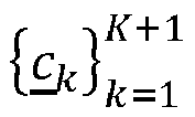
- C ( t ) is the set of tunable output layer weights 162a-162n that map the reservoir states 140a-140n to the output or de-noised reservoir state signals 152a-152n and determine the filter zero locations
- D ( t ) is the (rarely used) direct mapping from input to output.
- FIG. 4 illustrates the direct correspondence between parameters of the state-space representation 142 and components in the reservoir computer 126.
- the reservoir computer 126 implements an adaptable state-space filter where the poles are fixed, but the zeros are adapted in real-time based on the input signal 124.
- the reservoir computer 126 maps an input signal vector or input signal 124 to the high-dimensional state-space representation 142 that models the underlying time-varying dynamics of the signal generation process.
- the reservoir states 140a-140n can be mapped to useful outputs 408, including de-noised inputs, signal classes, separated signals, and anomalies using the trainable linear readout layers 406. There is a direct correspondence between state-space representation components and parameters in the reservoir computer 126.
- the weights in both the reservoir connectivity matrix ( A ) and the input-to-reservoir mapping vector ( B ) are typically chosen randomly (e.g., entries of A and B can be independent, identically distributed samples from a zero-mean, unit variance Gaussian distribution).
- the reservoir state update require computation proportional to the square of the number of reservoir nodes 404, which become infeasible for low-power hardware instantiations as the number of reservoir nodes 404 increases.
- ⁇ T A T -1
- B ⁇ T B
- ⁇ ( t ) T -1 T C ( t )
- D ⁇ ( t ) D ( t ).
- This dynamical system has the exact same input/output behavior as the original system, but with the appropriate choice of T , the reservoir transition matrix ⁇ can be designed to have diagonal or block diagonal structure. This will enable the computation of the reservoir state update to scale linearly with the number of reservoir nodes 404, thus enabling efficient implementation in low-power hardware.
- the reservoir state transition matrix A is constructed such that it is in a 2 ⁇ 2 block diagonal form.
- Each 2 ⁇ 2 block in the state matrix A corresponds to a single pole Infinite Impulse Response (IIR) filter.
- IIR Infinite Impulse Response
- the placement of the pole for each 2 ⁇ 2 block can be selected so that the reservoir state matrix in aggregate models a bank of IIR filters or bank of time-varying filters 172.
- the matrix A must have eigenvalues that are purely real and negative corresponding to purely damped modes or eigenvalues that come in complex conjugate pairs, with negative real parts to the eigenvalues.
- Phase delay embedding used in delay embedding module 136 is a technique developed in dynamical system theory to model the dynamics of a chaotic system from its observation u 0 ( t ) using delayed versions of the observation as a new input vector u ( t ).
- an unknown (potentially chaotic) dynamical system is assumed embedded in an N -dimensional state space having an m-dimensional attractor. This means that though the state space has N parameters, signals from the dynamical system form trajectories that all lie on an m-dimensional sub-manifold M of the state space, and can theoretically (though not practically) be specified by as few as m parameters.
- the observations (received signal) u 0 ( t ) h [ x ⁇ ( t )] is a projection of the state space.
- the phase delay embedding produces a new input vector u ( t ) from n delayed versions of the observation signal u 0 ( t ) concatenated together.
- phase delay embedding u ( t ) preserves the topological structure (i.e., shape) of the dynamical system, and thus can be used to reconstruct the dynamical system from observations.
- FIG. 5 is a schematic diagram of an example of a dynamic reservoir 500 in accordance with an embodiment of the present disclosure.
- the delay-embedding is applied to each of the reservoir states 140a-140n ( FIG. 2 ) to obtain the short-time history of the reservoir state dynamics or history 151 of the time-varying reservoir states 140a-140b.
- a short-term prediction method is used for signal de-noising. Given that delay-embedded observations can effectively model dynamical system behavior, the history 151 of these reservoir states 140a-140n are leveraged or used to perform short-term predictions of the observations.
- the cognitive radar processor 132 includes a wideband (up to 30 GHz) frontend that provides input to the dynamic reservoir 500.
- the wideband frontend refers to antennas, amplifiers, ADCs, etc. before the reservoir computer 126 that are configured to handle or support a desired wide bandwidth.
- the weights 162a-162n of the output layer 134 are adapted via the gradient descent learning algorithm 160 described below.
- the gradient descent learning algorithm 160 is based on short-time prediction of the input signal 124, seeking to represent the output as a linear combination of the historical reservoir states. Because noise is random and unpredictable, the predicted signal y ( t ) ⁇ ⁇ o ( t + ⁇ ) will be free of noise.
- the gradient descent learning algorithm 160 is used to enforce exact prediction of the current time point that is used in the delay embedding module 136.
- the predicted input value at time ( t + ⁇ ) is calculated from the current value of the output weights ( c k ( t ), d ( t )) 162a-162n and the current and past values of the states ( x ) and the input ( u ).
- the ODEs for the dynamic reservoir 500 and the weight adaptation module 138 can be implemented directly in analog hardware.
- To implement the above ODEs in software or efficient digital hardware e.g., field-programmable gate arrays (FPGAs) or custom digital application-specific integrated circuits (ASICs)
- the update equations must be discretized.
- the ODEs are converted to delay difference equations (DDEs).
- DDEs delay difference equations
- FIG. 6A is an example of approximation of an input signal u(t) 600 using uniform sampling with sampling period ⁇ t in accordance with an embodiment of the present disclosure.
- FIG. 6B is an example of using a linear basis function for approximation of the input signal u(t) 600 in accordance with another embodiment of the present disclosure.
- input signal u(t) 600 corresponds to input signal 124.
- u i def u t ⁇ i ⁇ 1 ⁇ t , 1 ⁇ i ⁇ n e + 1 , are collected.
- n e ⁇ ⁇ t is the number of sampling intervals within the time window defined by ⁇ (see
- N i ( t ) T ( t - ( i - t ) ⁇ t ) is a shifted version of the triangle function, T ( t ):
- T t ⁇ 1 ⁇ t / ⁇ t 0 ⁇ t ⁇ ⁇ t 1 + t / ⁇ t ⁇ ⁇ t ⁇ t ⁇ 0 0 otherwise
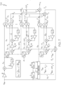
- FIG. 7 is a schematic diagram of an example a cognitive radar processor 700 in accordance with an embodiment of the present disclosure.
- the cognitive radar processor 700 shown in FIG. 7 is amenable to implementation on an FPGA or custom digital ASIC.
- Algorithm 1 is a cognitive signal de-noising iterative algorithm and includes the following operations:
- a linear reservoir with N nodes combined with the phase delay embedding of size K is a linear reservoir with ( K + 1) N nodes where the state transition matrix ⁇ and input-to-reservoir map B ⁇ have the above structured forms.
- the identity matrices are a computationally efficient mechanism for applying a static reservoir state transition matrix ⁇ to the history 151 of the reservoir states 140a-140b.
- the sub-reservoir specified by A 0 will have resonances at frequencies, f 1 ... f p .
- Matrices A 1 ... A K then have rows that are cyclically shifted versions of the rows of A 0 .
- the sub-reservoirs specified by A 1 ... A K all have the same resonant frequencies as A 0 , but are applied to different elements of the state vector.
- u ( t ) sin ⁇ 0 + 2 ⁇ f 1 + f p ⁇ f 1 T t with sweep rate, T
- the same state of the time-varying reservoir 128 will detect and track this signal as it sweeps from frequency f 1 to frequency f p .
- Note that for the chirp-optimized reservoir because each A i is a permuted version of A 0 , the computation of the reservoir state update is not significantly increased compared to the static reservoir.
- the real-time de-noised time-varying spectrogram 168 is provided using the de-noised reservoir states 170a-170n as previously described. Because the de-noised reservoir states 170a-170n are for a time-varying reservoir 128, they can be interpreted as the response to a bank of time-varying filters 172. Thus, for the chirp-optimized reservoir described above, the set of de-noised reservoir states 170a-170n form a chirplet spectrogram or real-time de-noised time-varying spectrogram 168.
- This chirplet spectrogram or real-time de-noised time-varying spectrogram 168 can be used for a variety of real-time signal analysis tasks, such as detection, separation of signals, and tracking of individual radar pulses within an input wideband signal mixture.
- the de-noised reservoir states 170a-170n are interpreted as a bank of time-varying filters 172 at the chirp rate 106 set by the transmit chirp pulse 104.
- the response of the time-varying filters 172 to chirps received at different times are equivalent to the response of a bank of narrowband 1-pole IIR filters to different frequencies. This is precisely the function of the de-chirp functional block in traditional radar receivers. Therefore the different responses of the de-noised reservoir states 170a-170n represent different range measurements 130a-130n to targets 118a-118n reflecting the transmitted chirp pulses 104.
- the de-noised reservoir states 170a-170n represent relative range measurements r i inside the radar return receive window or time duration the receiver in on and able to receiving signals.
- the signal's signal-to-noise ratio can be further increased through (effective) "pulse compression” by integrating (summing) the output of a single reservoir state (a single filter in the bank of time-varying filters 172) using integration module 166 as previously described. Note that this demonstrates that the SNR increase due to the reservoir computer de-noising is in addition to the effective gain increase obtained by pulse compression in traditional radar applications.
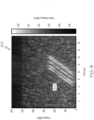
- FIG. 8 is an example of a chirplet spectrogram 800 of a de-noised input signal in accordance with an embodiment of the present disclosure.
- FIG. 8 shows the chirplet transform read off from the de-noised reservoir states 170a-170n.
- the horizontal lines in a chirplet spectrogram or diagonal lines in a standard spectrogram 802 correspond to (simulated) received radar returns at the transmit chirp rate 106 of 31.831*10 -6 fs 2 where fs is the sample rate of the ADC.
- the y-axis represents the relative range measurements r i inside the radar return receive window.
- the absolute range measurement can be computed from the delay between the transmit time T Tx and the receive time T Rx using the equations for R 0 and R i above.
- the signal's SNR can be further increased through (effective) pulse compression (integration along the x-axis). Note that this demonstrates that the SNR increase due to the reservoir computer de-noising is in addition to the effective gain increase obtained by pulse compression.
- FIG. 9 is a flow chart of an example of a method 900 for measuring a range to each of a plurality of targets using a below-noise after transmit (BAT) Chirp Radar in accordance with an embodiment of the present disclosure.
- the method 900 is embodied in and performed by the reservoir computer 126 or cognitive radar processor 132 in FIG. 1 . Accordingly, the reservoir computer 126 or cognitive radar processor 132 is configured to perform a set functions defined by the method 900.
- a noisy input signal is received by a cognitive radar processor.
- the noisy input signal includes a plurality of reflected RF signals or radar signals from a plurality of targets and noise.
- predictive filtering including a time-varying reservoir is used to analyze the noisy input signal.
- the noisy input signal is analyzed to separate a predictive signal pattern and an unpredictable noise pattern for identifying the unpredictable noise pattern.
- an inverse noise signal is applied to the noisy input signal to cancel the unpredictable noise pattern.
- the inverse noise signal corresponds to the unpredictable noise pattern.
- an enhanced RF signal or return radar signal is generated in response to cancelling the unpredictable noise pattern from the predictive signal pattern.
- the enhanced RF signal or return radar signal is mapped to range measurements for each of the targets.
- FIG. 10 is a flow chart of an example of a method 1000 for measuring a range to each of a plurality of targets using a below-noise after transmit (BAT) Chirp Radar in accordance with another embodiment of the present disclosure.
- the method 1000 is embodied in and performed by the reservoir computer 126 or cognitive radar processor 132 in FIG. 1 . Accordingly, the reservoir computer 126 or cognitive radar processor 132 is configured to perform a set functions defined by the method 1000.
- a noisy input signal is received.
- the noisy input signal 124 is a time-series of data points from a plurality of reflected signals 116a-116n sampled from a bandwidth greater than about 30 GHz. Although other bandwidths may also be sampled.
- the noisy input signal is linearly mapped into a time-varying reservoir.
- the time-varying reservoir includes a multiplicity of time-varying reservoir states.
- a high-dimensional state-space representation or multi-dimensional state-space representation of the reflected signals is created by combining the noisy input signal with the time-varying reservoir states of the time-varying reservoir.
- a delay embedded reservoir state signal is generated from each time-varying reservoir state that provides a finite temporal record of the reservoir state dynamics or history of the time-varying reservoir states.
- each time-varying reservoir state is de-noised which corresponds to de-noising the noisy input signal so that noise is removed and signals corresponding to the reflected signals without noise remain.
- a real-time de-noised time-varying spectrogram of the noisy input signal is generated from the de-noised reservoir states or de-noised reservoir state signals.
- the de-noised time-varying spectrogram is integrated in an output layer of the cognitive radar processor.
- the integrated de-noised time-varying spectrogram is mapped to the range measurement for each of the plurality of targets.
Landscapes
- Engineering & Computer Science (AREA)
- Remote Sensing (AREA)
- Radar, Positioning & Navigation (AREA)
- Physics & Mathematics (AREA)
- General Physics & Mathematics (AREA)
- Computer Networks & Wireless Communication (AREA)
- Theoretical Computer Science (AREA)
- Data Mining & Analysis (AREA)
- Artificial Intelligence (AREA)
- Evolutionary Computation (AREA)
- Life Sciences & Earth Sciences (AREA)
- General Engineering & Computer Science (AREA)
- Molecular Biology (AREA)
- Computing Systems (AREA)
- Biomedical Technology (AREA)
- Biophysics (AREA)
- Computational Linguistics (AREA)
- General Health & Medical Sciences (AREA)
- Software Systems (AREA)
- Health & Medical Sciences (AREA)
- Mathematical Physics (AREA)
- Computer Vision & Pattern Recognition (AREA)
- Evolutionary Biology (AREA)
- Bioinformatics & Computational Biology (AREA)
- Bioinformatics & Cheminformatics (AREA)
- Electromagnetism (AREA)
- Radar Systems Or Details Thereof (AREA)
Description
- The present disclosure relates to radars and radar systems and more particularly to a below-noise after transmit (BAT) Chirp Radar.
- Detecting below-noise radio frequency (RF) signals, such as radar signals involves de-noising the RF signals or radar signals to obtain a useable signal or radar return that can be processed to extract the desired information. State-of-the-art systems for measuring the range to targets or terrain over an ultra-wide bandwidth (greater than about 30 Giga Hertz (GHz), enabling high resolution) at long range require high rate analog-to-digital converters (ADCs) and some combination of a high power transmitter or a large antenna aperture. Such high-rate ADCs are expensive and consume a substantial amount of power, and due to fundamental physical limits, are not capable of achieving a sampling rate needed to capture an ultra-wide bandwidth as defined above. To mitigate this, current wideband radar systems use chirp or step-chirp waveforms that are de-chirped upon receipt, increasing the required length of the transmit pulse and constraining the operational range for target detection to a particular range window. Additionally, the detection algorithms of current radar systems are typically based on the fast Fourier transform, with high computational complexity and memory requirements that make it difficult to operate such systems in real-time over an ultra-wide bandwidth. The high power transmitters needed to detect targets at long range with sufficient signal-to-noise ratio (SNR) require a substantial amount of instantaneous power. This can be mitigated with a larger antenna; however, increasing aperture size to reduce transmit power increases weight which makes the approach infeasible for applications were there are significantly low size, weight and power requirements.
- Conventional methods for de-noising fall into two categories: filter-based methods, and training-based approaches. Filter-based methods use filtering to smooth out noise from a signal, but are too simplistic to simultaneously maintain the low-frequency long-term trends of a signal while adapting to the high-frequency abrupt transitions. Training-based methods rely on a "dictionary" that models the signals of interest. Such a dictionary must be trained in an offline process, and requires training data that may not be available. In addition, the dictionary often requires a large amount of memory and computation to be stored and leveraged on a platform rendering such methods impractical for applications where small size, weight and fast performance are important characteristics.
-
U.S. patent No. 9,749,007 -
U.S. patent No. 5,402,520 , which is considered closest prior art, discusses a neural network method and apparatus for retrieving signals embedded in noise and analysing the retrieved signals, but is silent in particular about the feature of the claimed invention that the de-noised reservoir states define a bank of time-varying filters at a chirp rate, set by a transmit chirp of a RF or radar signal, with the response of the time-varying filters to chirps received at different times being equivalent to a response of a bank of 1-pole infinite impulse response (IIR) filters to different frequencies. - According to one aspect, a radar system is provided as set forth in the appended claims.
- According to another aspect, a cognitive radar processor is provided as set forth in the appended claims.
- The features, functions, and advantages that have been discussed can be achieved independently in various embodiments or may be combined in yet other embodiments further details of which can be seen with reference to the following description and drawings.
-
-
FIG. 1 is a block schematic diagram of an example of a radar system in accordance with an embodiment of the present disclosure. -
FIG. 2 is a block schematic diagram of an example of a time-varying reservoir, delay embedding module and weight adaptation module in accordance with an embodiment of the present disclosure. -
FIG. 3 is a block schematic diagram of an example of a chirplet transform module and integration module on accordance with an embodiment of the present disclosure. -
FIG. 4 is a diagram of an example of time-varying reservoir computer in accordance with an embodiment of the present disclosure. -
FIG. 5 is a schematic diagram of an example of a dynamic reservoir in accordance with an embodiment of the present disclosure. -
FIG. 6A is an example of approximation of an input signal u(t) using uniform sampling with with sampling period Δt in accordance with an embodiment of the present disclosure. -
FIG. 6B is an example of using a linear basis function for approximation of the input signal u(t) in accordance with an embodiment of the present disclosure. -
FIG. 7 is a schematic diagram of an example a cognitive radar processor in accordance with an embodiment of the present disclosure. -
FIG. 8 is an example of a spectrogram of a de-noised signal in accordance with an embodiment of the present disclosure. -
FIG. 9 is a flow chart of an example of a method for measuring a range to each of a plurality of targets using a below-noise after transmit (BAT) Chirp Radar. -
FIG. 10 is a flow chart of an example of a method for measuring a range to each of a plurality of targets using a BAT Chirp Radar. - The following detailed description of embodiments refers to the accompanying drawings, which illustrate specific embodiments of the disclosure. Other embodiments having different structures and operations do not depart from the scope of the present disclosure. Like reference numerals may refer to the same element or component in the different drawings.
- The embodiments described herein are applicable to radar receivers or radar systems that can perform real-time processing of signals over an ultra-wide bandwidth. The exemplary embodiments provide expanded situational awareness, providing the core functionality required for ultra-low latency signal detection and analysis over about a 30 GHz instantaneous bandwidth to enable real-time resource allocation based on the RF environment. This performance can be achieved on computing platforms with orders of magnitude lower size, weight, and power. The time-varying reservoir computer described enables rapid de-noising and detection of non-stationary signals such as chirps that are widely used in radar systems on a wide variety of platforms.
- In addition to aerospace applications, such as onboard aircraft or in space rendezvous operations, the cognitive radar processor described herein has other application enabling multi-static radar and cognitive radio in low signal-to-noise ratio (SNR) conditions. The time-varying reservoir computer is particularly useful to detect and track frequency-modulated continuous wave (FMCW) signals or chirp pulses that are used in a wide variety of automotive radar systems.
- Additional capabilities of the CRP or reservoir computer include generating a real-time time-varying spectrogram that further facilitates situational awareness for piloted airborne platforms or vehicles, unmanned aerial vehicles (UAV), or automated or piloted space platforms.
-
FIG. 1 is a block schematic diagram of an example of aradar system 100 in accordance with an embodiment of the present disclosure. In accordance with an example described herein, theradar system 100 is a below-noise after transmit (BAT) chirp radar. Theradar system 100 includes a radio frequency (RF)signal generator 102 for generating an RF signal or radar signal. In accordance with an embodiment, theRF signal generator 102 is a chirp pulse generator that is adjustable to generate achirp pulse 104 at apredetermined chirp rate 106 or chirp rate that is selectable by a user. Accordingly, in accordance with an embodiment, the RF signal comprises a chirped or stepchirped waveform 104a. Anamplifier 108 amplifies thechirp pulse 104. - The
radar system 100 also includes atransmit antenna 110 or antennas for transmitting theRF signal 112 or radar signal amplified by theamplifier 108. Theradar system 100 additionally includes areceive antenna 114 or antennas for receiving a plurality ofreflected signals 116a-116n created by a plurality oftargets 118a-118n reflecting theRF signal 112 or radar signal. Thereflected signals 116a-116n include background noise. Areceive amplifier 120 amplifies the receivedreflected signals 116a-116n and adds receiver noise. - An analog-to-digital converter (ADC) 122 digitizes or samples the plurality of
reflected signals 116a-116n to provide a digitized or samplednoisy input signal 124. Areservoir computer 126 receives thenoisy input signal 124 from the ADC 122. Thereservoir computer 126 includes a time-varying reservoir 128. Thereservoir computer 126 is configured to de-noise thenoisy input signal 124 and to provide arange measurement 130 for each of the plurality oftargets 118a-118n as described in more detail herein. An example of thereservoir computer 126 and components of thereservoir computer 126 will be described in more detail with reference toFIGS. 2-4 . Thereservoir computer 126 includes acognitive radar processor 132 or may also be referred to as acognitive radar processor 132. - The
reservoir computer 126 orcognitive radar processor 132 includes the time-varying reservoir 128. Thereservoir computer 126 orcognitive radar processor 132 also includes a reservoircomputer output layer 134. Thereservoir computer 126 orcognitive radar processor 132 additionally includes adelay embedding module 136 and aweight adaptation module 138. In accordance with an embodiment, thedelay embedding module 136 and theweight adaptation module 138 are components of the reservoircomputer output layer 134. - Referring also to
FIG. 2, FIG. 2 is a block schematic diagram of an example of the time-varyingreservoir 128,delay embedding module 136 andweight adaptation module 138 in accordance with an embodiment of the present disclosure. As described in more detail herein, thereservoir computer 126 including the time-varyingreservoir 128,delay embedding module 136 andweight adaptation module 138 analyze thenoisy input signal 124 using predictive filtering atblock 904 inFIG. 9 to separate a predictive signal pattern and unpredictable noise pattern atblock 906 inFIG. 9 . The time-varyingreservoir 128 includes a multiplicity of time-varyingreservoir states 140a-140n. The time-varyingreservoir 128 is configured to linearly map thenoisy input signal 124 intorespective reservoir states 140a-140n to create a high-dimensional state-space representation 142 or multi-dimensional state-space representation of thenoisy input signal 124. As described in more detail herein, the time-varyingreservoir 128 includes astate transition matrix 144 that includes a predetermined blockdiagonal structure 146 that is optimized for signal de-noising and efficient implementation in hardware as described in more detail herein. - In accordance with an embodiment, the time-varying
reservoir 128 includes a recurrent neural network 402 (FIG. 4 ) including a plurality ofreservoir nodes 404. Eachreservoir node 404 corresponding to one of the time-varyingreservoir states 140a-140n. - The
delay embedding module 136 is configured to receive areservoir state signal 148a-148n corresponding to each respective time-varyingreservoir state 140a-140n and to generate a delay embeddedreservoir state signal 150a-150n corresponding to each time-varyingreservoir state 140a-140n that represents ahistory 151 of the time-varyingreservoir states 140a-140n or reservoir state dynamics over a short-time period based on apredetermined time delay 154 of thedelay embedding module 136. The short-time period or predetermined time period is based on the frequency of the received signal, which would be a predetermined time based on the operating frequency of the radar. Thedelay embedding module 136 includes a delay embeddedreservoir state vector 157 that has a differentstate transition matrix 159 compared to thestate transition matrix 144 of the time-varyingreservoir 128 to enable time-varying dynamics. - The
weight adaptation module 138 receives the delay embeddedreservoir state signals 150a-150n from thedelay embedding module 136. Theweight adaptation module 138 is configured to produce a de-noisedreservoir state signal 152a-152n for each time-varyingreservoir state 140a-140n orreservoir state signal 148a-148n. The de-noisedreservoir state signals 152a-152n corresponds to thenoisy input signal 124 being de-noised to provide ade-noised input signal 158. Theweight adaptation module 138 is configured to produce aprediction 156 of the noisy input signal 124 (input signal including noise) at a predetermined future time from the delay embeddedreservoir state signals 150a-150n and to use theprediction 156 of thenoisy input signal 124 to separate the noise from (de-noise) the noisy inputreservoir state signals 148a-148n using a gradientdescent learning algorithm 160.Weights 162a-162n of theweight adaptation module 138 are determined using the gradientdescent learning algorithm 160. Accordingly, theweight adaptation module 138 is configured to use predictive filtering to separate a predictive signal pattern from an unpredictable noise pattern (blocks 904 and 906 inFIG. 9 ). The gradientdescent learning algorithm 160 predicts next samples of a predictable part of thenoisy input signal 124 and determines a difference between samples as the unpredictable noise pattern. An inverse noise signal corresponding to the unpredictable noise pattern is applied to theprediction 156 of thenoisy input signal 124 to cancel the unpredictable noise pattern (block 908 inFIG. 9 ) and provide thede-noised input signal 158 or enhanced RF signal or return radar signal (block 910 inFIG. 9 ) without the noise cancelled. - Referring to
FIG. 1 andFIG. 3 , thereservoir computer 126 orcognitive radar processor 132 further includes achirplet transform module 164 and anintegration module 166.FIG. 3 is a block schematic diagram of an example of thechirplet transform module 164 andintegration module 166 in accordance with an embodiment of the present disclosure. Thechirplet transform module 164 receives the de-noised reservoir states or de-noisedreservoir state signals 152a-152n, corresponding to thede-noised input signal 158, from theweight adaptation module 138. Thechirplet transform module 164 generates a real-time de-noised time-varyingspectrogram 168 of thede-noised input signal 158 representing the reflectedsignals 116a-116n from the plurality oftargets 118a-118n. The real-time de-noised time-varyingspectrogram 168 may also be represented as a chirplet spectrogram via a mathematical transformation. Thechirplet transform module 164 is configured to map each of thede-noised reservoir states 170a-170n or de-noisedreservoir state signals 152a-152n to therange measurement 130 of each of the plurality oftargets 118a-118n. Thede-noised reservoir states 170a-170n define a bank of time-varyingfilters 172 at achirp rate 106 set by the transmitchirp pulse 104 of the transmitted RF signal 112 or the radar signal. A response of the time-varyingfilters 172 to chirps received at different times are equivalent to a response of a bank of 1-pole infinite impulse response (IIR) filters to different frequencies. - The
integration module 166 is configured for integrating the real-time de-noised time-varyingspectrogram 168 of thede-noised input signal 158 to create an integratedde-noised spectrogram 174 and for mapping the integratedde-noised spectrogram 174 to therange measurements 130a-130n. Theintegration module 166 is configured to increase a signal-to-noise ratio of each de-noisedreservoir state signal 152a-152n by pulse compression including integrating or summing anoutput 178a-178n of eachde-noised reservoir state 170a-170n or de-noisedreservoir state signal 152a-152n. In accordance with an embodiment, theintegration module 166 includes a plurality of summingnodes 176a-176n for integrating each of the de-noised input signals 158 represented in the real-time de-noised time-varyingspectrogram 168. - Referring also to
FIG. 4, FIG. 4 is a diagram of an example of the time-varyingreservoir computer 126 in accordance with an embodiment of the present disclosure. Thereservoir computer 126 includes a cognitivesignal de-noising architecture 400 that is based on a form of neuromorphic (brain-inspired) signal processing known as reservoir computing. Reservoir computing is a special form of a recurrent neural network 402 (a neural network with feedback connections) that operates by projecting the input signal vector orinput signal 124 into a high-dimensional reservoir state space representation 142 (FIG. 2 ) which contains an equivalent dynamical model of the signal generation process capturing all of the available and actionable information about theinput signal 124. Thereservoir computer 126 has readoutlayers 406 that can be trained, either off-line or on-line, to learn desired outputs by utilizing state functions. Accordingly, thereservoir computer 126 has the power of a recurrentneural network 402 to model non-stationary (time-varying) processes and phenomena, but withsimple readout layers 406 and training algorithms that are both accurate and efficient. - The
reservoir computer 126 is configured to implement an adaptable state-space filter or time-varying filters 172 (FIG. 3 ). A linear reservoir computer has the following state-space representation:

output layer weights 162a-162n that map thereservoir states 140a-140n to the output or de-noisedreservoir state signals 152a-152n and determine the filter zero locations, and D(t) is the (rarely used) direct mapping from input to output. Similarly, the output layer weights ( C ) determine the filter zero locations.FIG. 4 illustrates the direct correspondence between parameters of the state-space representation 142 and components in thereservoir computer 126. As the tunableoutput layer weights 162a-162n are adaptable, thereservoir computer 126 implements an adaptable state-space filter where the poles are fixed, but the zeros are adapted in real-time based on theinput signal 124. Thereservoir computer 126 maps an input signal vector orinput signal 124 to the high-dimensional state-space representation 142 that models the underlying time-varying dynamics of the signal generation process. The reservoir states 140a-140n can be mapped touseful outputs 408, including de-noised inputs, signal classes, separated signals, and anomalies using the trainable linear readout layers 406. There is a direct correspondence between state-space representation components and parameters in thereservoir computer 126. - In conventional reservoir computers, the weights in both the reservoir connectivity matrix ( A ) and the input-to-reservoir mapping vector ( B ) are typically chosen randomly (e.g., entries of A and B can be independent, identically distributed samples from a zero-mean, unit variance Gaussian distribution). The reservoir state update require computation proportional to the square of the number of
reservoir nodes 404, which become infeasible for low-power hardware instantiations as the number ofreservoir nodes 404 increases. - Because the
reservoir computer 126 is a linear dynamical system, a linear transformation T can be applied to obtain a new state vector x́ (t) = Tx (t), to provide an equivalent dynamical system:

T C (t), and D́(t) = D(t). This dynamical system has the exact same input/output behavior as the original system, but with the appropriate choice of T , the reservoir transition matrix  can be designed to have diagonal or block diagonal structure. This will enable the computation of the reservoir state update to scale linearly with the number ofreservoir nodes 404, thus enabling efficient implementation in low-power hardware. - In accordance with an embodiment, the reservoir state transition matrix A is constructed such that it is in a 2 × 2 block diagonal form. Each 2 × 2 block in the state matrix A corresponds to a single pole Infinite Impulse Response (IIR) filter. Using standard IIR filter design techniques, the placement of the pole for each 2 × 2 block can be selected so that the reservoir state matrix in aggregate models a bank of IIR filters or bank of time-varying
filters 172. For example, for a real passive IIR filter, the matrix A must have eigenvalues that are purely real and negative corresponding to purely damped modes or eigenvalues that come in complex conjugate pairs, with negative real parts to the eigenvalues. Thus, the block-diagonal matrix A will have the form:
- Here p is the number of complex conjugate poles, with N = 2p,


- Phase delay embedding used in
delay embedding module 136 is a technique developed in dynamical system theory to model the dynamics of a chaotic system from its observation u 0(t) using delayed versions of the observation as a new input vector u (t). To use phase delay embedding theory, an unknown (potentially chaotic) dynamical system is assumed embedded in an N-dimensional state space having an m-dimensional attractor. This means that though the state space has N parameters, signals from the dynamical system form trajectories that all lie on an m-dimensional sub-manifold M of the state space, and can theoretically (though not practically) be specified by as few as m parameters. The observations (received signal) u 0(t) = h[ x̃ (t)] is a projection of the state space. The phase delay embedding produces a new input vector u (t) from n delayed versions of the observation signal u 0(t) concatenated together. According to Takens' theorem, given fairly broad assumptions on the curvature of the sub-manifold M and the nondegenerate nature of the projection h[·], if the number of delay coordinate dimensionality n > 2m + 1, then the phase delay embedding u (t) preserves the topological structure (i.e., shape) of the dynamical system, and thus can be used to reconstruct the dynamical system from observations. - Referring also to
FIG. 5, FIG. 5 is a schematic diagram of an example of adynamic reservoir 500 in accordance with an embodiment of the present disclosure. As shown inFIG. 5 , the delay-embedding is applied to each of thereservoir states 140a-140n (FIG. 2 ) to obtain the short-time history of the reservoir state dynamics orhistory 151 of the time-varyingreservoir states 140a-140b. In accordance with an example, a short-term prediction method is used for signal de-noising. Given that delay-embedded observations can effectively model dynamical system behavior, thehistory 151 of thesereservoir states 140a-140n are leveraged or used to perform short-term predictions of the observations. Thereservoir computer 126 is used to learn the prediction function F:
- In accordance with an embodiment, the
cognitive radar processor 132 includes a wideband (up to 30 GHz) frontend that provides input to thedynamic reservoir 500. The wideband frontend refers to antennas, amplifiers, ADCs, etc. before thereservoir computer 126 that are configured to handle or support a desired wide bandwidth. Theweights 162a-162n of theoutput layer 134 are adapted via the gradientdescent learning algorithm 160 described below. The gradientdescent learning algorithm 160 is based on short-time prediction of theinput signal 124, seeking to represent the output as a linear combination of the historical reservoir states. Because noise is random and unpredictable, the predicted signal y(t) ≐ ũo (t + τ) will be free of noise. - The
dynamic reservoir 500 inFIG. 5 satisfies the following set of coupled ordinary differential equations (ODE):

- To perform short-time prediction of the
input signal 124, the gradientdescent learning algorithm 160 is used. The idea is to enforce exact prediction of the current time point that is used in thedelay embedding module 136. The predicted input value at time (t + τ) is calculated from the current value of the output weights ( c k (t), d (t)) 162a-162n and the current and past values of the states ( x ) and the input (u). The quadratic error function to be minimized is given by:


- Note that ỹ(t - τ) is the delayed output expressed by the delayed value of x and u and the current values of the output weights

- However, this approximation is reasonable, and allows the system to not require storage of time histories of output weights, facilitating a more efficient hardware implementation.
- To minimize the quadratic error, E[ c 1, ... , c K+1, d ], the gradients of E[c 1, ... , c K+1, d ] are computed with respect to


- The ODEs for the
dynamic reservoir 500 and theweight adaptation module 138 can be implemented directly in analog hardware. To implement the above ODEs in software or efficient digital hardware (e.g., field-programmable gate arrays (FPGAs) or custom digital application-specific integrated circuits (ASICs)), the update equations must be discretized. - For implementation in software or digital hardware, the ODEs are converted to delay difference equations (DDEs). For a linear dynamical system with the state-space representation:


- Given the discrete time-step size, τ, the equivalent DDE that describes the exact same filter dynamics is:
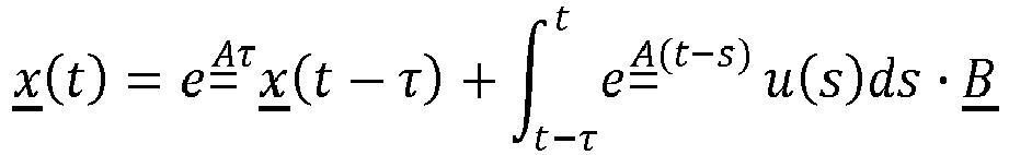

- This shows that the current reservoir state x (t) is a function of the reservoir state at the previous time step x (t - τ) and the input signal u(t) over the interval [t - τ, t]. Since the entire continuous interval is not available in software or digital hardware, in the digital cognitive radar processor, u(t) is approximated over the interval using linear basis functions.
- Referring also to
FIGS. 6A and 6B, FIG. 6A is an example of approximation of an input signal u(t) 600 using uniform sampling with sampling period Δt in accordance with an embodiment of the present disclosure.FIG. 6B is an example of using a linear basis function for approximation of the input signal u(t) 600 in accordance with another embodiment of the present disclosure. In these examples, input signal u(t) 600 corresponds to inputsignal 124. Given the sampling period Δt, u(t), a set of samples as follows:

-
FIG. 6A ). As shown inFIG. 6B , the input signal is approximated from the samples as

- Based on the linear basis approximation the DDE for the reservoir state x (t) becomes
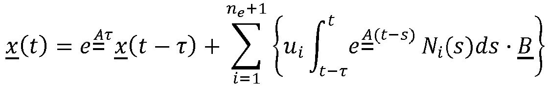
- Without loss of generality, set t = τ and two auxiliary matrices


- Then x (τ) can be computed as:

- Based on this, iterative updates are derived for the state ( x ), output (y), and weights, (

Algorithm 1 described below. Each required update step is achieved within one clock cycle without the need of waiting for a calculation step to be completed before a subsequent step can start. This enables a parallelized implementation of the de-noising algorithm. - Referring to
FIG. 7, FIG. 7 is a schematic diagram of an example acognitive radar processor 700 in accordance with an embodiment of the present disclosure. Thecognitive radar processor 700 shown inFIG. 7 is amenable to implementation on an FPGA or custom digital ASIC. -
Algorithm 1 is a cognitive signal de-noising iterative algorithm and includes the following operations: - Initialization:

- Iteration (starting at n = K + 2):
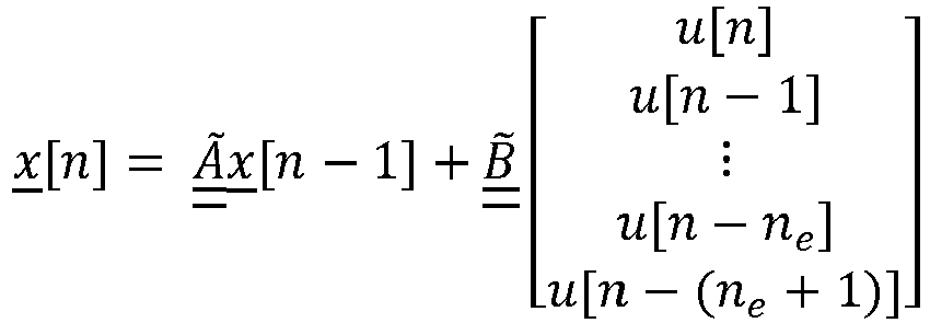


- In accordance with an embodiment, the discretized state-
space representation 142 for the time-varyingreservoir 128 is derived by assuming that Δt = τ, and consequently, ne = 1. Recalling fromAlgorithm 1 that the discretized state update equations for the dynamic reservoir with delay-embedded states is given by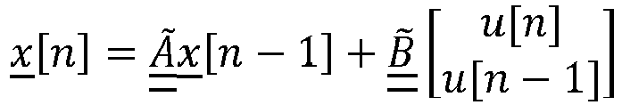

- Grouping together the current state vector with the past K delayed state vectors

- The phase delay embedding can be incorporated into the state-space representation of the dynamic reservoir:


- This shows that a linear reservoir with N nodes combined with the phase delay embedding of size K is a linear reservoir with (K + 1)N nodes where the state transition matrix  and input-to-reservoir map B́ have the above structured forms. The identity matrices are a computationally efficient mechanism for applying a static reservoir state transition matrix  to the
history 151 of thereservoir states 140a-140b. The time-varyingreservoir 128 is obtained by applying a different state transition matrix Ai for each delayed state x [n - i]:
reservoir 128 can be used to detect and de-noise non-stationary signals. - As an example, of how to design the time-varying
reservoir 128 for optimally de-noising linear chirp signals, the state transition matrix A 0 is constructed for the first sub-reservoir to have N = 2p poles distributed uniformly in some band of interest (e.g., between 10MHz and 500MHz) according to a Chebyshev low-pass filter prototype. The sub-reservoir specified by A 0 will have resonances at frequencies, f 1 ... fp. Matrices A 1 ... AK then have rows that are cyclically shifted versions of the rows of A 0. The jth row of the state transition matrix of Ai is given by:
- The sub-reservoirs specified by A 1 ... AK all have the same resonant frequencies as A 0, but are applied to different elements of the state vector. Thus, for a linear chirp signal u(t) =

reservoir 128 will detect and track this signal as it sweeps from frequency f 1 to frequency fp . Note that for the chirp-optimized reservoir, because each Ai is a permuted version of A 0, the computation of the reservoir state update is not significantly increased compared to the static reservoir. - The real-time de-noised time-varying
spectrogram 168 is provided using thede-noised reservoir states 170a-170n as previously described. Because thede-noised reservoir states 170a-170n are for a time-varyingreservoir 128, they can be interpreted as the response to a bank of time-varyingfilters 172. Thus, for the chirp-optimized reservoir described above, the set ofde-noised reservoir states 170a-170n form a chirplet spectrogram or real-time de-noised time-varyingspectrogram 168. This chirplet spectrogram or real-time de-noised time-varyingspectrogram 168 can be used for a variety of real-time signal analysis tasks, such as detection, separation of signals, and tracking of individual radar pulses within an input wideband signal mixture. - Mapping the
reservoir computer 126 output directly torange measurements 130 via thechirplet transform module 164 allows thecognitive radar processor 132 alone to function as the de-chirp, and detection functional blocks in state-of-the-art chirped radar implementations. As previously described, thede-noised reservoir states 170a-170n are interpreted as a bank of time-varyingfilters 172 at thechirp rate 106 set by the transmitchirp pulse 104. The response of the time-varyingfilters 172 to chirps received at different times are equivalent to the response of a bank of narrowband 1-pole IIR filters to different frequencies. This is precisely the function of the de-chirp functional block in traditional radar receivers. Therefore the different responses of thede-noised reservoir states 170a-170n representdifferent range measurements 130a-130n totargets 118a-118n reflecting the transmittedchirp pulses 104. - The
de-noised reservoir states 170a-170n represent relative range measurements ri inside the radar return receive window or time duration the receiver in on and able to receiving signals. The absolute range measurement can be computed from the delay between the transmit time TTx and the receive time TRx:

- The signal's signal-to-noise ratio (SNR) can be further increased through (effective) "pulse compression" by integrating (summing) the output of a single reservoir state (a single filter in the bank of time-varying filters 172) using
integration module 166 as previously described. Note that this demonstrates that the SNR increase due to the reservoir computer de-noising is in addition to the effective gain increase obtained by pulse compression in traditional radar applications. - Referring to
FIG. 8, FIG. 8 is an example of achirplet spectrogram 800 of a de-noised input signal in accordance with an embodiment of the present disclosure.FIG. 8 shows the chirplet transform read off from thede-noised reservoir states 170a-170n. The horizontal lines in a chirplet spectrogram or diagonal lines in astandard spectrogram 802 correspond to (simulated) received radar returns at the transmitchirp rate 106 of 31.831*10-6 fs2 where fs is the sample rate of the ADC. The y-axis represents the relative range measurements ri inside the radar return receive window. The absolute range measurement can be computed from the delay between the transmit time TTx and the receive time TRx using the equations for R0 and Ri above. As previously described, the signal's SNR can be further increased through (effective) pulse compression (integration along the x-axis). Note that this demonstrates that the SNR increase due to the reservoir computer de-noising is in addition to the effective gain increase obtained by pulse compression. -
FIG. 9 is a flow chart of an example of amethod 900 for measuring a range to each of a plurality of targets using a below-noise after transmit (BAT) Chirp Radar in accordance with an embodiment of the present disclosure. In accordance with an example, themethod 900 is embodied in and performed by thereservoir computer 126 orcognitive radar processor 132 inFIG. 1 . Accordingly, thereservoir computer 126 orcognitive radar processor 132 is configured to perform a set functions defined by themethod 900. - In
block 902, a noisy input signal is received by a cognitive radar processor. The noisy input signal includes a plurality of reflected RF signals or radar signals from a plurality of targets and noise. - In
block 904, predictive filtering including a time-varying reservoir is used to analyze the noisy input signal. Inblock 906, the noisy input signal is analyzed to separate a predictive signal pattern and an unpredictable noise pattern for identifying the unpredictable noise pattern. - In
block 908, an inverse noise signal is applied to the noisy input signal to cancel the unpredictable noise pattern. The inverse noise signal corresponds to the unpredictable noise pattern. - In
block 910, an enhanced RF signal or return radar signal is generated in response to cancelling the unpredictable noise pattern from the predictive signal pattern. - In
block 912, the enhanced RF signal or return radar signal is mapped to range measurements for each of the targets. -
FIG. 10 is a flow chart of an example of amethod 1000 for measuring a range to each of a plurality of targets using a below-noise after transmit (BAT) Chirp Radar in accordance with another embodiment of the present disclosure. In accordance with an example, themethod 1000 is embodied in and performed by thereservoir computer 126 orcognitive radar processor 132 inFIG. 1 . Accordingly, thereservoir computer 126 orcognitive radar processor 132 is configured to perform a set functions defined by themethod 1000. - In
block 1002, a noisy input signal is received. In accordance with the exemplary embodiment inFIG. 1 , thenoisy input signal 124 is a time-series of data points from a plurality of reflectedsignals 116a-116n sampled from a bandwidth greater than about 30 GHz. Although other bandwidths may also be sampled. - In
block 1004, the noisy input signal is linearly mapped into a time-varying reservoir. The time-varying reservoir includes a multiplicity of time-varying reservoir states. Inblock 1006, a high-dimensional state-space representation or multi-dimensional state-space representation of the reflected signals is created by combining the noisy input signal with the time-varying reservoir states of the time-varying reservoir. - In
block 1008, a delay embedded reservoir state signal is generated from each time-varying reservoir state that provides a finite temporal record of the reservoir state dynamics or history of the time-varying reservoir states. - In
block 1010, each time-varying reservoir state is de-noised which corresponds to de-noising the noisy input signal so that noise is removed and signals corresponding to the reflected signals without noise remain. Inblock 1012, a real-time de-noised time-varying spectrogram of the noisy input signal is generated from the de-noised reservoir states or de-noised reservoir state signals. - In
block 1014, the de-noised time-varying spectrogram is integrated in an output layer of the cognitive radar processor. In block 1016, the integrated de-noised time-varying spectrogram is mapped to the range measurement for each of the plurality of targets. - Although specific embodiments have been illustrated and described herein, those of ordinary skill in the art appreciate that any arrangement which is calculated to achieve the same purpose may be substituted for the specific embodiments shown and that the embodiments have other applications in other environments. This application is intended to cover any adaptations or variations. The following claims are in no way intended to limit the scope of embodiments of the disclosure to the specific embodiments described herein.
Claims (7)
- A radar system (100), comprising:a transmit antenna (110) for transmitting a radio frequency (RF) signal (112) or a radar signal;a receive antenna (114) for receiving a plurality of reflected signals (116a-116n) created by a plurality of targets (118a-118n) reflecting the RF signal (112) or radar signal, the reflected signals comprising noise;an analog-to-digital converter, ADC, (122) that digitizes or samples the plurality of reflected signals to provide a digitized or sampled noisy input signal (124); anda reservoir computer (126) that receives the noisy input signal (124), the reservoir computer (126) comprising a time-varying reservoir (128) and being configured to de-noise the noisy input signal (124) and provide a range measurement (130) for each of the plurality of targets (118a-118n),wherein the RF signal or the radar signal comprises a chirped or step-chirped waveform (104a) at a chirp rate,wherein the reservoir computer (126) comprises a cognitive radar processor (132), and the cognitive radar processor (132) comprises the time-varying reservoir (128), the time-varying reservoir (128) comprising a multiplicity of time-varying reservoir states (140a-140n) and the time-varying reservoir (128) being configured to linearly map the noisy input signal (124) into respective reservoir states (140a-140n) to create a high-dimensional state-space representation (142) of the noisy input signal (124),wherein the cognitive radar processor (132) further comprises:a delay embedding module (136), the delay embedding module (136) being configured to receive a reservoir state signal (148a-148n) corresponding to each respective time-varying reservoir state (140a-140n) and to generate a delay embedded reservoir state signal (150a-150n) corresponding to each time-varying reservoir state (140a-140n) that represents a history of the time-varying reservoir states (151) or reservoir state dynamics over a short-time period based on a predetermined time delay (154) of the delay embedding module (136); anda weight adaptation module (138) that receives the delay embedded reservoir state signals (150a-150n), the weight adaptation module (138) being configured to produce a de-noised reservoir state signal (152a-152n) for each time-varying reservoir state (140a-140n) or reservoir state signal (148a-148n), the de-noised reservoir state signals corresponding to the noisy input signal (124) being de-noised to provide a de-noised input signal (158),wherein the weight adaptation module (138) is configured to produce a prediction (156) of the noisy input signal at a predetermined future time from the delay embedded reservoir state signals (150a-150n) and to use the prediction (156) of the noisy input signal (124) to de-noise each reservoir state signal (148a-148n) using a gradient descent learning algorithm (160), wherein weights (162a-162n) of the weight adaptation module (138) are determined using the gradient descent learning algorithm (160),wherein the cognitive radar processor (132) further comprises a chirplet transform module (164) configured to receive the de-noised reservoir state signals (152a-152n), corresponding to the de-noised input signal (158), from the weight adaptation module (138), and to generate a real-time de-noised spectrogram (168) of the de-noised input signal (158) representing the reflected signals (116a-116n) from the plurality of targets (118a-118n), wherein the chirplet transform module (164) is configured to map each of de-noised reservoir states (170a-170n) or the de-noised reservoir state signals (152a-152n) to the range measurement (130a-130n) of each of the plurality of targets (118a-118n), andwherein the de-noised reservoir states (170a-170n) define a bank of time-varying filters (172) at a chirp rate (106) set by a transmit chirp (104) of the RF signal (112) or the radar signal, wherein a response of the time-varying filters (172) to chirps received at different times are equivalent to a response of a bank of 1-pole infinite impulse response, IIR, filters to different frequencies.
- The radar system of claim 1, further comprising an integration module (166) for integrating the real-time de-noised spectrogram (168) of the de-noised input signal (158) to create an integrated de-noised spectrogram (174) and mapping the integrated de-noised spectrogram (174) to the range measurements (130a-130n), wherein the integration module (166) is configured to increase a signal-to-noise ratio of each de-noised reservoir state signal (152a-152n) by pulse compression comprising integrating or summing an output (178a-178n) of each de-noised reservoir state signal (152a-152n).
- The radar system of claim 1, wherein the time-varying reservoir (128) comprises a recurrent neural network (402) comprising a plurality of nodes (402), each node (402) corresponding to one of the time-varying reservoir states (140a-140n).
- The radar system of claim 3, wherein the time-varying reservoir comprises a state transition matrix comprising a predetermined block diagonal structure that is optimized for signal de-noising and efficient implementation in hardware.
- The radar system of claim 4, wherein the delay embedding module comprises a delay embedded reservoir state vector that has a different state transition matrix to enable time-varying dynamics.
- A cognitive radar processor (132), comprising:a time-varying reservoir (128), the time-varying reservoir (128) comprising a multiplicity of time-varying reservoir states (140a-140n) and the time-varying reservoir being configured to linearly map a noisy input signal (124) into respective reservoir states (140a-140n) to create a high-dimensional state-space representation (142) of the noisy input signal (124), the noisy input signal resulting from a radio frequency, RF, signal (112) or radar signal reflected by a plurality of targets (118a - 118n);a delay embedding module (136), the delay embedding module (136) being configured to receive a reservoir state signal (148a-148n) corresponding to each respective time-varying reservoir state (140a-140n) and to generate a delay embedded reservoir state signal (150a-150n) corresponding to each time-varying reservoir state (140a-140n) that represents a history (151) of the time-varying reservoir states or reservoir state dynamics over a short-time period based on a predetermined time delay (154) of the delay embedding module (136); anda weight adaptation module (138) that receives the delay embedded reservoir state signals (150a-150n), the weight adaptation module (138) being configured to produce a de-noised reservoir state signal (152a-152n) for each reservoir state (140a-140n) or reservoir state signal (148a-148n), the de-noised reservoir state signals (152a-152n) corresponding to the noisy input signal (124) being de-noised to provide a de-noised input signal (158),wherein the weight adaptation module (138) is configured to produce a prediction (156) of the noisy input signal at a predetermined future time from the delay embedded reservoir state signals (150a-150n) and to use the prediction (156) of the noisy input signal to de-noise each reservoir state signal (148a-148n) using a gradient descent learning algorithm (160), wherein weights (162a-162n) of the weight adaptation module (138) are determined using the gradient descent learning algorithm (160),wherein the cognitive radar processor (132) further comprises a chirplet transform module (164) configured to receive the de-noised reservoir state signals (152a-152n), corresponding to the de-noised input signal (158), from the weight adaptation module (138) and to generate a real-time de-noised spectrogram (168) of the de-noised input signal (158) representing reflected signals (116a-116n) from a plurality of targets (118a-118n), wherein the chirplet transform module (164) is configured to map each of de-noised reservoir states (170a-170n) or the de-noised reservoir state signals (152a-152n) to a range measurement (130a-130n) of each of the plurality of targets (118a-118n), andwherein the de-noised reservoir states (170a-170n) define a bank of time-varying filters (172) at a chirp rate (106) set by a transmit chirp (104) of the RF signal (112) or the radar signal, wherein a response of the time-varying filters (172) to chirps received at different times are equivalent to a response of a bank of 1-pole infinite impulse response, IIR, filters to different frequencies.
- The cognitive radar processor of claim 6, further comprising an integration module for integrating the real-time de-noised spectrogram of the de-noised input signal to create an integrated de-noised spectrogram and mapping the integrated de-noised spectrogram to the range measurements, wherein the integration module is configured to increase a signal-to-noise ratio of each de-noised reservoir state signal by pulse compression comprising integrating or summing an output of each de-noised reservoir state signal.
Applications Claiming Priority (2)
| Application Number | Priority Date | Filing Date | Title |
|---|---|---|---|
| US201762577076P | 2017-10-25 | 2017-10-25 | |
| US15/885,344 US10921422B2 (en) | 2017-10-25 | 2018-01-31 | Below-noise after transmit (BAT) Chirp Radar |
Publications (2)
| Publication Number | Publication Date |
|---|---|
| EP3477331A1 EP3477331A1 (en) | 2019-05-01 |
| EP3477331B1 true EP3477331B1 (en) | 2024-09-04 |
Family
ID=63637704
Family Applications (1)
| Application Number | Title | Priority Date | Filing Date |
|---|---|---|---|
| EP18194748.2A Active EP3477331B1 (en) | 2017-10-25 | 2018-09-17 | Below-noise after transmit (bat) chirp radar |
Country Status (5)
| Country | Link |
|---|---|
| US (1) | US10921422B2 (en) |
| EP (1) | EP3477331B1 (en) |
| JP (1) | JP7258513B2 (en) |
| KR (1) | KR102736930B1 (en) |
| CN (1) | CN109709521B (en) |
Cited By (1)
| Publication number | Priority date | Publication date | Assignee | Title |
|---|---|---|---|---|
| US20250199112A1 (en) * | 2023-12-19 | 2025-06-19 | Nxp B.V. | Interference sensing and adaptation |
Families Citing this family (14)
| Publication number | Priority date | Publication date | Assignee | Title |
|---|---|---|---|---|
| US10783430B2 (en) | 2016-09-26 | 2020-09-22 | The Boeing Company | Signal removal to examine a spectrum of another signal |
| US11002819B2 (en) | 2018-04-24 | 2021-05-11 | The Boeing Company | Angular resolution of targets using separate radar receivers |
| US10962637B2 (en) * | 2018-06-25 | 2021-03-30 | Texas Instruments Incorporated | Radar data processing using neural network classifier and confidence metrics |
| US11609314B2 (en) * | 2018-08-02 | 2023-03-21 | Uatc, Llc | Lidar system design to mitigate Lidar cross-talk |
| US11448721B2 (en) * | 2019-06-25 | 2022-09-20 | Infineon Technologies Ag | In device interference mitigation using sensor fusion |
| CN110687519B (en) * | 2019-11-12 | 2024-08-20 | 武汉万集光电技术有限公司 | Laser radar signal noise reduction device and method |
| US12499355B1 (en) * | 2020-07-13 | 2025-12-16 | Hrl Laboratories, Llc | Complex neuromorphic adaptive core (neuracore) and physics enhanced neuromorphic adaptive controller |
| US12057989B1 (en) * | 2020-07-14 | 2024-08-06 | Hrl Laboratories, Llc | Ultra-wide instantaneous bandwidth complex neuromorphic adaptive core processor |
| US11863221B1 (en) * | 2020-07-14 | 2024-01-02 | Hrl Laboratories, Llc | Low size, weight and power (swap) efficient hardware implementation of a wide instantaneous bandwidth neuromorphic adaptive core (NeurACore) |
| CN113391285B (en) * | 2021-05-25 | 2024-03-08 | 西安理工大学 | A smoothing method for target tracking with flicker noise measured under random delay |
| US12111385B2 (en) * | 2021-12-23 | 2024-10-08 | Gm Cruise Holdings Llc | Radar sensor processing chain |
| US12366655B2 (en) | 2022-05-17 | 2025-07-22 | Rockwell Collins, Inc. | Reprogrammable radar system and method |
| WO2024116229A1 (en) * | 2022-11-28 | 2024-06-06 | Tdk株式会社 | Signal processing device |
| CN115830455B (en) * | 2022-12-23 | 2026-01-02 | 电子科技大学 | A feature extraction method for multi-rotor UAVs and bird targets |
Family Cites Families (48)
| Publication number | Priority date | Publication date | Assignee | Title |
|---|---|---|---|---|
| US7164117B2 (en) * | 1992-05-05 | 2007-01-16 | Automotive Technologies International, Inc. | Vehicular restraint system control system and method using multiple optical imagers |
| US5402520A (en) * | 1992-03-06 | 1995-03-28 | Schnitta; Bonnie S. | Neural network method and apparatus for retrieving signals embedded in noise and analyzing the retrieved signals |
| US5499029A (en) * | 1992-07-14 | 1996-03-12 | Eg&G Energy Measurements, Inc. | Wide band stepped frequency ground penetrating radar |
| US5325095A (en) * | 1992-07-14 | 1994-06-28 | The United States Of America As Represented By The United States Department Of Energy | Stepped frequency ground penetrating radar |
| US5504487A (en) * | 1995-05-17 | 1996-04-02 | Fastman, Inc. | System for extracting targets from radar signatures |
| US5694474A (en) | 1995-09-18 | 1997-12-02 | Interval Research Corporation | Adaptive filter for signal processing and method therefor |
| US6691073B1 (en) * | 1998-06-18 | 2004-02-10 | Clarity Technologies Inc. | Adaptive state space signal separation, discrimination and recovery |
| US7474756B2 (en) * | 2002-12-18 | 2009-01-06 | Siemens Corporate Research, Inc. | System and method for non-square blind source separation under coherent noise by beamforming and time-frequency masking |
| US7333850B2 (en) | 2004-05-28 | 2008-02-19 | University Of Florida Research Foundation, Inc. | Maternal-fetal monitoring system |
| US8031117B2 (en) * | 2004-09-23 | 2011-10-04 | Interdigital Technology Corporation | Blind signal separation using polarized antenna elements |
| WO2006084307A1 (en) * | 2005-02-09 | 2006-08-17 | Reeves Bayan Anthony | Radar system |
| US9070101B2 (en) * | 2007-01-12 | 2015-06-30 | Fatdoor, Inc. | Peer-to-peer neighborhood delivery multi-copter and method |
| US7403144B1 (en) | 2006-12-26 | 2008-07-22 | Hrl Laboratories, Llc | Pulse domain encoder and filter circuits |
| US7822698B1 (en) | 2007-03-23 | 2010-10-26 | Hrl Laboratories, Llc | Spike domain and pulse domain non-linear processors |
| US8126642B2 (en) * | 2008-10-24 | 2012-02-28 | Gray & Company, Inc. | Control and systems for autonomously driven vehicles |
| US8468108B1 (en) * | 2009-06-30 | 2013-06-18 | Zytek Communications Corporation | Modeling efficiency over a range of velocities in underwater vehicles |
| EP2478835B1 (en) | 2009-09-18 | 2018-01-10 | Tohoku University | Signal extracting apparatus, method and computer program |
| US8515335B2 (en) * | 2009-11-30 | 2013-08-20 | The Aerospace Corporation | Cognitive anti-jam receiver systems and associated methods |
| US8566265B1 (en) | 2011-03-10 | 2013-10-22 | Hrl Laboratories, Llc | Combined spike domain and pulse domain signal processing |
| US8861588B2 (en) * | 2011-04-04 | 2014-10-14 | The United States Of America As Represented By The Secretary Of The Army | Apparatus and method for sampling and reconstruction of wide bandwidth signals below Nyquist rate |
| US8743658B2 (en) * | 2011-04-29 | 2014-06-03 | Siemens Corporation | Systems and methods for blind localization of correlated sources |
| US9024815B2 (en) * | 2011-05-27 | 2015-05-05 | Brooks Engineering International, Llc | Direct-to-digital software-defined radar |
| CN102281221B (en) | 2011-06-23 | 2017-03-15 | 中兴通讯股份有限公司 | Nonlinear systematic distortion correction device and method |
| US8977578B1 (en) | 2012-06-27 | 2015-03-10 | Hrl Laboratories, Llc | Synaptic time multiplexing neuromorphic network that forms subsets of connections during different time slots |
| US8959040B1 (en) | 2012-03-08 | 2015-02-17 | Hrl Laboratories, Llc | Spike timing dependent plasticity apparatus, system and method |
| US10497381B2 (en) * | 2012-05-04 | 2019-12-03 | Xmos Inc. | Methods and systems for improved measurement, entity and parameter estimation, and path propagation effect measurement and mitigation in source signal separation |
| WO2013166439A1 (en) * | 2012-05-04 | 2013-11-07 | Setem Technologies, Llc | Systems and methods for source signal separation |
| US20140114442A1 (en) | 2012-10-22 | 2014-04-24 | The Boeing Company | Real time control system management |
| US9042496B1 (en) * | 2013-02-19 | 2015-05-26 | The United States Of America, As Represented By The Secretary Of The Army | Signal modulation scheme determination through an at least fourth-order noise-insensitive cumulant |
| US20150202770A1 (en) * | 2014-01-17 | 2015-07-23 | Anthony Patron | Sidewalk messaging of an autonomous robot |
| US9986934B2 (en) * | 2014-01-29 | 2018-06-05 | California Institute Of Technology | Microwave radar sensor modules |
| WO2015162605A2 (en) * | 2014-04-22 | 2015-10-29 | Snapaid Ltd | System and method for controlling a camera based on processing an image captured by other camera |
| US10222454B2 (en) * | 2014-08-19 | 2019-03-05 | Navico Holding As | Combining Reflected Signals |
| US9484974B2 (en) | 2014-09-10 | 2016-11-01 | Qualcomm Incorporated | Methods and systems for multi-layer perceptron based non-linear interference management in multi-technology communication devices |
| JP6548376B2 (en) * | 2014-10-06 | 2019-07-24 | 日本電産株式会社 | Radar system, radar signal processing device, vehicle travel control device and method, and computer program |
| CN105704075A (en) | 2014-11-25 | 2016-06-22 | 中兴通讯股份有限公司 | Correction processing method and correction processing device |
| US10540957B2 (en) * | 2014-12-15 | 2020-01-21 | Baidu Usa Llc | Systems and methods for speech transcription |
| DE102015100804B4 (en) * | 2015-01-20 | 2016-11-17 | Infineon Technologies Ag | Radar device with noise reduction |
| US10054668B2 (en) * | 2015-02-26 | 2018-08-21 | Src, Inc. | Probabilistic signal, detection, and track processing architecture and system |
| US9749007B1 (en) * | 2015-03-19 | 2017-08-29 | Hrl Laboratories, Llc | Cognitive blind source separator |
| DE102015120733B4 (en) * | 2015-11-30 | 2017-11-02 | Infineon Technologies Ag | Radar device with phase noise estimation |
| US10539645B2 (en) | 2016-01-22 | 2020-01-21 | GM Global Technology Operations LLC | Angle of arrival estimation |
| WO2017187306A1 (en) * | 2016-04-25 | 2017-11-02 | Uhnder, Inc. | Adaptive filtering for fmcw interference mitigation in pmcw radar systems |
| US9753121B1 (en) * | 2016-06-20 | 2017-09-05 | Uhnder, Inc. | Power control for improved near-far performance of radar systems |
| US10783430B2 (en) | 2016-09-26 | 2020-09-22 | The Boeing Company | Signal removal to examine a spectrum of another signal |
| US10832168B2 (en) * | 2017-01-10 | 2020-11-10 | Crowdstrike, Inc. | Computational modeling and classification of data streams |
| WO2018136144A1 (en) | 2017-01-18 | 2018-07-26 | Hrl Laboratories, Llc | Cognitive signal processor for simultaneous denoising and blind source separation |
| US11002819B2 (en) | 2018-04-24 | 2021-05-11 | The Boeing Company | Angular resolution of targets using separate radar receivers |
-
2018
- 2018-01-31 US US15/885,344 patent/US10921422B2/en active Active
- 2018-09-17 EP EP18194748.2A patent/EP3477331B1/en active Active
- 2018-10-02 KR KR1020180117790A patent/KR102736930B1/en active Active
- 2018-10-23 JP JP2018198838A patent/JP7258513B2/en active Active
- 2018-10-24 CN CN201811245784.9A patent/CN109709521B/en active Active
Cited By (1)
| Publication number | Priority date | Publication date | Assignee | Title |
|---|---|---|---|---|
| US20250199112A1 (en) * | 2023-12-19 | 2025-06-19 | Nxp B.V. | Interference sensing and adaptation |
Also Published As
| Publication number | Publication date |
|---|---|
| CN109709521A (en) | 2019-05-03 |
| CN109709521B (en) | 2024-09-06 |
| KR20190046632A (en) | 2019-05-07 |
| US20190120932A1 (en) | 2019-04-25 |
| JP7258513B2 (en) | 2023-04-17 |
| KR102736930B1 (en) | 2024-12-02 |
| US10921422B2 (en) | 2021-02-16 |
| JP2019090795A (en) | 2019-06-13 |
| EP3477331A1 (en) | 2019-05-01 |
Similar Documents
| Publication | Publication Date | Title |
|---|---|---|
| EP3477331B1 (en) | Below-noise after transmit (bat) chirp radar | |
| US10404299B1 (en) | System for parallelized cognitive signal denoising | |
| US10153806B1 (en) | Cognitive architecture for wideband, low-power, real-time signal denoising | |
| CN110088635B (en) | Cognitive signal processor, method and medium for denoising and blind source separation | |
| US10128820B2 (en) | Cognitive signal processor for simultaneous denoising and blind source separation | |
| US10720949B1 (en) | Real-time time-difference-of-arrival (TDOA) estimation via multi-input cognitive signal processor | |
| EP3561539B1 (en) | Angular resolution of targets using separate radar receivers | |
| US12204490B2 (en) | Pipelined cognitive signal processor | |
| US11037057B1 (en) | Cognitive signal processor | |
| CN104215959B (en) | Method for estimating radial initial speeds and radial acceleration of multiple maneuvering targets | |
| CN110954883B (en) | Non-parameter iteration self-adaption-based agile radar target reconstruction method | |
| Li et al. | Fast pseudospectrum estimation for automotive massive MIMO radar | |
| Khobahi et al. | Deep radar waveform design for efficient automotive radar sensing | |
| US10380062B1 (en) | Efficient cognitive signal denoising with sparse output layers | |
| US10712425B1 (en) | Cognitive denoising of nonstationary signals using time varying reservoir computer | |
| US20220222512A1 (en) | Systems and methods for cognitive signal processing | |
| CN117269913A (en) | A coherent accumulation detection method for UAV targets based on Bayesian compressed sensing | |
| Volz et al. | Inverse filtering of radar signals using compressed sensing with application to meteors | |
| Huang et al. | Real-beam scanning radar angular super-resolution via sparse deconvolution | |
| Lu et al. | Robust direction of arrival estimation approach for unmanned aerial vehicles at low signal‐to‐noise ratios | |
| CN104698444B (en) | Method for determining influences of array element position errors on three-dimensional imaging quality of array antenna | |
| CN105303009A (en) | Super-resolution spectrum estimation method based on compressed sensing and regular MFOCUSS | |
| Petrov et al. | Fast implementation of iterative adaptive approach for wideband unambiguous radar detection | |
| Jonsson | Quantum and classical metrology for noise radar | |
| Tserne et al. | Methodology of statistical synthesis and analysis methods for stochastic signal processing in multi-antenna radio direction finders |
Legal Events
| Date | Code | Title | Description |
|---|---|---|---|
| PUAI | Public reference made under article 153(3) epc to a published international application that has entered the european phase |
Free format text: ORIGINAL CODE: 0009012 |
|
| STAA | Information on the status of an ep patent application or granted ep patent |
Free format text: STATUS: THE APPLICATION HAS BEEN PUBLISHED |
|
| AK | Designated contracting states |
Kind code of ref document: A1 Designated state(s): AL AT BE BG CH CY CZ DE DK EE ES FI FR GB GR HR HU IE IS IT LI LT LU LV MC MK MT NL NO PL PT RO RS SE SI SK SM TR |
|
| AX | Request for extension of the european patent |
Extension state: BA ME |
|
| STAA | Information on the status of an ep patent application or granted ep patent |
Free format text: STATUS: REQUEST FOR EXAMINATION WAS MADE |
|
| 17P | Request for examination filed |
Effective date: 20191018 |
|
| RBV | Designated contracting states (corrected) |
Designated state(s): AL AT BE BG CH CY CZ DE DK EE ES FI FR GB GR HR HU IE IS IT LI LT LU LV MC MK MT NL NO PL PT RO RS SE SI SK SM TR |
|
| STAA | Information on the status of an ep patent application or granted ep patent |
Free format text: STATUS: EXAMINATION IS IN PROGRESS |
|
| 17Q | First examination report despatched |
Effective date: 20210526 |
|
| RAP3 | Party data changed (applicant data changed or rights of an application transferred) |
Owner name: HRL LABORATORIES, LLC Owner name: THE BOEING COMPANY |
|
| GRAP | Despatch of communication of intention to grant a patent |
Free format text: ORIGINAL CODE: EPIDOSNIGR1 |
|
| STAA | Information on the status of an ep patent application or granted ep patent |
Free format text: STATUS: GRANT OF PATENT IS INTENDED |
|
| RIC1 | Information provided on ipc code assigned before grant |
Ipc: G01S 13/87 20060101ALN20240306BHEP Ipc: G01S 13/931 20200101ALN20240306BHEP Ipc: G06N 3/084 20230101ALI20240306BHEP Ipc: G06N 3/044 20230101ALI20240306BHEP Ipc: G06F 18/2413 20230101ALI20240306BHEP Ipc: G06F 18/2134 20230101ALI20240306BHEP Ipc: G01S 13/34 20060101ALI20240306BHEP Ipc: G01S 13/26 20060101ALI20240306BHEP Ipc: G01S 13/02 20060101ALI20240306BHEP Ipc: G01S 13/00 20060101ALI20240306BHEP Ipc: G01S 7/35 20060101ALI20240306BHEP Ipc: G01S 7/292 20060101ALI20240306BHEP Ipc: G01S 7/41 20060101AFI20240306BHEP |
|
| RIC1 | Information provided on ipc code assigned before grant |
Ipc: G01S 13/87 20060101ALN20240309BHEP Ipc: G01S 13/931 20200101ALN20240309BHEP Ipc: G06N 3/084 20230101ALI20240309BHEP Ipc: G06N 3/044 20230101ALI20240309BHEP Ipc: G06F 18/2413 20230101ALI20240309BHEP Ipc: G06F 18/2134 20230101ALI20240309BHEP Ipc: G01S 13/34 20060101ALI20240309BHEP Ipc: G01S 13/26 20060101ALI20240309BHEP Ipc: G01S 13/02 20060101ALI20240309BHEP Ipc: G01S 13/00 20060101ALI20240309BHEP Ipc: G01S 7/35 20060101ALI20240309BHEP Ipc: G01S 7/292 20060101ALI20240309BHEP Ipc: G01S 7/41 20060101AFI20240309BHEP |
|
| INTG | Intention to grant announced |
Effective date: 20240408 |
|
| GRAS | Grant fee paid |
Free format text: ORIGINAL CODE: EPIDOSNIGR3 |
|
| GRAA | (expected) grant |
Free format text: ORIGINAL CODE: 0009210 |
|
| STAA | Information on the status of an ep patent application or granted ep patent |
Free format text: STATUS: THE PATENT HAS BEEN GRANTED |
|
| AK | Designated contracting states |
Kind code of ref document: B1 Designated state(s): AL AT BE BG CH CY CZ DE DK EE ES FI FR GB GR HR HU IE IS IT LI LT LU LV MC MK MT NL NO PL PT RO RS SE SI SK SM TR |
|
| P01 | Opt-out of the competence of the unified patent court (upc) registered |
Free format text: CASE NUMBER: APP_43715/2024 Effective date: 20240726 |
|
| REG | Reference to a national code |
Ref country code: GB Ref legal event code: FG4D |
|
| REG | Reference to a national code |
Ref country code: CH Ref legal event code: EP |
|
| REG | Reference to a national code |
Ref country code: IE Ref legal event code: FG4D |
|
| REG | Reference to a national code |
Ref country code: DE Ref legal event code: R096 Ref document number: 602018073877 Country of ref document: DE |
|
| REG | Reference to a national code |
Ref country code: LT Ref legal event code: MG9D |
|
| REG | Reference to a national code |
Ref country code: NL Ref legal event code: MP Effective date: 20240904 |
|
| PG25 | Lapsed in a contracting state [announced via postgrant information from national office to epo] |
Ref country code: NO Free format text: LAPSE BECAUSE OF FAILURE TO SUBMIT A TRANSLATION OF THE DESCRIPTION OR TO PAY THE FEE WITHIN THE PRESCRIBED TIME-LIMIT Effective date: 20241204 |
|
| PG25 | Lapsed in a contracting state [announced via postgrant information from national office to epo] |
Ref country code: FI Free format text: LAPSE BECAUSE OF FAILURE TO SUBMIT A TRANSLATION OF THE DESCRIPTION OR TO PAY THE FEE WITHIN THE PRESCRIBED TIME-LIMIT Effective date: 20240904 Ref country code: GR Free format text: LAPSE BECAUSE OF FAILURE TO SUBMIT A TRANSLATION OF THE DESCRIPTION OR TO PAY THE FEE WITHIN THE PRESCRIBED TIME-LIMIT Effective date: 20241205 Ref country code: PL Free format text: LAPSE BECAUSE OF FAILURE TO SUBMIT A TRANSLATION OF THE DESCRIPTION OR TO PAY THE FEE WITHIN THE PRESCRIBED TIME-LIMIT Effective date: 20240904 |
|
| PG25 | Lapsed in a contracting state [announced via postgrant information from national office to epo] |
Ref country code: BG Free format text: LAPSE BECAUSE OF FAILURE TO SUBMIT A TRANSLATION OF THE DESCRIPTION OR TO PAY THE FEE WITHIN THE PRESCRIBED TIME-LIMIT Effective date: 20240904 |
|
| PG25 | Lapsed in a contracting state [announced via postgrant information from national office to epo] |
Ref country code: LV Free format text: LAPSE BECAUSE OF FAILURE TO SUBMIT A TRANSLATION OF THE DESCRIPTION OR TO PAY THE FEE WITHIN THE PRESCRIBED TIME-LIMIT Effective date: 20240904 |
|
| PG25 | Lapsed in a contracting state [announced via postgrant information from national office to epo] |
Ref country code: HR Free format text: LAPSE BECAUSE OF FAILURE TO SUBMIT A TRANSLATION OF THE DESCRIPTION OR TO PAY THE FEE WITHIN THE PRESCRIBED TIME-LIMIT Effective date: 20240904 |
|
| PG25 | Lapsed in a contracting state [announced via postgrant information from national office to epo] |
Ref country code: ES Free format text: LAPSE BECAUSE OF FAILURE TO SUBMIT A TRANSLATION OF THE DESCRIPTION OR TO PAY THE FEE WITHIN THE PRESCRIBED TIME-LIMIT Effective date: 20240904 Ref country code: RS Free format text: LAPSE BECAUSE OF FAILURE TO SUBMIT A TRANSLATION OF THE DESCRIPTION OR TO PAY THE FEE WITHIN THE PRESCRIBED TIME-LIMIT Effective date: 20241204 |
|
| PG25 | Lapsed in a contracting state [announced via postgrant information from national office to epo] |
Ref country code: RS Free format text: LAPSE BECAUSE OF FAILURE TO SUBMIT A TRANSLATION OF THE DESCRIPTION OR TO PAY THE FEE WITHIN THE PRESCRIBED TIME-LIMIT Effective date: 20241204 Ref country code: PL Free format text: LAPSE BECAUSE OF FAILURE TO SUBMIT A TRANSLATION OF THE DESCRIPTION OR TO PAY THE FEE WITHIN THE PRESCRIBED TIME-LIMIT Effective date: 20240904 Ref country code: NO Free format text: LAPSE BECAUSE OF FAILURE TO SUBMIT A TRANSLATION OF THE DESCRIPTION OR TO PAY THE FEE WITHIN THE PRESCRIBED TIME-LIMIT Effective date: 20241204 Ref country code: LV Free format text: LAPSE BECAUSE OF FAILURE TO SUBMIT A TRANSLATION OF THE DESCRIPTION OR TO PAY THE FEE WITHIN THE PRESCRIBED TIME-LIMIT Effective date: 20240904 Ref country code: HR Free format text: LAPSE BECAUSE OF FAILURE TO SUBMIT A TRANSLATION OF THE DESCRIPTION OR TO PAY THE FEE WITHIN THE PRESCRIBED TIME-LIMIT Effective date: 20240904 Ref country code: GR Free format text: LAPSE BECAUSE OF FAILURE TO SUBMIT A TRANSLATION OF THE DESCRIPTION OR TO PAY THE FEE WITHIN THE PRESCRIBED TIME-LIMIT Effective date: 20241205 Ref country code: FI Free format text: LAPSE BECAUSE OF FAILURE TO SUBMIT A TRANSLATION OF THE DESCRIPTION OR TO PAY THE FEE WITHIN THE PRESCRIBED TIME-LIMIT Effective date: 20240904 Ref country code: ES Free format text: LAPSE BECAUSE OF FAILURE TO SUBMIT A TRANSLATION OF THE DESCRIPTION OR TO PAY THE FEE WITHIN THE PRESCRIBED TIME-LIMIT Effective date: 20240904 Ref country code: BG Free format text: LAPSE BECAUSE OF FAILURE TO SUBMIT A TRANSLATION OF THE DESCRIPTION OR TO PAY THE FEE WITHIN THE PRESCRIBED TIME-LIMIT Effective date: 20240904 |
|
| REG | Reference to a national code |
Ref country code: AT Ref legal event code: MK05 Ref document number: 1720930 Country of ref document: AT Kind code of ref document: T Effective date: 20240904 |
|
| PG25 | Lapsed in a contracting state [announced via postgrant information from national office to epo] |
Ref country code: NL Free format text: LAPSE BECAUSE OF FAILURE TO SUBMIT A TRANSLATION OF THE DESCRIPTION OR TO PAY THE FEE WITHIN THE PRESCRIBED TIME-LIMIT Effective date: 20240904 |
|
| REG | Reference to a national code |
Ref country code: DE Ref legal event code: R119 Ref document number: 602018073877 Country of ref document: DE |
|
| PG25 | Lapsed in a contracting state [announced via postgrant information from national office to epo] |
Ref country code: IS Free format text: LAPSE BECAUSE OF FAILURE TO SUBMIT A TRANSLATION OF THE DESCRIPTION OR TO PAY THE FEE WITHIN THE PRESCRIBED TIME-LIMIT Effective date: 20250104 Ref country code: PT Free format text: LAPSE BECAUSE OF FAILURE TO SUBMIT A TRANSLATION OF THE DESCRIPTION OR TO PAY THE FEE WITHIN THE PRESCRIBED TIME-LIMIT Effective date: 20250106 |
|
| PG25 | Lapsed in a contracting state [announced via postgrant information from national office to epo] |
Ref country code: RO Free format text: LAPSE BECAUSE OF FAILURE TO SUBMIT A TRANSLATION OF THE DESCRIPTION OR TO PAY THE FEE WITHIN THE PRESCRIBED TIME-LIMIT Effective date: 20240904 Ref country code: SM Free format text: LAPSE BECAUSE OF FAILURE TO SUBMIT A TRANSLATION OF THE DESCRIPTION OR TO PAY THE FEE WITHIN THE PRESCRIBED TIME-LIMIT Effective date: 20240904 |
|
| PG25 | Lapsed in a contracting state [announced via postgrant information from national office to epo] |
Ref country code: EE Free format text: LAPSE BECAUSE OF FAILURE TO SUBMIT A TRANSLATION OF THE DESCRIPTION OR TO PAY THE FEE WITHIN THE PRESCRIBED TIME-LIMIT Effective date: 20240904 Ref country code: AT Free format text: LAPSE BECAUSE OF FAILURE TO SUBMIT A TRANSLATION OF THE DESCRIPTION OR TO PAY THE FEE WITHIN THE PRESCRIBED TIME-LIMIT Effective date: 20240904 |
|
| PG25 | Lapsed in a contracting state [announced via postgrant information from national office to epo] |
Ref country code: CZ Free format text: LAPSE BECAUSE OF FAILURE TO SUBMIT A TRANSLATION OF THE DESCRIPTION OR TO PAY THE FEE WITHIN THE PRESCRIBED TIME-LIMIT Effective date: 20240904 |
|
| PG25 | Lapsed in a contracting state [announced via postgrant information from national office to epo] |
Ref country code: IT Free format text: LAPSE BECAUSE OF FAILURE TO SUBMIT A TRANSLATION OF THE DESCRIPTION OR TO PAY THE FEE WITHIN THE PRESCRIBED TIME-LIMIT Effective date: 20240904 Ref country code: SK Free format text: LAPSE BECAUSE OF FAILURE TO SUBMIT A TRANSLATION OF THE DESCRIPTION OR TO PAY THE FEE WITHIN THE PRESCRIBED TIME-LIMIT Effective date: 20240904 |
|
| REG | Reference to a national code |
Ref country code: CH Ref legal event code: PL |
|
| PG25 | Lapsed in a contracting state [announced via postgrant information from national office to epo] |
Ref country code: LU Free format text: LAPSE BECAUSE OF NON-PAYMENT OF DUE FEES Effective date: 20240917 |
|
| PG25 | Lapsed in a contracting state [announced via postgrant information from national office to epo] |
Ref country code: MC Free format text: LAPSE BECAUSE OF FAILURE TO SUBMIT A TRANSLATION OF THE DESCRIPTION OR TO PAY THE FEE WITHIN THE PRESCRIBED TIME-LIMIT Effective date: 20240904 |
|
| PG25 | Lapsed in a contracting state [announced via postgrant information from national office to epo] |
Ref country code: DE Free format text: LAPSE BECAUSE OF NON-PAYMENT OF DUE FEES Effective date: 20250401 |
|
| PG25 | Lapsed in a contracting state [announced via postgrant information from national office to epo] |
Ref country code: DK Free format text: LAPSE BECAUSE OF FAILURE TO SUBMIT A TRANSLATION OF THE DESCRIPTION OR TO PAY THE FEE WITHIN THE PRESCRIBED TIME-LIMIT Effective date: 20240904 |
|
| REG | Reference to a national code |
Ref country code: BE Ref legal event code: MM Effective date: 20240930 |
|
| PLBE | No opposition filed within time limit |
Free format text: ORIGINAL CODE: 0009261 |
|
| STAA | Information on the status of an ep patent application or granted ep patent |
Free format text: STATUS: NO OPPOSITION FILED WITHIN TIME LIMIT |
|
| PG25 | Lapsed in a contracting state [announced via postgrant information from national office to epo] |
Ref country code: BE Free format text: LAPSE BECAUSE OF NON-PAYMENT OF DUE FEES Effective date: 20240930 |
|
| PG25 | Lapsed in a contracting state [announced via postgrant information from national office to epo] |
Ref country code: CH Free format text: LAPSE BECAUSE OF NON-PAYMENT OF DUE FEES Effective date: 20240930 |
|
| PG25 | Lapsed in a contracting state [announced via postgrant information from national office to epo] |
Ref country code: IE Free format text: LAPSE BECAUSE OF NON-PAYMENT OF DUE FEES Effective date: 20240917 |
|
| 26N | No opposition filed |
Effective date: 20250605 |
|
| GBPC | Gb: european patent ceased through non-payment of renewal fee |
Effective date: 20241204 |
|
| PG25 | Lapsed in a contracting state [announced via postgrant information from national office to epo] |
Ref country code: SE Free format text: LAPSE BECAUSE OF FAILURE TO SUBMIT A TRANSLATION OF THE DESCRIPTION OR TO PAY THE FEE WITHIN THE PRESCRIBED TIME-LIMIT Effective date: 20240904 |
|
| PG25 | Lapsed in a contracting state [announced via postgrant information from national office to epo] |
Ref country code: GB Free format text: LAPSE BECAUSE OF NON-PAYMENT OF DUE FEES Effective date: 20241204 |
|
| PG25 | Lapsed in a contracting state [announced via postgrant information from national office to epo] |
Ref country code: FR Free format text: LAPSE BECAUSE OF NON-PAYMENT OF DUE FEES Effective date: 20241104 |
|
| PG25 | Lapsed in a contracting state [announced via postgrant information from national office to epo] |
Ref country code: CY Free format text: LAPSE BECAUSE OF FAILURE TO SUBMIT A TRANSLATION OF THE DESCRIPTION OR TO PAY THE FEE WITHIN THE PRESCRIBED TIME-LIMIT; INVALID AB INITIO Effective date: 20180917 |