EP3477330A1 - A radar system for detecting profiles of objects, particularly in a vicinity of a machine work tool - Google Patents
A radar system for detecting profiles of objects, particularly in a vicinity of a machine work tool Download PDFInfo
- Publication number
- EP3477330A1 EP3477330A1 EP18203225.0A EP18203225A EP3477330A1 EP 3477330 A1 EP3477330 A1 EP 3477330A1 EP 18203225 A EP18203225 A EP 18203225A EP 3477330 A1 EP3477330 A1 EP 3477330A1
- Authority
- EP
- European Patent Office
- Prior art keywords
- radar system
- output
- signal
- pcb
- frequency
- Prior art date
- Legal status (The legal status is an assumption and is not a legal conclusion. Google has not performed a legal analysis and makes no representation as to the accuracy of the status listed.)
- Granted
Links
Images





Classifications
-
- G—PHYSICS
- G01—MEASURING; TESTING
- G01S—RADIO DIRECTION-FINDING; RADIO NAVIGATION; DETERMINING DISTANCE OR VELOCITY BY USE OF RADIO WAVES; LOCATING OR PRESENCE-DETECTING BY USE OF THE REFLECTION OR RERADIATION OF RADIO WAVES; ANALOGOUS ARRANGEMENTS USING OTHER WAVES
- G01S13/00—Systems using the reflection or reradiation of radio waves, e.g. radar systems; Analogous systems using reflection or reradiation of waves whose nature or wavelength is irrelevant or unspecified
- G01S13/02—Systems using reflection of radio waves, e.g. primary radar systems; Analogous systems
- G01S13/06—Systems determining position data of a target
- G01S13/08—Systems for measuring distance only
- G01S13/32—Systems for measuring distance only using transmission of continuous waves, whether amplitude-, frequency-, or phase-modulated, or unmodulated
- G01S13/34—Systems for measuring distance only using transmission of continuous waves, whether amplitude-, frequency-, or phase-modulated, or unmodulated using transmission of continuous, frequency-modulated waves while heterodyning the received signal, or a signal derived therefrom, with a locally-generated signal related to the contemporaneously transmitted signal
-
- G—PHYSICS
- G01—MEASURING; TESTING
- G01S—RADIO DIRECTION-FINDING; RADIO NAVIGATION; DETERMINING DISTANCE OR VELOCITY BY USE OF RADIO WAVES; LOCATING OR PRESENCE-DETECTING BY USE OF THE REFLECTION OR RERADIATION OF RADIO WAVES; ANALOGOUS ARRANGEMENTS USING OTHER WAVES
- G01S7/00—Details of systems according to groups G01S13/00, G01S15/00, G01S17/00
- G01S7/02—Details of systems according to groups G01S13/00, G01S15/00, G01S17/00 of systems according to group G01S13/00
- G01S7/28—Details of pulse systems
- G01S7/285—Receivers
- G01S7/288—Coherent receivers
-
- E—FIXED CONSTRUCTIONS
- E02—HYDRAULIC ENGINEERING; FOUNDATIONS; SOIL SHIFTING
- E02F—DREDGING; SOIL-SHIFTING
- E02F9/00—Component parts of dredgers or soil-shifting machines, not restricted to one of the kinds covered by groups E02F3/00 - E02F7/00
- E02F9/26—Indicating devices
- E02F9/261—Surveying the work-site to be treated
-
- G—PHYSICS
- G01—MEASURING; TESTING
- G01S—RADIO DIRECTION-FINDING; RADIO NAVIGATION; DETERMINING DISTANCE OR VELOCITY BY USE OF RADIO WAVES; LOCATING OR PRESENCE-DETECTING BY USE OF THE REFLECTION OR RERADIATION OF RADIO WAVES; ANALOGOUS ARRANGEMENTS USING OTHER WAVES
- G01S13/00—Systems using the reflection or reradiation of radio waves, e.g. radar systems; Analogous systems using reflection or reradiation of waves whose nature or wavelength is irrelevant or unspecified
- G01S13/02—Systems using reflection of radio waves, e.g. primary radar systems; Analogous systems
- G01S13/06—Systems determining position data of a target
- G01S13/08—Systems for measuring distance only
- G01S13/10—Systems for measuring distance only using transmission of interrupted, pulse modulated waves
-
- G—PHYSICS
- G01—MEASURING; TESTING
- G01S—RADIO DIRECTION-FINDING; RADIO NAVIGATION; DETERMINING DISTANCE OR VELOCITY BY USE OF RADIO WAVES; LOCATING OR PRESENCE-DETECTING BY USE OF THE REFLECTION OR RERADIATION OF RADIO WAVES; ANALOGOUS ARRANGEMENTS USING OTHER WAVES
- G01S13/00—Systems using the reflection or reradiation of radio waves, e.g. radar systems; Analogous systems using reflection or reradiation of waves whose nature or wavelength is irrelevant or unspecified
- G01S13/88—Radar or analogous systems specially adapted for specific applications
- G01S13/885—Radar or analogous systems specially adapted for specific applications for ground probing
-
- G—PHYSICS
- G01—MEASURING; TESTING
- G01S—RADIO DIRECTION-FINDING; RADIO NAVIGATION; DETERMINING DISTANCE OR VELOCITY BY USE OF RADIO WAVES; LOCATING OR PRESENCE-DETECTING BY USE OF THE REFLECTION OR RERADIATION OF RADIO WAVES; ANALOGOUS ARRANGEMENTS USING OTHER WAVES
- G01S7/00—Details of systems according to groups G01S13/00, G01S15/00, G01S17/00
- G01S7/02—Details of systems according to groups G01S13/00, G01S15/00, G01S17/00 of systems according to group G01S13/00
- G01S7/28—Details of pulse systems
- G01S7/282—Transmitters
-
- G—PHYSICS
- G01—MEASURING; TESTING
- G01S—RADIO DIRECTION-FINDING; RADIO NAVIGATION; DETERMINING DISTANCE OR VELOCITY BY USE OF RADIO WAVES; LOCATING OR PRESENCE-DETECTING BY USE OF THE REFLECTION OR RERADIATION OF RADIO WAVES; ANALOGOUS ARRANGEMENTS USING OTHER WAVES
- G01S7/00—Details of systems according to groups G01S13/00, G01S15/00, G01S17/00
- G01S7/02—Details of systems according to groups G01S13/00, G01S15/00, G01S17/00 of systems according to group G01S13/00
- G01S7/28—Details of pulse systems
- G01S7/285—Receivers
- G01S7/288—Coherent receivers
- G01S7/2886—Coherent receivers using I/Q processing
-
- H—ELECTRICITY
- H01—ELECTRIC ELEMENTS
- H01Q—ANTENNAS, i.e. RADIO AERIALS
- H01Q1/00—Details of, or arrangements associated with, antennas
- H01Q1/12—Supports; Mounting means
- H01Q1/22—Supports; Mounting means by structural association with other equipment or articles
- H01Q1/2283—Supports; Mounting means by structural association with other equipment or articles mounted in or on the surface of a semiconductor substrate as a chip-type antenna or integrated with other components into an IC package
-
- H—ELECTRICITY
- H03—ELECTRONIC CIRCUITRY
- H03D—DEMODULATION OR TRANSFERENCE OF MODULATION FROM ONE CARRIER TO ANOTHER
- H03D3/00—Demodulation of angle-, frequency- or phase- modulated oscillations
- H03D3/007—Demodulation of angle-, frequency- or phase- modulated oscillations by converting the oscillations into two quadrature related signals
-
- H—ELECTRICITY
- H03—ELECTRONIC CIRCUITRY
- H03G—CONTROL OF AMPLIFICATION
- H03G3/00—Gain control in amplifiers or frequency changers
- H03G3/20—Automatic control
- H03G3/30—Automatic control in amplifiers having semiconductor devices
- H03G3/3052—Automatic control in amplifiers having semiconductor devices in bandpass amplifiers (H.F. or I.F.) or in frequency-changers used in a (super)heterodyne receiver
-
- E—FIXED CONSTRUCTIONS
- E02—HYDRAULIC ENGINEERING; FOUNDATIONS; SOIL SHIFTING
- E02F—DREDGING; SOIL-SHIFTING
- E02F3/00—Dredgers; Soil-shifting machines
- E02F3/04—Dredgers; Soil-shifting machines mechanically-driven
- E02F3/28—Dredgers; Soil-shifting machines mechanically-driven with digging tools mounted on a dipper- or bucket-arm, i.e. there is either one arm or a pair of arms, e.g. dippers, buckets
- E02F3/36—Component parts
- E02F3/40—Dippers; Buckets ; Grab devices, e.g. manufacturing processes for buckets, form, geometry or material of buckets
-
- G—PHYSICS
- G01—MEASURING; TESTING
- G01S—RADIO DIRECTION-FINDING; RADIO NAVIGATION; DETERMINING DISTANCE OR VELOCITY BY USE OF RADIO WAVES; LOCATING OR PRESENCE-DETECTING BY USE OF THE REFLECTION OR RERADIATION OF RADIO WAVES; ANALOGOUS ARRANGEMENTS USING OTHER WAVES
- G01S13/00—Systems using the reflection or reradiation of radio waves, e.g. radar systems; Analogous systems using reflection or reradiation of waves whose nature or wavelength is irrelevant or unspecified
- G01S13/02—Systems using reflection of radio waves, e.g. primary radar systems; Analogous systems
- G01S13/06—Systems determining position data of a target
- G01S13/08—Systems for measuring distance only
- G01S13/10—Systems for measuring distance only using transmission of interrupted, pulse modulated waves
- G01S13/26—Systems for measuring distance only using transmission of interrupted, pulse modulated waves wherein the transmitted pulses use a frequency- or phase-modulated carrier wave
- G01S13/28—Systems for measuring distance only using transmission of interrupted, pulse modulated waves wherein the transmitted pulses use a frequency- or phase-modulated carrier wave with time compression of received pulses
- G01S13/282—Systems for measuring distance only using transmission of interrupted, pulse modulated waves wherein the transmitted pulses use a frequency- or phase-modulated carrier wave with time compression of received pulses using a frequency modulated carrier wave
-
- G—PHYSICS
- G01—MEASURING; TESTING
- G01S—RADIO DIRECTION-FINDING; RADIO NAVIGATION; DETERMINING DISTANCE OR VELOCITY BY USE OF RADIO WAVES; LOCATING OR PRESENCE-DETECTING BY USE OF THE REFLECTION OR RERADIATION OF RADIO WAVES; ANALOGOUS ARRANGEMENTS USING OTHER WAVES
- G01S13/00—Systems using the reflection or reradiation of radio waves, e.g. radar systems; Analogous systems using reflection or reradiation of waves whose nature or wavelength is irrelevant or unspecified
- G01S13/86—Combinations of radar systems with non-radar systems, e.g. sonar, direction finder
Definitions
- the disclosure relates to the field of radar systems, particularly for compact, close range applications.
- One application would be ground penetration radar in the context of a machine work tool such as an excavator bucket.
- Radar systems that detect the presence of objects in an environment are well known, including ground penetrating radar systems.
- the majority of such systems employ a pulsed radar technique, such that they transmit a train of short pulses (impulses) of electromagnetic energy with a high peak power (e.g. of the order of tens of kilowatts).
- the pulse energy is reflected by dielectric discontinuities such that the radar receives echoes in one to one correspondence with the transmitted pulses.
- This energy is reflected by dielectric discontinuities and received by the radar to produce a profile of the subsurface objects. This allows a profile of the reflecting objects to be produced.
- the time intervals involved are very short (typically sub-nanosecond), the sampling of the echoes must be stroboscopic. To obtain high resolutions, such systems require large instantaneous bandwidth and high peak power. This results in a wastage of energy since the interval of echo delay must be visited sequentially, whereas each transmission penetrates and excites echoes from the entire delay space.
- Stepped frequency radar systems overcome many of the issues just described in relation to impulse radar systems.
- the energy efficiency of a stepped radar frequency system is much higher than that of a pulsed radar system.
- stepped frequency radar systems tend not to be employed in small scale, low cost radar systems because of difficulties in implementation, generally resulting in higher cost.
- homodyne and heterodyne There are two approaches to stepped frequency radar systems, homodyne and heterodyne.
- Homodyne systems are simple to implement but require detection of signals at DC with competition against flicker noise and DC drift.
- Heterodyne systems require use of a sinusoidal carrier mixed to an intermediate frequency. This necessitates phase coherence between the transmitted and received signals which, in turn, requires a second receiver to sample the outgoing signal. This arrangement, however, introduces substantial complexity because of the need to match the two receivers accurately.
- DDS Direct Digital Synthesis
- a direct digital synthesiser to generate an intermediate frequency (I.F.) off-set frequency; an up-converter comprising a quadrature mixer, single-side mixer or complex mixer to add the off-set frequency to the transmitted frequency; and a down-converter in the receive path driven by the off-set frequency as a local oscillator, enables the received information to be transferred to the I.F. frequency.
- This in turn can be sampled synchronously in such a way as to provide a complex data stream carrying amplitude and phase information. In this way, there is no need for a second receiver to recover the transmitted phase since phase coherence is intrinsic to the scheme. Accordingly, the system is implementable with only a single transmit channel and a single receive channel.
- the radar system is implementable using a single analogue printed circuit board (PCB) and a single digital PCB.
- PCB printed circuit board
- digital PCB digital PCB
- the low bandwidth achieved using low frequency I.F. reduces the sampling frequency required in digitising so that the data transfer between the analogue and digital PCBs is achievable via the serial programmable interface (SPI) of the digital PCB. This has a beneficial impact on cost since the need for custom interface circuitry is removed.
- SPI serial programmable interface
- the radar system of the present disclosure is low power, low data bandwidth and low cost, while achieving a high measurement bandwidth at radio frequency (R.F.).
- a radar system 1 in accordance with the present disclosure is shown in a highly schematic fashion in Figure 1 .
- the radar system 1 comprises an antenna assembly 300 and a radar control module 2 comprising a digital PCB 100 and an analogue PCB 200.
- the antennal assembly may comprise a transmitter antenna 310 and a receiver antenna 320.
- the transmitter antenna 310 may be configured to transmit electromagnetic radiation into the environment surrounding the transmitter antenna 310.
- the receiver antenna 320 may be configured to receive electromagnetic radiation from the environment surrounding the receiver antenna 320.
- the transmitter antenna 310 and receiver antenna 320 may be highly directional and co-directed such that the receiver antenna 320 is located so as to receive echoes of electromagnetic radiation emitted by the transmitter antenna 310.
- the digital PCB 100 may be an off-the-shelf digital PCB comprising a serial programmable interface 110 by which data may be transferred onto and off the digital PCB 100.
- the digital PCB 100 may comprise a master clock signal generator 120 that provides a master clock signal, f , that governs the timings within the radar system 1.
- the digital PCB 100 may further comprise a sampling frequency generator 130.
- the digital PCB 100 may further comprise an automatic gain controller 140 configured to output a gain control signal.
- the digital PCB 100 may further comprise a receiver gain controller 150 and a processor 160 for processing data received, each of which are explained in more detail later.
- the analogue PCB 200 may comprise a transmission signal generator 210 configured to receive the master clock signal, f , from the master clock signal generator.
- the amplitude of the transmitted signal may be controlled via the serial programmable interface.
- the frequency may also be controlled via the serial programmable interface to be an integer p times the master clock frequency, f .
- the transmission signal may be output from the analogue PCB 200 to the transmitter antenna 310 via a coaxial cable 301.
- the sinusoid uses in phase (I) and quadrature (Q) components that are mutually orthogonal.
- the synthesiser output signal may be defined by the following equation: n . f s + f s 4 .
- the analogue PCB 200 may further comprise an up-converter 230 configured to receive the transmission signal directly from the transmission signal generator 210 and to receive the synthesiser output signal.
- the up-converter 230 may be configured to upward convert the transmission signal and the synthesiser output signal to produce an up-converter output.
- the up-converter 230 may be a complex mixer, a quadrature mixer or a single sideband mixer.
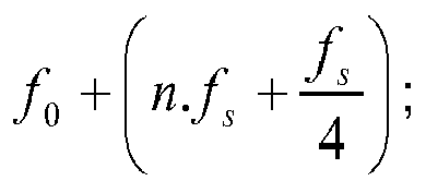
- the output of the up-converter 230 may be in accordance with the following equation: f 0 + n . f s + f s 4 .
- the up-converter 230 outputs substantially only the upper sideband at f 0 + n . f s + f s 4 , since the carrier at f 0 and the lower sideband at f 0 ⁇ n . f s + f s 4 are largely supressed.
- the analogue PCB 200 may further comprise an RF front end module 240 configured to receive a received signal from the receiver antenna 320 via a coaxial cable 302.
- the RF front end module 240 may be further configured to receive a receiver gain signal from the receiver gain controller 150 of the digital PCB 100.
- the received signal from the receiver antenna 320 as influenced by the receiver gain signal, may be output to a down-converter 250 of the analogue PCB 200.
- the down-converter 250 may be a passive double balanced mixer and may output a signal.
- the down-converter 250 may receive the f 0 ⁇ n . f s + f s 4 signal from the up-converter 230 and the output, f 0 , from the RF front end 240. By impressing the echo information f 0 on the up-converter output, a signal defined by n . f s + f s 4 may be restored by the down-converter 250.
- the analogue PCB 200 may further comprise a baseband amplifier 260 configured to amplify the signal output by the down-converter 250.
- the analogue PCB 200 may further comprise a digitiser 270 configured to convert the analogue signal output by the baseband amplifier 260 into a digital signal.
- the digitiser 270 may be clocked at f s . Accordingly, the output spectrum from the digitiser is translated to f s 4 through the mixing process of the sampling, which provides an output that is independent of the value of n .
- the resulting digital data stream comprises interleaved orthogonal components in the format I, -Q, -I, Q (wherein the I, Q terminology is the standard terminology for complex sampling).
- the DDS 220 may have limited amplitude resolution (for example, 10 bits). In most applications, limited amplitude resolution would result in low signal to noise level due to amplitude quantisation. (In the 10 bit example, the signal to noise level may be limited to - 65dB.) However, the synchronism and the relationship between clock signal f s used by both the DDS 220 and the digitiser 270 means that quantizing noise is eliminated. Referring to Figure 2 , it can be seen that, for a particular clock frequency and integer value for n , the elimination of the quantising noise would reduce the signal to noise level from the order of -65 dB to the order of -270 dB. However, by adopting the synchronised quantizing, the signal to noise level drops further to the order of -320 dB. This aptly demonstrates a significant advantage provided by the arrangement of the disclosure.
- the signal frequency needs to satisfy the specified operating window of the digitizer 270, and must be compatible with the filtering requirements that enable control of noise generated in active circuitry. It needs also to avoid flicker noise.
- the digital signal produced by the digitiser 270 may be output via the serial programmable interface 110 to onward processing functionality 140 of the digital PCB.
- serial programmable interface 110 to interface between the analogue PCB 200 and the digital PCB 100 means that a commonly available DSP micro-circuit can be used without the need to use a bespoke FPGA (field programmable gate array) for receiving the signal on the digital PCB 100.
- bespoke FPGA field programmable gate array
- the onward processing circuitry 140 of the digital PCB 100 may output an analogue or digital video signal that embodies a real time video representation of subsurface features as detected by the radar system 1.
- the onward processing circuitry 140 of the digital PCB 100 may be associated with global positioning satellite (GPS) technology or other geo-location functionality such that passes of the radar system over a wide area can be coupled with the geo-location data so as to generate a wide area radar derived map.
- GPS global positioning satellite
- One application of the radar system 1 is in the context of a machine work tool.
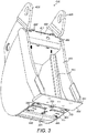
- FIG. 3 One embodiment of a machine work tool 400 comprising a radar system 1 of the present disclosure is shown in Figure 3 .
- the machine work tool 400 takes the form of an excavator bucket 400.
- the excavator bucket 400 may comprise a bucket cavity 410 for containing excavated material, attachment elements 420 for attachment of the excavator bucket 400 to an excavator (not shown), a bucket blade 430 comprising a front face 431 for cutting into a ground surface or other material to be excavated, and a bottom panel 440 that provides a surface of the excavator bucket 400 that sits adjacent the bucket blade 430.
- the bottom panel 440 may be above the bucket blade 430 when the excavator bucket 400 is in an orientation such that the bucket blade 430 is in a vertical orientation above a surface into which the bucket blade 430 is preparing to cut.
- the excavator bucket 400 may further comprise a top cavity 450, enclosed within the bucket cavity 410 at an opposing face of the bucket 400 relative to the bottom panel 440 and bucket blade 430.
- the top cavity 450 may comprise a removable panel 451 attached in position by fasteners 452, 453.
- the excavator bucket 400 may further comprise one or more conduits 460 within the bucket cavity providing a connection between the bottom panel 440 and the top cavity 450.
- the bottom panel 440 may comprise a recess 441 into which is mounted the antenna assembly 300 comprising the transmitter antenna 310 and the receiver antenna 320.
- the top cavity 450 may contain the radar control module 2 that comprises the digital PCB 100 and the analogue PCB 200.
- Coaxial cables 301, 302 facilitate communication between the antenna assembly 300 and the radar control module 2.
- the coaxial cables may be channelled in the conduits 460.
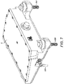
- a plurality of fasteners 305 may be employed to fasten the antenna assembly 300 into the recess 441 in the bottom panel 440 of the excavator bucket 400.
- the fasteners may be mounted such that they do not protrude beneath the surface of the bottom panel 440. In this way they are less vulnerable to damage.
- the fasteners may be mounted such that they do protrude above an inner surface of the bucket cavity 410. This is to enable the fasteners to be ground away (for example with an angle grinder) more easily in the event of a need to substitute the antenna assembly 300. While releasable fasteners may be employed, use of an excavator bucket for its intended purposes often means that fasteners may be bend or damaged, meaning that the most efficient method of removing the fasteners may be to grinding them away.
- each fasteners 305 comprises a bolt and a nut.
- the bolt comprises a head that is flush with the surface of the bottom panel 440.
- the nut sits inside the excavator bucket and protrudes above an interior surface of the bottom panel 440 of the bucket 400.
- the transmitter antenna 310 and receiver antenna 320 may be mounted to the antenna directionally such that they preferentially transmit in a direction towards the blade 430 and preferentially receive from a direction facing the blade 430.
- the signals that are sent to the transmitter antenna 310 and received from the receiver antenna 320 travel via the coaxial cables 301, 302 as discussed above in relation to Figure 1 .
- the signals sent via the coaxial cables 301, 302 are sent to and received from the radar control module 2 which is located within the top cavity 450 of the excavator bucket 400.
- the radar control module 2 Separating the radar control module 2 from the antenna assembly 300 means that only those components whose location relative to the cutting blade 430 is significant are located in that manner.
- those elements whose location relative to the cutting blade 430 is not significant, for example those of the radar control module 2 are located at a distance from the cutting blade 430. This means that they may be less vulnerable to damage from impact of the blade 430 and the bottom panel 440 impacting the ground or other materials to be excavated.
- the radar control module 2 may be fastened within the top cavity 450 using releasable fasteners 454.
- embodiments would include airborne vehicles, including autonomous aircraft such as drones. These embodiments may be particularly useful for applications where the aim of a subterranean profile is sought, perhaps in anticipation of construction work. Such embodiments may involve the obtaining of geo-location data to be matched with the radar system output information in order to build a subterranean map of the area that is subject to the radar system analysis.
- the radar system of the present disclosure is particularly appropriate for low cost applications, such as in machine work tools, where a whole range of tools may require the system and where the environment of the tool is such that component replacement may be more frequent that in other radar applications. Furthermore, the radar system of the disclosure is a low power solution by comparison with many prior art radar systems and, accordingly, it is appropriate for applications were low power is a particular benefit, such as in the context of small scale autonomous aircraft having small battery packs and where there is a desire for the radar system to have minimal impact on flying range.
- the radar system of the present disclosure is not limited to ground penetration applications.
- the radar system of the present disclosure is applicable to a wide variety of industrial applications such as those referenced above.
- the radar system of the disclosure may be appropriate for ground penetration applications.
- the radar system may be appropriate for use with machine work tools such that feedback may be provided to an operator in real time which allows immediate feedback prior to cutting into the ground. This enables subterranean features to be found and/or avoided as appropriate.
- the radar system may be appropriate for surveying applications. Surveying applications may involve mounting the radar system in an airborne vehicle or in a ground vehicle designed to complete a survey of a site perhaps by making a systematic pass (e.g. in rows or columns) across the site to be surveyed.
Landscapes
- Engineering & Computer Science (AREA)
- Radar, Positioning & Navigation (AREA)
- Remote Sensing (AREA)
- Physics & Mathematics (AREA)
- Computer Networks & Wireless Communication (AREA)
- General Physics & Mathematics (AREA)
- Electromagnetism (AREA)
- Mining & Mineral Resources (AREA)
- Civil Engineering (AREA)
- General Engineering & Computer Science (AREA)
- Structural Engineering (AREA)
- Microelectronics & Electronic Packaging (AREA)
- Power Engineering (AREA)
- Radar Systems Or Details Thereof (AREA)
Abstract
Description
- The disclosure relates to the field of radar systems, particularly for compact, close range applications. One application would be ground penetration radar in the context of a machine work tool such as an excavator bucket.
- Radar systems that detect the presence of objects in an environment are well known, including ground penetrating radar systems. The majority of such systems employ a pulsed radar technique, such that they transmit a train of short pulses (impulses) of electromagnetic energy with a high peak power (e.g. of the order of tens of kilowatts). The pulse energy is reflected by dielectric discontinuities such that the radar receives echoes in one to one correspondence with the transmitted pulses. This energy is reflected by dielectric discontinuities and received by the radar to produce a profile of the subsurface objects. This allows a profile of the reflecting objects to be produced. Since the time intervals involved are very short (typically sub-nanosecond), the sampling of the echoes must be stroboscopic. To obtain high resolutions, such systems require large instantaneous bandwidth and high peak power. This results in a wastage of energy since the interval of echo delay must be visited sequentially, whereas each transmission penetrates and excites echoes from the entire delay space.
- Stepped frequency radar systems overcome many of the issues just described in relation to impulse radar systems. In particular, the energy efficiency of a stepped radar frequency system is much higher than that of a pulsed radar system. However, stepped frequency radar systems tend not to be employed in small scale, low cost radar systems because of difficulties in implementation, generally resulting in higher cost.
- There are two approaches to stepped frequency radar systems, homodyne and heterodyne. Homodyne systems are simple to implement but require detection of signals at DC with competition against flicker noise and DC drift. Heterodyne systems require use of a sinusoidal carrier mixed to an intermediate frequency. This necessitates phase coherence between the transmitted and received signals which, in turn, requires a second receiver to sample the outgoing signal. This arrangement, however, introduces substantial complexity because of the need to match the two receivers accurately.
- Digital frequency generation (Direct Digital Synthesis (DDS)) is not capable of operating directly at the frequencies required for a ground penetrating radar and requires at least frequency doubling, which is costly.
- Against this background there is provided a radar system in accordance with claim 1.
- The use of a direct digital synthesiser to generate an intermediate frequency (I.F.) off-set frequency; an up-converter comprising a quadrature mixer, single-side mixer or complex mixer to add the off-set frequency to the transmitted frequency; and a down-converter in the receive path driven by the off-set frequency as a local oscillator, enables the received information to be transferred to the I.F. frequency. This in turn can be sampled synchronously in such a way as to provide a complex data stream carrying amplitude and phase information. In this way, there is no need for a second receiver to recover the transmitted phase since phase coherence is intrinsic to the scheme. Accordingly, the system is implementable with only a single transmit channel and a single receive channel.
- Furthermore, the radar system is implementable using a single analogue printed circuit board (PCB) and a single digital PCB. Moreover, the low bandwidth achieved using low frequency I.F. reduces the sampling frequency required in digitising so that the data transfer between the analogue and digital PCBs is achievable via the serial programmable interface (SPI) of the digital PCB. This has a beneficial impact on cost since the need for custom interface circuitry is removed.
- Accordingly, the radar system of the present disclosure is low power, low data bandwidth and low cost, while achieving a high measurement bandwidth at radio frequency (R.F.).
- An embodiment of the invention is now described with reference to the accompanying drawings, in which:
-
Figure 1 shows a schematic representation of a radar system in accordance with the disclosure; -
Figure 2 shows the signal to noise levels achievable using the radar system of the present disclosure; -
Figure 3 shows a machine including work tool, wherein the machine comprises a radar system in accordance with the present disclosure; -
Figure 4 shows the machine work tool ofFigure 3 ; -
Figure 5 shows the machine work tool ofFigures 3 and4 ; -
Figure 6 shows a radar control module of the radar system ofFigure 1 located in a top cavity of the machine work tool ofFigures 3 to 6 ; -
Figure 7 shows theradar control module 2 ofFigure 6 in isolation; -
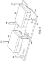
Figure 8 shows anantenna assembly 300 of the radar system ofFigure 1 ; and -
Figure 9 shows theantenna assembly 300 ofFigure 8 in isolation. - A radar system 1 in accordance with the present disclosure is shown in a highly schematic fashion in
Figure 1 . - The radar system 1 comprises an
antenna assembly 300 and aradar control module 2 comprising adigital PCB 100 and ananalogue PCB 200. - The antennal assembly may comprise a
transmitter antenna 310 and areceiver antenna 320. Thetransmitter antenna 310 may be configured to transmit electromagnetic radiation into the environment surrounding thetransmitter antenna 310. Thereceiver antenna 320 may be configured to receive electromagnetic radiation from the environment surrounding thereceiver antenna 320. Thetransmitter antenna 310 andreceiver antenna 320 may be highly directional and co-directed such that thereceiver antenna 320 is located so as to receive echoes of electromagnetic radiation emitted by thetransmitter antenna 310. - The
digital PCB 100 may be an off-the-shelf digital PCB comprising a serialprogrammable interface 110 by which data may be transferred onto and off thedigital PCB 100. - The
digital PCB 100 may comprise a masterclock signal generator 120 that provides a master clock signal, f, that governs the timings within the radar system 1. Thedigital PCB 100 may further comprise asampling frequency generator 130. The master clock signal f may be supplied to thesampling frequency generator 130 which uses the master clock signal f to calculate a sampling frequency
- In a specific embodiment, it may be that the master clock signal f = 10 MHz, integer m = 25 and the sampling frequency fs = 400 kHz.
- The
digital PCB 100 may further comprise anautomatic gain controller 140 configured to output a gain control signal. - The
digital PCB 100 may further comprise areceiver gain controller 150 and a processor 160 for processing data received, each of which are explained in more detail later. - The
analogue PCB 200 may comprise atransmission signal generator 210 configured to receive the master clock signal, f, from the master clock signal generator. The amplitude of the transmitted signal may be controlled via the serial programmable interface. The frequency may also be controlled via the serial programmable interface to be an integer p times the master clock frequency, f. Hence, thetransmission signal generator 210 may generate a transmission signal having a frequency f 0 = pf. The transmission signal may be output from theanalogue PCB 200 to thetransmitter antenna 310 via acoaxial cable 301. - The
analogue PCT 200 may further comprise a direct digital synthesiser (DDS) 220 configured to receive the sampling frequency signal
sampling frequency generator 130 and to use the sampling frequency signal to generate a synthesiser output signal which is a complex sinusoid synchronous to the master clock signal, f. The sinusoid uses in phase (I) and quadrature (Q) components that are mutually orthogonal. The synthesiser output signal may be defined by the following equation:
- The
analogue PCB 200 may further comprise an up-converter 230 configured to receive the transmission signal directly from thetransmission signal generator 210 and to receive the synthesiser output signal. The up-converter 230 may be configured to upward convert the transmission signal and the synthesiser output signal to produce an up-converter output. - The up-
converter 230 may be a complex mixer, a quadrature mixer or a single sideband mixer. The output of the up-converter 230 may be in accordance with the following equation:
- The up-
converter 230 outputs substantially only the upper sideband at

- The
analogue PCB 200 may further comprise an RFfront end module 240 configured to receive a received signal from thereceiver antenna 320 via acoaxial cable 302. The RFfront end module 240 may be further configured to receive a receiver gain signal from thereceiver gain controller 150 of thedigital PCB 100. The received signal from thereceiver antenna 320, as influenced by the receiver gain signal, may be output to a down-converter 250 of theanalogue PCB 200. The down-converter 250 may be a passive double balanced mixer and may output a signal. - The down-
converter 250 may receive the
converter 230 and the output, f 0, from the RFfront end 240. By impressing the echo information f 0 on the up-converter output, a signal defined by
converter 250. - The
analogue PCB 200 may further comprise abaseband amplifier 260 configured to amplify the signal output by the down-converter 250. - The
analogue PCB 200 may further comprise adigitiser 270 configured to convert the analogue signal output by thebaseband amplifier 260 into a digital signal. Thedigitiser 270 may be clocked at fs . Accordingly, the output spectrum from the digitiser is translated to
- Since the output of the
baseband amplifier 260 which is input to thedigitizer 270 remains in accordance with the equation
- The
DDS 220 may have limited amplitude resolution (for example, 10 bits). In most applications, limited amplitude resolution would result in low signal to noise level due to amplitude quantisation. (In the 10 bit example, the signal to noise level may be limited to - 65dB.) However, the synchronism and the relationship between clock signal fs used by both theDDS 220 and thedigitiser 270 means that quantizing noise is eliminated. Referring toFigure 2 , it can be seen that, for a particular clock frequency and integer value for n, the elimination of the quantising noise would reduce the signal to noise level from the order of -65 dB to the order of -270 dB. However, by adopting the synchronised quantizing, the signal to noise level drops further to the order of -320 dB. This aptly demonstrates a significant advantage provided by the arrangement of the disclosure. - As the skilled person understands, the signal frequency needs to satisfy the specified operating window of the
digitizer 270, and must be compatible with the filtering requirements that enable control of noise generated in active circuitry. It needs also to avoid flicker noise. - The digital signal produced by the
digitiser 270 may be output via the serialprogrammable interface 110 toonward processing functionality 140 of the digital PCB. - Use of the serial
programmable interface 110 to interface between theanalogue PCB 200 and thedigital PCB 100 means that a commonly available DSP micro-circuit can be used without the need to use a bespoke FPGA (field programmable gate array) for receiving the signal on thedigital PCB 100. - In one embodiment, the
onward processing circuitry 140 of thedigital PCB 100 may output an analogue or digital video signal that embodies a real time video representation of subsurface features as detected by the radar system 1. In another embodiment, theonward processing circuitry 140 of thedigital PCB 100 may be associated with global positioning satellite (GPS) technology or other geo-location functionality such that passes of the radar system over a wide area can be coupled with the geo-location data so as to generate a wide area radar derived map. - One application of the radar system 1 is in the context of a machine work tool.
- One embodiment of a
machine work tool 400 comprising a radar system 1 of the present disclosure is shown inFigure 3 . - In the illustrated embodiment, the
machine work tool 400 takes the form of anexcavator bucket 400. Theexcavator bucket 400 may comprise abucket cavity 410 for containing excavated material,attachment elements 420 for attachment of theexcavator bucket 400 to an excavator (not shown), abucket blade 430 comprising afront face 431 for cutting into a ground surface or other material to be excavated, and abottom panel 440 that provides a surface of theexcavator bucket 400 that sits adjacent thebucket blade 430. Thebottom panel 440 may be above thebucket blade 430 when theexcavator bucket 400 is in an orientation such that thebucket blade 430 is in a vertical orientation above a surface into which thebucket blade 430 is preparing to cut. - The
excavator bucket 400 may further comprise atop cavity 450, enclosed within thebucket cavity 410 at an opposing face of thebucket 400 relative to thebottom panel 440 andbucket blade 430. Thetop cavity 450 may comprise aremovable panel 451 attached in position byfasteners - The
excavator bucket 400 may further comprise one ormore conduits 460 within the bucket cavity providing a connection between thebottom panel 440 and thetop cavity 450. - The
bottom panel 440 may comprise arecess 441 into which is mounted theantenna assembly 300 comprising thetransmitter antenna 310 and thereceiver antenna 320. - The
top cavity 450 may contain theradar control module 2 that comprises thedigital PCB 100 and theanalogue PCB 200. -
Coaxial cables 301, 302 (seeFigure 1 ) facilitate communication between theantenna assembly 300 and theradar control module 2. The coaxial cables may be channelled in theconduits 460. - Referring to
Figure 4 , a plurality offasteners 305 may be employed to fasten theantenna assembly 300 into therecess 441 in thebottom panel 440 of theexcavator bucket 400. The fasteners may be mounted such that they do not protrude beneath the surface of thebottom panel 440. In this way they are less vulnerable to damage. By contrast, the fasteners may be mounted such that they do protrude above an inner surface of thebucket cavity 410. This is to enable the fasteners to be ground away (for example with an angle grinder) more easily in the event of a need to substitute theantenna assembly 300. While releasable fasteners may be employed, use of an excavator bucket for its intended purposes often means that fasteners may be bend or damaged, meaning that the most efficient method of removing the fasteners may be to grinding them away. - In the illustrated embodiment, each
fasteners 305 comprises a bolt and a nut. The bolt comprises a head that is flush with the surface of thebottom panel 440. The nut sits inside the excavator bucket and protrudes above an interior surface of thebottom panel 440 of thebucket 400. - The
transmitter antenna 310 andreceiver antenna 320 may be mounted to the antenna directionally such that they preferentially transmit in a direction towards theblade 430 and preferentially receive from a direction facing theblade 430. The signals that are sent to thetransmitter antenna 310 and received from thereceiver antenna 320 travel via thecoaxial cables Figure 1 . - Also as discussed above in relation to
Figure 1 , the signals sent via thecoaxial cables radar control module 2 which is located within thetop cavity 450 of theexcavator bucket 400. Separating theradar control module 2 from theantenna assembly 300 means that only those components whose location relative to thecutting blade 430 is significant are located in that manner. By contrast, those elements whose location relative to thecutting blade 430 is not significant, for example those of theradar control module 2, are located at a distance from thecutting blade 430. This means that they may be less vulnerable to damage from impact of theblade 430 and thebottom panel 440 impacting the ground or other materials to be excavated. - With reference to
Figures 5 and6 , theradar control module 2 may be fastened within thetop cavity 450 usingreleasable fasteners 454. - While the embodiment illustrated in
Figure 3 to 9 relates to anexcavator bucket 400, it should be noted that the claimed radar system is applicable to a much wider range of potential embodiments. For example, other embodiments would include other machine work tools such as breakers and drilling tools. - Looking outside the field of machines with work tools, other embodiments would include airborne vehicles, including autonomous aircraft such as drones. These embodiments may be particularly useful for applications where the aim of a subterranean profile is sought, perhaps in anticipation of construction work. Such embodiments may involve the obtaining of geo-location data to be matched with the radar system output information in order to build a subterranean map of the area that is subject to the radar system analysis.
- The radar system of the present disclosure is particularly appropriate for low cost applications, such as in machine work tools, where a whole range of tools may require the system and where the environment of the tool is such that component replacement may be more frequent that in other radar applications. Furthermore, the radar system of the disclosure is a low power solution by comparison with many prior art radar systems and, accordingly, it is appropriate for applications were low power is a particular benefit, such as in the context of small scale autonomous aircraft having small battery packs and where there is a desire for the radar system to have minimal impact on flying range.
- The radar system of the present disclosure is not limited to ground penetration applications.
- The radar system of the present disclosure is applicable to a wide variety of industrial applications such as those referenced above. In particular, the radar system of the disclosure may be appropriate for ground penetration applications. For example, the radar system may be appropriate for use with machine work tools such that feedback may be provided to an operator in real time which allows immediate feedback prior to cutting into the ground. This enables subterranean features to be found and/or avoided as appropriate. In another example, the radar system may be appropriate for surveying applications. Surveying applications may involve mounting the radar system in an airborne vehicle or in a ground vehicle designed to complete a survey of a site perhaps by making a systematic pass (e.g. in rows or columns) across the site to be surveyed.
Claims (14)
- A radar system configured for detecting profiles of objects within an environment, the radar system comprising:a master clock signal generator configured to generate a master clock signal having a frequency f;a sampling frequency generator configured to use the master clock signal to generate a sampling frequency output signal having a frequency
 a transmission signal generator configured to use the master clock signal to generate a transmission signal RFout for transmission at a frequency f 0 = pf where p is an integer;a direct digital synthesiser configured to receive the sampling frequency output signal to produce a synthesiser output signal defined by
 an up-converter comprising a quadrature mixer, single-side mixer or complex mixer configured to receive the transmission signal RFout and mix it with the synthesiser output signal to produce an up-converter output
 a down-converter comprising a passive double balanced mixer configured to mix the up-converter output
 a digitiser configured to receive the down-converter output and to sample the down-converter output at a frequency of fs to produce thereby a digitised output;a processor configured to receive the digitised output and provide it to radar data interpretation software for translating the output into an indication of profiles of objects in the environment.
 - The radar system of claim 1 further comprising:a first directional antenna configured to transmit the transmission signal RFout into the environment.
- The radar system of claim 1 or claim 2 further comprising:a second directional antenna configured to receive the received signal RFin corresponding to the transmission signal RFout as reflected by the environment.
- The radar system of any preceding claim further comprising a digital printed circuit board (PCB) and an analogue PCB, wherein:the digital PCB comprises some or all of:the master clock signal generator;the sampling frequency generator; andthe processor configured to receive the digitised output; andthe analogue PCB comprises some or all of:the transmission channel signal generator;the direct digital synthesiser;the up-converter;the down-converter; andthe digitiser.
- The radar system of claim 4 wherein the digital PCB comprises a serial programmable interface by which data is transferred between the digital PCB and the analogue PCB and between the analogue PCB and the digital PCB.
- The radar system of claim 4 or claim 5 wherein the digital PCB comprises an automatic gain controller configured to provide an automatic gain control signal to the transmission signal generator.
- The radar system of claim 6 when dependent upon claim 5 wherein the automatic gain control signal is output to the transmission signal generator via the serial programmable interface.
- The radar system of claim 4 or any claim dependent upon claim 4 wherein the digital PCB comprises an input gain controller configured to provide a gain control signal to the radio frequency receiver of the analogue PCB.
- The radar system of any preceding claim wherein the master clock signal frequency f is 10 MHz.
- The radar system of any preceding claim wherein the integer m is 25.
- The radar system of any preceding claim wherein the sampling frequency fs is 400 kHz.
- The radar system of any preceding claim wherein the integer n is one of the following: 0, 1, 2, 3, or 4.
- The radar system of any preceding claim wherein

- A work tool, such as a digging bucket, for a machine, the work tool comprising the radar system of any preceding claim.
Applications Claiming Priority (1)
| Application Number | Priority Date | Filing Date | Title |
|---|---|---|---|
| GB1717995.3A GB2570279A (en) | 2017-10-31 | 2017-10-31 | A radar system for detecting profiles of objects, particularly in a vicinity of a machine work tool |
Publications (2)
| Publication Number | Publication Date |
|---|---|
| EP3477330A1 true EP3477330A1 (en) | 2019-05-01 |
| EP3477330B1 EP3477330B1 (en) | 2022-02-16 |
Family
ID=60579977
Family Applications (1)
| Application Number | Title | Priority Date | Filing Date |
|---|---|---|---|
| EP18203225.0A Active EP3477330B1 (en) | 2017-10-31 | 2018-10-29 | A radar system for detecting profiles of objects, particularly in a vicinity of a machine work tool |
Country Status (3)
| Country | Link |
|---|---|
| US (1) | US11280881B2 (en) |
| EP (1) | EP3477330B1 (en) |
| GB (1) | GB2570279A (en) |
Cited By (1)
| Publication number | Priority date | Publication date | Assignee | Title |
|---|---|---|---|---|
| WO2023181022A1 (en) | 2022-03-21 | 2023-09-28 | Rodradar Ltd. | System and method for avoiding utility strikes by construction equipment |
Families Citing this family (2)
| Publication number | Priority date | Publication date | Assignee | Title |
|---|---|---|---|---|
| GB2586079A (en) * | 2019-08-02 | 2021-02-03 | Rodradar Ltd | A radar system for detecting profiles of objects, particularly in a vicinity of a machine work tool |
| CN111962602A (en) * | 2020-08-26 | 2020-11-20 | 徐州徐工挖掘机械有限公司 | Active anti-overbreak control system and method installed on excavator |
Citations (5)
| Publication number | Priority date | Publication date | Assignee | Title |
|---|---|---|---|---|
| US5003312A (en) * | 1986-03-28 | 1991-03-26 | Systron Donner Corporation | Velocity deception apparatus and method therefor |
| WO2001096901A2 (en) * | 2000-06-15 | 2001-12-20 | Honeywell International Inc. | Low probability of intercept coherent radar altimeter |
| EP2293097A2 (en) * | 2009-09-01 | 2011-03-09 | Robert Bosch GmbH | Method and device for providing a reflection signal |
| CN105093227A (en) * | 2015-08-27 | 2015-11-25 | 电子科技大学 | Traffic flow measuring apparatus and vehicle operation information obtaining method |
| EP3021178A1 (en) * | 2014-11-14 | 2016-05-18 | Caterpillar Inc. | System using radar apparatus for assisting a user of a machine of a kind comprising a body and an implement |
Family Cites Families (14)
| Publication number | Priority date | Publication date | Assignee | Title |
|---|---|---|---|---|
| GB2083977B (en) | 1980-08-26 | 1984-08-22 | Standard Telephones Cables Ltd | Single channel duplex radio system |
| GB2219899A (en) | 1988-06-17 | 1989-12-20 | Philips Electronic Associated | A zero if receiver |
| KR0139527B1 (en) | 1988-10-21 | 1998-07-01 | 아르레뜨 다낭제 | Transmitter, transmission method and receiver |
| GB9903461D0 (en) | 1999-02-17 | 1999-04-07 | Motherwell Control Systems Lim | Radar gauge |
| ATE326076T1 (en) | 2000-10-19 | 2006-06-15 | Norspace As | FREQUENCY CONVERTER |
| US6469661B1 (en) | 2001-01-19 | 2002-10-22 | Sandia Corporation | Correction of I/Q channel errors without calibration |
| US6700531B2 (en) * | 2002-07-17 | 2004-03-02 | Anritsu Company | Integrated multiple-up/down conversion radar test system |
| US20080074307A1 (en) | 2006-05-17 | 2008-03-27 | Olga Boric-Lubecke | Determining presence and/or physiological motion of one or more subjects within a doppler radar system |
| US7787533B2 (en) | 2007-01-03 | 2010-08-31 | Lockheed Martin Corporation | Alternative method for equalizing DDS generated waveforms |
| US7916083B2 (en) | 2008-05-01 | 2011-03-29 | Emag Technologies, Inc. | Vertically integrated electronically steered phased array and method for packaging |
| US20120154207A1 (en) * | 2010-12-21 | 2012-06-21 | Electronics And Telecommunications Research Institute | Apparatus and method for scanning image in image processing system |
| EP2825901A1 (en) * | 2012-03-12 | 2015-01-21 | Vermeer Manufacturing Co., Inc | Offset frequency homodyne ground penetrating radar |
| EP2822186B1 (en) | 2013-07-01 | 2015-09-23 | Nxp B.V. | A distributed radio system |
| US20160139259A1 (en) * | 2013-07-15 | 2016-05-19 | Northeastern University | Modular superheterodyne stepped frequency radar system for imaging |
-
2017
- 2017-10-31 GB GB1717995.3A patent/GB2570279A/en not_active Withdrawn
-
2018
- 2018-10-18 US US16/163,799 patent/US11280881B2/en active Active
- 2018-10-29 EP EP18203225.0A patent/EP3477330B1/en active Active
Patent Citations (5)
| Publication number | Priority date | Publication date | Assignee | Title |
|---|---|---|---|---|
| US5003312A (en) * | 1986-03-28 | 1991-03-26 | Systron Donner Corporation | Velocity deception apparatus and method therefor |
| WO2001096901A2 (en) * | 2000-06-15 | 2001-12-20 | Honeywell International Inc. | Low probability of intercept coherent radar altimeter |
| EP2293097A2 (en) * | 2009-09-01 | 2011-03-09 | Robert Bosch GmbH | Method and device for providing a reflection signal |
| EP3021178A1 (en) * | 2014-11-14 | 2016-05-18 | Caterpillar Inc. | System using radar apparatus for assisting a user of a machine of a kind comprising a body and an implement |
| CN105093227A (en) * | 2015-08-27 | 2015-11-25 | 电子科技大学 | Traffic flow measuring apparatus and vehicle operation information obtaining method |
Cited By (3)
| Publication number | Priority date | Publication date | Assignee | Title |
|---|---|---|---|---|
| WO2023181022A1 (en) | 2022-03-21 | 2023-09-28 | Rodradar Ltd. | System and method for avoiding utility strikes by construction equipment |
| EP4497019A4 (en) * | 2022-03-21 | 2025-07-09 | Rodradar Ltd | SYSTEM AND METHOD FOR PREVENTING SUPPLY SHOCKS IN CONSTRUCTION MACHINERY |
| US12455369B2 (en) | 2022-03-21 | 2025-10-28 | Rodradar Ltd. | System and method for avoiding utility strikes by construction equipment |
Also Published As
| Publication number | Publication date |
|---|---|
| GB201717995D0 (en) | 2017-12-13 |
| US11280881B2 (en) | 2022-03-22 |
| GB2570279A (en) | 2019-07-24 |
| US20190129001A1 (en) | 2019-05-02 |
| EP3477330B1 (en) | 2022-02-16 |
Similar Documents
| Publication | Publication Date | Title |
|---|---|---|
| US6445334B1 (en) | Ground penetrating radar system | |
| EP3477330B1 (en) | A radar system for detecting profiles of objects, particularly in a vicinity of a machine work tool | |
| CN104237877B (en) | Onboard automatic speed measuring and height measuring radar system and speed measuring and height measuring method | |
| EP1082621B1 (en) | System and method for distance measurement by inphase and quadrature signals in a radio system | |
| EP3531164A1 (en) | Phase synchronization method and device and storage medium | |
| EP3396406A1 (en) | Phase synchronization method, device thereof and equipment | |
| US8115666B2 (en) | Ground penetrating synthetic aperture radar | |
| US20110273324A1 (en) | Continuous high-accuracy locating method and apparatus | |
| US7710311B2 (en) | Short range radar small in size and low in power consumption and controlling method thereof | |
| US4125804A (en) | Mobile radar method for sensing inclusions in subsoil | |
| JPH06160515A (en) | Motion compensation method of synthetic aperture radar and position measurement method by radar | |
| US20090167589A1 (en) | Earth-penetrating radar with inherent near-field rejection | |
| RU2496120C2 (en) | Multifunctional multirange scalable radar system for aircraft | |
| Li et al. | Enhanced DME carrier phase: concepts, implementation, and flight‐test results | |
| EP2913690B1 (en) | Positioning system and method | |
| EP1631836B1 (en) | Methods and apparatus for simulating a doppler signal for self-testing an altimeter in stationary condition | |
| US20090315754A1 (en) | Method and radar system for coherent detection of moving objects | |
| CN106154264B (en) | Multi-band reconfigurable underground radar profiler system | |
| US20060197699A1 (en) | Active module integrated into an electronically scanned antenna, and radar comprising such an antenna, applied especially to meteorology | |
| CN103688189A (en) | Radar receiver | |
| RU2541886C2 (en) | System for electronic jamming of radio communication system | |
| US5955971A (en) | Window-passage detection system of an airplane | |
| RU2539334C1 (en) | System for electronic jamming of radio communication system | |
| CN214750849U (en) | High-precision GNSS base station | |
| CN116559878A (en) | A Ka-band VVD-SAR system |
Legal Events
| Date | Code | Title | Description |
|---|---|---|---|
| PUAI | Public reference made under article 153(3) epc to a published international application that has entered the european phase |
Free format text: ORIGINAL CODE: 0009012 |
|
| STAA | Information on the status of an ep patent application or granted ep patent |
Free format text: STATUS: THE APPLICATION HAS BEEN PUBLISHED |
|
| AK | Designated contracting states |
Kind code of ref document: A1 Designated state(s): AL AT BE BG CH CY CZ DE DK EE ES FI FR GB GR HR HU IE IS IT LI LT LU LV MC MK MT NL NO PL PT RO RS SE SI SK SM TR |
|
| AX | Request for extension of the european patent |
Extension state: BA ME |
|
| STAA | Information on the status of an ep patent application or granted ep patent |
Free format text: STATUS: REQUEST FOR EXAMINATION WAS MADE |
|
| 17P | Request for examination filed |
Effective date: 20191030 |
|
| RBV | Designated contracting states (corrected) |
Designated state(s): AL AT BE BG CH CY CZ DE DK EE ES FI FR GB GR HR HU IE IS IT LI LT LU LV MC MK MT NL NO PL PT RO RS SE SI SK SM TR |
|
| RAP1 | Party data changed (applicant data changed or rights of an application transferred) |
Owner name: RODRADAR LTD. |
|
| GRAP | Despatch of communication of intention to grant a patent |
Free format text: ORIGINAL CODE: EPIDOSNIGR1 |
|
| STAA | Information on the status of an ep patent application or granted ep patent |
Free format text: STATUS: GRANT OF PATENT IS INTENDED |
|
| RIC1 | Information provided on ipc code assigned before grant |
Ipc: G01S 7/288 20060101AFI20210531BHEP Ipc: G01S 7/282 20060101ALI20210531BHEP Ipc: E02F 9/26 20060101ALI20210531BHEP Ipc: G01S 13/10 20060101ALI20210531BHEP Ipc: G01S 13/88 20060101ALI20210531BHEP Ipc: E02F 3/40 20060101ALN20210531BHEP Ipc: G01S 13/86 20060101ALN20210531BHEP |
|
| INTG | Intention to grant announced |
Effective date: 20210625 |
|
| GRAJ | Information related to disapproval of communication of intention to grant by the applicant or resumption of examination proceedings by the epo deleted |
Free format text: ORIGINAL CODE: EPIDOSDIGR1 |
|
| STAA | Information on the status of an ep patent application or granted ep patent |
Free format text: STATUS: REQUEST FOR EXAMINATION WAS MADE |
|
| INTC | Intention to grant announced (deleted) | ||
| GRAS | Grant fee paid |
Free format text: ORIGINAL CODE: EPIDOSNIGR3 |
|
| STAA | Information on the status of an ep patent application or granted ep patent |
Free format text: STATUS: GRANT OF PATENT IS INTENDED |
|
| GRAP | Despatch of communication of intention to grant a patent |
Free format text: ORIGINAL CODE: EPIDOSNIGR1 |
|
| RIC1 | Information provided on ipc code assigned before grant |
Ipc: G01S 13/86 20060101ALN20211118BHEP Ipc: E02F 3/40 20060101ALN20211118BHEP Ipc: G01S 13/88 20060101ALI20211118BHEP Ipc: G01S 13/10 20060101ALI20211118BHEP Ipc: E02F 9/26 20060101ALI20211118BHEP Ipc: G01S 7/282 20060101ALI20211118BHEP Ipc: G01S 7/288 20060101AFI20211118BHEP |
|
| INTG | Intention to grant announced |
Effective date: 20211214 |
|
| GRAA | (expected) grant |
Free format text: ORIGINAL CODE: 0009210 |
|
| STAA | Information on the status of an ep patent application or granted ep patent |
Free format text: STATUS: THE PATENT HAS BEEN GRANTED |
|
| AK | Designated contracting states |
Kind code of ref document: B1 Designated state(s): AL AT BE BG CH CY CZ DE DK EE ES FI FR GB GR HR HU IE IS IT LI LT LU LV MC MK MT NL NO PL PT RO RS SE SI SK SM TR |
|
| REG | Reference to a national code |
Ref country code: GB Ref legal event code: FG4D |
|
| REG | Reference to a national code |
Ref country code: CH Ref legal event code: EP |
|
| REG | Reference to a national code |
Ref country code: DE Ref legal event code: R096 Ref document number: 602018030855 Country of ref document: DE |
|
| REG | Reference to a national code |
Ref country code: AT Ref legal event code: REF Ref document number: 1469221 Country of ref document: AT Kind code of ref document: T Effective date: 20220315 |
|
| REG | Reference to a national code |
Ref country code: IE Ref legal event code: FG4D |
|
| REG | Reference to a national code |
Ref country code: SE Ref legal event code: TRGR |
|
| REG | Reference to a national code |
Ref country code: LT Ref legal event code: MG9D |
|
| REG | Reference to a national code |
Ref country code: NL Ref legal event code: MP Effective date: 20220216 |
|
| REG | Reference to a national code |
Ref country code: AT Ref legal event code: MK05 Ref document number: 1469221 Country of ref document: AT Kind code of ref document: T Effective date: 20220216 |
|
| PG25 | Lapsed in a contracting state [announced via postgrant information from national office to epo] |
Ref country code: RS Free format text: LAPSE BECAUSE OF FAILURE TO SUBMIT A TRANSLATION OF THE DESCRIPTION OR TO PAY THE FEE WITHIN THE PRESCRIBED TIME-LIMIT Effective date: 20220216 Ref country code: PT Free format text: LAPSE BECAUSE OF FAILURE TO SUBMIT A TRANSLATION OF THE DESCRIPTION OR TO PAY THE FEE WITHIN THE PRESCRIBED TIME-LIMIT Effective date: 20220616 Ref country code: NO Free format text: LAPSE BECAUSE OF FAILURE TO SUBMIT A TRANSLATION OF THE DESCRIPTION OR TO PAY THE FEE WITHIN THE PRESCRIBED TIME-LIMIT Effective date: 20220516 Ref country code: NL Free format text: LAPSE BECAUSE OF FAILURE TO SUBMIT A TRANSLATION OF THE DESCRIPTION OR TO PAY THE FEE WITHIN THE PRESCRIBED TIME-LIMIT Effective date: 20220216 Ref country code: LT Free format text: LAPSE BECAUSE OF FAILURE TO SUBMIT A TRANSLATION OF THE DESCRIPTION OR TO PAY THE FEE WITHIN THE PRESCRIBED TIME-LIMIT Effective date: 20220216 Ref country code: HR Free format text: LAPSE BECAUSE OF FAILURE TO SUBMIT A TRANSLATION OF THE DESCRIPTION OR TO PAY THE FEE WITHIN THE PRESCRIBED TIME-LIMIT Effective date: 20220216 Ref country code: ES Free format text: LAPSE BECAUSE OF FAILURE TO SUBMIT A TRANSLATION OF THE DESCRIPTION OR TO PAY THE FEE WITHIN THE PRESCRIBED TIME-LIMIT Effective date: 20220216 Ref country code: BG Free format text: LAPSE BECAUSE OF FAILURE TO SUBMIT A TRANSLATION OF THE DESCRIPTION OR TO PAY THE FEE WITHIN THE PRESCRIBED TIME-LIMIT Effective date: 20220516 |
|
| PG25 | Lapsed in a contracting state [announced via postgrant information from national office to epo] |
Ref country code: PL Free format text: LAPSE BECAUSE OF FAILURE TO SUBMIT A TRANSLATION OF THE DESCRIPTION OR TO PAY THE FEE WITHIN THE PRESCRIBED TIME-LIMIT Effective date: 20220216 Ref country code: LV Free format text: LAPSE BECAUSE OF FAILURE TO SUBMIT A TRANSLATION OF THE DESCRIPTION OR TO PAY THE FEE WITHIN THE PRESCRIBED TIME-LIMIT Effective date: 20220216 Ref country code: GR Free format text: LAPSE BECAUSE OF FAILURE TO SUBMIT A TRANSLATION OF THE DESCRIPTION OR TO PAY THE FEE WITHIN THE PRESCRIBED TIME-LIMIT Effective date: 20220517 Ref country code: FI Free format text: LAPSE BECAUSE OF FAILURE TO SUBMIT A TRANSLATION OF THE DESCRIPTION OR TO PAY THE FEE WITHIN THE PRESCRIBED TIME-LIMIT Effective date: 20220216 Ref country code: AT Free format text: LAPSE BECAUSE OF FAILURE TO SUBMIT A TRANSLATION OF THE DESCRIPTION OR TO PAY THE FEE WITHIN THE PRESCRIBED TIME-LIMIT Effective date: 20220216 |
|
| PG25 | Lapsed in a contracting state [announced via postgrant information from national office to epo] |
Ref country code: IS Free format text: LAPSE BECAUSE OF FAILURE TO SUBMIT A TRANSLATION OF THE DESCRIPTION OR TO PAY THE FEE WITHIN THE PRESCRIBED TIME-LIMIT Effective date: 20220617 |
|
| PG25 | Lapsed in a contracting state [announced via postgrant information from national office to epo] |
Ref country code: SM Free format text: LAPSE BECAUSE OF FAILURE TO SUBMIT A TRANSLATION OF THE DESCRIPTION OR TO PAY THE FEE WITHIN THE PRESCRIBED TIME-LIMIT Effective date: 20220216 Ref country code: SK Free format text: LAPSE BECAUSE OF FAILURE TO SUBMIT A TRANSLATION OF THE DESCRIPTION OR TO PAY THE FEE WITHIN THE PRESCRIBED TIME-LIMIT Effective date: 20220216 Ref country code: RO Free format text: LAPSE BECAUSE OF FAILURE TO SUBMIT A TRANSLATION OF THE DESCRIPTION OR TO PAY THE FEE WITHIN THE PRESCRIBED TIME-LIMIT Effective date: 20220216 Ref country code: EE Free format text: LAPSE BECAUSE OF FAILURE TO SUBMIT A TRANSLATION OF THE DESCRIPTION OR TO PAY THE FEE WITHIN THE PRESCRIBED TIME-LIMIT Effective date: 20220216 Ref country code: DK Free format text: LAPSE BECAUSE OF FAILURE TO SUBMIT A TRANSLATION OF THE DESCRIPTION OR TO PAY THE FEE WITHIN THE PRESCRIBED TIME-LIMIT Effective date: 20220216 Ref country code: CZ Free format text: LAPSE BECAUSE OF FAILURE TO SUBMIT A TRANSLATION OF THE DESCRIPTION OR TO PAY THE FEE WITHIN THE PRESCRIBED TIME-LIMIT Effective date: 20220216 |
|
| REG | Reference to a national code |
Ref country code: DE Ref legal event code: R097 Ref document number: 602018030855 Country of ref document: DE |
|
| PG25 | Lapsed in a contracting state [announced via postgrant information from national office to epo] |
Ref country code: AL Free format text: LAPSE BECAUSE OF FAILURE TO SUBMIT A TRANSLATION OF THE DESCRIPTION OR TO PAY THE FEE WITHIN THE PRESCRIBED TIME-LIMIT Effective date: 20220216 |
|
| PLBE | No opposition filed within time limit |
Free format text: ORIGINAL CODE: 0009261 |
|
| STAA | Information on the status of an ep patent application or granted ep patent |
Free format text: STATUS: NO OPPOSITION FILED WITHIN TIME LIMIT |
|
| 26N | No opposition filed |
Effective date: 20221117 |
|
| PG25 | Lapsed in a contracting state [announced via postgrant information from national office to epo] |
Ref country code: SI Free format text: LAPSE BECAUSE OF FAILURE TO SUBMIT A TRANSLATION OF THE DESCRIPTION OR TO PAY THE FEE WITHIN THE PRESCRIBED TIME-LIMIT Effective date: 20220216 |
|
| PG25 | Lapsed in a contracting state [announced via postgrant information from national office to epo] |
Ref country code: MC Free format text: LAPSE BECAUSE OF FAILURE TO SUBMIT A TRANSLATION OF THE DESCRIPTION OR TO PAY THE FEE WITHIN THE PRESCRIBED TIME-LIMIT Effective date: 20220216 |
|
| REG | Reference to a national code |
Ref country code: CH Ref legal event code: PL |
|
| REG | Reference to a national code |
Ref country code: BE Ref legal event code: MM Effective date: 20221031 |
|
| PG25 | Lapsed in a contracting state [announced via postgrant information from national office to epo] |
Ref country code: LU Free format text: LAPSE BECAUSE OF NON-PAYMENT OF DUE FEES Effective date: 20221029 |
|
| PG25 | Lapsed in a contracting state [announced via postgrant information from national office to epo] |
Ref country code: LI Free format text: LAPSE BECAUSE OF NON-PAYMENT OF DUE FEES Effective date: 20221031 Ref country code: CH Free format text: LAPSE BECAUSE OF NON-PAYMENT OF DUE FEES Effective date: 20221031 |
|
| PG25 | Lapsed in a contracting state [announced via postgrant information from national office to epo] |
Ref country code: BE Free format text: LAPSE BECAUSE OF NON-PAYMENT OF DUE FEES Effective date: 20221031 |
|
| PG25 | Lapsed in a contracting state [announced via postgrant information from national office to epo] |
Ref country code: IE Free format text: LAPSE BECAUSE OF NON-PAYMENT OF DUE FEES Effective date: 20221029 |
|
| PG25 | Lapsed in a contracting state [announced via postgrant information from national office to epo] |
Ref country code: HU Free format text: LAPSE BECAUSE OF FAILURE TO SUBMIT A TRANSLATION OF THE DESCRIPTION OR TO PAY THE FEE WITHIN THE PRESCRIBED TIME-LIMIT; INVALID AB INITIO Effective date: 20181029 |
|
| PG25 | Lapsed in a contracting state [announced via postgrant information from national office to epo] |
Ref country code: CY Free format text: LAPSE BECAUSE OF FAILURE TO SUBMIT A TRANSLATION OF THE DESCRIPTION OR TO PAY THE FEE WITHIN THE PRESCRIBED TIME-LIMIT Effective date: 20220216 |
|
| PG25 | Lapsed in a contracting state [announced via postgrant information from national office to epo] |
Ref country code: MK Free format text: LAPSE BECAUSE OF FAILURE TO SUBMIT A TRANSLATION OF THE DESCRIPTION OR TO PAY THE FEE WITHIN THE PRESCRIBED TIME-LIMIT Effective date: 20220216 |
|
| PG25 | Lapsed in a contracting state [announced via postgrant information from national office to epo] |
Ref country code: TR Free format text: LAPSE BECAUSE OF FAILURE TO SUBMIT A TRANSLATION OF THE DESCRIPTION OR TO PAY THE FEE WITHIN THE PRESCRIBED TIME-LIMIT Effective date: 20220216 |
|
| PG25 | Lapsed in a contracting state [announced via postgrant information from national office to epo] |
Ref country code: MT Free format text: LAPSE BECAUSE OF FAILURE TO SUBMIT A TRANSLATION OF THE DESCRIPTION OR TO PAY THE FEE WITHIN THE PRESCRIBED TIME-LIMIT Effective date: 20220216 |
|
| PGFP | Annual fee paid to national office [announced via postgrant information from national office to epo] |
Ref country code: DE Payment date: 20251022 Year of fee payment: 8 |
|
| PGFP | Annual fee paid to national office [announced via postgrant information from national office to epo] |
Ref country code: GB Payment date: 20251015 Year of fee payment: 8 |
|
| PGFP | Annual fee paid to national office [announced via postgrant information from national office to epo] |
Ref country code: IT Payment date: 20251021 Year of fee payment: 8 |
|
| PGFP | Annual fee paid to national office [announced via postgrant information from national office to epo] |
Ref country code: FR Payment date: 20251018 Year of fee payment: 8 |
|
| PGFP | Annual fee paid to national office [announced via postgrant information from national office to epo] |
Ref country code: SE Payment date: 20251011 Year of fee payment: 8 |