EP3477277A2 - Apparatus and method for increasing dynamic range of a particle sensor - Google Patents
Apparatus and method for increasing dynamic range of a particle sensor Download PDFInfo
- Publication number
- EP3477277A2 EP3477277A2 EP18198519.3A EP18198519A EP3477277A2 EP 3477277 A2 EP3477277 A2 EP 3477277A2 EP 18198519 A EP18198519 A EP 18198519A EP 3477277 A2 EP3477277 A2 EP 3477277A2
- Authority
- EP
- European Patent Office
- Prior art keywords
- receiver
- transmitter
- view
- pair
- particle
- Prior art date
- Legal status (The legal status is an assumption and is not a legal conclusion. Google has not performed a legal analysis and makes no representation as to the accuracy of the status listed.)
- Withdrawn
Links
- 239000002245 particle Substances 0.000 title claims abstract description 154
- 238000000034 method Methods 0.000 title claims description 18
- 238000001514 detection method Methods 0.000 claims abstract description 74
- 230000003287 optical effect Effects 0.000 claims description 58
- 230000010287 polarization Effects 0.000 description 21
- 238000010586 diagram Methods 0.000 description 18
- 230000035945 sensitivity Effects 0.000 description 10
- 238000012512 characterization method Methods 0.000 description 6
- 238000012545 processing Methods 0.000 description 6
- XLYOFNOQVPJJNP-UHFFFAOYSA-N water Substances O XLYOFNOQVPJJNP-UHFFFAOYSA-N 0.000 description 6
- 230000003197 catalytic effect Effects 0.000 description 1
- 238000013461 design Methods 0.000 description 1
- 230000003467 diminishing effect Effects 0.000 description 1
- 239000012530 fluid Substances 0.000 description 1
- 238000005259 measurement Methods 0.000 description 1
- 238000012544 monitoring process Methods 0.000 description 1
- 230000000644 propagated effect Effects 0.000 description 1
- 238000012163 sequencing technique Methods 0.000 description 1
- 239000000779 smoke Substances 0.000 description 1
- 238000001228 spectrum Methods 0.000 description 1
Images


Classifications
-
- G—PHYSICS
- G01—MEASURING; TESTING
- G01N—INVESTIGATING OR ANALYSING MATERIALS BY DETERMINING THEIR CHEMICAL OR PHYSICAL PROPERTIES
- G01N21/00—Investigating or analysing materials by the use of optical means, i.e. using sub-millimetre waves, infrared, visible or ultraviolet light
- G01N21/84—Systems specially adapted for particular applications
- G01N21/88—Investigating the presence of flaws or contamination
- G01N21/94—Investigating contamination, e.g. dust
-
- G—PHYSICS
- G01—MEASURING; TESTING
- G01N—INVESTIGATING OR ANALYSING MATERIALS BY DETERMINING THEIR CHEMICAL OR PHYSICAL PROPERTIES
- G01N15/00—Investigating characteristics of particles; Investigating permeability, pore-volume, or surface-area of porous materials
- G01N15/10—Investigating individual particles
- G01N15/14—Electro-optical investigation, e.g. flow cytometers
- G01N15/1456—Electro-optical investigation, e.g. flow cytometers without spatial resolution of the texture or inner structure of the particle, e.g. processing of pulse signals
-
- G—PHYSICS
- G01—MEASURING; TESTING
- G01J—MEASUREMENT OF INTENSITY, VELOCITY, SPECTRAL CONTENT, POLARISATION, PHASE OR PULSE CHARACTERISTICS OF INFRARED, VISIBLE OR ULTRAVIOLET LIGHT; COLORIMETRY; RADIATION PYROMETRY
- G01J1/00—Photometry, e.g. photographic exposure meter
- G01J1/02—Details
- G01J1/04—Optical or mechanical part supplementary adjustable parts
- G01J1/0407—Optical elements not provided otherwise, e.g. manifolds, windows, holograms, gratings
- G01J1/0462—Slit arrangements
-
- G—PHYSICS
- G01—MEASURING; TESTING
- G01N—INVESTIGATING OR ANALYSING MATERIALS BY DETERMINING THEIR CHEMICAL OR PHYSICAL PROPERTIES
- G01N15/00—Investigating characteristics of particles; Investigating permeability, pore-volume, or surface-area of porous materials
- G01N15/02—Investigating particle size or size distribution
- G01N15/0205—Investigating particle size or size distribution by optical means, e.g. by light scattering, diffraction, holography or imaging
- G01N15/0211—Investigating a scatter or diffraction pattern
-
- G—PHYSICS
- G01—MEASURING; TESTING
- G01N—INVESTIGATING OR ANALYSING MATERIALS BY DETERMINING THEIR CHEMICAL OR PHYSICAL PROPERTIES
- G01N15/00—Investigating characteristics of particles; Investigating permeability, pore-volume, or surface-area of porous materials
- G01N15/06—Investigating concentration of particle suspensions
-
- G—PHYSICS
- G01—MEASURING; TESTING
- G01N—INVESTIGATING OR ANALYSING MATERIALS BY DETERMINING THEIR CHEMICAL OR PHYSICAL PROPERTIES
- G01N21/00—Investigating or analysing materials by the use of optical means, i.e. using sub-millimetre waves, infrared, visible or ultraviolet light
- G01N21/17—Systems in which incident light is modified in accordance with the properties of the material investigated
- G01N21/47—Scattering, i.e. diffuse reflection
-
- G01N15/075—
-
- G—PHYSICS
- G01—MEASURING; TESTING
- G01N—INVESTIGATING OR ANALYSING MATERIALS BY DETERMINING THEIR CHEMICAL OR PHYSICAL PROPERTIES
- G01N15/00—Investigating characteristics of particles; Investigating permeability, pore-volume, or surface-area of porous materials
- G01N15/10—Investigating individual particles
- G01N15/14—Electro-optical investigation, e.g. flow cytometers
- G01N15/1434—Electro-optical investigation, e.g. flow cytometers using an analyser being characterised by its optical arrangement
-
- G—PHYSICS
- G01—MEASURING; TESTING
- G01N—INVESTIGATING OR ANALYSING MATERIALS BY DETERMINING THEIR CHEMICAL OR PHYSICAL PROPERTIES
- G01N15/00—Investigating characteristics of particles; Investigating permeability, pore-volume, or surface-area of porous materials
- G01N2015/0042—Investigating dispersion of solids
- G01N2015/0046—Investigating dispersion of solids in gas, e.g. smoke
-
- G—PHYSICS
- G01—MEASURING; TESTING
- G01N—INVESTIGATING OR ANALYSING MATERIALS BY DETERMINING THEIR CHEMICAL OR PHYSICAL PROPERTIES
- G01N15/00—Investigating characteristics of particles; Investigating permeability, pore-volume, or surface-area of porous materials
- G01N15/02—Investigating particle size or size distribution
- G01N2015/0294—Particle shape
-
- G—PHYSICS
- G01—MEASURING; TESTING
- G01N—INVESTIGATING OR ANALYSING MATERIALS BY DETERMINING THEIR CHEMICAL OR PHYSICAL PROPERTIES
- G01N15/00—Investigating characteristics of particles; Investigating permeability, pore-volume, or surface-area of porous materials
- G01N15/10—Investigating individual particles
- G01N15/14—Electro-optical investigation, e.g. flow cytometers
- G01N15/1434—Electro-optical investigation, e.g. flow cytometers using an analyser being characterised by its optical arrangement
- G01N2015/1447—Spatial selection
-
- G—PHYSICS
- G01—MEASURING; TESTING
- G01N—INVESTIGATING OR ANALYSING MATERIALS BY DETERMINING THEIR CHEMICAL OR PHYSICAL PROPERTIES
- G01N21/00—Investigating or analysing materials by the use of optical means, i.e. using sub-millimetre waves, infrared, visible or ultraviolet light
- G01N21/84—Systems specially adapted for particular applications
- G01N21/88—Investigating the presence of flaws or contamination
- G01N21/94—Investigating contamination, e.g. dust
- G01N2021/945—Liquid or solid deposits of macroscopic size on surfaces, e.g. drops, films, or clustered contaminants
-
- H—ELECTRICITY
- H04—ELECTRIC COMMUNICATION TECHNIQUE
- H04B—TRANSMISSION
- H04B10/00—Transmission systems employing electromagnetic waves other than radio-waves, e.g. infrared, visible or ultraviolet light, or employing corpuscular radiation, e.g. quantum communication
- H04B10/11—Arrangements specific to free-space transmission, i.e. transmission through air or vacuum
Definitions
- Particles such as volcanic ash and supercooled water droplets can detrimentally affect aircraft performance. These particles typically have mean volumetric diameters (MVDs) of about fifty microns.
- the supercooled water droplets form ice when contacting, e . g . an airfoil, of an aircraft. Icing of airfoils has caused aircraft catastrophes. Many modern aircraft are designed to include ice protected surfaces and fly in conditions of icing arising from supercooled water droplets of fifty microns or less.
- a particle detection system comprises at least one transmitter; at least one receiver; a first interrogation volume formed by a first intersection of a first pair of a transmitter beam of a transmitter and a receiver field of view of a receiver; and a second interrogation volume formed by a second intersection of a second pair of a transmitter beam of a transmitter and a receiver field of view of a receiver.
- another particle detection system comprises a transmitter; a receiver; an interrogation volume formed by an intersection of a transmitter beam of the transmitter and the receiver field of view of a receiver; and t least one amplifier system, coupled to the receiver, configured to output at least two signals each of which has been amplified by different gain levels.
- the illustrated embodiments may be used in vehicles for particle detection.
- the volume may be located in undisturbed space, e . g . undisturbed from the fluid flow (such as airflow) around the vehicle.
- the illustrated embodiments can be used for other applications such as monitoring particulates in exhaust of smoke stacks, and in catalytic reactors.
- the invention uses two or more interrogation volumes to increase dynamic range and maintain a broad range of sensitivity.
- An interrogation volume is a volume in which particles are characterized.
- two detector dynamic ranges can be used. Both embodiments will be subsequently described.
- One interrogation volume is relatively small, and in which particles having a relatively small mean volumetric diameter (MVD) (or a smaller MVD) are characterized.
- the other interrogation volume is relatively large, and in which particles having a relatively large MVD (or a larger MVD) are characterized.
- interrogation volumes can be used. If more than two interrogation volumes are used, then then the volume of each additional region is, e.g., correspondingly scaled between the size of the interrogation volumes used to characterize immediately smaller and immediately large particles.
- Smaller interrogation volumes are used to characterized smaller particles because the intensity of optical energy radiated from an optical source, e.g. a LASER, can be higher in the smaller volume, particularly for example if the electromagnetic energy is focused. More light energy is scattered by the smaller particles and received by an optical receiver, and thus sensitivity is maintained across the detection spectrum of small to large particles.
- the optical energy received by a receiver can be used to characterize the particles, e . g . size and shape. Larger volumes are necessary to accurately perform such characterizations of larger particles.
- the foregoing systems can be used to characterize particles having MVDs ranging from three to one thousand microns, one to five thousand microns, or even broader ranges.
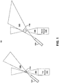
- Figure 1 illustrates a block diagram of one embodiment of a system comprising two pairs of transmitters and receivers (first system) 100.
- the transmitters described herein are optical transmitters such as LASERs
- the receivers described herein are optical receivers.
- the optical transmitters and receivers operate at single frequencies or over a narrow bandwidth, e . g ., to improve receiver signal to noise ratio.
- the subsequently illustrated transmitters are exemplified having focused optical beams, and the subsequently illustrated receivers are exemplified has having fields of view with focal points.
- the transmitters can have divergent or collimated optical beams; receivers can have fields of view that are divergent or collimated.
- the transmitter beam and the receiver field of view occur in free space.
- the first system 100 comprises a first transmitter 102A, a second transmitter 102B, a first receiver 104A, and a second receiver 104B.
- the first transmitter 102A has a first transmitter beam 106A which is focused.
- the second transmitter 102B has a second transmitter beam 106B which is focused.
- the first receiver 104A has a first receiver field of view 108A which is focused.
- the second receiver 104B has a second receiver field of view 108B which is focused.
- the focal length of each beam is adjusted to create interrogation volumes of different sizes.
- the first transmitter beam 106A and the first receiver field of view 108A overlap, or intersect, creating a first interrogation volume 110A.
- the second transmitter beam 106B and the second receiver field of view 108B overlap, or intersect, creating a second interrogation volume 110B.
- the volume of the second interrogation volume 110B is greater than the volume of the first interrogation volume 110A; alternatively, as will be subsequently be illustrated the volumes of the first interrogation volume 110A and the second interrogation volume 110B can be designed so that the former is larger than the latter.
- the first interrogation volume 110A and the second interrogation volume 110B are proximate to one another so that the characterization of small and large particles is made in about the same region.
- Light is scattered by particles having relatively small MVDs in the first interrogation volume 110A back along the first receiver field of view 108A to the first receiver 104A.
- Light is scattered by particles having relatively large MVDs in the second interrogation volume 110B back along the second receiver field of view 108B to the second receiver 104B.
- parameters of transmitter and receiver components such as lens parameters, slit parameters, and detectors (e . g . amplifier gain) may vary depending upon corresponding volume of an interrogation volume and a size of particles being detected in such interrogation volume.
- An exemplary receiver will now be described.
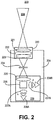
- Figure 2 illustrates a block diagram of one embodiment of a receiver (first receiver) 200.
- the receiver field of view 208, an optical beam, of the first receiver 200 is also illustrated; the receiver field of view 208 corresponds to light scattered by particles in an interrogation volume formed, in part, by the receiver field of view 208.
- the illustrated optical receiver includes collection optics 220, a first slit 224, and a first optical detection system 229.
- the collection optics 220 defines and collects light through the receiver field of view 208 for processing by the rest of the first receiver 200.
- the collection optics 220 includes a collection lens 221, a solar filter 222, and/or a first focusing lens 223.
- the collection optics 220 includes one or more mirrors that direct the optical beam 208 so that the optical receiver 208 need not be in line with the optical beam 208.
- the collection optics 220 can include one or more of the aforementioned components, and/or other components.
- collection optics 220 including a collection lens 221, a solar filter 222, and a first focusing lens 223, will now be described.
- the collection lens 221 collimates received light from the optical beam 208; the collimated light propagates to the solar filter 222.
- the solar filter 222 filters out all light except for the optical wavelengths emitted by transmitter(s), e . g . of the systems described herein; the solar filter 222 improves the signal to noise ratio of the receiver.
- the first focusing lens focuses the collimated, filtered light (propagated through the solar filter 222) on to the first slit 224.
- the first slit 224 is designed to remove a portion of scattered light from the edge of the optical beam 208 so that scattered light from the most uniform part of the optical beam 208 is detected; this enhances measurement accuracy.
- the slit 224 may also be used to define the length and height of a corresponding interrogation volume.
- the filtered light after passing through the first slit 224, impinges the first optical detection system 229.
- the first receiver 200 detects the presence of particles of a particular MVD, or range of MVDs, in a corresponding interrogation volume when the first optical detection system 229 detects the presence of light.
- the first optical detection system 229 determines the intensity and/or polarization of such light. The intensity and/or polarization respectively correspond to, and can be subsequently processed to determine, the number of such particles, and the shape of such particles.
- the first optical detection system 229 comprises a collimating lens 225, a polarizing beam splitter, a second focusing lens 227A, a first optical, or S, detector 228B, a third focusing lens 227B, and a second optical, or P, detector 228B.
- the collimating lens 224 collimates the light that passes through the first slit 224 and impinges upon the collimating lens 225.
- the polarizing beam splitter 226 separates linear polarized light so that light which is substantially parallel with the light emitted by the transmitter(s) (p polarization) is directed along path p, and light which is substantially perpendicular with the light emitted by the transmitter(s) (s polarization) is directed along path s. If the detected light scattered by particles substantially has p polarization then the particles are substantially spherical in shape. The intensity of light scattered with s polarization (relative to the intensity of light scattered with p polarization) indicates the degree to which the particles (which scatters the light) are aspherical.
- the second focusing lens 227A focuses collimated light of a first (s) polarization in the s path onto the S detector 228A.
- the third focusing lens 227B focuses collimated light of a second (p) polarization in the p path onto the P detector 228B.
- Each of the S detector 228A and the P detector 228B comprise a photodetector and signal processing electronics (such as filters, amplifiers, and/or analog to digital converters).
- the photodetectors may be any type of photodetectors, including photoelectric or photovoltaic detectors.
- One example of a photoelectric detector that may be used is an avalanche photodiode.
- detector(s), e.g. the S detector 228A and the P detector 228B, used to detect smaller particles have greater sensitivities then the corresponding detectors used to detect larger particles.
- the first optical detection system 229 can be implemented differently.
- the first optical detection system 229 can be implemented using the components illustrated in Figure 2 , but excluding the polarizing beam splitter 226, the second focusing lens 227B, and the P detector 228B.
- the S detector 228A will detect scattered light of all polarizations, including S and P polarizations. This embodiment can be used to determine the amount, but not the shape, of particles in a corresponding interrogation volume.
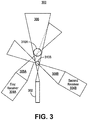
- Figure 3 illustrates a block diagram of one embodiment of a system comprising one transmitter and two receivers (second system) 300.
- the second system 300 includes a transmitter 302, a first receiver 304A, and a second receiver 304B.
- the transmitter 302 has a transmitter beam 306 which is focused.
- the first receiver 304A has a first receiver field of view 308A which is focused.
- the second receiver 304B has a second receiver field of view 308B which is focused.
- the transmitter beam 306 and the first receiver field of view 108A overlap, or intersect, creating a first interrogation volume 310A.
- the transmitter beam 306 and the second receiver field of view 308B overlap, or intersect, creating a second interrogation volume 310B.
- the volume of the second interrogation volume 310B is smaller than the volume of the first interrogation volume 310A.
- the first interrogation volume 310A and the second interrogation volume 310B are proximate to one another so that the characterization of large and small particles is made in about the same region.
- Light is scattered by particles having relatively large MVDs in the first interrogation volume 310A back along the first receiver field of view 308A to the first receiver 304A.
- Light is scattered by particles having relatively small MVDs in the second interrogation volume 310B back along the second receiver field of view 308B to the second receiver 304B.
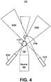
- FIG. 4 illustrates a block diagram of one embodiment of a system comprising two transmitters and one receiver (third system) 400.
- the third system 400 includes a first transmitter 402A, a second transmitter 402B, and a receiver 404.
- the first transmitter 402A has a first transmitter beam 406A which is focused.
- the second transmitter 402B has a second transmitter beam 406B which is focused.
- the receiver 404 has a receiver field of view 408 which is focused.
- the first transmitter beam 406A and the receiver field of view 408 overlap, or intersect, creating a first interrogation volume 410A.
- the second transmitter beam 406B and the receiver field of view 408 overlap, or intersect, creating a second interrogation volume 410B.
- the volume of the second interrogation volume 410B is smaller than the volume of the first interrogation volume 410A.
- the first interrogation volume 410A and the second interrogation volume 410B are proximate to one another so that the characterization of large particles and small particles is made in about the same region.
- Light is scattered by particles having relatively large MVDs in the first interrogation volume 410A back along the receiver field of view 408 to the receiver 404.
- Light is scattered by particles having relatively small MVDs in the second interrogation volume 410B back along the receiver field of view 408 to the receiver 404.
- the receiver 404 discriminates between scattering from the first interrogation volume 410A and the second interrogation volume 410B because the first transmitter 402A and the second transmitter 402B transmit light of different wavelengths.
- Figure 5 illustrates one embodiment of a receiver configured to receive optical signals of two different wavelengths, e . g . 905nm and 1550, (dichromatic receiver or second receiver) 500.
- the illustrated dichromatic receiver 500 comprises collection optics 520, a dichromatic beam splitter 543, a first receiver system 540A, and a second receiver system 540B.
- the receiver field of view 408 impinges the collection optics 520.
- the collection optics 520 includes a lens and a solar filter, and projects collimated light upon a dichromatic beam splitter 543.
- the lens facilitates the receiver field of view 408 to be focused.
- the collection optics 520 includes one or more mirrors that direct the receiver field of view 408 so that the receiver 408 need not be in line with the receiver field of view 408.
- the dichromatic beam splitter 543 directs light of different wavelengths in different directions, for example to the first receiver system 540A and the second receiver system 540B.
- the first receiver system 540A processes and detects light of a first wavelength (or a first narrow band of wavelengths).
- the first receiver system 540A comprises a fourth focusing lens 544A, a second slit 523A, and a second optical detection system 529A.
- the fourth focusing lens 544A, the second slit 523A, and the first optical detection system 529A function in an analogous manner as described above for the first focusing lens 223, the first slit 224, and the first optical detection system 229.
- the second receiver system 540B processes and detects light of a second wavelength (or a second narrow band of wavelengths).
- the second receiver system 540B comprises a fifth focusing lens 544B, a third slit 523B, and a third optical detection system 529B.
- the fifth focusing lens 544B, the third slit 523B, and the second optical detection system 529B function in an analogous manner as described above for the first focusing lens 223, the first slit 224, and the first optical detection system 229.
- Figure 6 illustrates a block diagram of one embodiment of a system comprising one transmitter and one receiver (fourth system) 600.
- the fourth system 600 includes a transmitter 602 and a receiver 604.
- the transmitter 602 has a first transmitter beam 606 which is focused.
- the receiver 604 has a first receiver field of view 608A and a second receiver field of view 608B both of which are focused.
- the first receiver field of view 608A and the second receiver field of view 608B may occur simultaneously or sequentially as will be further described below.
- the transmitter beam 606 and the first receiver field of view 608A overlap, or intersect, creating a first interrogation volume 610A.
- the transmitter beam 606 and the second receiver field of view 608B overlap, or intersect, creating a second interrogation volume 610B.
- the volume of the first interrogation volume 610A is smaller than the volume of the second interrogation volume 610B.
- the first interrogation volume 610A and the second interrogation volume 610B are proximate to one another so that the characterization of small and large particles is made in about the same region.
- Light is scattered by particles having relatively small MVDs in the first interrogation volume 610A back along the first receiver field of view 608A to the receiver 604.
- Light is scattered by particles having relatively large MVDs in the second interrogation volume 610B back along the second receiver field of view 608B to the receiver 604.
- the first receiver field of view 608A and the second receiver field of view 608B occur sequentially at different times. In another embodiment, the more than two receiver field of views may occur, e.g. in a specific order, at different times.
- the sequencing of the receiver field of views may be accomplished by moving the receiver 604 or component(s) of the receiver 604 with an electric motor and/or a piezoelectric motor.
- the whole collection lens 221 or just mirrors (described above) in the collection lens 221 may be periodically moved.
- the receiver 604 can be moved between more than two positions to create more than more than two receiver field of views, and thus, interrogation volumes.
- electro-optical devices such as an electro-optical modulator, can be used to sequence the receiver field of views using electrical control, e . g . voltage, signals.
- the time that a receiver field of view occurs varies based upon environment. In upper atmospheric conditions where fewer large particles exist, the second receiver field of view 608B will occur for a significantly longer time, e . g . ninety percent of a time period, whereas the first receiver field of view 608A would occur for a shorter time, e.g. ten percent of the time period. In environments where there is an equal distribution of large and small particles, then the duty cycle (corresponding to time of occurrence for the first receiver field of view 608B and the second receiver field of view 608B) may be fifty percent.
- the receiver 604 has a first receiver field of view 608A and a second receiver field of view 608B which are occur simultaneously.
- Figure 7 illustrates a block diagram of one embodiment of a receiver having two simultaneous receiver field of views (third receiver) 700.
- the illustrated third receiver 700 comprises collection optics 720, a fourth slit 723A, a fifth slit 723B, a first receiver system 740A, and a second receiver system 740B.
- the fourth slit 723A and the fifth slit 723B are offset from the centerline of the collection optics 720.
- the second receiver field of view 608B and the first receiver field of view 608A are also correspondingly projected at such angles from the centerline.
- the second receiver field of view 608B impinges upon the collection optics 720, and is focused upon the fourth slit 723A.
- the collection optics 720 includes the same components which are described as being included in the collection optics 220 of Figure 2 .
- the fourth slit 723A which performs the same function as described above for the first slit 223A, projects - at the same angle as the second receiver field of view 608B is projected through the collection optics 720 - the second receiver field of view 608B onto a fourth optical detection system 729A.
- the fourth optical detection system 729A processes the second receiver field of view 608B in a manner similar as described above for the first optical detection system 229 of Figure 2 .
- the first receiver field of view 608A impinges upon the collection optics 720, and is focused upon the fifth slit 723B.
- the fifth slit 723B which performs the same function as described above for the first slit 223A, projects - at the same angle as the first receiver field of view 608A is projected through the collection optics 720 - the first receiver field of view 608A onto a fifth optical detection system 729B.
- the fifth optical detection system 729B processes the first receiver field of view 608A in a manner similar as described above for the first optical detection system 229 of Figure 2 .
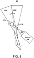
- FIG. 8 illustrates a block diagram of another embodiment of a system comprising one transmitter and one receiver (fifth system) 800.
- the fifth system 800 comprises a transmitter 802 and a receiver 804.
- the transmitter 802, or component(s) thereof are moved between at least two positions so that at least a first transmitter beam 806A and a second transmitter beam 806B occur and are sequenced.
- the receiver 804 has a receiver field of view 808.
- the transmitter 802, or component(s) thereof are moved by periodically moving the transmitter 802 or component(s) of the transmitter 802 with an electric motor and/or a piezoelectric motor.
- an electric motor and/or a piezoelectric motor For example, lens(es) and/ mirror(s) in the transmitter 802 may be periodically moved.
- electro-optical devices such as an electro-optical modulator, can be used to sequence the transmitter beams using electrical control, e . g . voltage, signals.
- the first transmitter beam 806A and the receiver field of view 808A overlap, or intersect, creating a first interrogation volume 810A.
- the second transmitter beam 806A and the receiver field of view 808 overlap, or intersect, creating a second interrogation volume 810B.
- the volume of the first interrogation volume 810A is larger than the volume of the second interrogation volume 810B.
- the first interrogation volume 810A and the second interrogation volume 810B are proximate to one another so that the characterization of small and large particles is made in about the same region.
- Light is scattered by particles having relatively large MVDs in the first interrogation volume 810A back along the receiver field of view 808 to the receiver 804.
- Light is scattered by particles having relatively small MVDs in the second interrogation volume 810B back along the receiver field of view 808 to the receiver 804.
- the time that a transmitter beam occurs varies based upon environment. In upper atmospheric conditions where fewer large particles exist, the first transmitter beam 806A will be used for a significantly longer period, e . g . consuming ninety percent of a time period, than the second transmitter beam 806B, e . g . consuming ten percent of the time period. In environments where there is an equal distribution of large and small particles, then the duty cycle would be, e . g ., fifty percent. In one embodiment, the transmitter beam can be moved between more than two positions to create more than more than two interrogation volumes.
- Figure 9 illustrates one embodiment for increasing dynamic range of a particle sensor while maintaining broad range of sensitivity 900.
- the embodiment of method 900 shown in Figure 9 is described herein as being implemented in the systems shown in Figures 1 through 8 , and 10 , it is to be understood that other embodiments can be implemented in other ways.
- the blocks of the flow diagrams have been arranged in a generally sequential manner for ease of explanation; however, it is to be understood that this arrangement is merely exemplary, and it should be recognized that the processing associated with the methods (and the blocks shown in the Figure) can occur in a different order (for example, where at least some of the processing associated with the blocks is performed in parallel and/or in an event-driven manner).
- detecting the presence of the first particle of the first particle size in the first interrogation volume comprises detecting during a first time period. In another embodiment, detecting the presence of the first particle of the first particle size in the first interrogation volume comprises detecting at least one of (a) intensity of the scattered light and (b) relative polarization of the scattered light.
- detecting the presence of the second particle of the second particle size in the second interrogation volume comprises detecting during a second time period subsequent to the first time period. In another embodiment, the first time period and the second time period sequentially repeat. In a further embodiment, the duty cycle is smaller for the time period corresponding to an interrogation volume used to detect larger particles. In yet another embodiment, detecting the presence of the second particle of the second particle size in the second interrogation volume comprises detecting at least one of (a) intensity of scattered light and (b) relative polarization of the scattered light. In yet a further embodiment, blocks 990 and 992 are performed by at least one transmitter, e.g. a LASER, and at least one receiver, e.g. an optical receiver.
- FIG. 10 illustrates a block diagram of another embodiment of a system comprising one transmitter and one receiver (sixth system) 1000.
- the sixth system 1000 comprises a transmitter 1002 and a receiver 1004 respectively having a transmitter beam 1006 and a receiver field of view 1008.
- the transmitter 1002 is implemented as described above, and has a fixed position.
- the receiver 1004 is implemented as described above with respect to Figure 2 .
- the transmitter beam 1006 and the receiver field of view 1008 overlap, or intersect, creating an interrogation volume 1010.
- the interrogation volume 1010 is used to characterize both small and large particles, and is sized accordingly.
- Light is scattered by particles having relatively large MVDs in the interrogation volume 1010 back along the receiver field of view 1008 to the receiver 1004.
- Light is also scattered by particles having relatively small MVDs in the interrogation volume 1010 back along the receiver field of view 1008 to the receiver 804.
- the output of the receiver 1004, e.g. an output of an optical detection system, is coupled to one or more amplifier systems.
- an S amplifier system 1012A and a P amplifier system 1012B are coupled to the output of the receiver 1004, e.g. respectively to the outputs of an S detector 228A and a P detector 228B.
- the S amplifier system 1012A has at least one output, e.g. a first output 1016A-1 and a second output 1016A-2.
- the P amplifier system 1012B has at least one output, e.g. a first output 1016BA-1 and a second output 1016B-2.
- each amplifier system may only have a single output. Further, if only a single detector is used, as described above, then only one amplifier system is coupled to the output of the receiver 1004.
- the first amplifier system 1010 has a first output 1016A-1 and a second output 1016B-1.
- the second output 1016B-1 has a higher dynamic range than the first output 1016A-1.
- the difference in dynamic range occurs because the signals at the first output 1016A-1 and the second output 1016B-1 are substantially identical versions of a signal from the output of the receiver 1004 except that the signal at the first output 1016A-1 has been amplified less than the signal at the second output 1016B-1.
- the amplifier system 1010 comprises at least two series coupled amplifier, e.g. a first amplifier 1014A and a second amplifier 1014B.
- the first output 1016A-1 is coupled to the output of an amplifier, e . g . the first amplifier 1014A, preceding one or more other amplifiers in the amplifier system 1010.
- the second output 1016B-1 is coupled to the output of an amplifier, e . g . the second amplifier 1014B, succeeding one or more other amplifiers in the amplifier system 1010.
- the gain associated with the preceding amplifiers is lower than the gain associated with the preceding and succeeding amplifiers.
- Outputs having relatively lower gains, e.g. the first output 1016A-1 are used to amplify signals corresponding to relatively larger particles.
- Outputs have relatively higher gains, e.g. the second output 1016A-2 are used to amplify signals corresponding to relatively smaller particles.
- Each of the amplifier systems 1012A, 1012B illustrated in Figure 10 may alternatively be implemented by at least one variable gain amplifier (VGA) whose gain may be varied over time.
- VGA variable gain amplifier
- an amplifier system 1012A with a variable gain amplifier can have a single output that generates signals amplified by two or more gain levels and which correspond to different particle sizes as described above.
- the duty cycle of such gains may be as described above with respect to Figure 3 .
- Figure 11 illustrates another embodiment for increasing dynamic range of a particle sensor while maintaining broad range of sensitivity 1100.
- method 1100 shown in Figure 1 is described herein as being implemented in the systems shown in Figures 1 through 8 , and 10 , it is to be understood that other embodiments can be implemented in other ways.
- the blocks of the flow diagrams have been arranged in a generally sequential manner for ease of explanation; however, it is to be understood that this arrangement is merely exemplary, and it should be recognized that the processing associated with the methods (and the blocks shown in the Figure) can occur in a different order (for example, where at least some of the processing associated with the blocks is performed in parallel and/or in an event-driven manner).
- detecting the presence of the first particle of the first particle size in the first interrogation volume comprises detecting during a first time period. In another embodiment, detecting the presence of the first particle of the first particle size in the first interrogation volume comprises detecting at least one of (a) intensity of scattered light and (b) relative polarization of scattered light.
- detecting the presence of the second particle of the second particle size in the first interrogation volume comprises detecting during a second time period subsequent to the first time period. In another embodiment, the first time period and the second time period sequentially repeat. In a further embodiment, the duty cycle is smaller for the for the time period corresponding to an interrogation volume used to detect larger particles. In yet another embodiment, detecting the presence of the second particle of the second particle size in the first interrogation volume comprises detecting at least one of (a) intensity of scattered light and (b) relative polarization of the scattered light. In yet a further embodiment, blocks 990 and 992 are performed by at least one transmitter, e.g. a LASER, and at least one receiver, e.g. an optical receiver.
Abstract
Description
- Particles such as volcanic ash and supercooled water droplets can detrimentally affect aircraft performance. These particles typically have mean volumetric diameters (MVDs) of about fifty microns.
- The supercooled water droplets form ice when contacting, e.g. an airfoil, of an aircraft. Icing of airfoils has caused aircraft catastrophes. Many modern aircraft are designed to include ice protected surfaces and fly in conditions of icing arising from supercooled water droplets of fifty microns or less.
- There exist supercooled large water droplets having MVDs up to five thousand microns. Aircraft are not typically designed to fly in conditions of icing arising from supercooled large water droplets because such larger droplets (a) adhere to more of the aircraft surface than smaller droplets and (b) are more likely to move behind ice protected surfaces.
- Because aircraft are not protected from supercooled large water droplets, it is important for an aircraft to detect their presence so that the aircraft and/or its pilot can take action to avoid resulting icing. Modern particle sensors using optical transceiver systems are not typically designed to detect the presence of particles having MVDs with a dynamic range of one thousand while maintaining adequate detection sensitivity over the particle size range. Typical high dynamic range particle detection systems unsatisfactorily sacrifice detection sensitivity, e.g. for relatively small sized particles, to increase particle size detection dynamic range. For example, this can result in an undesirable tradeoff - facilitating detection of large particles while diminishing the detection accuracy of small particles, such as volcanic ash - which could lead to aircraft engine damage or even failure. Therefore, there is a need for a particle detector that has both high dynamic range of particle detection size, while maintaining adequate detection sensitivity over the particle size range.
- In one embodiment, a particle detection system is provided. The particle detection system comprises at least one transmitter; at least one receiver; a first interrogation volume formed by a first intersection of a first pair of a transmitter beam of a transmitter and a receiver field of view of a receiver; and a second interrogation volume formed by a second intersection of a second pair of a transmitter beam of a transmitter and a receiver field of view of a receiver.
- In another embodiment, another particle detection system is provided. The other particle detection system comprises a transmitter; a receiver; an interrogation volume formed by an intersection of a transmitter beam of the transmitter and the receiver field of view of a receiver; and t least one amplifier system, coupled to the receiver, configured to output at least two signals each of which has been amplified by different gain levels.
- Understanding that the drawings depict only exemplary embodiments and are not therefore to be considered limiting in scope, the exemplary embodiments will be described with additional specificity and detail through the use of the accompanying drawings, in which:
-
Figure 1 illustrates a block diagram of one embodiment of a system comprising two pairs of transmitters and receivers; -
Figure 2 illustrates a block diagram of one embodiment of a receiver; -
Figure 3 illustrates a block diagram of one embodiment of a system comprising one transmitter and two receivers; -
Figure 4 illustrates a block diagram of one embodiment of a system comprising two transmitters and one receiver; -
Figure 5 illustrates one embodiment of a receiver configured to receive optical signals of two different wavelengths; -
Figure 6 illustrates a block diagram of one embodiment of a system comprising one transmitter and one receiver; -
Figure 7 illustrates a block diagram of one embodiment of a receiver having two simultaneous receiver field of views; -
Figure 8 illustrates a block diagram of another embodiment of a system comprising one transmitter and one receiver; -
Figure 9 illustrates one embodiment for increasing dynamic range of a particle sensor while maintaining broad range of sensitivity; -
Figure 10 illustrates a block diagram of another embodiment of a system comprising one transmitter and one receiver; and -
Figure 11 illustrates another embodiment for increasing dynamic range of a particle sensor while maintaining broad range of sensitivity. - In accordance with common practice, the various described features are not drawn to scale but are drawn to emphasize specific features relevant to the exemplary embodiments. Reference characters denote like elements throughout figures and text.
- In the following detailed description, reference is made to the accompanying drawings that form a part hereof, and in which is shown by way of illustration specific illustrative embodiments. However, it is to be understood that other embodiments may be utilized and that structural, mechanical, and electrical changes may be made. Furthermore, the method presented in the drawing figures and the specification is not to be construed as limiting the order in which the individual steps may be performed. The following detailed description is, therefore, not to be taken in a limiting sense.
- The illustrated embodiments may be used in vehicles for particle detection. For some vehicles, such as aircraft, the volume may be located in undisturbed space, e.g. undisturbed from the fluid flow (such as airflow) around the vehicle. Alternatively, the illustrated embodiments can be used for other applications such as monitoring particulates in exhaust of smoke stacks, and in catalytic reactors.
- In one embodiment, the invention uses two or more interrogation volumes to increase dynamic range and maintain a broad range of sensitivity. An interrogation volume is a volume in which particles are characterized. In another embodiment, two detector dynamic ranges can be used. Both embodiments will be subsequently described.
- For pedagogical reasons, for the embodiment with at least two interrogation volumes, two interrogation volumes will be subsequently described. One interrogation volume is relatively small, and in which particles having a relatively small mean volumetric diameter (MVD) (or a smaller MVD) are characterized. The other interrogation volume is relatively large, and in which particles having a relatively large MVD (or a larger MVD) are characterized.
- However, more than two interrogation volumes can be used. If more than two interrogation volumes are used, then then the volume of each additional region is, e.g., correspondingly scaled between the size of the interrogation volumes used to characterize immediately smaller and immediately large particles.
- Smaller interrogation volumes are used to characterized smaller particles because the intensity of optical energy radiated from an optical source, e.g. a LASER, can be higher in the smaller volume, particularly for example if the electromagnetic energy is focused. More light energy is scattered by the smaller particles and received by an optical receiver, and thus sensitivity is maintained across the detection spectrum of small to large particles. The optical energy received by a receiver can be used to characterize the particles, e.g. size and shape. Larger volumes are necessary to accurately perform such characterizations of larger particles. The foregoing systems can be used to characterize particles having MVDs ranging from three to one thousand microns, one to five thousand microns, or even broader ranges.
- Different techniques for characterizing particles in two or more interrogation volumes will now be described.
Figure 1 illustrates a block diagram of one embodiment of a system comprising two pairs of transmitters and receivers (first system) 100. For pedagogical reasons, the transmitters described herein are optical transmitters such as LASERs, and the receivers described herein are optical receivers. In another embodiment, the optical transmitters and receivers operate at single frequencies or over a narrow bandwidth, e.g., to improve receiver signal to noise ratio. - For pedagogical reasons, the subsequently illustrated transmitters are exemplified having focused optical beams, and the subsequently illustrated receivers are exemplified has having fields of view with focal points. Alternatively, the transmitters can have divergent or collimated optical beams; receivers can have fields of view that are divergent or collimated. In another embodiment, the transmitter beam and the receiver field of view occur in free space.
- The
first system 100 comprises afirst transmitter 102A, asecond transmitter 102B, a first receiver 104A, and asecond receiver 104B. Thefirst transmitter 102A has afirst transmitter beam 106A which is focused. Thesecond transmitter 102B has asecond transmitter beam 106B which is focused. The first receiver 104A has a first receiver field ofview 108A which is focused. Thesecond receiver 104B has a second receiver field ofview 108B which is focused. As exemplified for all illustrated systems, the focal length of each beam is adjusted to create interrogation volumes of different sizes. - The
first transmitter beam 106A and the first receiver field ofview 108A overlap, or intersect, creating afirst interrogation volume 110A. Thesecond transmitter beam 106B and the second receiver field ofview 108B overlap, or intersect, creating asecond interrogation volume 110B. The volume of thesecond interrogation volume 110B is greater than the volume of thefirst interrogation volume 110A; alternatively, as will be subsequently be illustrated the volumes of thefirst interrogation volume 110A and thesecond interrogation volume 110B can be designed so that the former is larger than the latter. In one embodiment, thefirst interrogation volume 110A and thesecond interrogation volume 110B are proximate to one another so that the characterization of small and large particles is made in about the same region. - Light is scattered by particles having relatively small MVDs in the
first interrogation volume 110A back along the first receiver field ofview 108A to the first receiver 104A. Light is scattered by particles having relatively large MVDs in thesecond interrogation volume 110B back along the second receiver field ofview 108B to thesecond receiver 104B. - For the systems illustrated herein, parameters of transmitter and receiver components such as lens parameters, slit parameters, and detectors (e.g. amplifier gain) may vary depending upon corresponding volume of an interrogation volume and a size of particles being detected in such interrogation volume. An exemplary receiver will now be described.
-
Figure 2 illustrates a block diagram of one embodiment of a receiver (first receiver) 200. The receiver field ofview 208, an optical beam, of thefirst receiver 200 is also illustrated; the receiver field ofview 208 corresponds to light scattered by particles in an interrogation volume formed, in part, by the receiver field ofview 208. The illustrated optical receiver includescollection optics 220, afirst slit 224, and a firstoptical detection system 229. - The
collection optics 220 defines and collects light through the receiver field ofview 208 for processing by the rest of thefirst receiver 200. In one embodiment, thecollection optics 220 includes acollection lens 221, asolar filter 222, and/or a first focusinglens 223. In another embodiment, thecollection optics 220 includes one or more mirrors that direct theoptical beam 208 so that theoptical receiver 208 need not be in line with theoptical beam 208. For purposes of clarity, thecollection optics 220 can include one or more of the aforementioned components, and/or other components. - The operation of one embodiment of
collection optics 220, including acollection lens 221, asolar filter 222, and a first focusinglens 223, will now be described. Thecollection lens 221 collimates received light from theoptical beam 208; the collimated light propagates to thesolar filter 222. - The
solar filter 222 filters out all light except for the optical wavelengths emitted by transmitter(s), e.g. of the systems described herein; thesolar filter 222 improves the signal to noise ratio of the receiver. The first focusing lens focuses the collimated, filtered light (propagated through the solar filter 222) on to thefirst slit 224. Thefirst slit 224 is designed to remove a portion of scattered light from the edge of theoptical beam 208 so that scattered light from the most uniform part of theoptical beam 208 is detected; this enhances measurement accuracy. Theslit 224 may also be used to define the length and height of a corresponding interrogation volume. - The filtered light, after passing through the
first slit 224, impinges the firstoptical detection system 229. In one embodiment, thefirst receiver 200 detects the presence of particles of a particular MVD, or range of MVDs, in a corresponding interrogation volume when the firstoptical detection system 229 detects the presence of light. In another embodiment, the firstoptical detection system 229 determines the intensity and/or polarization of such light. The intensity and/or polarization respectively correspond to, and can be subsequently processed to determine, the number of such particles, and the shape of such particles. - In one embodiment, the first
optical detection system 229 comprises acollimating lens 225, a polarizing beam splitter, a second focusinglens 227A, a first optical, or S,detector 228B, a third focusinglens 227B, and a second optical, or P,detector 228B. Thecollimating lens 224 collimates the light that passes through thefirst slit 224 and impinges upon thecollimating lens 225. - The
polarizing beam splitter 226 separates linear polarized light so that light which is substantially parallel with the light emitted by the transmitter(s) (p polarization) is directed along path p, and light which is substantially perpendicular with the light emitted by the transmitter(s) (s polarization) is directed along path s. If the detected light scattered by particles substantially has p polarization then the particles are substantially spherical in shape. The intensity of light scattered with s polarization (relative to the intensity of light scattered with p polarization) indicates the degree to which the particles (which scatters the light) are aspherical. - The second focusing
lens 227A focuses collimated light of a first (s) polarization in the s path onto theS detector 228A. The third focusinglens 227B focuses collimated light of a second (p) polarization in the p path onto theP detector 228B. Each of theS detector 228A and theP detector 228B comprise a photodetector and signal processing electronics (such as filters, amplifiers, and/or analog to digital converters). The photodetectors may be any type of photodetectors, including photoelectric or photovoltaic detectors. One example of a photoelectric detector that may be used is an avalanche photodiode. In one embodiment, detector(s), e.g. theS detector 228A and theP detector 228B, used to detect smaller particles have greater sensitivities then the corresponding detectors used to detect larger particles. - The first
optical detection system 229 can be implemented differently. In an alternative embodiment, the firstoptical detection system 229 can be implemented using the components illustrated inFigure 2 , but excluding thepolarizing beam splitter 226, the second focusinglens 227B, and theP detector 228B. As a result, theS detector 228A will detect scattered light of all polarizations, including S and P polarizations. This embodiment can be used to determine the amount, but not the shape, of particles in a corresponding interrogation volume. -
Figure 3 illustrates a block diagram of one embodiment of a system comprising one transmitter and two receivers (second system) 300. Thesecond system 300 includes atransmitter 302, afirst receiver 304A, and a second receiver 304B. Thetransmitter 302 has atransmitter beam 306 which is focused. Thefirst receiver 304A has a first receiver field ofview 308A which is focused. The second receiver 304B has a second receiver field ofview 308B which is focused. - The
transmitter beam 306 and the first receiver field ofview 108A overlap, or intersect, creating afirst interrogation volume 310A. Thetransmitter beam 306 and the second receiver field ofview 308B overlap, or intersect, creating asecond interrogation volume 310B. The volume of thesecond interrogation volume 310B is smaller than the volume of thefirst interrogation volume 310A. In one embodiment, thefirst interrogation volume 310A and thesecond interrogation volume 310B are proximate to one another so that the characterization of large and small particles is made in about the same region. - Light is scattered by particles having relatively large MVDs in the
first interrogation volume 310A back along the first receiver field ofview 308A to thefirst receiver 304A. Light is scattered by particles having relatively small MVDs in thesecond interrogation volume 310B back along the second receiver field ofview 308B to the second receiver 304B. -
Figure 4 illustrates a block diagram of one embodiment of a system comprising two transmitters and one receiver (third system) 400. Thethird system 400 includes afirst transmitter 402A, asecond transmitter 402B, and areceiver 404. Thefirst transmitter 402A has afirst transmitter beam 406A which is focused. Thesecond transmitter 402B has asecond transmitter beam 406B which is focused. Thereceiver 404 has a receiver field ofview 408 which is focused. - The
first transmitter beam 406A and the receiver field ofview 408 overlap, or intersect, creating afirst interrogation volume 410A. Thesecond transmitter beam 406B and the receiver field ofview 408 overlap, or intersect, creating asecond interrogation volume 410B. The volume of thesecond interrogation volume 410B is smaller than the volume of thefirst interrogation volume 410A. In one embodiment, thefirst interrogation volume 410A and thesecond interrogation volume 410B are proximate to one another so that the characterization of large particles and small particles is made in about the same region. - Light is scattered by particles having relatively large MVDs in the
first interrogation volume 410A back along the receiver field ofview 408 to thereceiver 404. Light is scattered by particles having relatively small MVDs in thesecond interrogation volume 410B back along the receiver field ofview 408 to thereceiver 404. - In one embodiment, the
receiver 404 discriminates between scattering from thefirst interrogation volume 410A and thesecond interrogation volume 410B because thefirst transmitter 402A and thesecond transmitter 402B transmit light of different wavelengths.Figure 5 illustrates one embodiment of a receiver configured to receive optical signals of two different wavelengths, e.g. 905nm and 1550, (dichromatic receiver or second receiver) 500. - The illustrated
dichromatic receiver 500 comprisescollection optics 520, adichromatic beam splitter 543, afirst receiver system 540A, and asecond receiver system 540B. The receiver field ofview 408 impinges thecollection optics 520. In one embodiment, thecollection optics 520 includes a lens and a solar filter, and projects collimated light upon adichromatic beam splitter 543. The lens facilitates the receiver field ofview 408 to be focused. In another embodiment, thecollection optics 520 includes one or more mirrors that direct the receiver field ofview 408 so that thereceiver 408 need not be in line with the receiver field ofview 408. - The
dichromatic beam splitter 543, e.g. a dichromatic prism, directs light of different wavelengths in different directions, for example to thefirst receiver system 540A and thesecond receiver system 540B. Thefirst receiver system 540A processes and detects light of a first wavelength (or a first narrow band of wavelengths). Thefirst receiver system 540A comprises a fourth focusinglens 544A, asecond slit 523A, and a secondoptical detection system 529A. The fourth focusinglens 544A, thesecond slit 523A, and the firstoptical detection system 529A function in an analogous manner as described above for the first focusinglens 223, thefirst slit 224, and the firstoptical detection system 229. - The
second receiver system 540B processes and detects light of a second wavelength (or a second narrow band of wavelengths). Thesecond receiver system 540B comprises a fifth focusinglens 544B, athird slit 523B, and a thirdoptical detection system 529B. The fifth focusinglens 544B, thethird slit 523B, and the secondoptical detection system 529B function in an analogous manner as described above for the first focusinglens 223, thefirst slit 224, and the firstoptical detection system 229. -
Figure 6 illustrates a block diagram of one embodiment of a system comprising one transmitter and one receiver (fourth system) 600. Thefourth system 600 includes atransmitter 602 and areceiver 604. Thetransmitter 602 has afirst transmitter beam 606 which is focused. Thereceiver 604 has a first receiver field ofview 608A and a second receiver field ofview 608B both of which are focused. The first receiver field ofview 608A and the second receiver field ofview 608B may occur simultaneously or sequentially as will be further described below. - The
transmitter beam 606 and the first receiver field ofview 608A overlap, or intersect, creating afirst interrogation volume 610A. Thetransmitter beam 606 and the second receiver field ofview 608B overlap, or intersect, creating asecond interrogation volume 610B. The volume of thefirst interrogation volume 610A is smaller than the volume of thesecond interrogation volume 610B. In one embodiment, thefirst interrogation volume 610A and thesecond interrogation volume 610B are proximate to one another so that the characterization of small and large particles is made in about the same region. - Light is scattered by particles having relatively small MVDs in the
first interrogation volume 610A back along the first receiver field ofview 608A to thereceiver 604. Light is scattered by particles having relatively large MVDs in thesecond interrogation volume 610B back along the second receiver field ofview 608B to thereceiver 604. - In one embodiment, the first receiver field of
view 608A and the second receiver field ofview 608B occur sequentially at different times. In another embodiment, the more than two receiver field of views may occur, e.g. in a specific order, at different times. - The sequencing of the receiver field of views may be accomplished by moving the
receiver 604 or component(s) of thereceiver 604 with an electric motor and/or a piezoelectric motor. For example, thewhole collection lens 221 or just mirrors (described above) in thecollection lens 221 may be periodically moved. In one embodiment, thereceiver 604 can be moved between more than two positions to create more than more than two receiver field of views, and thus, interrogation volumes. Alternatively, electro-optical devices, such as an electro-optical modulator, can be used to sequence the receiver field of views using electrical control, e.g. voltage, signals. - The time that a receiver field of view occurs varies based upon environment. In upper atmospheric conditions where fewer large particles exist, the second receiver field of
view 608B will occur for a significantly longer time, e.g. ninety percent of a time period, whereas the first receiver field ofview 608A would occur for a shorter time, e.g. ten percent of the time period. In environments where there is an equal distribution of large and small particles, then the duty cycle (corresponding to time of occurrence for the first receiver field ofview 608B and the second receiver field ofview 608B) may be fifty percent. - Alternatively, in another embodiment, the
receiver 604 has a first receiver field ofview 608A and a second receiver field ofview 608B which are occur simultaneously. This can be implemented by another type of receiver design.Figure 7 illustrates a block diagram of one embodiment of a receiver having two simultaneous receiver field of views (third receiver) 700. The illustratedthird receiver 700 comprisescollection optics 720, afourth slit 723A, afifth slit 723B, a first receiver system 740A, and a second receiver system 740B. Thefourth slit 723A and thefifth slit 723B are offset from the centerline of thecollection optics 720. As a result, the second receiver field ofview 608B and the first receiver field ofview 608A are also correspondingly projected at such angles from the centerline. Thus, the second receiver field ofview 608B impinges upon thecollection optics 720, and is focused upon thefourth slit 723A. In one embodiment, thecollection optics 720 includes the same components which are described as being included in thecollection optics 220 ofFigure 2 . - The
fourth slit 723A, which performs the same function as described above for the first slit 223A, projects - at the same angle as the second receiver field ofview 608B is projected through the collection optics 720 - the second receiver field ofview 608B onto a fourthoptical detection system 729A. The fourthoptical detection system 729A processes the second receiver field ofview 608B in a manner similar as described above for the firstoptical detection system 229 ofFigure 2 . - Further, the first receiver field of
view 608A impinges upon thecollection optics 720, and is focused upon thefifth slit 723B. Thefifth slit 723B, which performs the same function as described above for the first slit 223A, projects - at the same angle as the first receiver field ofview 608A is projected through the collection optics 720 - the first receiver field ofview 608A onto a fifthoptical detection system 729B. The fifthoptical detection system 729B processes the first receiver field ofview 608A in a manner similar as described above for the firstoptical detection system 229 ofFigure 2 . - Alternatively, when a single transmitter and a single receiver are used, two or more transmitter beams can occur at different times, e.g. by moving the transmitter or component(s) thereof.
Figure 8 illustrates a block diagram of another embodiment of a system comprising one transmitter and one receiver (fifth system) 800. Thefifth system 800 comprises atransmitter 802 and areceiver 804. Thetransmitter 802, or component(s) thereof, are moved between at least two positions so that at least afirst transmitter beam 806A and asecond transmitter beam 806B occur and are sequenced. Thereceiver 804 has a receiver field ofview 808. In another embodiment, thetransmitter 802, or component(s) thereof are moved by periodically moving thetransmitter 802 or component(s) of thetransmitter 802 with an electric motor and/or a piezoelectric motor. For example, lens(es) and/ mirror(s) in thetransmitter 802 may be periodically moved. Alternatively, electro-optical devices such as an electro-optical modulator, can be used to sequence the transmitter beams using electrical control, e.g. voltage, signals. - The
first transmitter beam 806A and the receiver field of view 808A overlap, or intersect, creating afirst interrogation volume 810A. Thesecond transmitter beam 806A and the receiver field ofview 808 overlap, or intersect, creating asecond interrogation volume 810B. The volume of thefirst interrogation volume 810A is larger than the volume of thesecond interrogation volume 810B. In one embodiment, thefirst interrogation volume 810A and thesecond interrogation volume 810B are proximate to one another so that the characterization of small and large particles is made in about the same region. - Light is scattered by particles having relatively large MVDs in the
first interrogation volume 810A back along the receiver field ofview 808 to thereceiver 804. Light is scattered by particles having relatively small MVDs in thesecond interrogation volume 810B back along the receiver field ofview 808 to thereceiver 804. - The time that a transmitter beam occurs varies based upon environment. In upper atmospheric conditions where fewer large particles exist, the
first transmitter beam 806A will be used for a significantly longer period, e.g. consuming ninety percent of a time period, than thesecond transmitter beam 806B, e.g. consuming ten percent of the time period. In environments where there is an equal distribution of large and small particles, then the duty cycle would be, e.g., fifty percent. In one embodiment, the transmitter beam can be moved between more than two positions to create more than more than two interrogation volumes. -
Figure 9 illustrates one embodiment for increasing dynamic range of a particle sensor while maintaining broad range ofsensitivity 900. To the extent that the embodiment ofmethod 900 shown inFigure 9 is described herein as being implemented in the systems shown inFigures 1 through 8 , and10 , it is to be understood that other embodiments can be implemented in other ways. The blocks of the flow diagrams have been arranged in a generally sequential manner for ease of explanation; however, it is to be understood that this arrangement is merely exemplary, and it should be recognized that the processing associated with the methods (and the blocks shown in the Figure) can occur in a different order (for example, where at least some of the processing associated with the blocks is performed in parallel and/or in an event-driven manner). - In
block 990, detect a presence of a first particle of a first particle size in a first interrogation volume. In one embodiment, detecting the presence of the first particle of the first particle size in the first interrogation volume comprises detecting during a first time period. In another embodiment, detecting the presence of the first particle of the first particle size in the first interrogation volume comprises detecting at least one of (a) intensity of the scattered light and (b) relative polarization of the scattered light. - In
block 992, detect a presence of a second particle of a second particle size in a second interrogation volume. In one embodiment, detecting the presence of the second particle of the second particle size in the second interrogation volume comprises detecting during a second time period subsequent to the first time period. In another embodiment, the first time period and the second time period sequentially repeat. In a further embodiment, the duty cycle is smaller for the time period corresponding to an interrogation volume used to detect larger particles. In yet another embodiment, detecting the presence of the second particle of the second particle size in the second interrogation volume comprises detecting at least one of (a) intensity of scattered light and (b) relative polarization of the scattered light. In yet a further embodiment, blocks 990 and 992 are performed by at least one transmitter, e.g. a LASER, and at least one receiver, e.g. an optical receiver. -
Figure 10 illustrates a block diagram of another embodiment of a system comprising one transmitter and one receiver (sixth system) 1000. Thesixth system 1000 comprises atransmitter 1002 and areceiver 1004 respectively having atransmitter beam 1006 and a receiver field ofview 1008. - In one embodiment, the
transmitter 1002 is implemented as described above, and has a fixed position. In another embodiment, thereceiver 1004 is implemented as described above with respect toFigure 2 . - The
transmitter beam 1006 and the receiver field ofview 1008 overlap, or intersect, creating aninterrogation volume 1010. Theinterrogation volume 1010 is used to characterize both small and large particles, and is sized accordingly. - Light is scattered by particles having relatively large MVDs in the
interrogation volume 1010 back along the receiver field ofview 1008 to thereceiver 1004. Light is also scattered by particles having relatively small MVDs in theinterrogation volume 1010 back along the receiver field ofview 1008 to thereceiver 804. - The output of the
receiver 1004, e.g. an output of an optical detection system, is coupled to one or more amplifier systems. As illustrated inFigure 10 , anS amplifier system 1012A and aP amplifier system 1012B are coupled to the output of thereceiver 1004, e.g. respectively to the outputs of anS detector 228A and aP detector 228B. TheS amplifier system 1012A has at least one output, e.g. afirst output 1016A-1 and asecond output 1016A-2. TheP amplifier system 1012B has at least one output, e.g. a first output 1016BA-1 and asecond output 1016B-2. As is illustrated below, each amplifier system may only have a single output. Further, if only a single detector is used, as described above, then only one amplifier system is coupled to the output of thereceiver 1004. - The implementation and operation of an exemplary amplifier system, the first amplifier system 1010A, will now be described. The
first amplifier system 1010 has afirst output 1016A-1 and asecond output 1016B-1. Thesecond output 1016B-1 has a higher dynamic range than thefirst output 1016A-1. The difference in dynamic range occurs because the signals at thefirst output 1016A-1 and thesecond output 1016B-1 are substantially identical versions of a signal from the output of thereceiver 1004 except that the signal at thefirst output 1016A-1 has been amplified less than the signal at thesecond output 1016B-1. In one embodiment, theamplifier system 1010 comprises at least two series coupled amplifier, e.g. afirst amplifier 1014A and asecond amplifier 1014B. Thefirst output 1016A-1 is coupled to the output of an amplifier, e.g. thefirst amplifier 1014A, preceding one or more other amplifiers in theamplifier system 1010. Thesecond output 1016B-1 is coupled to the output of an amplifier, e.g. thesecond amplifier 1014B, succeeding one or more other amplifiers in theamplifier system 1010. The gain associated with the preceding amplifiers is lower than the gain associated with the preceding and succeeding amplifiers. Outputs having relatively lower gains, e.g. thefirst output 1016A-1, are used to amplify signals corresponding to relatively larger particles. Outputs have relatively higher gains, e.g. thesecond output 1016A-2, are used to amplify signals corresponding to relatively smaller particles. - Each of the
amplifier systems Figure 10 may alternatively be implemented by at least one variable gain amplifier (VGA) whose gain may be varied over time. As a result, anamplifier system 1012A with a variable gain amplifier can have a single output that generates signals amplified by two or more gain levels and which correspond to different particle sizes as described above. The duty cycle of such gains may be as described above with respect toFigure 3 . -
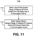
Figure 11 illustrates another embodiment for increasing dynamic range of a particle sensor while maintaining broad range ofsensitivity 1100. To the extent that the embodiment ofmethod 1100 shown inFigure 1 is described herein as being implemented in the systems shown inFigures 1 through 8 , and10 , it is to be understood that other embodiments can be implemented in other ways. The blocks of the flow diagrams have been arranged in a generally sequential manner for ease of explanation; however, it is to be understood that this arrangement is merely exemplary, and it should be recognized that the processing associated with the methods (and the blocks shown in the Figure) can occur in a different order (for example, where at least some of the processing associated with the blocks is performed in parallel and/or in an event-driven manner). - In
block 1113, detect a presence of a first particle of a first particle size in a first interrogation volume. In one embodiment, detecting the presence of the first particle of the first particle size in the first interrogation volume comprises detecting during a first time period. In another embodiment, detecting the presence of the first particle of the first particle size in the first interrogation volume comprises detecting at least one of (a) intensity of scattered light and (b) relative polarization of scattered light. - In
block 1115, detect a presence of a second particle of a second particle size in the first interrogation volume. In one embodiment, detecting the presence of the second particle of the second particle size in the first interrogation volume comprises detecting during a second time period subsequent to the first time period. In another embodiment, the first time period and the second time period sequentially repeat. In a further embodiment, the duty cycle is smaller for the for the time period corresponding to an interrogation volume used to detect larger particles. In yet another embodiment, detecting the presence of the second particle of the second particle size in the first interrogation volume comprises detecting at least one of (a) intensity of scattered light and (b) relative polarization of the scattered light. In yet a further embodiment, blocks 990 and 992 are performed by at least one transmitter, e.g. a LASER, and at least one receiver, e.g. an optical receiver. - Although specific embodiments have been illustrated and described herein, it will be appreciated by those of ordinary skill in the art that any arrangement, which is calculated to achieve the same purpose, may be substituted for the specific embodiments shown. Therefore, it is manifestly intended that this invention be limited only by the claims and the equivalents thereof.
-
- Example 1 includes a particle detection system, comprising: at least one transmitter; at least one receiver; a first interrogation volume formed by a first intersection of a first pair of a transmitter beam of a transmitter and a receiver field of view of a receiver; and a second interrogation volume formed by a second intersection of a second pair of a transmitter beam of a transmitter and a receiver field of view of a receiver.
- Example 2 includes the particle detection system of Example 1, wherein the at least one receiver is configured to: detect a presence of a first particle of a first particle size in the first interrogation volume; and detect presence of a second particle of a second particle size in the second interrogation volume.
- Example 3 includes the particle detection system of Examples 1-2, wherein detect the presence of the first particle comprises detect at least one of (a) an intensity of scattered light and (b) a relative polarization of the scattered light; and where detect the presence of the second particle comprises detect at least one of (a) an intensity of scattered light and (b) a relative polarization of the scattered light.
- Example 4 includes the particle detection system of Example 1, wherein the at least one receiver comprises an optical receiver comprising: a slit; collection optics which collects light through the receiver field of view and focuses it upon the slit; and an optical detection system which receives light from the slit.
- Example 5 includes the particle detection system of Example 1, wherein the at least one transmitter consists of a transmitter; wherein the transmitter beam of the first pair and the transmitter beam of the second pair are the same transmitter beam; wherein the at least one receiver comprises at least two receivers; and wherein the receiver field of view of the first pair and the receiver field of view of the second pair are different receiver field of views.
- Example 6 includes the particle detection system of Example 1, wherein the at least one transmitter comprises at least two transmitters; wherein the transmitter beam of the first pair and the transmitter beam of the second pair are different transmitter beams; wherein the at least one receiver consists of a receiver; and wherein the receiver field of view of the first pair and the receiver field of view of the second pair are the same receiver field of view.
- Example 7 includes the particle detection system of Examples 1-6, wherein each of the at least two transmitters generates optical signals having a unique frequency or frequency band; and wherein the one receiver comprises: collection optics which collects light through a receiver field of view and collimates such light; a dichromatic beam splitter configured to direct optical signals of different frequencies or frequency bands in different directions; a first receiver system configured to receive an optical signal of a first frequency or a first frequency band; and a second receiver system configured to receive an optical signal of a second frequency or a second frequency band.
- Example 8 includes the particle detection system of Examples 1-7, wherein the first receiver system and the second receiver system each comprise: a slit; a first focusing lens configured to focus collimated light onto the slit; and an optical detection system configured to receive light from the slit.
- Example 9 includes the particle detection system of Example 1, wherein the at least one transmitter consists of a transmitter; and wherein the at least one receiver consists of a receiver.
- Example 10 includes the particle detection system of Examples 1-9, wherein the receiver comprises: a first slit; a second slit; collection optics which (a) collects light through a first receiver field of view and focuses it upon the first slit, and (b) collects light through a second receiver field of view and focuses it upon the second slit; a first optical detection system which receives light from the first slit; a second optical detection system which receives light from the second slit; wherein the transmitter beam of the first pair and the transmitter beam of the second pair are the same transmitter beam; and wherein the receiver field of view of the first pair is the first receiver field of view and the receiver field of view of the second pair is the second receiver field of view.
- Example 11 includes the particle detection system of Examples 1-9, wherein the receiver field of view of the first pair and the receiver field of view of the second pair are sequenced; wherein the transmitter beam of the first pair and the transmitter beam of the second pair are the same transmitter beam; and wherein the receiver field of view of the first pair and the receiver field of view of the second pair are different receiver field of views.
- Example 12 includes the particle detection system of Examples 1-9, wherein the transmitter field of view of the first pair and the transmitter field of view of the second pair are sequenced; wherein the receiver field of view of the first pair and the receiver field of view of the second pair are the same receiver field of view; and wherein the transmitter beam of the first pair and the transmitter beam of the second pair are different transmitter beams.
- Example 13 includes a method, comprising: detecting presence of a first particle of a first particle size in a first interrogation volume; and detecting presence of a second particle of a second particle size in a second interrogation volume.
- Example 14 includes the method of Example 13, further comprising: wherein detecting the presence of the first particle comprises detecting at least one of (a) an intensity of scattered light and (b) a relative polarization of the scattered light; and wherein detecting the presence of the second particle comprises detecting at least one of (a) an intensity of scattered light and (b) a relative polarization of the scattered light.
- Example 15 includes the method of Example 13, wherein detecting the presence of the first particle in the first interrogation volume comprises detecting the presence of the first particle sequentially in time with detecting the presence of the second particle.
- Example 16 includes a particle detection system, comprising: a transmitter; a receiver; an interrogation volume formed by an intersection of a transmitter beam of the transmitter and the receiver field of view of a receiver; and at least one amplifier system, coupled to the receiver, configured to output at least one signal which has been amplified by different gain levels.
- Example 17 includes the particle detection system of Example 16, wherein the at least one amplifier system has at least two outputs.
- Example 18 includes a method, comprising: detecting, using a first detection dynamic range, a presence of a first particle of a first particle size in an interrogation volume; and detecting, using a second detection dynamic range, a presence of a second particle of a second particle size in the interrogation volume.
- Example 19 includes the method of Example 18, wherein detecting, using the first detection dynamic range, the presence of the first particle comprises detecting at least one of (a) an intensity of scattered light and (b) a relative polarization of the scattered light; and wherein detecting, using the second detection dynamic range, the presence of the second particle comprises detecting at least one of (a) an intensity of scattered light and (b) a relative polarization of the scattered light.
- Example 20 includes the method of Examples 18-19, wherein detecting, using the first detection dynamic range, the presence of the first particle in the first interrogation volume comprises detecting the presence of the first particle sequentially in time with detecting, using the second detection dynamic range, the presence of the second particle.
- Although specific embodiments have been illustrated and described herein, it will be appreciated by those of ordinary skill in the art that any arrangement, which can achieve the same purpose, may be substituted for the specific embodiments shown. Therefore, it is manifestly intended that this invention be limited only by the claims and the equivalents thereof.
Claims (10)
- A particle detection system (100, 300, 400, 600, 800) comprising:at least one transmitter;at least one receiver;a first interrogation volume (110A, 310A, 410A, 610A, 810A) formed by a first intersection of a first pair of a transmitter beam of a transmitter and a receiver field of view of a receiver; anda second interrogation volume (110B, 310B, 410B, 610B, 810B) formed by a second intersection of a second pair of a transmitter beam of a transmitter and a receiver field of view of a receiver.
- The particle detection system of claim 1, wherein the at least one receiver is configured to:detect a presence of a first particle of a first particle size in the first interrogation volume; anddetect presence of a second particle of a second particle size in the second interrogation volume.
- The particle detection system of claim 1, wherein the at least one receiver comprises an optical receiver comprising:a slit (224, 523A, 523B);collection optics (220, 520) which collects light through the receiver field of view and focuses it upon the slit; andan optical detection system (229, 529A, 529B) which receives light from the slit.
- The particle detection system of claim 1, wherein the at least one transmitter consists of a transmitter (302);
wherein the transmitter beam of the first pair and the transmitter beam of the second pair are the same transmitter beam;
wherein the at least one receiver comprises at least two receivers (304A, 304B); and
wherein the receiver field of view of the first pair and the receiver field of view of the second pair are different receiver field of views. - The particle detection system of claim 1, wherein the at least one transmitter comprises at least two transmitters (402A, 402B)
wherein the transmitter beam of the first pair and the transmitter beam of the second pair are different transmitter beams;
wherein the at least one receiver consists of a receiver (404); and
wherein the receiver field of view of the first pair and the receiver field of view of the second pair are the same receiver field of view. - The particle detection system of claim 1, wherein the at least one transmitter consists of a transmitter (602, 802); and
wherein the at least one receiver consists of a receiver (602, 802). - The particle detection system of claim 1, wherein the receiver comprises:a first slit (723A);a second slit (723B);collection optics (720) which (a) collects light through a first receiver field of view and focuses it upon the first slit, and (b) collects light through a second receiver field of view and focuses it upon the second slit;a first optical detection system (729A)which receives light from the first slit;a second optical detection system (729B) which receives light from the second slit;wherein the transmitter beam of the first pair and the transmitter beam of the second pair are the same transmitter beam; andwherein the receiver field of view of the first pair is the first receiver field of view and the receiver field of view of the second pair is the second receiver field of view.
- The particle detection system of claim 1, wherein the receiver or one or more components of the receiver are moved between at least two positions;
wherein the transmitter beam of the first pair and the transmitter beam of the second pair are the same transmitter beam; and
wherein the receiver field of view of the first pair and the receiver field of view of the second pair are different receiver field of views. - The particle detection system of claim 1, wherein the transmitter or one or more components of the transmitter are moved between at least two positions;
wherein the receiver field of view of the first pair and the receiver field of view of the second pair are the same receiver field of view; and
wherein the transmitter beam of the first pair and the transmitter beam of the second pair are different transmitter beams. - A method, comprising:detecting, using a first detection dynamic range, a presence of a first particle of a first particle size in an interrogation volume (1113); anddetecting, using a second detection dynamic range, a presence of a second particle of a second particle size in the interrogation volume (1115).
Applications Claiming Priority (1)
| Application Number | Priority Date | Filing Date | Title |
|---|---|---|---|
| US15/725,687 US10591422B2 (en) | 2017-10-05 | 2017-10-05 | Apparatus and method for increasing dynamic range of a particle sensor |
Publications (2)
| Publication Number | Publication Date |
|---|---|
| EP3477277A2 true EP3477277A2 (en) | 2019-05-01 |
| EP3477277A3 EP3477277A3 (en) | 2019-07-31 |
Family
ID=63762326
Family Applications (1)
| Application Number | Title | Priority Date | Filing Date |
|---|---|---|---|
| EP18198519.3A Withdrawn EP3477277A3 (en) | 2017-10-05 | 2018-10-03 | Apparatus and method for increasing dynamic range of a particle sensor |
Country Status (4)
| Country | Link |
|---|---|
| US (1) | US10591422B2 (en) |
| EP (1) | EP3477277A3 (en) |
| JP (1) | JP7256625B2 (en) |
| IL (1) | IL260362B2 (en) |
Cited By (1)
| Publication number | Priority date | Publication date | Assignee | Title |
|---|---|---|---|---|
| WO2021078805A1 (en) * | 2019-10-25 | 2021-04-29 | Commissariat A L'energie Atomique Et Aux Energies Alternatives | Optical detector of particles |
Families Citing this family (5)
| Publication number | Priority date | Publication date | Assignee | Title |
|---|---|---|---|---|
| US11879822B2 (en) * | 2018-06-01 | 2024-01-23 | Horiba, Ltd. | Particle size distribution measuring device and program for particle size distribution measuring device |
| US10656084B2 (en) * | 2018-06-14 | 2020-05-19 | Rosemount Aerospace Inc. | System and method for measuring cloud parameters |
| US11630216B2 (en) | 2019-08-23 | 2023-04-18 | Rosemount Aerospace Inc. | Characterization of a cloud atmosphere using light backscattered at two angles |
| US11959847B2 (en) * | 2019-09-12 | 2024-04-16 | Cytonome/St, Llc | Systems and methods for extended dynamic range detection of light |
| US11912419B2 (en) * | 2022-01-21 | 2024-02-27 | Honeywell International Inc. | Ice protection modulation with atmospheric conditions |
Family Cites Families (38)
| Publication number | Priority date | Publication date | Assignee | Title |
|---|---|---|---|---|
| US4934811A (en) * | 1988-04-01 | 1990-06-19 | Syntex (U.S.A.) Inc. | Apparatus and method for detection of fluorescence or light scatter |
| DE68924749T2 (en) | 1988-09-15 | 1996-07-04 | Univ Arkansas | Identification of particles by modulated dynamic light scattering. |
| US4953978A (en) * | 1989-03-03 | 1990-09-04 | Coulter Electronics Of New England, Inc. | Particle size analysis utilizing polarization intensity differential scattering |
| US5110204A (en) * | 1990-11-06 | 1992-05-05 | Trustees Of Princeton University | Velocity measurement by the vibrational tagging of diatomic molecules |
| US6560349B1 (en) * | 1994-10-21 | 2003-05-06 | Digimarc Corporation | Audio monitoring using steganographic information |
| US5528045A (en) * | 1995-04-06 | 1996-06-18 | Becton Dickinson And Company | Particle analyzer with spatially split wavelength filter |
| US5835211A (en) * | 1996-03-28 | 1998-11-10 | Particle Sizing Systems, Inc. | Single-particle optical sensor with improved sensitivity and dynamic size range |
| FR2807522B1 (en) | 2000-04-07 | 2002-06-14 | Aerospatiale Matra Airbus | DEVICE FOR DETERMINING THE VALUES OF AT LEAST ONE PARAMETER OF PARTICLES, ESPECIALLY WATER DROPLETS |
| US6831279B2 (en) * | 2001-11-27 | 2004-12-14 | Her Majesty The Queen In Right Of Canada, As Represented By The Minister Of National Defence | Laser diode-excited biological particle detection system |
| DE10202999B4 (en) | 2002-01-26 | 2004-04-15 | Palas Gmbh Partikel- Und Lasermesstechnik | Method and device for measuring the size distribution and concentration of particles in a fluid |
| GB0223512D0 (en) * | 2002-10-10 | 2002-11-13 | Qinetiq Ltd | Bistatic laser radar apparatus |
| US6859276B2 (en) * | 2003-01-24 | 2005-02-22 | Coulter International Corp. | Extracted polarization intensity differential scattering for particle characterization |
| JP4598766B2 (en) * | 2003-04-29 | 2010-12-15 | エス3アイ, エル エル シィ | Multispectral optical method and system for detecting and classifying biological and non-biological microparticles |
| WO2005019419A2 (en) * | 2003-07-31 | 2005-03-03 | Singulex, Inc. | Co-detection of single polypeptide and polynucleotide molecules |
| US20080021674A1 (en) * | 2003-09-30 | 2008-01-24 | Robert Puskas | Methods for Enhancing the Analysis of Particle Detection |
| US20070242269A1 (en) | 2004-03-06 | 2007-10-18 | Michael Trainer | Methods and apparatus for determining characteristics of particles |
| US8634072B2 (en) | 2004-03-06 | 2014-01-21 | Michael Trainer | Methods and apparatus for determining characteristics of particles |
| US9493769B2 (en) * | 2004-06-02 | 2016-11-15 | Universite D'aix-Marseille | Yeast-based assay for measuring the functional activity of an HIV-1 protease in response to an antiviral agent |
| JP2008514955A (en) * | 2004-09-28 | 2008-05-08 | シンギュレックス・インコーポレイテッド | Sample analysis system and method |
| US7339670B2 (en) | 2005-07-29 | 2008-03-04 | Lockheed Martin Coherent Technologies, Inc. | Wavelength normalized depolarization ratio lidar |
| JP2007327889A (en) | 2006-06-08 | 2007-12-20 | Koito Ind Ltd | Volcanic ash detector and weather condition determination apparatus |
| JP4931502B2 (en) | 2006-07-13 | 2012-05-16 | 株式会社日立ハイテクノロジーズ | Surface inspection method and inspection apparatus |
| DE102007013321A1 (en) | 2007-03-20 | 2008-09-25 | Jenoptik Laser, Optik, Systeme Gmbh | Apparatus and method for determining particle size and / or particle shape of a particle mixture |
| US7932490B2 (en) * | 2007-08-07 | 2011-04-26 | Tsi, Inc. | Size segregated aerosol mass concentration measurement device |
| US8047055B2 (en) * | 2007-08-08 | 2011-11-01 | Tsi, Incorporated | Size segregated aerosol mass concentration measurement with inlet conditioners and multiple detectors |
| US8804119B2 (en) | 2008-06-10 | 2014-08-12 | Xtralis Technologies Ltd | Particle detection |
| DE102008038216A1 (en) * | 2008-08-18 | 2010-03-11 | Carl Zeiss Nts Gmbh | A method of generating corpuscular beam images with a corpuscular beam apparatus |
| US7932495B2 (en) * | 2008-09-02 | 2011-04-26 | ICT Integrated Circuit Testing Gesellschaft für Halbleiterprüftechnik mbH | Fast wafer inspection system |
| WO2010080643A1 (en) | 2008-12-18 | 2010-07-15 | Biovigilant Systems, Inc. | Integrated microbial collector |
| DE102009014080B4 (en) * | 2009-03-23 | 2011-12-15 | Baumer Innotec Ag | Device for determining particle sizes |
| CN102612652B (en) * | 2009-08-06 | 2016-05-04 | 康奈尔大学 | For equipment and the method for analysis of molecules |
| US20130342684A1 (en) | 2011-01-19 | 2013-12-26 | Teknologian Tutkimuskeskus Vtt | Method and System for Determining Particle Size Information |
| US9222873B2 (en) | 2013-05-02 | 2015-12-29 | Droplet Measurement Technologies, Inc. | Optical particle detector |
| DE102014017552A1 (en) | 2014-10-15 | 2016-04-21 | Retsch Technology Gmbh | Apparatus and method for determining particle size and / or particle shape of particles in a particle stream |
| WO2017060105A1 (en) | 2015-10-08 | 2017-04-13 | Koninklijke Philips N.V. | Particle sensor for particle detection |
| WO2017162677A1 (en) | 2016-03-21 | 2017-09-28 | Koninklijke Philips N.V. | Laser sensor for ultra-fine particle size detection |
| US9851291B2 (en) * | 2016-05-02 | 2017-12-26 | Hamilton Associates, Inc. | Realtime optical method and system for detecting and classifying biological and non-biological particles |
| WO2018052798A1 (en) * | 2016-09-13 | 2018-03-22 | Becton, Dickinson And Company | Flow cytometer with optical equalization |
-
2017
- 2017-10-05 US US15/725,687 patent/US10591422B2/en active Active
-
2018
- 2018-07-02 IL IL260362A patent/IL260362B2/en unknown
- 2018-10-03 JP JP2018188048A patent/JP7256625B2/en active Active
- 2018-10-03 EP EP18198519.3A patent/EP3477277A3/en not_active Withdrawn
Non-Patent Citations (1)
| Title |
|---|
| None |
Cited By (2)
| Publication number | Priority date | Publication date | Assignee | Title |
|---|---|---|---|---|
| WO2021078805A1 (en) * | 2019-10-25 | 2021-04-29 | Commissariat A L'energie Atomique Et Aux Energies Alternatives | Optical detector of particles |
| FR3102559A1 (en) * | 2019-10-25 | 2021-04-30 | Commissariat A L'energie Atomique Et Aux Energies Alternatives | multi-particle detector |
Also Published As
| Publication number | Publication date |
|---|---|
| US10591422B2 (en) | 2020-03-17 |
| JP2019090787A (en) | 2019-06-13 |
| EP3477277A3 (en) | 2019-07-31 |
| IL260362A (en) | 2018-11-29 |
| JP7256625B2 (en) | 2023-04-12 |
| IL260362B2 (en) | 2023-06-01 |
| US20190107496A1 (en) | 2019-04-11 |
Similar Documents
| Publication | Publication Date | Title |
|---|---|---|
| EP3477277A2 (en) | Apparatus and method for increasing dynamic range of a particle sensor | |
| US10585029B2 (en) | Analysis device for determining particulate matter | |
| CN111122496B (en) | Calibration-free gas concentration measuring device and method | |
| US8675184B2 (en) | Direct detection Doppler LIDAR method and direction detection Doppler LIDAR device | |
| US7397568B2 (en) | Coherent differential absorption lidar (dial) | |
| US8405011B2 (en) | Target tracking device and method | |
| US10054529B2 (en) | Particle counter | |
| CN109900602B (en) | Particle counter | |
| US6285288B1 (en) | Remote air detection | |
| CN102175591A (en) | Laser forward-scattering cloud droplet spectrum probing system | |
| JPH02134540A (en) | Fine particle measuring apparatus | |
| CN110243729B (en) | Particle counter | |
| JP2016224009A (en) | Signal processor and method for determining noise intensity | |
| US7675619B2 (en) | Micro-LiDAR velocity, temperature, density, concentration sensor | |
| CN110398749B (en) | Double oblique incidence asymmetric vehicle-mounted laser speed measuring device | |
| US11346773B2 (en) | Fabry-Perot spectrometer-based smoke detector | |
| US11650323B2 (en) | Meteorological lidar | |
| CN112904308A (en) | Laser radar system and method for detecting cloud phase state and cloud water content | |
| CN218917631U (en) | Atmospheric detection laser radar | |
| CN114674292B (en) | System and method for detecting ocean optical profile based on airborne multi-wavelength laser radar | |
| RU175866U1 (en) | Cloud meter | |
| CN115128639B (en) | Differential absorption laser radar capable of adjusting seed optical power in real time | |
| KR102500960B1 (en) | Particulates measuring method and particulates measuring device | |
| CN115774271A (en) | Laser radar for atmospheric detection | |
| CN115773864A (en) | Method for measuring total integral scattering of high-reflection optical element based on cavity ring-down technology |
Legal Events
| Date | Code | Title | Description |
|---|---|---|---|
| PUAI | Public reference made under article 153(3) epc to a published international application that has entered the european phase |
Free format text: ORIGINAL CODE: 0009012 |
|
| STAA | Information on the status of an ep patent application or granted ep patent |
Free format text: STATUS: REQUEST FOR EXAMINATION WAS MADE |
|
| STAA | Information on the status of an ep patent application or granted ep patent |
Free format text: STATUS: REQUEST FOR EXAMINATION WAS MADE |
|
| 17P | Request for examination filed |
Effective date: 20181003 |
|
| AK | Designated contracting states |
Kind code of ref document: A2 Designated state(s): AL AT BE BG CH CY CZ DE DK EE ES FI FR GB GR HR HU IE IS IT LI LT LU LV MC MK MT NL NO PL PT RO RS SE SI SK SM TR |
|
| AX | Request for extension of the european patent |
Extension state: BA ME |
|
| PUAL | Search report despatched |
Free format text: ORIGINAL CODE: 0009013 |
|
| AK | Designated contracting states |
Kind code of ref document: A3 Designated state(s): AL AT BE BG CH CY CZ DE DK EE ES FI FR GB GR HR HU IE IS IT LI LT LU LV MC MK MT NL NO PL PT RO RS SE SI SK SM TR |
|
| AX | Request for extension of the european patent |
Extension state: BA ME |
|
| RIC1 | Information provided on ipc code assigned before grant |
Ipc: G01N 15/14 20060101AFI20190626BHEP |
|
| STAA | Information on the status of an ep patent application or granted ep patent |
Free format text: STATUS: EXAMINATION IS IN PROGRESS |
|
| 17Q | First examination report despatched |
Effective date: 20210611 |
|
| STAA | Information on the status of an ep patent application or granted ep patent |
Free format text: STATUS: THE APPLICATION HAS BEEN WITHDRAWN |
|
| 18W | Application withdrawn |
Effective date: 20210909 |
|
| P01 | Opt-out of the competence of the unified patent court (upc) registered |
Effective date: 20230525 |