EP3477194B1 - Detachable warning lamp - Google Patents
Detachable warning lamp Download PDFInfo
- Publication number
- EP3477194B1 EP3477194B1 EP17197984.2A EP17197984A EP3477194B1 EP 3477194 B1 EP3477194 B1 EP 3477194B1 EP 17197984 A EP17197984 A EP 17197984A EP 3477194 B1 EP3477194 B1 EP 3477194B1
- Authority
- EP
- European Patent Office
- Prior art keywords
- base
- light
- emitting elements
- inner bottom
- cover
- Prior art date
- Legal status (The legal status is an assumption and is not a legal conclusion. Google has not performed a legal analysis and makes no representation as to the accuracy of the status listed.)
- Active
Links
- 230000000717 retained effect Effects 0.000 description 3
- 239000003595 mist Substances 0.000 description 1
Images




Classifications
-
- F—MECHANICAL ENGINEERING; LIGHTING; HEATING; WEAPONS; BLASTING
- F21—LIGHTING
- F21V—FUNCTIONAL FEATURES OR DETAILS OF LIGHTING DEVICES OR SYSTEMS THEREOF; STRUCTURAL COMBINATIONS OF LIGHTING DEVICES WITH OTHER ARTICLES, NOT OTHERWISE PROVIDED FOR
- F21V15/00—Protecting lighting devices from damage
- F21V15/01—Housings, e.g. material or assembling of housing parts
-
- B—PERFORMING OPERATIONS; TRANSPORTING
- B60—VEHICLES IN GENERAL
- B60Q—ARRANGEMENT OF SIGNALLING OR LIGHTING DEVICES, THE MOUNTING OR SUPPORTING THEREOF OR CIRCUITS THEREFOR, FOR VEHICLES IN GENERAL
- B60Q1/00—Arrangement of optical signalling or lighting devices, the mounting or supporting thereof or circuits therefor
- B60Q1/26—Arrangement of optical signalling or lighting devices, the mounting or supporting thereof or circuits therefor the devices being primarily intended to indicate the vehicle, or parts thereof, or to give signals, to other traffic
- B60Q1/2611—Indicating devices mounted on the roof of the vehicle
-
- F—MECHANICAL ENGINEERING; LIGHTING; HEATING; WEAPONS; BLASTING
- F21—LIGHTING
- F21V—FUNCTIONAL FEATURES OR DETAILS OF LIGHTING DEVICES OR SYSTEMS THEREOF; STRUCTURAL COMBINATIONS OF LIGHTING DEVICES WITH OTHER ARTICLES, NOT OTHERWISE PROVIDED FOR
- F21V19/00—Fastening of light sources or lamp holders
- F21V19/001—Fastening of light sources or lamp holders the light sources being semiconductors devices, e.g. LEDs
- F21V19/003—Fastening of light source holders, e.g. of circuit boards or substrates holding light sources
-
- F—MECHANICAL ENGINEERING; LIGHTING; HEATING; WEAPONS; BLASTING
- F21—LIGHTING
- F21V—FUNCTIONAL FEATURES OR DETAILS OF LIGHTING DEVICES OR SYSTEMS THEREOF; STRUCTURAL COMBINATIONS OF LIGHTING DEVICES WITH OTHER ARTICLES, NOT OTHERWISE PROVIDED FOR
- F21V19/00—Fastening of light sources or lamp holders
- F21V19/001—Fastening of light sources or lamp holders the light sources being semiconductors devices, e.g. LEDs
- F21V19/003—Fastening of light source holders, e.g. of circuit boards or substrates holding light sources
- F21V19/004—Fastening of light source holders, e.g. of circuit boards or substrates holding light sources by deformation of parts or snap action mountings, e.g. using clips
-
- F—MECHANICAL ENGINEERING; LIGHTING; HEATING; WEAPONS; BLASTING
- F21—LIGHTING
- F21V—FUNCTIONAL FEATURES OR DETAILS OF LIGHTING DEVICES OR SYSTEMS THEREOF; STRUCTURAL COMBINATIONS OF LIGHTING DEVICES WITH OTHER ARTICLES, NOT OTHERWISE PROVIDED FOR
- F21V19/00—Fastening of light sources or lamp holders
- F21V19/001—Fastening of light sources or lamp holders the light sources being semiconductors devices, e.g. LEDs
- F21V19/003—Fastening of light source holders, e.g. of circuit boards or substrates holding light sources
- F21V19/0045—Fastening of light source holders, e.g. of circuit boards or substrates holding light sources by tongue and groove connections, e.g. dovetail interlocking means fixed by sliding
-
- F—MECHANICAL ENGINEERING; LIGHTING; HEATING; WEAPONS; BLASTING
- F21—LIGHTING
- F21Y—INDEXING SCHEME ASSOCIATED WITH SUBCLASSES F21K, F21L, F21S and F21V, RELATING TO THE FORM OR THE KIND OF THE LIGHT SOURCES OR OF THE COLOUR OF THE LIGHT EMITTED
- F21Y2115/00—Light-generating elements of semiconductor light sources
- F21Y2115/10—Light-emitting diodes [LED]
Definitions
- the present invention relates to a detachable warning lamp, and more particularly to a detachable warning lamp that is convenient to detach.
- a conventional detachable warning lamp has a base, a light-emitting module, and a cover.
- the base has a chamber, two side surfaces, a top surface, two side openings, and a top opening.
- the chamber is formed in the base.
- the two side surfaces are opposite to each other.
- the top surface is connected to the two side surfaces.
- the two side openings are respectively formed on the two side surfaces of the base, and are in communication with the chamber of the base.
- the top opening is formed through the top surface of the base and is in communication with the chamber.
- the base has two mounting plates.
- the two mounting plates are disposed in the chamber of the base, and respectively face the two side openings of the base.
- the light-emitting module is disposed on the base and has a circuit board and multiple light-emitting elements.
- the circuit board is disposed in the chamber of the base.
- the light-emitting elements are screwed on the two mounting plates and face an adjacent one of the side openings.
- the light-emitting elements are electrically connected to the circuit board.
- the cover is disposed on the base and covers the top opening of the base.
- the light-emitting elements are detachably disposed on the two mounting plates of the base.
- a hand tool is controlled by users for driving the screws.
- the light-emitting elements are screwed on the two mounting plates by the screws.
- disassembly the screws are detached from the two mounting plates by the hand tool, and then the light-emitting elements are detached from the two mounting plates.
- Document KR 10-0963584 B discloses a warning lamp.
- the present invention provides a detachable warning lamp to mitigate or obviate the aforementioned problems.
- the objective of the invention is to provide a detachable warning lamp that can be easily assembled and save time.
- the detachable warning lamp has a base, a light-emitting module, and a cover.
- the base has a chamber, two side surfaces, a top surface, an inner bottom surface, two side openings, a top opening, two retaining walls, and two engaging grooves.
- the chamber is formed in the base.
- the two side surfaces of the base are opposite to each other.
- the top surface of the base is formed across the two side surfaces of the base.
- the inner bottom surface of the base is formed in the base and is disposed adjacent to the chamber of the base.
- the two side openings are respectively formed through the two side surfaces of the base and are in communication with the chamber of the base.
- the top opening is formed through the top surface of the base and is in communication with the chamber of the base.
- the two retaining walls are formed on the inner bottom surface of the base adjacent to the two side openings of the base respectively.
- the two engaging grooves are formed on the inner bottom surface of the base adjacent to the two side openings of the base respectively. Each one of the two engaging grooves is respectively located between a corresponding one of the two retaining walls and a corresponding one of the two side openings of the base.
- the light-emitting module is disposed on the base and has a circuit board and multiple light-emitting elements.
- the circuit board is disposed on the base and is located in the chamber of the base.
- the light-emitting elements are electrically connected to the circuit board and are detachably disposed in the two side openings of the base.
- Each one of the light-emitting elements has a shell, a first engaging portion, multiple first cushioning lugs, a second engaging portion, and multiple second cushioning lugs.
- the shell has a bottom surface, a top surface, and a rear surface.
- the first engaging portion is formed on the bottom surface of the shell and is inserted into a corresponding one of the two engaging grooves.
- the first cushioning lugs are formed on and protrude out of the rear surface of the shell.
- the first cushioning lugs abut a corresponding one of the two retaining walls.
- the second engaging portion is formed on the top surface of the shell and is located above the first engaging portion.
- the second cushioning lugs are formed on and protrude out of the rear surface of the shell, and are located above the first cushioning lugs.
- the cover is disposed on the base, covers the top opening of the base, and has an inner bottom surface, two baffles, and two stopping surfaces.
- the inner bottom surface of the cover faces the inner bottom surface of the base.
- the two baffles are formed on the inner bottom surface of the cover and are respectively disposed adjacent to the side openings of the base, and each baffle abuts the second cushioning lugs of a corresponding one of the light-emitting elements.
- the two stopping surfaces are formed on the inner bottom surface of the cover and respectively face the two baffles, and each stopping surface abuts the second engaging portion of a corresponding one of the light-emitting elements.
- each one of the first cushioning lugs abuts the corresponding one of the two retaining walls of the base and is deformed for providing a restoring force.
- the first engaging portion is inserted into the corresponding one of the two engaging grooves of the base.
- the light-emitting elements can be engaged with and retained on the base.
- the cover is disposed on the base and covers the light-emitting elements.
- the light-emitting elements are disposed between the base and the cover.
- each one of the second cushioning lugs abuts the corresponding one of the two baffles of the cover.
- the second engaging portion abuts the corresponding one of the two stopping surfaces of the cover. Therefore, the light-emitting elements are easy to assemble, and the assembly time of the light-emitting elements is saved.
- the cover is detached from the base.
- the light-emitting elements may be pushed toward the chamber.
- the first cushioning lugs of the light-emitting elements are deformed.
- the first engaging portions of the light-emitting elements move out of the engaging grooves by the movements of the light-emitting elements.
- the light-emitting elements can be detached from the base. Therefore, the light-emitting elements are easy to detach, saving the time for disassembly.
- the light-emitting elements are detachably engaged with the base without the use of a screw and a hand tool.
- the detachable warning lamp is easy to assemble and detach, saving the time for assembly and disassembly.
- a detachable warning lamp in accordance with the present invention comprises a base 10, a light-emitting module 20, and a cover 30.
- the base 10 has a chamber 11, two side surfaces, a top surface, an inner bottom surface, two side openings 12, a top opening 13, two retaining walls 14, and two engaging grooves 15.
- the chamber 11 is formed in the base 10.
- the two side surfaces of the base 10 are opposite to each other.
- the top surface of the base 10 is formed across the two side surfaces of the base 10.
- the inner bottom surface of the base 10 is formed in the base 10 and is disposed adjacent to the chamber 11 of the base 10.
- the two side openings 12 are respectively formed through the two side surfaces of the base 10, and are in communication with the chamber 11 of the base 10.
- the top opening 13 is formed through the top surface of the base 10 and is in communication with the chamber 11 of the base 10.
- the two retaining walls 14 are formed on the inner bottom surface of the base 10 adjacent to the two side openings 12 of the base 10 respectively.
- the two engaging grooves 15 are formed on the inner bottom surface of the base 10 adjacent to the two side openings 12 of the base 10 respectively. Each one of the two engaging grooves 15 is respectively located between a corresponding one of the two retaining walls 14 of the base 10 and a corresponding one of the two side openings 12 of the base 10.
- the light-emitting module 20 is disposed on the base 10 and has a circuit board 21 and multiple light-emitting elements 22.
- the circuit board 21 is disposed on the base 10, and is located in the chamber 11 of the base 10.
- the light-emitting elements 22 are electrically connected to the circuit board 21 and are detachably disposed in the two side openings 12 of the base 10.
- each one of the light-emitting elements 22 has a shell 23, a first engaging portion 24, multiple first cushioning lugs 25, a second engaging portion 26, and multiple second cushioning lugs 27.
- the shell 23 has a bottom surface, a top surface, and a rear surface.
- the first engaging portion 24 is formed on the bottom surface of the shell 23 and is inserted into a corresponding one of the two engaging grooves 15.
- the first cushioning lugs 25 are formed on and protrude out of the rear surface of the shell 23.
- the first cushioning lugs 25 abut a corresponding one of the two retaining walls 14.
- the second engaging portion 26 is formed on the top surface of the shell 23, and is located above the first engaging portion 24.
- the second cushioning lugs 27 are formed on and protrude out of the rear surface of the shell 23, and are located above the first cushioning lugs 25.
- the cover 30 is disposed on the base 10, covers the top opening 13 of the base 10, and has an inner bottom surface, two baffles 31, and two stopping surfaces 32.
- the inner bottom surface of the cover 30 faces the inner bottom surface of the base 10.
- the two baffles 31 are formed on the inner bottom surface of the cover 30 and are respectively disposed adjacent to the side openings 12 of the base 10, and each baffle 31 abuts the second cushioning lugs 27 of a corresponding one of the light-emitting elements 22.
- the two stopping surfaces 32 are formed on the inner bottom surface of the cover 30 and respectively face the two baffles 31, and each stopping surface 32 abuts the second engaging portion 26 of a corresponding one of the light-emitting elements 22.
- the base 10 has two first leak-proof grooves 16.
- the two first leak-proof grooves 16 are formed on the inner bottom surface of the base 10, and are located between the two engaging grooves 15 and the two side openings 12 of the base 10.
- the cover 30 has two second leak-proof grooves 33.
- the two second leak-proof grooves 33 are formed on the inner bottom surface of the cover 30, and are located between the two stopping surfaces 32 of the cover 30 and the two side openings 12 of the base 10.
- the detachable warning lamp has four waterproof strips 40. The four waterproof strips 40 are respectively disposed on the two first leak-proof grooves 16 of the base 10 and the two second leak-proof grooves 33 of the cover 30.
- each one of the light-emitting elements 22 has multiple first deforming spaces 28 and multiple second deforming spaces 29.
- the first deforming spaces 28 are respectively formed between the first cushioning lugs 25 and the rear surface of the shell 23.
- the second deforming spaces 29 are respectively formed between the second cushioning lugs 27 and the rear surface of the shell 23.
- the light-emitting elements 22 are detachably engaged with the base 10 one by one, and then the cover 30 is disposed on the base 10.
- the light-emitting elements 22 are disposed between the base 10 and the cover 30 for fixing the light-emitting elements 22.
- the first cushioning lugs 25 abut the retaining walls 14 of the base 10.
- Each one of the light-emitting elements 22 is pushed by the users.
- Each one of the first cushioning lugs 25 is deformed and provides a restoring force.
- the first engaging portion 24 is inserted into the corresponding one of the two engaging grooves 15.
- Each one of the light-emitting elements 22 is moved out of the base 10 by the restoring force.
- the light-emitting elements 22 are engaged with and retained on the base 10.
- the cover 30 is disposed on the base 10 and covers the light-emitting elements 22.
- the second cushioning lugs 27 of the light-emitting elements 22 abut the baffles 31 of the cover 30.
- the second engaging portions 26 of the light-emitting elements 22 abut the stopping surfaces 32 of the cover 30.
- the light-emitting elements 22 firmly abut and are retained below the cover 30.
- the cover 30 is detached from the base 10 by the users.
- the light-emitting elements 22 are detached from the base 10 by the users without a hand tool.
- Each one of the light-emitting elements 22 is pushed by a hand of the users and is moved.
- the first cushioning lugs 25 of each one of the light-emitting elements 22 are deformed.
- the first engaging portion 24 of each one of the light-emitting elements 22 moves out of the corresponding one of the engaging grooves 15.
- Each one of the light-emitting elements 22 is lifted and is detached from the base 10 manually by the users.
- the retaining walls 14 and the engaging grooves 15 are formed on the base 10.
- the first engaging portion 24 and the first cushioning lugs 25 are formed on each one of the light-emitting elements 22.
- the light-emitting elements 22 are easy to assemble and detach without the use of a screw and the hand tool. The assembly and the disassembly of the detachable warning lamp are convenient and quick, saving time for assembly and disassembly.
- the waterproof strips 40 prevent the mist or a foreign object from going into the chamber 11 of the base 10. Furthermore, the first cushioning lugs 25 and the second cushioning lugs 27 can be deformed in assembly and provide the restoring force for increasing the assembly stability of the detachable warning lamp.
Landscapes
- Engineering & Computer Science (AREA)
- General Engineering & Computer Science (AREA)
- Mechanical Engineering (AREA)
- Fastening Of Light Sources Or Lamp Holders (AREA)
- Arrangement Of Elements, Cooling, Sealing, Or The Like Of Lighting Devices (AREA)
Description
- The present invention relates to a detachable warning lamp, and more particularly to a detachable warning lamp that is convenient to detach.
- A conventional detachable warning lamp has a base, a light-emitting module, and a cover. The base has a chamber, two side surfaces, a top surface, two side openings, and a top opening. The chamber is formed in the base. The two side surfaces are opposite to each other. The top surface is connected to the two side surfaces. The two side openings are respectively formed on the two side surfaces of the base, and are in communication with the chamber of the base. The top opening is formed through the top surface of the base and is in communication with the chamber. The base has two mounting plates. The two mounting plates are disposed in the chamber of the base, and respectively face the two side openings of the base. The light-emitting module is disposed on the base and has a circuit board and multiple light-emitting elements. The circuit board is disposed in the chamber of the base. The light-emitting elements are screwed on the two mounting plates and face an adjacent one of the side openings. The light-emitting elements are electrically connected to the circuit board. The cover is disposed on the base and covers the top opening of the base.
- The light-emitting elements are detachably disposed on the two mounting plates of the base. In assembly, a hand tool is controlled by users for driving the screws. The light-emitting elements are screwed on the two mounting plates by the screws. In disassembly, the screws are detached from the two mounting plates by the hand tool, and then the light-emitting elements are detached from the two mounting plates.
- Mounting the light-emitting elements on the two mounting plates by the screws is time-consuming since the light emitting elements are fixed one by one. In addition, the light-emitting elements are detached from the two mounting plates by loosening the screws. The detachment of the light-emitting elements is time-consuming as well and thus the detachable warning lamp is inconvenient in use.
- Document
KR 10-0963584 B - To overcome the shortcomings, the present invention provides a detachable warning lamp to mitigate or obviate the aforementioned problems.
- The objective of the invention is to provide a detachable warning lamp that can be easily assembled and save time.
- The detachable warning lamp has a base, a light-emitting module, and a cover.
- The base has a chamber, two side surfaces, a top surface, an inner bottom surface, two side openings, a top opening, two retaining walls, and two engaging grooves. The chamber is formed in the base. The two side surfaces of the base are opposite to each other. The top surface of the base is formed across the two side surfaces of the base. The inner bottom surface of the base is formed in the base and is disposed adjacent to the chamber of the base. The two side openings are respectively formed through the two side surfaces of the base and are in communication with the chamber of the base. The top opening is formed through the top surface of the base and is in communication with the chamber of the base. The two retaining walls are formed on the inner bottom surface of the base adjacent to the two side openings of the base respectively. The two engaging grooves are formed on the inner bottom surface of the base adjacent to the two side openings of the base respectively. Each one of the two engaging grooves is respectively located between a corresponding one of the two retaining walls and a corresponding one of the two side openings of the base.
- The light-emitting module is disposed on the base and has a circuit board and multiple light-emitting elements. The circuit board is disposed on the base and is located in the chamber of the base. The light-emitting elements are electrically connected to the circuit board and are detachably disposed in the two side openings of the base. Each one of the light-emitting elements has a shell, a first engaging portion, multiple first cushioning lugs, a second engaging portion, and multiple second cushioning lugs. The shell has a bottom surface, a top surface, and a rear surface. The first engaging portion is formed on the bottom surface of the shell and is inserted into a corresponding one of the two engaging grooves. The first cushioning lugs are formed on and protrude out of the rear surface of the shell. The first cushioning lugs abut a corresponding one of the two retaining walls. The second engaging portion is formed on the top surface of the shell and is located above the first engaging portion. The second cushioning lugs are formed on and protrude out of the rear surface of the shell, and are located above the first cushioning lugs.
- The cover is disposed on the base, covers the top opening of the base, and has an inner bottom surface, two baffles, and two stopping surfaces. The inner bottom surface of the cover faces the inner bottom surface of the base. The two baffles are formed on the inner bottom surface of the cover and are respectively disposed adjacent to the side openings of the base, and each baffle abuts the second cushioning lugs of a corresponding one of the light-emitting elements. The two stopping surfaces are formed on the inner bottom surface of the cover and respectively face the two baffles, and each stopping surface abuts the second engaging portion of a corresponding one of the light-emitting elements.
- In assembly, one by one the light-emitting elements are detachably engaged with the base. In each one of the light-emitting elements, each one of the first cushioning lugs abuts the corresponding one of the two retaining walls of the base and is deformed for providing a restoring force. The first engaging portion is inserted into the corresponding one of the two engaging grooves of the base. The light-emitting elements can be engaged with and retained on the base. The cover is disposed on the base and covers the light-emitting elements. The light-emitting elements are disposed between the base and the cover. In each one of the light-emitting elements, each one of the second cushioning lugs abuts the corresponding one of the two baffles of the cover. The second engaging portion abuts the corresponding one of the two stopping surfaces of the cover. Therefore, the light-emitting elements are easy to assemble, and the assembly time of the light-emitting elements is saved.
- For disassembly, the cover is detached from the base. The light-emitting elements may be pushed toward the chamber. The first cushioning lugs of the light-emitting elements are deformed. The first engaging portions of the light-emitting elements move out of the engaging grooves by the movements of the light-emitting elements. The light-emitting elements can be detached from the base. Therefore, the light-emitting elements are easy to detach, saving the time for disassembly.
- Accordingly, the light-emitting elements are detachably engaged with the base without the use of a screw and a hand tool. The detachable warning lamp is easy to assemble and detach, saving the time for assembly and disassembly.
- Other objectives, advantages and novel features of the invention will become more apparent from the following detailed description when taken in conjunction with the accompanying drawings.
-
-
Fig. 1 is a perspective view of a detachable warning lamp in accordance with the present invention; -
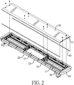
Fig. 2 is an exploded perspective view of the detachable warning lamp inFig. 1 ; -
Fig. 3 is an enlarged exploded perspective view of the detachable warning lamp inFig. 2 ; -
Fig. 4 is a perspective view of a light-emitting element of the detachable warning lamp inFig. 3 ; -
Fig. 5 is another perspective view of the light-emitting element of the detachable warning lamp inFig. 3 ; -
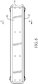
Fig. 6 is a top side view of the detachable warning lamp inFig. 1 ; -
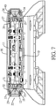
Fig. 7 is a cross sectional side view of the detachable warning lamp along line 7-7 inFig. 6 ; and -
Fig. 8 is an enlarged cross sectional side view of the detachable warning lamp inFig. 7 . - With reference to
Figs. 1 to 3 , a detachable warning lamp in accordance with the present invention comprises abase 10, a light-emittingmodule 20, and acover 30. - With reference to
Figs. 3 ,6 , and7 , thebase 10 has achamber 11, two side surfaces, a top surface, an inner bottom surface, twoside openings 12, a top opening 13, two retainingwalls 14, and twoengaging grooves 15. Thechamber 11 is formed in thebase 10. The two side surfaces of the base 10 are opposite to each other. The top surface of thebase 10 is formed across the two side surfaces of thebase 10. The inner bottom surface of thebase 10 is formed in thebase 10 and is disposed adjacent to thechamber 11 of thebase 10. - The two
side openings 12 are respectively formed through the two side surfaces of thebase 10, and are in communication with thechamber 11 of thebase 10. The top opening 13 is formed through the top surface of thebase 10 and is in communication with thechamber 11 of thebase 10. The tworetaining walls 14 are formed on the inner bottom surface of the base 10 adjacent to the twoside openings 12 of the base 10 respectively. The twoengaging grooves 15 are formed on the inner bottom surface of the base 10 adjacent to the twoside openings 12 of the base 10 respectively. Each one of the twoengaging grooves 15 is respectively located between a corresponding one of the tworetaining walls 14 of thebase 10 and a corresponding one of the twoside openings 12 of thebase 10. - With reference to
Figs. 2 and7 , the light-emittingmodule 20 is disposed on thebase 10 and has acircuit board 21 and multiple light-emittingelements 22. Thecircuit board 21 is disposed on thebase 10, and is located in thechamber 11 of thebase 10. The light-emittingelements 22 are electrically connected to thecircuit board 21 and are detachably disposed in the twoside openings 12 of thebase 10. - With reference to
Figs. 4, 5 ,7 , and8 , each one of the light-emittingelements 22 has ashell 23, a first engagingportion 24, multiple first cushioning lugs 25, a second engagingportion 26, and multiple second cushioning lugs 27. Theshell 23 has a bottom surface, a top surface, and a rear surface. The first engagingportion 24 is formed on the bottom surface of theshell 23 and is inserted into a corresponding one of the twoengaging grooves 15. The first cushioning lugs 25 are formed on and protrude out of the rear surface of theshell 23. The first cushioning lugs 25 abut a corresponding one of the tworetaining walls 14. The second engagingportion 26 is formed on the top surface of theshell 23, and is located above the first engagingportion 24. The second cushioning lugs 27 are formed on and protrude out of the rear surface of theshell 23, and are located above the first cushioning lugs 25. - With reference to
Figs. 7 and8 , thecover 30 is disposed on thebase 10, covers the top opening 13 of thebase 10, and has an inner bottom surface, twobaffles 31, and two stoppingsurfaces 32. The inner bottom surface of thecover 30 faces the inner bottom surface of thebase 10. The two baffles 31 are formed on the inner bottom surface of thecover 30 and are respectively disposed adjacent to theside openings 12 of thebase 10, and eachbaffle 31 abuts the second cushioning lugs 27 of a corresponding one of the light-emittingelements 22. The two stoppingsurfaces 32 are formed on the inner bottom surface of thecover 30 and respectively face the twobaffles 31, and each stoppingsurface 32 abuts the second engagingportion 26 of a corresponding one of the light-emittingelements 22. - With reference to
Figs. 7 and8 , thebase 10 has two first leak-proof grooves 16. The two first leak-proof grooves 16 are formed on the inner bottom surface of thebase 10, and are located between the twoengaging grooves 15 and the twoside openings 12 of thebase 10. Thecover 30 has two second leak-proof grooves 33. The two second leak-proof grooves 33 are formed on the inner bottom surface of thecover 30, and are located between the two stoppingsurfaces 32 of thecover 30 and the twoside openings 12 of thebase 10. Furthermore, the detachable warning lamp has fourwaterproof strips 40. The fourwaterproof strips 40 are respectively disposed on the two first leak-proof grooves 16 of thebase 10 and the two second leak-proof grooves 33 of thecover 30. - With reference to
Figs. 4 and 5 , each one of the light-emittingelements 22 has multiplefirst deforming spaces 28 and multiplesecond deforming spaces 29. Thefirst deforming spaces 28 are respectively formed between the first cushioning lugs 25 and the rear surface of theshell 23. Thesecond deforming spaces 29 are respectively formed between the second cushioning lugs 27 and the rear surface of theshell 23. - In assembly, the light-emitting
elements 22 are detachably engaged with the base 10 one by one, and then thecover 30 is disposed on thebase 10. The light-emittingelements 22 are disposed between the base 10 and thecover 30 for fixing the light-emittingelements 22. In each one of the light-emittingelements 22, the first cushioning lugs 25 abut theretaining walls 14 of thebase 10. Each one of the light-emittingelements 22 is pushed by the users. Each one of the first cushioning lugs 25 is deformed and provides a restoring force. The first engagingportion 24 is inserted into the corresponding one of the twoengaging grooves 15. Each one of the light-emittingelements 22 is moved out of the base 10 by the restoring force. The light-emittingelements 22 are engaged with and retained on thebase 10. Thecover 30 is disposed on thebase 10 and covers the light-emittingelements 22. The second cushioning lugs 27 of the light-emittingelements 22 abut thebaffles 31 of thecover 30. The secondengaging portions 26 of the light-emittingelements 22 abut the stoppingsurfaces 32 of thecover 30. The light-emittingelements 22 firmly abut and are retained below thecover 30. - For disassembly, the
cover 30 is detached from the base 10 by the users. The light-emittingelements 22 are detached from the base 10 by the users without a hand tool. Each one of the light-emittingelements 22 is pushed by a hand of the users and is moved. The first cushioning lugs 25 of each one of the light-emittingelements 22 are deformed. The first engagingportion 24 of each one of the light-emittingelements 22 moves out of the corresponding one of the engaginggrooves 15. Each one of the light-emittingelements 22 is lifted and is detached from the base 10 manually by the users. - Accordingly, the retaining
walls 14 and the engaginggrooves 15 are formed on thebase 10. The first engagingportion 24 and the first cushioning lugs 25 are formed on each one of the light-emittingelements 22. The light-emittingelements 22 are easy to assemble and detach without the use of a screw and the hand tool. The assembly and the disassembly of the detachable warning lamp are convenient and quick, saving time for assembly and disassembly. - In addition, the
waterproof strips 40 prevent the mist or a foreign object from going into thechamber 11 of thebase 10. Furthermore, the first cushioning lugs 25 and the second cushioning lugs 27 can be deformed in assembly and provide the restoring force for increasing the assembly stability of the detachable warning lamp.
Claims (3)
- A detachable warning lamp comprising:a base (10) havinga chamber (11) formed in the base (10);two side surfaces being opposite to each other;a top surface formed across the two side surfaces of the base (10);an inner bottom surface formed in the base (10) and disposed adjacent to the chamber (11);two side openings (12) respectively formed through the two side surfaces of the base (10) and communicating with the chamber (11) of the base (10);a top opening (13) formed through the top surface of the base (10) and communicating with the chamber (11) of the base (10);two retaining walls (14) formed on the inner bottom surface of the base (10) adjacent to the two side openings (12) of the base (10) respectively; andtwo engaging grooves (15) formed on the inner bottom surface of the base (10) adjacent to the two side openings (12) of the base (10) respectively, and each one of the two engaging grooves (15) respectively located between a corresponding one of the two retaining walls (14) and a corresponding one of the two side openings (12) of the base (10);a light-emitting module (20) disposed on the base (10), and having
a circuit board (21) disposed on the base (10) and located in the chamber (11) of the base (10); andmultiple light-emitting elements (22) electrically connected to the circuit board (21) and detachably disposed in the two side openings (12) of the base (10), and each one of the light-emitting elements (22) havinga shell (23) having a bottom surface, a top surface, and a rear surface;a first engaging portion (24) formed on the bottom surface of the shell (23) and inserted into a corresponding one of the two engaging grooves (15);multiple first cushioning lugs (25) formed on and protruding out of the rear surface of the shell (23), and abutting a corresponding one of the two retaining walls (14);a second engaging portion (26) formed on the top surface of the shell (23) and located above the first engaging portion (24); andmultiple second cushioning lugs (27) formed on and protruding out of the rear surface of the shell (23), and located above the first cushioning lugs (25); anda cover (30) disposed on the base (10), covering the top opening (13) of the base (10), and havingan inner bottom surface facing the inner bottom surface of the base (10);two baffles (31) formed on the inner bottom surface of the cover (30) and respectively disposed adjacent to the side openings (12) of the base (10), and each baffle (31) abutting the second cushioning lugs (27) of a corresponding one of the light-emitting elements (22); andtwo stopping surfaces (32) formed on the inner bottom surface of the cover (30) and respectively facing the two baffles (31), and each stopping surface abutting the second engaging portion (26) of a corresponding one of the light-emitting elements (22). - The detachable warning lamp as claimed in claim 1, wherein
the base (10) has two first leak-proof grooves (16) formed on the inner bottom surface of the base (10) and located between the two engaging grooves (15) and the two side openings (12) of the base (10);
the cover (30) has two second leak-proof grooves (33) formed on the inner bottom surface of the cover (30) and located between the two stopping surfaces (32) of the cover (30) and the two side openings (12) of the base (10); and
the detachable warning lamp has four waterproof strips (40) respectively disposed on the two first leak-proof grooves (16) of the base (10) and the two second leak-proof grooves (33) of the cover (30). - The detachable warning lamp as claimed in claims 1 or 2, wherein each one of the light-emitting elements (22) has
multiple first deforming spaces (28) respectively formed between the first cushioning lugs (25) and the rear surface of the shell (23); and
multiple second deforming spaces (29) respectively formed between the second cushioning lugs (27) and the rear surface of the shell (23).
Priority Applications (1)
| Application Number | Priority Date | Filing Date | Title |
|---|---|---|---|
| EP17197984.2A EP3477194B1 (en) | 2017-10-24 | 2017-10-24 | Detachable warning lamp |
Applications Claiming Priority (1)
| Application Number | Priority Date | Filing Date | Title |
|---|---|---|---|
| EP17197984.2A EP3477194B1 (en) | 2017-10-24 | 2017-10-24 | Detachable warning lamp |
Publications (2)
| Publication Number | Publication Date |
|---|---|
| EP3477194A1 EP3477194A1 (en) | 2019-05-01 |
| EP3477194B1 true EP3477194B1 (en) | 2020-03-18 |
Family
ID=60182402
Family Applications (1)
| Application Number | Title | Priority Date | Filing Date |
|---|---|---|---|
| EP17197984.2A Active EP3477194B1 (en) | 2017-10-24 | 2017-10-24 | Detachable warning lamp |
Country Status (1)
| Country | Link |
|---|---|
| EP (1) | EP3477194B1 (en) |
Families Citing this family (1)
| Publication number | Priority date | Publication date | Assignee | Title |
|---|---|---|---|---|
| FR3095852A1 (en) * | 2019-05-07 | 2020-11-13 | Psa Automobiles Sa | Daytime signaling module for motor vehicles and lighting and signaling assembly comprising said module |
Family Cites Families (6)
| Publication number | Priority date | Publication date | Assignee | Title |
|---|---|---|---|---|
| US6722776B1 (en) * | 2001-12-18 | 2004-04-20 | Whelen Engineering Company, Inc. | Light bar and method of assembly therefor |
| CN201310795Y (en) * | 2008-12-15 | 2009-09-16 | 虞锋 | Lightbar |
| KR100963584B1 (en) * | 2009-09-29 | 2010-06-15 | (주)볼텍스 인터내셔널 | Emergency vehicles light assembly |
| CN102454932A (en) * | 2010-10-26 | 2012-05-16 | 宁波市鄞州赛艾富光电科技有限公司 | Ultra-thin LED (light-emitting diode) long-row alarm lamp |
| CN203240456U (en) * | 2013-05-14 | 2013-10-16 | 万年国际企业有限公司 | Opening embedded warning light device |
| CN204879940U (en) * | 2015-09-10 | 2015-12-16 | 宁波市鄞州赛艾富光电科技有限公司 | Long warning light of arranging |
-
2017
- 2017-10-24 EP EP17197984.2A patent/EP3477194B1/en active Active
Non-Patent Citations (1)
| Title |
|---|
| None * |
Also Published As
| Publication number | Publication date |
|---|---|
| EP3477194A1 (en) | 2019-05-01 |
Similar Documents
| Publication | Publication Date | Title |
|---|---|---|
| USD954668S1 (en) | Housing for a power module assembly | |
| US8218301B2 (en) | Keyboard | |
| USD856948S1 (en) | Circuit board having arrangements of light-emitting diodes | |
| EP2163817A1 (en) | Replaceable lamp adapter assembly | |
| USD674949S1 (en) | Lighting system | |
| USD890643S1 (en) | Radiator for automotive applications | |
| US20090296322A1 (en) | Case unit for storage device | |
| EP2765351B1 (en) | Recessed luminaire | |
| US20190165527A1 (en) | Conductive building block having multi-sided conductivity | |
| USD939455S1 (en) | Flat switch and a flat switch module thereof | |
| EP3477194B1 (en) | Detachable warning lamp | |
| US10030832B1 (en) | Detachable warning lamp | |
| US10251290B2 (en) | Protective case assembly for handheld device | |
| KR102287008B1 (en) | Power supply apparatus for led light | |
| USD906272S1 (en) | Circuit breaker board for a portable isolation power supply | |
| CN217523061U (en) | Aluminum alloy shell with stepped side plates | |
| USD1087102S1 (en) | Dual access load mounting system | |
| USD532384S1 (en) | Light control housing | |
| CN109681832B (en) | Detachable warning lamp | |
| US8523423B2 (en) | LED mounting seat | |
| US20120113643A1 (en) | Led lamp | |
| CN204062894U (en) | Led light source board fixing structure | |
| CN209782308U (en) | Shadow-free linear LED lamp | |
| EP2072892B1 (en) | Lampshade of a light-emitting diode (LED) lamp | |
| CN207935809U (en) | A kind of LED light bar convenient for assembling |
Legal Events
| Date | Code | Title | Description |
|---|---|---|---|
| PUAI | Public reference made under article 153(3) epc to a published international application that has entered the european phase |
Free format text: ORIGINAL CODE: 0009012 |
|
| STAA | Information on the status of an ep patent application or granted ep patent |
Free format text: STATUS: REQUEST FOR EXAMINATION WAS MADE |
|
| 17P | Request for examination filed |
Effective date: 20180716 |
|
| AK | Designated contracting states |
Kind code of ref document: A1 Designated state(s): AL AT BE BG CH CY CZ DE DK EE ES FI FR GB GR HR HU IE IS IT LI LT LU LV MC MK MT NL NO PL PT RO RS SE SI SK SM TR |
|
| AX | Request for extension of the european patent |
Extension state: BA ME |
|
| GRAP | Despatch of communication of intention to grant a patent |
Free format text: ORIGINAL CODE: EPIDOSNIGR1 |
|
| STAA | Information on the status of an ep patent application or granted ep patent |
Free format text: STATUS: GRANT OF PATENT IS INTENDED |
|
| INTG | Intention to grant announced |
Effective date: 20190823 |
|
| GRAS | Grant fee paid |
Free format text: ORIGINAL CODE: EPIDOSNIGR3 |
|
| GRAA | (expected) grant |
Free format text: ORIGINAL CODE: 0009210 |
|
| STAA | Information on the status of an ep patent application or granted ep patent |
Free format text: STATUS: THE PATENT HAS BEEN GRANTED |
|
| AK | Designated contracting states |
Kind code of ref document: B1 Designated state(s): AL AT BE BG CH CY CZ DE DK EE ES FI FR GB GR HR HU IE IS IT LI LT LU LV MC MK MT NL NO PL PT RO RS SE SI SK SM TR |
|
| REG | Reference to a national code |
Ref country code: GB Ref legal event code: FG4D |
|
| REG | Reference to a national code |
Ref country code: DE Ref legal event code: R096 Ref document number: 602017013191 Country of ref document: DE |
|
| REG | Reference to a national code |
Ref country code: AT Ref legal event code: REF Ref document number: 1246308 Country of ref document: AT Kind code of ref document: T Effective date: 20200415 Ref country code: IE Ref legal event code: FG4D |
|
| PG25 | Lapsed in a contracting state [announced via postgrant information from national office to epo] |
Ref country code: NO Free format text: LAPSE BECAUSE OF FAILURE TO SUBMIT A TRANSLATION OF THE DESCRIPTION OR TO PAY THE FEE WITHIN THE PRESCRIBED TIME-LIMIT Effective date: 20200618 Ref country code: FI Free format text: LAPSE BECAUSE OF FAILURE TO SUBMIT A TRANSLATION OF THE DESCRIPTION OR TO PAY THE FEE WITHIN THE PRESCRIBED TIME-LIMIT Effective date: 20200318 Ref country code: RS Free format text: LAPSE BECAUSE OF FAILURE TO SUBMIT A TRANSLATION OF THE DESCRIPTION OR TO PAY THE FEE WITHIN THE PRESCRIBED TIME-LIMIT Effective date: 20200318 |
|
| REG | Reference to a national code |
Ref country code: NL Ref legal event code: MP Effective date: 20200318 |
|
| PG25 | Lapsed in a contracting state [announced via postgrant information from national office to epo] |
Ref country code: BG Free format text: LAPSE BECAUSE OF FAILURE TO SUBMIT A TRANSLATION OF THE DESCRIPTION OR TO PAY THE FEE WITHIN THE PRESCRIBED TIME-LIMIT Effective date: 20200618 Ref country code: GR Free format text: LAPSE BECAUSE OF FAILURE TO SUBMIT A TRANSLATION OF THE DESCRIPTION OR TO PAY THE FEE WITHIN THE PRESCRIBED TIME-LIMIT Effective date: 20200619 Ref country code: LV Free format text: LAPSE BECAUSE OF FAILURE TO SUBMIT A TRANSLATION OF THE DESCRIPTION OR TO PAY THE FEE WITHIN THE PRESCRIBED TIME-LIMIT Effective date: 20200318 Ref country code: SE Free format text: LAPSE BECAUSE OF FAILURE TO SUBMIT A TRANSLATION OF THE DESCRIPTION OR TO PAY THE FEE WITHIN THE PRESCRIBED TIME-LIMIT Effective date: 20200318 Ref country code: HR Free format text: LAPSE BECAUSE OF FAILURE TO SUBMIT A TRANSLATION OF THE DESCRIPTION OR TO PAY THE FEE WITHIN THE PRESCRIBED TIME-LIMIT Effective date: 20200318 |
|
| REG | Reference to a national code |
Ref country code: LT Ref legal event code: MG4D |
|
| PG25 | Lapsed in a contracting state [announced via postgrant information from national office to epo] |
Ref country code: NL Free format text: LAPSE BECAUSE OF FAILURE TO SUBMIT A TRANSLATION OF THE DESCRIPTION OR TO PAY THE FEE WITHIN THE PRESCRIBED TIME-LIMIT Effective date: 20200318 |
|
| PG25 | Lapsed in a contracting state [announced via postgrant information from national office to epo] |
Ref country code: PT Free format text: LAPSE BECAUSE OF FAILURE TO SUBMIT A TRANSLATION OF THE DESCRIPTION OR TO PAY THE FEE WITHIN THE PRESCRIBED TIME-LIMIT Effective date: 20200812 Ref country code: LT Free format text: LAPSE BECAUSE OF FAILURE TO SUBMIT A TRANSLATION OF THE DESCRIPTION OR TO PAY THE FEE WITHIN THE PRESCRIBED TIME-LIMIT Effective date: 20200318 Ref country code: IS Free format text: LAPSE BECAUSE OF FAILURE TO SUBMIT A TRANSLATION OF THE DESCRIPTION OR TO PAY THE FEE WITHIN THE PRESCRIBED TIME-LIMIT Effective date: 20200718 Ref country code: RO Free format text: LAPSE BECAUSE OF FAILURE TO SUBMIT A TRANSLATION OF THE DESCRIPTION OR TO PAY THE FEE WITHIN THE PRESCRIBED TIME-LIMIT Effective date: 20200318 Ref country code: CZ Free format text: LAPSE BECAUSE OF FAILURE TO SUBMIT A TRANSLATION OF THE DESCRIPTION OR TO PAY THE FEE WITHIN THE PRESCRIBED TIME-LIMIT Effective date: 20200318 Ref country code: SK Free format text: LAPSE BECAUSE OF FAILURE TO SUBMIT A TRANSLATION OF THE DESCRIPTION OR TO PAY THE FEE WITHIN THE PRESCRIBED TIME-LIMIT Effective date: 20200318 Ref country code: SM Free format text: LAPSE BECAUSE OF FAILURE TO SUBMIT A TRANSLATION OF THE DESCRIPTION OR TO PAY THE FEE WITHIN THE PRESCRIBED TIME-LIMIT Effective date: 20200318 Ref country code: EE Free format text: LAPSE BECAUSE OF FAILURE TO SUBMIT A TRANSLATION OF THE DESCRIPTION OR TO PAY THE FEE WITHIN THE PRESCRIBED TIME-LIMIT Effective date: 20200318 |
|
| REG | Reference to a national code |
Ref country code: AT Ref legal event code: MK05 Ref document number: 1246308 Country of ref document: AT Kind code of ref document: T Effective date: 20200318 |
|
| REG | Reference to a national code |
Ref country code: DE Ref legal event code: R097 Ref document number: 602017013191 Country of ref document: DE |
|
| PLBE | No opposition filed within time limit |
Free format text: ORIGINAL CODE: 0009261 |
|
| STAA | Information on the status of an ep patent application or granted ep patent |
Free format text: STATUS: NO OPPOSITION FILED WITHIN TIME LIMIT |
|
| PG25 | Lapsed in a contracting state [announced via postgrant information from national office to epo] |
Ref country code: ES Free format text: LAPSE BECAUSE OF FAILURE TO SUBMIT A TRANSLATION OF THE DESCRIPTION OR TO PAY THE FEE WITHIN THE PRESCRIBED TIME-LIMIT Effective date: 20200318 Ref country code: AT Free format text: LAPSE BECAUSE OF FAILURE TO SUBMIT A TRANSLATION OF THE DESCRIPTION OR TO PAY THE FEE WITHIN THE PRESCRIBED TIME-LIMIT Effective date: 20200318 Ref country code: DK Free format text: LAPSE BECAUSE OF FAILURE TO SUBMIT A TRANSLATION OF THE DESCRIPTION OR TO PAY THE FEE WITHIN THE PRESCRIBED TIME-LIMIT Effective date: 20200318 Ref country code: IT Free format text: LAPSE BECAUSE OF FAILURE TO SUBMIT A TRANSLATION OF THE DESCRIPTION OR TO PAY THE FEE WITHIN THE PRESCRIBED TIME-LIMIT Effective date: 20200318 |
|
| 26N | No opposition filed |
Effective date: 20201221 |
|
| PG25 | Lapsed in a contracting state [announced via postgrant information from national office to epo] |
Ref country code: PL Free format text: LAPSE BECAUSE OF FAILURE TO SUBMIT A TRANSLATION OF THE DESCRIPTION OR TO PAY THE FEE WITHIN THE PRESCRIBED TIME-LIMIT Effective date: 20200318 |
|
| PG25 | Lapsed in a contracting state [announced via postgrant information from national office to epo] |
Ref country code: SI Free format text: LAPSE BECAUSE OF FAILURE TO SUBMIT A TRANSLATION OF THE DESCRIPTION OR TO PAY THE FEE WITHIN THE PRESCRIBED TIME-LIMIT Effective date: 20200318 |
|
| REG | Reference to a national code |
Ref country code: CH Ref legal event code: PL |
|
| PG25 | Lapsed in a contracting state [announced via postgrant information from national office to epo] |
Ref country code: MC Free format text: LAPSE BECAUSE OF FAILURE TO SUBMIT A TRANSLATION OF THE DESCRIPTION OR TO PAY THE FEE WITHIN THE PRESCRIBED TIME-LIMIT Effective date: 20200318 Ref country code: LU Free format text: LAPSE BECAUSE OF NON-PAYMENT OF DUE FEES Effective date: 20201024 |
|
| REG | Reference to a national code |
Ref country code: BE Ref legal event code: MM Effective date: 20201031 |
|
| PG25 | Lapsed in a contracting state [announced via postgrant information from national office to epo] |
Ref country code: LI Free format text: LAPSE BECAUSE OF NON-PAYMENT OF DUE FEES Effective date: 20201031 Ref country code: CH Free format text: LAPSE BECAUSE OF NON-PAYMENT OF DUE FEES Effective date: 20201031 Ref country code: BE Free format text: LAPSE BECAUSE OF NON-PAYMENT OF DUE FEES Effective date: 20201031 |
|
| PG25 | Lapsed in a contracting state [announced via postgrant information from national office to epo] |
Ref country code: IE Free format text: LAPSE BECAUSE OF NON-PAYMENT OF DUE FEES Effective date: 20201024 |
|
| PGFP | Annual fee paid to national office [announced via postgrant information from national office to epo] |
Ref country code: FR Payment date: 20210823 Year of fee payment: 5 |
|
| PGFP | Annual fee paid to national office [announced via postgrant information from national office to epo] |
Ref country code: GB Payment date: 20210818 Year of fee payment: 5 |
|
| PGFP | Annual fee paid to national office [announced via postgrant information from national office to epo] |
Ref country code: DE Payment date: 20210923 Year of fee payment: 5 |
|
| PG25 | Lapsed in a contracting state [announced via postgrant information from national office to epo] |
Ref country code: TR Free format text: LAPSE BECAUSE OF FAILURE TO SUBMIT A TRANSLATION OF THE DESCRIPTION OR TO PAY THE FEE WITHIN THE PRESCRIBED TIME-LIMIT Effective date: 20200318 Ref country code: MT Free format text: LAPSE BECAUSE OF FAILURE TO SUBMIT A TRANSLATION OF THE DESCRIPTION OR TO PAY THE FEE WITHIN THE PRESCRIBED TIME-LIMIT Effective date: 20200318 Ref country code: CY Free format text: LAPSE BECAUSE OF FAILURE TO SUBMIT A TRANSLATION OF THE DESCRIPTION OR TO PAY THE FEE WITHIN THE PRESCRIBED TIME-LIMIT Effective date: 20200318 |
|
| PG25 | Lapsed in a contracting state [announced via postgrant information from national office to epo] |
Ref country code: MK Free format text: LAPSE BECAUSE OF FAILURE TO SUBMIT A TRANSLATION OF THE DESCRIPTION OR TO PAY THE FEE WITHIN THE PRESCRIBED TIME-LIMIT Effective date: 20200318 Ref country code: AL Free format text: LAPSE BECAUSE OF FAILURE TO SUBMIT A TRANSLATION OF THE DESCRIPTION OR TO PAY THE FEE WITHIN THE PRESCRIBED TIME-LIMIT Effective date: 20200318 |
|
| REG | Reference to a national code |
Ref country code: DE Ref legal event code: R119 Ref document number: 602017013191 Country of ref document: DE |
|
| GBPC | Gb: european patent ceased through non-payment of renewal fee |
Effective date: 20221024 |
|
| PG25 | Lapsed in a contracting state [announced via postgrant information from national office to epo] |
Ref country code: FR Free format text: LAPSE BECAUSE OF NON-PAYMENT OF DUE FEES Effective date: 20221031 Ref country code: DE Free format text: LAPSE BECAUSE OF NON-PAYMENT OF DUE FEES Effective date: 20230503 |
|
| PG25 | Lapsed in a contracting state [announced via postgrant information from national office to epo] |
Ref country code: GB Free format text: LAPSE BECAUSE OF NON-PAYMENT OF DUE FEES Effective date: 20221024 |