EP3477179A1 - A subsea cable system and a method for supplying electrical power to a subsea device - Google Patents
A subsea cable system and a method for supplying electrical power to a subsea device Download PDFInfo
- Publication number
- EP3477179A1 EP3477179A1 EP17306498.1A EP17306498A EP3477179A1 EP 3477179 A1 EP3477179 A1 EP 3477179A1 EP 17306498 A EP17306498 A EP 17306498A EP 3477179 A1 EP3477179 A1 EP 3477179A1
- Authority
- EP
- European Patent Office
- Prior art keywords
- cable
- subsea
- conductor
- leg
- supply
- Prior art date
- Legal status (The legal status is an assumption and is not a legal conclusion. Google has not performed a legal analysis and makes no representation as to the accuracy of the status listed.)
- Granted
Links
- 238000000034 method Methods 0.000 title claims abstract description 16
- 239000004020 conductor Substances 0.000 claims abstract description 199
- 230000007704 transition Effects 0.000 claims abstract description 81
- 230000005611 electricity Effects 0.000 claims abstract description 5
- 238000009413 insulation Methods 0.000 claims description 42
- 239000004065 semiconductor Substances 0.000 claims description 18
- 229920003020 cross-linked polyethylene Polymers 0.000 claims description 11
- 239000004703 cross-linked polyethylene Substances 0.000 claims description 11
- 238000010438 heat treatment Methods 0.000 claims description 10
- 230000006835 compression Effects 0.000 claims description 6
- 238000007906 compression Methods 0.000 claims description 6
- 229920000181 Ethylene propylene rubber Polymers 0.000 description 14
- 239000000945 filler Substances 0.000 description 12
- 239000000463 material Substances 0.000 description 10
- 230000003068 static effect Effects 0.000 description 8
- XLYOFNOQVPJJNP-UHFFFAOYSA-N water Substances O XLYOFNOQVPJJNP-UHFFFAOYSA-N 0.000 description 7
- 239000004698 Polyethylene Substances 0.000 description 6
- 238000005452 bending Methods 0.000 description 6
- 229920000573 polyethylene Polymers 0.000 description 6
- 241001071864 Lethrinus laticaudis Species 0.000 description 5
- 230000015572 biosynthetic process Effects 0.000 description 5
- 229930195733 hydrocarbon Natural products 0.000 description 5
- 150000002430 hydrocarbons Chemical class 0.000 description 5
- 238000004519 manufacturing process Methods 0.000 description 5
- -1 polyethylene Polymers 0.000 description 5
- 238000005485 electric heating Methods 0.000 description 4
- 239000000835 fiber Substances 0.000 description 4
- 239000003643 water by type Substances 0.000 description 4
- 238000005553 drilling Methods 0.000 description 3
- 239000012530 fluid Substances 0.000 description 3
- 150000004677 hydrates Chemical class 0.000 description 3
- ORQBXQOJMQIAOY-UHFFFAOYSA-N nobelium Chemical compound [No] ORQBXQOJMQIAOY-UHFFFAOYSA-N 0.000 description 3
- 239000006229 carbon black Substances 0.000 description 2
- 230000007797 corrosion Effects 0.000 description 2
- 238000005260 corrosion Methods 0.000 description 2
- 230000003287 optical effect Effects 0.000 description 2
- 239000003351 stiffener Substances 0.000 description 2
- 239000011800 void material Substances 0.000 description 2
- 229910000838 Al alloy Inorganic materials 0.000 description 1
- RYGMFSIKBFXOCR-UHFFFAOYSA-N Copper Chemical compound [Cu] RYGMFSIKBFXOCR-UHFFFAOYSA-N 0.000 description 1
- 229910000881 Cu alloy Inorganic materials 0.000 description 1
- 229910001335 Galvanized steel Inorganic materials 0.000 description 1
- 239000004743 Polypropylene Substances 0.000 description 1
- 239000004411 aluminium Substances 0.000 description 1
- XAGFODPZIPBFFR-UHFFFAOYSA-N aluminium Chemical compound [Al] XAGFODPZIPBFFR-UHFFFAOYSA-N 0.000 description 1
- 229910052782 aluminium Inorganic materials 0.000 description 1
- 239000010949 copper Substances 0.000 description 1
- 229910052802 copper Inorganic materials 0.000 description 1
- 230000001419 dependent effect Effects 0.000 description 1
- 239000008397 galvanized steel Substances 0.000 description 1
- 238000009434 installation Methods 0.000 description 1
- 239000011810 insulating material Substances 0.000 description 1
- 238000005304 joining Methods 0.000 description 1
- 238000012986 modification Methods 0.000 description 1
- 230000004048 modification Effects 0.000 description 1
- 229920001155 polypropylene Polymers 0.000 description 1
- 239000013535 sea water Substances 0.000 description 1
- 238000003860 storage Methods 0.000 description 1
- 239000000126 substance Substances 0.000 description 1
Images


Classifications
-
- H—ELECTRICITY
- H01—ELECTRIC ELEMENTS
- H01B—CABLES; CONDUCTORS; INSULATORS; SELECTION OF MATERIALS FOR THEIR CONDUCTIVE, INSULATING OR DIELECTRIC PROPERTIES
- H01B9/00—Power cables
- H01B9/006—Constructional features relating to the conductors
-
- F—MECHANICAL ENGINEERING; LIGHTING; HEATING; WEAPONS; BLASTING
- F16—ENGINEERING ELEMENTS AND UNITS; GENERAL MEASURES FOR PRODUCING AND MAINTAINING EFFECTIVE FUNCTIONING OF MACHINES OR INSTALLATIONS; THERMAL INSULATION IN GENERAL
- F16L—PIPES; JOINTS OR FITTINGS FOR PIPES; SUPPORTS FOR PIPES, CABLES OR PROTECTIVE TUBING; MEANS FOR THERMAL INSULATION IN GENERAL
- F16L53/00—Heating of pipes or pipe systems; Cooling of pipes or pipe systems
- F16L53/30—Heating of pipes or pipe systems
- F16L53/35—Ohmic-resistance heating
- F16L53/37—Ohmic-resistance heating the heating current flowing directly through the pipe to be heated
-
- F—MECHANICAL ENGINEERING; LIGHTING; HEATING; WEAPONS; BLASTING
- F16—ENGINEERING ELEMENTS AND UNITS; GENERAL MEASURES FOR PRODUCING AND MAINTAINING EFFECTIVE FUNCTIONING OF MACHINES OR INSTALLATIONS; THERMAL INSULATION IN GENERAL
- F16L—PIPES; JOINTS OR FITTINGS FOR PIPES; SUPPORTS FOR PIPES, CABLES OR PROTECTIVE TUBING; MEANS FOR THERMAL INSULATION IN GENERAL
- F16L1/00—Laying or reclaiming pipes; Repairing or joining pipes on or under water
- F16L1/12—Laying or reclaiming pipes on or under water
- F16L1/14—Laying or reclaiming pipes on or under water between the surface and the bottom
- F16L1/15—Laying or reclaiming pipes on or under water between the surface and the bottom vertically
-
- F—MECHANICAL ENGINEERING; LIGHTING; HEATING; WEAPONS; BLASTING
- F16—ENGINEERING ELEMENTS AND UNITS; GENERAL MEASURES FOR PRODUCING AND MAINTAINING EFFECTIVE FUNCTIONING OF MACHINES OR INSTALLATIONS; THERMAL INSULATION IN GENERAL
- F16L—PIPES; JOINTS OR FITTINGS FOR PIPES; SUPPORTS FOR PIPES, CABLES OR PROTECTIVE TUBING; MEANS FOR THERMAL INSULATION IN GENERAL
- F16L53/00—Heating of pipes or pipe systems; Cooling of pipes or pipe systems
- F16L53/30—Heating of pipes or pipe systems
- F16L53/35—Ohmic-resistance heating
- F16L53/38—Ohmic-resistance heating using elongate electric heating elements, e.g. wires or ribbons
-
- H—ELECTRICITY
- H01—ELECTRIC ELEMENTS
- H01B—CABLES; CONDUCTORS; INSULATORS; SELECTION OF MATERIALS FOR THEIR CONDUCTIVE, INSULATING OR DIELECTRIC PROPERTIES
- H01B3/00—Insulators or insulating bodies characterised by the insulating materials; Selection of materials for their insulating or dielectric properties
- H01B3/18—Insulators or insulating bodies characterised by the insulating materials; Selection of materials for their insulating or dielectric properties mainly consisting of organic substances
- H01B3/30—Insulators or insulating bodies characterised by the insulating materials; Selection of materials for their insulating or dielectric properties mainly consisting of organic substances plastics; resins; waxes
- H01B3/44—Insulators or insulating bodies characterised by the insulating materials; Selection of materials for their insulating or dielectric properties mainly consisting of organic substances plastics; resins; waxes vinyl resins; acrylic resins
- H01B3/441—Insulators or insulating bodies characterised by the insulating materials; Selection of materials for their insulating or dielectric properties mainly consisting of organic substances plastics; resins; waxes vinyl resins; acrylic resins from alkenes
-
- H—ELECTRICITY
- H01—ELECTRIC ELEMENTS
- H01B—CABLES; CONDUCTORS; INSULATORS; SELECTION OF MATERIALS FOR THEIR CONDUCTIVE, INSULATING OR DIELECTRIC PROPERTIES
- H01B7/00—Insulated conductors or cables characterised by their form
- H01B7/02—Disposition of insulation
- H01B7/0208—Cables with several layers of insulating material
- H01B7/0216—Two layers
-
- H—ELECTRICITY
- H01—ELECTRIC ELEMENTS
- H01B—CABLES; CONDUCTORS; INSULATORS; SELECTION OF MATERIALS FOR THEIR CONDUCTIVE, INSULATING OR DIELECTRIC PROPERTIES
- H01B7/00—Insulated conductors or cables characterised by their form
- H01B7/14—Submarine cables
-
- H—ELECTRICITY
- H01—ELECTRIC ELEMENTS
- H01R—ELECTRICALLY-CONDUCTIVE CONNECTIONS; STRUCTURAL ASSOCIATIONS OF A PLURALITY OF MUTUALLY-INSULATED ELECTRICAL CONNECTING ELEMENTS; COUPLING DEVICES; CURRENT COLLECTORS
- H01R11/00—Individual connecting elements providing two or more spaced connecting locations for conductive members which are, or may be, thereby interconnected, e.g. end pieces for wires or cables supported by the wire or cable and having means for facilitating electrical connection to some other wire, terminal, or conductive member, blocks of binding posts
- H01R11/01—Individual connecting elements providing two or more spaced connecting locations for conductive members which are, or may be, thereby interconnected, e.g. end pieces for wires or cables supported by the wire or cable and having means for facilitating electrical connection to some other wire, terminal, or conductive member, blocks of binding posts characterised by the form or arrangement of the conductive interconnection between the connecting locations
-
- H—ELECTRICITY
- H01—ELECTRIC ELEMENTS
- H01R—ELECTRICALLY-CONDUCTIVE CONNECTIONS; STRUCTURAL ASSOCIATIONS OF A PLURALITY OF MUTUALLY-INSULATED ELECTRICAL CONNECTING ELEMENTS; COUPLING DEVICES; CURRENT COLLECTORS
- H01R11/00—Individual connecting elements providing two or more spaced connecting locations for conductive members which are, or may be, thereby interconnected, e.g. end pieces for wires or cables supported by the wire or cable and having means for facilitating electrical connection to some other wire, terminal, or conductive member, blocks of binding posts
- H01R11/03—Individual connecting elements providing two or more spaced connecting locations for conductive members which are, or may be, thereby interconnected, e.g. end pieces for wires or cables supported by the wire or cable and having means for facilitating electrical connection to some other wire, terminal, or conductive member, blocks of binding posts characterised by the relationship between the connecting locations
- H01R11/09—Individual connecting elements providing two or more spaced connecting locations for conductive members which are, or may be, thereby interconnected, e.g. end pieces for wires or cables supported by the wire or cable and having means for facilitating electrical connection to some other wire, terminal, or conductive member, blocks of binding posts characterised by the relationship between the connecting locations the connecting locations being identical
-
- H—ELECTRICITY
- H01—ELECTRIC ELEMENTS
- H01R—ELECTRICALLY-CONDUCTIVE CONNECTIONS; STRUCTURAL ASSOCIATIONS OF A PLURALITY OF MUTUALLY-INSULATED ELECTRICAL CONNECTING ELEMENTS; COUPLING DEVICES; CURRENT COLLECTORS
- H01R11/00—Individual connecting elements providing two or more spaced connecting locations for conductive members which are, or may be, thereby interconnected, e.g. end pieces for wires or cables supported by the wire or cable and having means for facilitating electrical connection to some other wire, terminal, or conductive member, blocks of binding posts
- H01R11/11—End pieces or tapping pieces for wires, supported by the wire and for facilitating electrical connection to some other wire, terminal or conductive member
- H01R11/28—End pieces consisting of a ferrule or sleeve
-
- H—ELECTRICITY
- H01—ELECTRIC ELEMENTS
- H01R—ELECTRICALLY-CONDUCTIVE CONNECTIONS; STRUCTURAL ASSOCIATIONS OF A PLURALITY OF MUTUALLY-INSULATED ELECTRICAL CONNECTING ELEMENTS; COUPLING DEVICES; CURRENT COLLECTORS
- H01R11/00—Individual connecting elements providing two or more spaced connecting locations for conductive members which are, or may be, thereby interconnected, e.g. end pieces for wires or cables supported by the wire or cable and having means for facilitating electrical connection to some other wire, terminal, or conductive member, blocks of binding posts
- H01R11/11—End pieces or tapping pieces for wires, supported by the wire and for facilitating electrical connection to some other wire, terminal or conductive member
- H01R11/32—End pieces with two or more terminations
-
- H—ELECTRICITY
- H02—GENERATION; CONVERSION OR DISTRIBUTION OF ELECTRIC POWER
- H02G—INSTALLATION OF ELECTRIC CABLES OR LINES, OR OF COMBINED OPTICAL AND ELECTRIC CABLES OR LINES
- H02G9/00—Installations of electric cables or lines in or on the ground or water
- H02G9/12—Installations of electric cables or lines in or on the ground or water supported on or from floats, e.g. in water
-
- E—FIXED CONSTRUCTIONS
- E21—EARTH OR ROCK DRILLING; MINING
- E21B—EARTH OR ROCK DRILLING; OBTAINING OIL, GAS, WATER, SOLUBLE OR MELTABLE MATERIALS OR A SLURRY OF MINERALS FROM WELLS
- E21B41/00—Equipment or details not covered by groups E21B15/00 - E21B40/00
- E21B41/0007—Equipment or details not covered by groups E21B15/00 - E21B40/00 for underwater installations
Definitions
- the present invention relates to a subsea cable system and a method for supplying electrical power to a subsea consumer device of electricity for MV (medium voltage) and HV (high voltage) applications subsea.
- the cable system may be used for transfer of electric power from the top side of a floating structure to a subsea device or structure that consumes electrical power.
- electrical power may be supplied to one end of the pipeline or the end of the section of the pipeline being heated, usually through a piggy back cable arranged on the pipeline or the section of the pipeline being heated, then using the pipeline itself as a resistive heating element to provide the heat energy needed to keep the temperature of the fluids in the pipeline above the temperatures where there is a risk for wax and hydrate formation.
- a coaxial subsea cable is commonly provided where the subsea cable is connected to a source of electrical energy on the topside structure that is typically a platform, an FPSO (Floating Production, Storage and Offloading) unit or a similar structure.
- FPSO Floating Production, Storage and Offloading
- a coaxial cable the conductor conducting the electric current from the topside structure down to the subsea devices and the conductor conducting the electric current back to the topside structure are arranged coaxially within the subsea cable.
- a challenge with such subsea power cables in deep waters and ultradeep waters is the high topside tension that is caused by the weight of the subsea cable itself and thereby the risk of overloading the conductors of the subsea cable.
- An object of the present invention is therefore to provide a subsea cable system that is capable of supplying electric power to a subsea consumer device arranged at a large or ultra large depth.
- a further objective is to provide electric power to heat a subsea pipeline by direct electric heating where the pipeline is located at a large or ultra large depth.
- the subsea cable system for transfer of electric power to a subsea device.
- the subsea cable system comprises a subsea cable, for example a subsea riser cable, with a first end portion and a second end portion where the first end portion is adapted for connection to a supply of electrical energy.
- the subsea cable comprises at least a first supply cable, a second supply cable and at least one return cable.
- the first supply cable, the second supply cable and the at least one return cable each comprises a conductor element for conduction of an electric current.
- the subsea cable system further comprises a conductor transition element comprising a conductor element that is provided with at least a first conductor leg, a second conductor leg and a third conductor leg where the first conductor leg is connected to the conductor element of the first supply cable, the second conductor leg is connected to the conductor element of the second supply cable and the third conductor leg is connectable to a subsea consumer device.
- a conductor transition element comprising a conductor element that is provided with at least a first conductor leg, a second conductor leg and a third conductor leg where the first conductor leg is connected to the conductor element of the first supply cable, the second conductor leg is connected to the conductor element of the second supply cable and the third conductor leg is connectable to a subsea consumer device.
- the first supply cable and the second supply cable are thereby combined into a single end supply cable that provides electrical power to the subsea consumer device.
- the third conductor leg of the conductor transition element may be connected to the subsea consumer device in various ways.
- the third conductor leg of the conductor transition element may be directly connected to the subsea consumer device.
- the third conductor leg of the conductor transition element may be connected to a conductor element of an end supply cable that is further connected to the subsea consumer device.
- the claimed invention therefore solves the problems mentioned above by employing a subsea cable that does not comprise coaxially arranged electrical conductors. Instead, the subsea cable is provided with two or more separate conductors, i.e.
- the conductors of the supply cables that conduct the electrical current from a source of electrical power, usually arranged on a topside structure such as a platform or an FPSO-unit, down to a subsea consumer of electrical energy, and at least one, but preferably two or more separate conductors, i.e. the conductor of the at least one return cable, that conduct the electrical current back to the topside structure.
- the claimed invention includes a conductor transition element that will merge the plurality of supply cables/conductors into a single conductor before the electrical current is supplied to the subsea consumer device, for example a pipeline or a section of a pipeline that needs to be heated, where the electrical current is possibly carried to a second end portion of the pipeline or the section of the pipeline to be heated through a piggy back cable.
- the conductor transition element that combines the two phases of the electrical supply current may be given different types of shapes, but preferably the conductor transition element is generally Y-shaped or T-shaped.
- the conductor transition element thereby comprises a first leg that includes the first conductor leg, a second leg that includes the second conductor leg and a third leg that includes the third conductor leg.
- the conductor transition element is preferably provided with an insulation system comprising at least an inner layer, an outer layer and an insulation layer that is arranged between the inner layer and the outer layer.
- the inner layer is preferably made of a semi-conducting material.
- the semi-conducting material may be, for example, EPR (ethylene-propylene rubber).
- the insulation layer is preferably made of cured, cross linked polyethylene.
- the outer layer is preferably also made of a semi-conducting material.
- the semi-conducting material may be, for example, EPR (ethylene-propylene rubber).
- the first leg of the conductor transition element is preferably provided with a first connector device for connection of the first supply cable to the first leg.
- the second leg of the conductor transition element is preferably provided with a second connector device for connection of the second supply cable to the second leg.
- the third leg of the conductor transition element is preferably provided with a third connector device for connection of the third leg to the subsea consumer device or to an end supply cable that may further be connected to the subsea consumer device.
- the first connector device, the second connector device and the third connector device may be of different types, but in a preferred embodiment at least one, but preferably each of the first connector device, the second connector device and the third connector device comprises a compression ferrule.
- the compression ferrules of the first connector device, the second connector device and the third connector device may be adapted for mechanical and/or electrical connection of the first conductor leg of the first leg to the conductor element of the first supply cable, the second conductor leg of the second leg to the conductor element of the second supply cable and the third conductor leg of the third leg directly to the subsea consumer device or to the conductor element of the end supply cable.
- the first connector device, the second connector device and the third connector device preferably are each preferably provided with an insulation system, preferably a lapped insulation system.
- the insulation system covers the three joints that joins the three conductor legs of the conductor transition element to the conductor elements of the first supply cable, the second supply cable and the subsea consumer device or the end supply cable respectively.
- the insulation system covering the joints is preferably similar to the insulation system provided on the conductor transition element.
- the insulation system therefore, preferably comprises an inner layer of a semiconducting material, an outer layer preferably also of a semiconducting material, and an insulation layer that is arranged between the inner layer and the outer layer.
- the semiconducting material of the inner layer and the outer layer is preferably EPR (ethylene-propylene rubber), but other suitable semiconducting materials may be chosen if that is desired.
- the insulation layer is preferably made of cured, cross linked poly ethylene, although other suitable insulating materials may be chosen if that is desired.
- the subsea cable comprises at least a first return cable and may preferably also comprise a second return cable, i.e. the subsea cable comprises at least two return cables for the electric current.
- the conductor transition element is preferably attached to a support element that is attached to the pipeline.
- the support element preferably comprises a substantially flat part on which the conductor transition element is securely arranged.
- the subsea consumer device may be a pipeline and the subsea cable system may further comprise an end supply cable that is connected to the third leg of the conductor transition element and to the pipeline.
- the end supply cable is preferably a piggyback cable which is mechanically and electrically connected to the pipeline.
- the piggyback cable is preferably mechanically and electrically connected to a second end portion of the pipeline and the at least one return cable is preferably mechanically and electrically connected to a first end of the pipeline whereby the pipeline can be heated by an electric current passing through the pipeline due to resistive heat being produced in the pipeline as the electric current is passing through it.
- the subsea cable system thereby provides the necessary electric current for direct electrical heating of the pipeline.
- the first end portion of the pipeline and the second end portion of the pipeline is therefore opposite ends of the pipeline, or opposite ends of the part of the pipeline that is being heated by direct electrical heating.
- the subsea consumer device can be provided with electrical power.
- the conductors of the first supply cable and the second supply cable are thereby combined into a single conductor that is providing electrical power to a subsea consumer device when the third leg of the conductor transition element is electrically connected to the subsea consumer device.
- the third leg of the conductor transition element may be connected directly to the subsea consumer device.
- the connection of the third leg of the conductor transition element to the subsea consumer device is preferably done during the laying of the subsea cable and the subsea consumer device.
- the connection of the third leg of the conductor transition element to the subsea consumer device is done after the process of laying the subsea cable and the subsea consumer device have been carried out.
- the third leg of the conductor transition element may be connected to an end supply cable that is further connected to the subsea consumer device.
- the connection of the end supply cable to the third leg of the conductor transition element and to the subsea consumer device is preferably done during the laying of the subsea cable and the subsea consumer device.
- the connection of the end supply cable to the third leg of the conductor transition element and to the subsea consumer device is done after the process of laying the subsea cable and the subsea consumer device have been carried out.
- At least one of the steps of the present method are carried out on one or more floating vessels before and/or during the laying of the subsea cable, the conductor transition element the subsea consumer device and possibly the end supply cable if such a cable is included for connection of the subsea consumer device to the conductor transition element.
- the remaining steps of the present method that are not carried out on the at least one floating vessel, are carried out subsea, preferably at the installation site subsea, and preferably by employing one or more remote operated vehicles (ROV).
- ROV remote operated vehicles
- all steps of the present method are carried out on one or more floating vessels before and/or during the laying of the subsea cable, the conductor transition element, the subsea consumer device and possibly the end supply cable if such a cable is included for connection of the subsea consumer device to the conductor transition element, i.e. the different parts of the subsea cable system is connected to each other before it is being lowered from the at least one floating vessel into the sea.
- This method is particularly useful for installing a subsea cable system as described herein. It should also be noted that the steps of the method listed above does not have to be carried out in the order that they are listed. For example, if one or more steps are carried out subsea, the order of the steps of the method listed above may change.
- the consumer device may be a pipe or a pipeline or a section of a pipe or a pipeline and the end supply cable may typically be a piggyback cable mounted to the pipeline.
- the consumer device may also be a device other than a pipe or a pipeline such as a valve device or a subsea transformer that supplies electrical energy to other subsea devices.
- the end supply cable and the at least one return cable are preferably electrically connected to the pipe or pipeline, or the section of the pipe or pipeline, to be heated at respective opposite end portions of the pipe or pipeline.
- an end supply cable in the form of a piggyback cable may be electrically connected to a second end portion of the pipeline and the at least one return cable may be electrically connected to a first end portion of the pipeline.
- the conductor transition element is preferably mounted on a support element that is attached to the pipeline.
- the support element may be provided with a substantially flat part on which the conductor transition element is securely arranged.
- the conductor transition element is preferably a generally Y-shaped or T-shaped conductor transition element that comprises the first leg, the second leg and the third leg so that the conductor transition element can be electrically connected to the conductor elements of the first supply cable, the second supply cable and the end supply cable respectively.
- the subsea cable may, in an embodiment, be provided with a first return cable and a second return cable.
- the first return cable and the second return cable are preferably electrically connected to the subsea consumer device, for example to the pipeline if the subsea consumer device is a pipeline.
- the present subsea cable system is suitable for large water depths, typically for use in large water depths exceeding about 1000m and also for use in ultra-deep waters that exceed about 3000m.
- the subsea cable may be a subsea riser cable or any other type of suitable subsea cable.
- the present subsea cable system described herein can be used for heating of a subsea pipe or pipeline or a section of a subsea pipe or pipeline.
- the heating typically takes place through direct electrical heating of the subsea pipe or pipeline or a section of a subsea pipe or pipeline.
- subsea cable system includes supply of electrical energy to an electrical subsea transformer that supply different types of subsea equipment, such as pumps and valve devices, with electrical energy.
- the subsea cable system may also be used to supply electrical energy to heat a plurality of subsea pipes or pipelines.
- a subsea cable system 10 according to the present invention is shown in figures 1-10 where figure 1 shows the complete system.
- a subsea cable 11 is shown that is connected to a floating structure comprising a deck 84 and a subsea consumer device 46 of electrical energy.
- the subsea cable 11 may be a subsea riser cable as indicated in the figures, or any other type of suitable subsea cable.
- the subsea cable comprises a dynamic subsea cable part 12 that is arranged so that it is, for the most part, floating submerged in the water, and a static subsea cable part 17 that is, for the most part, arranged on the seabed.
- An anchor device 16 is arranged at or near the seabed comprising a support part 20 for the subsea cable 11.
- a second end portion 14 of the dynamic subsea cable part 12 and a first end portion 18 of the static subsea cable part 17 are preferably joined on the support part 20 of the anchor device 16 as indicated in figure 1 .
- the subsea cable 11 shown in the figures comprises a dynamic subsea cable part 12 and a static subsea cable part 17, the subsea cable does not have to comprise both parts.
- the subsea cable 11 may be provided with a dynamic subsea cable part 12 only that is directly connected to the subsea consumer device 46.
- the dynamic subsea cable part 12 comprises a first end portion 13, that is the same as the first end portion 26 of the subsea cable 11, that is connected to a floating structure that comprises a deck 84 or similar on which at least one, but preferably a plurality of top side junction boxes 86 are arranged.
- the first end portion 26 of the subsea cable 11 may be provided with a hang-off arrangement 87 and a first guide tube 89 for the subsea cable 11.
- a second guide tube 90 and a bending stiffener 85 attached to the second guide tube 90 is provided to avoid excessive and potentially damaging bending of the subsea cable 11.
- the dynamic subsea cable part 12 may further be provided with one or more buoyancy elements 43 as indicated in figure 1 , to obtain the desired shape of the dynamic subsea cable part 12 in the water.
- the subsea consumer device is a part of a pipeline or a pipeline 46, but the subsea consumer device may also be other types of subsea equipment such as valve devices or subsea transformer devices.
- the second end portion 27 of the subsea cable 11 may further be provided with one or more bending restrictors 44 to prevent excessive bending of the subsea cable 11 and thereby potential damage to the subsea cable 11.
- FIG 2 a cross section of a subsea cable 11 according to the present invention is shown.
- the subsea cable 11 in figure 2 is provided with a first supply cable 21 and a second supply cable 22 that supply electrical energy from top side junction boxes 86 on the floating structure to the pipeline 46 for direct electrical heating of the pipeline 46.
- the subsea cable 11 shown in figure 2 is also provided with a first return cable 24 and a second return cable 25 for the return current from the pipeline 46 to the junction boxes 86 on the floating structure.
- the first supply cable 21, the second supply cable 22, the first return cable 24 and the second return cable 25 may have the same design as indicated in figure 2 , but may obviously have different designs if that is desired.
- the two supply cables, 21, 22 and the two return cables 24, 25 shown in figure 2 are therefore described only once herein.
- the cables 21, 22, 24, 25 comprise respective conductor elements 101, 102, 103, 104 that conducts the electric current.
- the conductor elements 101, 102, 103, 104 preferably have a substantially circular shape in a cross-sectional view as indicated in figure 2 , but may be provided with different shapes if that is considered advantageous.
- the conductor elements 101, 102, 103, 104 may be made of any suitable material that has sufficient strength and is capable of conducting the electric current.
- the conductor elements 101, 102, 103, 104 may be made of copper or aluminium, or a copper alloy or an aluminium alloy.
- the conductor elements 101, 102, 103, 104 may in a known manner comprise a plurality of strands that together form the conductor element.
- the supply and return cables 21, 22, 24, 25 are each further provided with a first layer 29 that is arranged around respective conductor elements 101, 102, 103, 104, radially on the outside of the conductor elements 101, 102, 103, 104.
- the first layer 29 of the supply and return cables 21, 22, 24, 25 can be made of cross linked polyethylene (XLPE) or any other suitable material.
- the supply and return cables 21, 22, 24, 25 are also each provided with a second layer 28 that is arranged around respective first layers 29, radially on the outside of the first layers 29.
- the second layer 28 of the supply and return cables 21, 22, 24, 25 can be made of cross linked polyethylene (XLPE) or any other suitable material.
- the supply and return cables 21, 22, 24, 25 are each further provided with a third layer 30 that is arranged around respective second layers 28, radially on the outside of the second layers 28.
- the third layer 30 of the supply and return cables 21, 22, 24, 25 can be made of cross linked polyethylene (XLPE) or any other suitable material.
- the supply and return cables 21, 22, 24, 25 are each further provided with an outer sheath 31 that is arranged around respective third layers 30, radially on the outside of the third layers 30.
- the outer sheath 31 of the supply and return cables 21, 22, 24, 25 can be made of polyethylene (PE) or any other suitable material.
- first supply cable 21, the second supply cable 22, the first return cable 24 and the second return cable 25 may obviously be provided with fewer layers or more layers and the conductor elements 101, 102, 103, 104 and the various layers 28, 29, 30 may be made of other materials than given above as required for any given application of the subsea cable 11.
- a plurality of layers 39, 40, 41 are arranged around the first supply cable 21, the second supply cable 22, the first return cable 24 and the second return cable 25, a plurality of layers 39, 40, 41 are arranged. These can be different types of layers, but at least one of the layers will be an armouring layer that will provide strength to the subsea cable 11 and protect the first supply cable 21, the second supply cable 22, the first return cable 24 and the second return cable 25 and any other cables provided within the subsea cable 11 from getting damaged.
- the embodiment of the subsea cable 11 shown in figure 2 comprises at least a first armouring layer 39 and a second armouring layer 40 that is arranged around the first armouring layer 39, radially on the outside of the first armouring layer 39.
- the first armouring layer 39 and the second armouring layer 40 may, for example, be made of galvanized steel, but any other suitable material that can provide sufficient strength and is sufficiently resistant to corrosion may be chose for the armouring layers 39, 40.
- the subsea cable 11 further comprises at least one outer sheath 41 that is arranged around the second armouring layer 40, radially on the outside of the second armouring layer 40.
- the outer sheath 41 may, for example, be made of polyethylene (PE) or polypropylene yarn, but also other materials that are suitable may be chosen as outer sheath material.
- subsea cable 11 may be provided with fewer or more layers surrounding the first supply cable 21, the second supply cable 22, the first return cable 24 and the second return cable 25 than what is shown in figure 2 .
- the subsea cable 11 is provided with a plurality of filler elements that at least partially fill the void between the first supply cable 21, the second supply cable 22, the first return cable 24 and the second return cable 25 and the armouring layers 39, 40.
- a first filler element 33 is arranged in the void between the first supply cable 21, the second supply cable 22 and the first armouring layer 39, between the second supply cable 22, the first return cable 24 and the first armouring layer 39, and between the first return cable 24, the second return cable 22 and the first armouring layer 39 as shown in figure 2 .
- the second filler element 34 has substantially the same shape as the first filler elements 33, but is further provided with a cavity 35 extending in the longitudinal direction of the filler element 34 and the subsea cable 11.
- a fibre optical cable 38 may be arranged that can be used to send and receive signals from any sensor and control device that the subsea cable system 10 may be provided with. It would also be possible to provide the first filler elements 33 with similar cavities if a number of fibre optical cables or other types of cables are to be included in the subsea cable 11.
- a third filler element 36 is provided as shown in figure 2 , in order to further help keeping the cables 21, 22, 24, 25 in their respective positions within the subsea cable 11.
- FIG 4 there is shown an enlarged view of the section of the pipeline 46, as shown in figure 1 , to which the subsea cable system 10 is connected and thereby heating the pipeline 46 by direct electric heating.
- the end portion 19 of the subsea cable 11 is attached to an armour block 50 that is attached to the pipeline 46 with a pipeline clamp 51.
- the first supply cable 21 and the second supply cable 22 extends from the armour block 50 to a conductor transition element 66 that is mounted to a generally flat surface of the support element 63.
- the support element 63 is securely attached to the pipeline 46 with one or more fastening elements 64.
- the conductor transition element 66 is provided with three legs, a first leg 97, a second leg 98 and a third leg 99, and is preferably given a Y-shaped form as indicated in the figures or alternatively a more T-shaped form.
- the first supply cable 21 is connected to the first leg 97 of the conductor transition element 66 in a first joint 77 and the second supply cable 22 is connected to the second leg 98 of the conductor transition element 66 in a second joint 78.
- the third leg 99 of the conductor transition element 66 is connected to an end supply cable 53 which, in this embodiment of the invention, is a piggyback cable 53, in a third joint 79.
- the piggyback cable 53 is attached to the pipeline 46 with at least one piggyback cable clamp 58 and at least one saddle strap 59 as shown in figure 4 .
- the piggyback cable 53 is terminated at a second end portion 48 of the pipeline 46 where the piggyback cable 53 in a known manner is attached to the second end portion 48 of the pipeline 46 with a termination arrangement 60 such that the piggyback cable is electrically connected to the second end portion 48 of the pipe line 46.
- the first return cable 24 extends from the armour block 50 and is provided with a first termination element 92 at its end.
- the first termination element 92 is mechanically and electrically attached to a first collector arm 95.
- the second return cable 25 extends from the armour block 50 and is provided with a second termination element 93 at its end.
- the second termination element 93 is mechanically and electrically attached to a second collector arm 96.
- the first collector arm 95 and the second collector arm 96 are both mechanically and electrically connected to a collector device 94 that is mechanically and electrically connected to the first end portion 47 of the pipeline 46.
- the first return cable 24 and the second return cable 25 are thereby electrically connected to the pipeline 46 and the electric current that is conducted through the pipeline 46 from the termination arrangement 60 of the piggyback cable 53 to the collector device 94 can thereby flow back to the top side junction boxes 86 on the deck 84 of the floating structure through the first return cable 24 and the second return cable 25.
- the first supply cable 21, the second supply cable 22, the conductor transition element 66, the first return cable 24, the second return cable 25 are covered by a protection cover 62 in a manner well known in the art.
- the pipeline 46 may, in a conventional manner, be provided with at least one, but preferably a plurality of anodes to prevent corrosion of the pipeline 46 and/or the parts of the present subsea cable system 10 arranged on the pipeline 46.
- the conductor transition element 66 and the joints 77, 78, 79 joining the first supply cable 21, the second supply cable 22 and the piggyback cable 53 to the conductor transition element 66 is shown in more detail in figures 5-10 .
- the three-legged, preferably Y-shaped or alternatively T-shaped, conductor transition element 66 comprises a first leg 97 to which the first supply cable 21 is mechanically and electrically connected in a first joint 77, a second leg 98 to which the second supply cable 22 is mechanically and electrically connected in a second joint 77 and a third leg 99 to which the piggyback cable 53 is mechanically and electrically connected in a third joint 99.
- the conductor transition element 66 comprises a three-legged conductor element 67 that has the same Y-shape, or alternatively T-shape, as the conductor transition element itself.
- the conductor element 67 comprises a first conductor leg 73, a second conductor leg 74 and a third conductor leg 75.
- the first conductor leg 73 is mechanically and electrically connected to the conductor element 101 of the first supply cable 21 with a first connector device 80.
- the second conductor leg 74 is mechanically and electrically connected to the conductor element 102 of the second supply cable 22 with a second connector device 81.
- the third conductor leg 75 is mechanically and electrically connected to a conductor element 56 of the piggyback cable 53 with a third connector device 82.
- the first connector device 80, the second connector device 81 and the third connector device 82 are preferably of the same type.
- the connector devices 80, 81, 82 may for example each comprise a compression ferrule.
- the compression ferrules of the first connector device 80, the second connector device 81 and the third connector device 82 are adapted for mechanical and electrical connection of the conductor element 101 of the first supply cable 21 to the first conductor leg 73, the conductor element 102 of the second supply cable 22 to the second conductor leg 74 and the conductor element 56 of the piggyback cable 53 to the third conductor leg 75 respectively.
- Two phases of an electric current that is split in two phases on the floating structure, is thereby conducted through the first supply cable 21 and the second supply cable 22 of the subsea cable 11 and combined into a single phase conducted through the piggy back cable 53 as the electric current is passed through the conductor transition element 66.
- the subsea cable 11 comprises two supply cables 21, 22 of the electric current, i.e. the electric current is split into two phases. It would, however, be possible to split the electric current into three or more phases by providing the subsea cable 11 with three or more supply cables and providing the conductor transition element 66 with a corresponding number of legs to which the supply cables would be connected plus a leg to which the subsea consumer device or the end supply cable, i.e. the piggy back cable 53, would be connected.
- the conductor transition element would therefore be fork-shaped instead of Y-shaped.
- the conductor transition element 66 is preferably provided with an insulation system 68 comprising a plurality of layers as indicated in the figures.
- the conductor transition element 66 is preferably prefabricated with the insulation system 68.
- the conductor transition element 66 is provided with an inner layer 69.
- the inner layer 69 is made of a semiconducting material.
- the semi-conducting material of the inner layer 69 may be made of, for example, EPR (ethylene-propylene rubber).
- EPR ethylene-propylene rubber
- the insulation layer 70 is preferably made of cured, cross linked polyethylene.
- the insulation layer 70 may alternatively be semi-conductive.
- a semi-conductive insulation layer 70 may be obtained by mixing a portion of a conductive material, such as carbon black, into polyethylene in a manner known in the art.
- the outer layer 71 is preferably also made of a semi-conducting material.
- the semi-conducting material may be, for example, EPR (ethylene-propylene rubber).
- the joint 77, 78, 79 are also provided with insulation covering the first connector device 80, the second connector device and the third connector device 82.
- the insulation system covering the joints 77, 78, 79 is preferably the same as the insulation system 68 of the conductor transition system 66.
- the first joint 77, the second joint 78 and the third joint 79 are therefore preferably provided with an insulation system that is the same as the insulation system 68.
- the insulation system of the first joint 77, the second joint 78 and the third joint 79 therefore comprises an inner layer 69 that is made of a semiconducting material.
- the semi-conducting material of the inner layer 69 may be made of, for example, EPR (ethylene-propylene rubber).
- EPR ethylene-propylene rubber
- the insulation layer 70 is preferably made of cured, cross linked polyethylene.
- the insulation layer 70 may alternatively be semi-conductive.
- a semi-conductive insulation layer 70 may be obtained by mixing a portion of a conductive material, such as carbon black, into polyethylene in a manner known in the art.
- the outer layer 71 is preferably also made of a semi-conducting material.
- the semi-conducting material may be, for example, EPR (ethylene-propylene rubber).
- the material used in the inner layer 69, the insulation layer 70 and the outer layer 71 of the insulation system of the first joint 77, the second joint 78 and the third joint 79 which is the same insulation system as the insulation system 68 of the conductor transition element 66, can be in the form of a tape that is self-amalgamating and that is wound around the first connector device 80, the first connector leg 73 and the conductor element 101 of the first supply cable 21 to form the first joint 77, around the second connector device 81, the second connector leg 74 and the conductor element 102 of the second supply cable 22 to form the second joint 78 and around the third connector device 82, the third connector leg 75 and the conductor element 56 of the piggy back cable 53 to form the third joint 79.
- the self-amalgamating tape is preferably wound with an overlap for each turn, until a desired thickness of the respective layers of the first joint 77, the second joint 78 and the third joint 79 have been achieved.
- a heat-shrinkable tubing may further by arranged over the insulation system of the first joint 77, the second joint 78 and the third joint 79, but the joints 77, 78, 79 will not be completely watertight.
- Subsea cable system 11 Subsea cable 12 Dynamic riser cable part 13 First end portion (dynamic riser part) 14 Second end portion (dynamic riser part) 15 Midsection 16 Anchor device 17 Static riser cable part (on the seabed) 18 First end portion (static riser part) 19 Second end portion (static riser part) 20 Support part (of anchor) 21 First supply cable 22 Second supply cable 23 24 First return cable 25 Second return cable 26 First end portion (Riser cable) 27 Second end portion (Riser cable) 28 Second layer (middle layer) 29 First layer (inner layer) 30 Third layer (outer layer) 31 Outer sheath (semi conducting) 32 33 First filler element 34 Second filler element 35 Cavity (in second filler element for fibre cable) 36 Third filler element 37 38 Fibre cable 39 First armouring layer 40 Second arm
Landscapes
- Engineering & Computer Science (AREA)
- General Engineering & Computer Science (AREA)
- Mechanical Engineering (AREA)
- Physics & Mathematics (AREA)
- Spectroscopy & Molecular Physics (AREA)
- Cable Accessories (AREA)
- Insulated Conductors (AREA)
- Optical Communication System (AREA)
Abstract
Description
- The present invention relates to a subsea cable system and a method for supplying electrical power to a subsea consumer device of electricity for MV (medium voltage) and HV (high voltage) applications subsea. In particular, the cable system may be used for transfer of electric power from the top side of a floating structure to a subsea device or structure that consumes electrical power.
- Offshore drilling and production of hydrocarbons are taking place at gradually increasing depths. Providing supply of electrical energy to various subsea consumers of electrical energy is therefore also becoming more challenging as the depths where drilling and production of hydrocarbons are taking place is commonly reaching large depths and ultra large depths, i.e. typically water depths exceeding 1000m and 3000m for large water depths and ultra-large waters depths respectively.
- In offshore production of hydrocarbons, subsea pipes and pipelines are used to transport produced hydrocarbons, often over long distances. Due to low temperatures in the sea water, formation of wax and hydrates in the pipeline is a problem. To avoid formation of wax and hydrates, the fluids flowing in a subsea pipeline may be injected with different types of chemicals. Another known way to prevent wax and hydrates formation in a pipeline is to use DEH (Direct Electric Heating) of the pipeline to ensure that the temperature of the fluids in the pipeline are kept above temperatures where there is a risk for wax and hydrate formation. In direct electrical heating of a pipeline or a section of a pipeline, electrical power may be supplied to one end of the pipeline or the end of the section of the pipeline being heated, usually through a piggy back cable arranged on the pipeline or the section of the pipeline being heated, then using the pipeline itself as a resistive heating element to provide the heat energy needed to keep the temperature of the fluids in the pipeline above the temperatures where there is a risk for wax and hydrate formation.
- There are also other types of subsea equipment used during drilling and production of hydrocarbons that needs a supply of electrical energy. Valve devices, pipelines and other types of subsea equipment that are commonly placed on the bottom of the sea, may need supply of electrical energy from outside.
- To provide the electric power to heat the pipeline or other types of subsea equipment from outside or to provide electric power for operation of subsea equipment such as valve devices, a coaxial subsea cable is commonly provided where the subsea cable is connected to a source of electrical energy on the topside structure that is typically a platform, an FPSO (Floating Production, Storage and Offloading) unit or a similar structure. In a coaxial cable the conductor conducting the electric current from the topside structure down to the subsea devices and the conductor conducting the electric current back to the topside structure are arranged coaxially within the subsea cable. A challenge with such subsea power cables in deep waters and ultradeep waters is the high topside tension that is caused by the weight of the subsea cable itself and thereby the risk of overloading the conductors of the subsea cable.
- An object of the present invention is therefore to provide a subsea cable system that is capable of supplying electric power to a subsea consumer device arranged at a large or ultra large depth.
- A further objective is to provide electric power to heat a subsea pipeline by direct electric heating where the pipeline is located at a large or ultra large depth.
- It has further been an objective of the present invention to provide a subsea cable system where the weight of a subsea cable extending down into large and ultra large depths is managed so that the electrical conductors of the subsea cable are not damaged.
- These objectives are solved by the subsea cable system as defined in claim 1, the method for supplying electrical power to a subsea consumer device of electricity as defined in
claim 13 and a use of the subsea cable system as defined inclaim 15. Further preferred embodiments of the present invention are defined in the dependent claims. - Hence, there is provided a subsea cable system for transfer of electric power to a subsea device. The subsea cable system comprises a subsea cable, for example a subsea riser cable, with a first end portion and a second end portion where the first end portion is adapted for connection to a supply of electrical energy. The subsea cable comprises at least a first supply cable, a second supply cable and at least one return cable. The first supply cable, the second supply cable and the at least one return cable each comprises a conductor element for conduction of an electric current. The subsea cable system further comprises a conductor transition element comprising a conductor element that is provided with at least a first conductor leg, a second conductor leg and a third conductor leg where the first conductor leg is connected to the conductor element of the first supply cable, the second conductor leg is connected to the conductor element of the second supply cable and the third conductor leg is connectable to a subsea consumer device.
- With this design of the subsea cable system, the first supply cable and the second supply cable are thereby combined into a single end supply cable that provides electrical power to the subsea consumer device.
- The third conductor leg of the conductor transition element may be connected to the subsea consumer device in various ways. For example, the third conductor leg of the conductor transition element may be directly connected to the subsea consumer device. Alternatively, the third conductor leg of the conductor transition element may be connected to a conductor element of an end supply cable that is further connected to the subsea consumer device.The claimed invention therefore solves the problems mentioned above by employing a subsea cable that does not comprise coaxially arranged electrical conductors. Instead, the subsea cable is provided with two or more separate conductors, i.e. the conductors of the supply cables, that conduct the electrical current from a source of electrical power, usually arranged on a topside structure such as a platform or an FPSO-unit, down to a subsea consumer of electrical energy, and at least one, but preferably two or more separate conductors, i.e. the conductor of the at least one return cable, that conduct the electrical current back to the topside structure. Furthermore, the claimed invention includes a conductor transition element that will merge the plurality of supply cables/conductors into a single conductor before the electrical current is supplied to the subsea consumer device, for example a pipeline or a section of a pipeline that needs to be heated, where the electrical current is possibly carried to a second end portion of the pipeline or the section of the pipeline to be heated through a piggy back cable.
- The conductor transition element that combines the two phases of the electrical supply current, i.e. the first supply cable and the second supply cable, may be given different types of shapes, but preferably the conductor transition element is generally Y-shaped or T-shaped. The conductor transition element thereby comprises a first leg that includes the first conductor leg, a second leg that includes the second conductor leg and a third leg that includes the third conductor leg. The conductor transition element is preferably provided with an insulation system comprising at least an inner layer, an outer layer and an insulation layer that is arranged between the inner layer and the outer layer.
- The inner layer is preferably made of a semi-conducting material. The semi-conducting material may be, for example, EPR (ethylene-propylene rubber).
- The insulation layer is preferably made of cured, cross linked polyethylene.
- The outer layer is preferably also made of a semi-conducting material. Again, the semi-conducting material may be, for example, EPR (ethylene-propylene rubber).
- The first leg of the conductor transition element is preferably provided with a first connector device for connection of the first supply cable to the first leg.
- The second leg of the conductor transition element is preferably provided with a second connector device for connection of the second supply cable to the second leg.
- The third leg of the conductor transition element is preferably provided with a third connector device for connection of the third leg to the subsea consumer device or to an end supply cable that may further be connected to the subsea consumer device.
- The first connector device, the second connector device and the third connector device may be of different types, but in a preferred embodiment at least one, but preferably each of the first connector device, the second connector device and the third connector device comprises a compression ferrule. The compression ferrules of the first connector device, the second connector device and the third connector device may be adapted for mechanical and/or electrical connection of the first conductor leg of the first leg to the conductor element of the first supply cable, the second conductor leg of the second leg to the conductor element of the second supply cable and the third conductor leg of the third leg directly to the subsea consumer device or to the conductor element of the end supply cable.
- The first connector device, the second connector device and the third connector device preferably are each preferably provided with an insulation system, preferably a lapped insulation system. The insulation system covers the three joints that joins the three conductor legs of the conductor transition element to the conductor elements of the first supply cable, the second supply cable and the subsea consumer device or the end supply cable respectively.
- The insulation system covering the joints is preferably similar to the insulation system provided on the conductor transition element. The insulation system, therefore, preferably comprises an inner layer of a semiconducting material, an outer layer preferably also of a semiconducting material, and an insulation layer that is arranged between the inner layer and the outer layer. The semiconducting material of the inner layer and the outer layer is preferably EPR (ethylene-propylene rubber), but other suitable semiconducting materials may be chosen if that is desired. The insulation layer is preferably made of cured, cross linked poly ethylene, although other suitable insulating materials may be chosen if that is desired.
- For conduction of the return current, the subsea cable comprises at least a first return cable and may preferably also comprise a second return cable, i.e. the subsea cable comprises at least two return cables for the electric current.
- The conductor transition element is preferably attached to a support element that is attached to the pipeline. The support element preferably comprises a substantially flat part on which the conductor transition element is securely arranged.
- In an embodiment of the present invention, the subsea consumer device may be a pipeline and the subsea cable system may further comprise an end supply cable that is connected to the third leg of the conductor transition element and to the pipeline. The end supply cable is preferably a piggyback cable which is mechanically and electrically connected to the pipeline.
- The piggyback cable is preferably mechanically and electrically connected to a second end portion of the pipeline and the at least one return cable is preferably mechanically and electrically connected to a first end of the pipeline whereby the pipeline can be heated by an electric current passing through the pipeline due to resistive heat being produced in the pipeline as the electric current is passing through it. The subsea cable system thereby provides the necessary electric current for direct electrical heating of the pipeline. The first end portion of the pipeline and the second end portion of the pipeline is therefore opposite ends of the pipeline, or opposite ends of the part of the pipeline that is being heated by direct electrical heating.
- There is also provided a method for supplying electrical power to a subsea consumer device of electricity, the subsea consumer device being adapted for subsea use, wherein:
- a subsea cable, for example a subsea riser cable, comprising at least a first supply cable, a second supply cable and at least one return cable, is provided;
- a first end portion of the subsea cable is connected to a supply of electrical energy arranged on an offshore structure;
- the at least one return cable of the subsea cable is connected to the subsea consumer device at a second end portion of the subsea cable;
- at the second end portion of the subsea cable, the first supply cable is connected to a first conductor leg of a conductor transition element and the second supply cable is connected to a second leg of the conductor transition element;
- a third conductor leg of the conductor transition element is connected to the subsea consumer device.
- In this way the subsea consumer device can be provided with electrical power.
- The conductors of the first supply cable and the second supply cable are thereby combined into a single conductor that is providing electrical power to a subsea consumer device when the third leg of the conductor transition element is electrically connected to the subsea consumer device.
- The third leg of the conductor transition element may be connected directly to the subsea consumer device. The connection of the third leg of the conductor transition element to the subsea consumer device is preferably done during the laying of the subsea cable and the subsea consumer device. Alternatively, the connection of the third leg of the conductor transition element to the subsea consumer device is done after the process of laying the subsea cable and the subsea consumer device have been carried out.
- Alternatively, the third leg of the conductor transition element may be connected to an end supply cable that is further connected to the subsea consumer device. The connection of the end supply cable to the third leg of the conductor transition element and to the subsea consumer device is preferably done during the laying of the subsea cable and the subsea consumer device. Alternatively, the connection of the end supply cable to the third leg of the conductor transition element and to the subsea consumer device is done after the process of laying the subsea cable and the subsea consumer device have been carried out.
- Preferably, at least one of the steps of the present method are carried out on one or more floating vessels before and/or during the laying of the subsea cable, the conductor transition element the subsea consumer device and possibly the end supply cable if such a cable is included for connection of the subsea consumer device to the conductor transition element. The remaining steps of the present method that are not carried out on the at least one floating vessel, are carried out subsea, preferably at the installation site subsea, and preferably by employing one or more remote operated vehicles (ROV).
- Optionally, all steps of the present method are carried out on one or more floating vessels before and/or during the laying of the subsea cable, the conductor transition element, the subsea consumer device and possibly the end supply cable if such a cable is included for connection of the subsea consumer device to the conductor transition element, i.e. the different parts of the subsea cable system is connected to each other before it is being lowered from the at least one floating vessel into the sea.
- This method is particularly useful for installing a subsea cable system as described herein. It should also be noted that the steps of the method listed above does not have to be carried out in the order that they are listed. For example, if one or more steps are carried out subsea, the order of the steps of the method listed above may change.
- The consumer device may be a pipe or a pipeline or a section of a pipe or a pipeline and the end supply cable may typically be a piggyback cable mounted to the pipeline. However, the consumer device may also be a device other than a pipe or a pipeline such as a valve device or a subsea transformer that supplies electrical energy to other subsea devices.
- The end supply cable and the at least one return cable are preferably electrically connected to the pipe or pipeline, or the section of the pipe or pipeline, to be heated at respective opposite end portions of the pipe or pipeline. For example an end supply cable in the form of a piggyback cable may be electrically connected to a second end portion of the pipeline and the at least one return cable may be electrically connected to a first end portion of the pipeline.
- The conductor transition element is preferably mounted on a support element that is attached to the pipeline. As mentioned above, the support element may be provided with a substantially flat part on which the conductor transition element is securely arranged.
- The conductor transition element is preferably a generally Y-shaped or T-shaped conductor transition element that comprises the first leg, the second leg and the third leg so that the conductor transition element can be electrically connected to the conductor elements of the first supply cable, the second supply cable and the end supply cable respectively.
- The subsea cable may, in an embodiment, be provided with a first return cable and a second return cable. The first return cable and the second return cable are preferably electrically connected to the subsea consumer device, for example to the pipeline if the subsea consumer device is a pipeline.
- The present subsea cable system, as described herein, is suitable for large water depths, typically for use in large water depths exceeding about 1000m and also for use in ultra-deep waters that exceed about 3000m. It should also be pointed out that the subsea cable may be a subsea riser cable or any other type of suitable subsea cable.
- As already indicated above, the present subsea cable system described herein can be used for heating of a subsea pipe or pipeline or a section of a subsea pipe or pipeline. The heating typically takes place through direct electrical heating of the subsea pipe or pipeline or a section of a subsea pipe or pipeline.
- Another use of the subsea cable system includes supply of electrical energy to an electrical subsea transformer that supply different types of subsea equipment, such as pumps and valve devices, with electrical energy. The subsea cable system may also be used to supply electrical energy to heat a plurality of subsea pipes or pipelines.
- The invention will now be explained with reference to a non-limiting example, with reference to the attached figures, in which;
-
Figure 1 illustrates a subsea cable system according to the present invention. -
Figure 2 illustrates a cross-section of a subsea cable of the subsea cable system. -
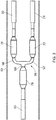
Figure 3 illustrates a conductor transition element with a first leg, a second leg and a third leg arranged on a support element where the first leg of the transition element is connected to a first supply cable in a first joint, the second leg of the transition element is connected to a second supply cable in a second joint, and the third leg of the transition element is connected to an end supply cable in a third joint. -
Figure 4 illustrates a part of a pipeline infigure 1 to which the subsea cable connected for direct electric heating of the pipeline. -
Figure 5 illustrates the conductor transition element infigure 3 where the insulation of the first joint, the second joint and the third joint have been removed and the first connector, the second connector and the third connector are visible. -
Figure 6 illustrates a longitudinal section through the conductor transition element shown infigure 3 . -
Figure 7 illustrates a top view of the conductor transition element. -
Figure 8 illustrates a side view of the conductor transition element shown infigure 7 . -
Figure 9 illustrates a cross section of the conductor transition element shown infigures 7 and8 taken through the first leg and second leg of the conductor transition element. -
Figure 10 illustrates a longitudinal section in a horizontal plane through the conductor transition element shown infigures 7-9 . - A
subsea cable system 10 according to the present invention is shown infigures 1-10 wherefigure 1 shows the complete system. Infigure 1 asubsea cable 11 is shown that is connected to a floating structure comprising adeck 84 and asubsea consumer device 46 of electrical energy. Thesubsea cable 11 may be a subsea riser cable as indicated in the figures, or any other type of suitable subsea cable. The subsea cable comprises a dynamicsubsea cable part 12 that is arranged so that it is, for the most part, floating submerged in the water, and a staticsubsea cable part 17 that is, for the most part, arranged on the seabed. Ananchor device 16 is arranged at or near the seabed comprising asupport part 20 for thesubsea cable 11. Asecond end portion 14 of the dynamicsubsea cable part 12 and afirst end portion 18 of the staticsubsea cable part 17 are preferably joined on thesupport part 20 of theanchor device 16 as indicated infigure 1 . It should be noted that even though thesubsea cable 11 shown in the figures comprises a dynamicsubsea cable part 12 and a staticsubsea cable part 17, the subsea cable does not have to comprise both parts. For example, thesubsea cable 11 may be provided with a dynamicsubsea cable part 12 only that is directly connected to thesubsea consumer device 46. - The dynamic
subsea cable part 12 comprises afirst end portion 13, that is the same as thefirst end portion 26 of thesubsea cable 11, that is connected to a floating structure that comprises adeck 84 or similar on which at least one, but preferably a plurality of topside junction boxes 86 are arranged. - In a known manner, the
first end portion 26 of thesubsea cable 11 may be provided with a hang-offarrangement 87 and afirst guide tube 89 for thesubsea cable 11. Preferably asecond guide tube 90 and a bendingstiffener 85 attached to thesecond guide tube 90 is provided to avoid excessive and potentially damaging bending of thesubsea cable 11. The dynamicsubsea cable part 12 may further be provided with one ormore buoyancy elements 43 as indicated infigure 1 , to obtain the desired shape of the dynamicsubsea cable part 12 in the water. - In the embodiment of the present invention shown in the figures, the subsea consumer device is a part of a pipeline or a
pipeline 46, but the subsea consumer device may also be other types of subsea equipment such as valve devices or subsea transformer devices. - The
second end portion 27 of thesubsea cable 11, which is also the second end portion (19) of the staticsubsea cable part 17, is fastened to afirst end portion 47 of thesubsea pipeline 46. - As shown in
figure 1 , thesecond end portion 27 of thesubsea cable 11 may further be provided with one or more bending restrictors 44 to prevent excessive bending of thesubsea cable 11 and thereby potential damage to thesubsea cable 11. - In
figure 2 , a cross section of asubsea cable 11 according to the present invention is shown. Thesubsea cable 11 infigure 2 is provided with afirst supply cable 21 and asecond supply cable 22 that supply electrical energy from topside junction boxes 86 on the floating structure to thepipeline 46 for direct electrical heating of thepipeline 46. Thesubsea cable 11 shown infigure 2 is also provided with afirst return cable 24 and asecond return cable 25 for the return current from thepipeline 46 to thejunction boxes 86 on the floating structure. - The
first supply cable 21, thesecond supply cable 22, thefirst return cable 24 and thesecond return cable 25 may have the same design as indicated infigure 2 , but may obviously have different designs if that is desired. The two supply cables, 21, 22 and the tworeturn cables figure 2 are therefore described only once herein. - The
cables respective conductor elements conductor elements figure 2 , but may be provided with different shapes if that is considered advantageous. Theconductor elements conductor elements figure 2 , theconductor elements - The supply and return
cables first layer 29 that is arranged aroundrespective conductor elements conductor elements first layer 29 of the supply and returncables - The supply and return
cables second layer 28 that is arranged around respectivefirst layers 29, radially on the outside of the first layers 29. Thesecond layer 28 of the supply and returncables - The supply and return
cables third layer 30 that is arranged around respectivesecond layers 28, radially on the outside of the second layers 28. Thethird layer 30 of the supply and returncables - The supply and return
cables outer sheath 31 that is arranged around respectivethird layers 30, radially on the outside of the third layers 30. Theouter sheath 31 of the supply and returncables - It should be mentioned that this is one possible design of the
first supply cable 21, thesecond supply cable 22, thefirst return cable 24 and thesecond return cable 25, but the supply and returncables conductor elements various layers subsea cable 11. - Around the
first supply cable 21, thesecond supply cable 22, thefirst return cable 24 and thesecond return cable 25, a plurality oflayers subsea cable 11 and protect thefirst supply cable 21, thesecond supply cable 22, thefirst return cable 24 and thesecond return cable 25 and any other cables provided within thesubsea cable 11 from getting damaged. - The embodiment of the
subsea cable 11 shown infigure 2 comprises at least afirst armouring layer 39 and asecond armouring layer 40 that is arranged around thefirst armouring layer 39, radially on the outside of thefirst armouring layer 39. Thefirst armouring layer 39 and thesecond armouring layer 40 may, for example, be made of galvanized steel, but any other suitable material that can provide sufficient strength and is sufficiently resistant to corrosion may be chose for the armouring layers 39, 40. - The
subsea cable 11 further comprises at least oneouter sheath 41 that is arranged around thesecond armouring layer 40, radially on the outside of thesecond armouring layer 40. Theouter sheath 41 may, for example, be made of polyethylene (PE) or polypropylene yarn, but also other materials that are suitable may be chosen as outer sheath material. - It should be noted that the
subsea cable 11 may be provided with fewer or more layers surrounding thefirst supply cable 21, thesecond supply cable 22, thefirst return cable 24 and thesecond return cable 25 than what is shown infigure 2 . - To keep the
first supply cable 21, thesecond supply cable 22, thefirst return cable 24 and thesecond return cable 25 in their positions within thesubsea cable 11, thesubsea cable 11 is provided with a plurality of filler elements that at least partially fill the void between thefirst supply cable 21, thesecond supply cable 22, thefirst return cable 24 and thesecond return cable 25 and the armouring layers 39, 40. - A
first filler element 33 is arranged in the void between thefirst supply cable 21, thesecond supply cable 22 and thefirst armouring layer 39, between thesecond supply cable 22, thefirst return cable 24 and thefirst armouring layer 39, and between thefirst return cable 24, thesecond return cable 22 and thefirst armouring layer 39 as shown infigure 2 . - Between the
first supply cable 21, thesecond return cable 25 and thefirst armouring layer 39 there is provided asecond filler element 34. Thesecond filler element 34 has substantially the same shape as thefirst filler elements 33, but is further provided with acavity 35 extending in the longitudinal direction of thefiller element 34 and thesubsea cable 11. In thecavity 35, for example a fibreoptical cable 38 may be arranged that can be used to send and receive signals from any sensor and control device that thesubsea cable system 10 may be provided with. It would also be possible to provide thefirst filler elements 33 with similar cavities if a number of fibre optical cables or other types of cables are to be included in thesubsea cable 11. - In the middle of the
subsea cable 11, between thefirst supply cable 21, thesecond supply cable 22, thefirst return cable 24 and thesecond return cable 25, athird filler element 36 is provided as shown infigure 2 , in order to further help keeping thecables subsea cable 11. - In
figure 4 , there is shown an enlarged view of the section of thepipeline 46, as shown infigure 1 , to which thesubsea cable system 10 is connected and thereby heating thepipeline 46 by direct electric heating. As indicated infigure 4 , theend portion 19 of thesubsea cable 11 is attached to anarmour block 50 that is attached to thepipeline 46 with apipeline clamp 51. - The
first supply cable 21 and thesecond supply cable 22 extends from thearmour block 50 to aconductor transition element 66 that is mounted to a generally flat surface of thesupport element 63. Thesupport element 63 is securely attached to thepipeline 46 with one ormore fastening elements 64. - The
conductor transition element 66 is provided with three legs, afirst leg 97, asecond leg 98 and athird leg 99, and is preferably given a Y-shaped form as indicated in the figures or alternatively a more T-shaped form. As is clearly shown infigure 3 , thefirst supply cable 21 is connected to thefirst leg 97 of theconductor transition element 66 in a first joint 77 and thesecond supply cable 22 is connected to thesecond leg 98 of theconductor transition element 66 in a second joint 78. - As can be further seen on
figure 3 , thethird leg 99 of theconductor transition element 66 is connected to anend supply cable 53 which, in this embodiment of the invention, is apiggyback cable 53, in a third joint 79. - The
piggyback cable 53 is attached to thepipeline 46 with at least onepiggyback cable clamp 58 and at least onesaddle strap 59 as shown infigure 4 . - The
piggyback cable 53 is terminated at asecond end portion 48 of thepipeline 46 where thepiggyback cable 53 in a known manner is attached to thesecond end portion 48 of thepipeline 46 with atermination arrangement 60 such that the piggyback cable is electrically connected to thesecond end portion 48 of thepipe line 46. - The
first return cable 24 extends from thearmour block 50 and is provided with afirst termination element 92 at its end. Thefirst termination element 92 is mechanically and electrically attached to afirst collector arm 95. Similarly, thesecond return cable 25 extends from thearmour block 50 and is provided with asecond termination element 93 at its end. Thesecond termination element 93 is mechanically and electrically attached to asecond collector arm 96. Thefirst collector arm 95 and thesecond collector arm 96 are both mechanically and electrically connected to acollector device 94 that is mechanically and electrically connected to thefirst end portion 47 of thepipeline 46. Thefirst return cable 24 and thesecond return cable 25 are thereby electrically connected to thepipeline 46 and the electric current that is conducted through thepipeline 46 from thetermination arrangement 60 of thepiggyback cable 53 to thecollector device 94 can thereby flow back to the topside junction boxes 86 on thedeck 84 of the floating structure through thefirst return cable 24 and thesecond return cable 25. - As shown in
figure 1 , thefirst supply cable 21, thesecond supply cable 22, theconductor transition element 66, thefirst return cable 24, thesecond return cable 25 are covered by aprotection cover 62 in a manner well known in the art. - As further indicated in
figure 1 , thepipeline 46 may, in a conventional manner, be provided with at least one, but preferably a plurality of anodes to prevent corrosion of thepipeline 46 and/or the parts of the presentsubsea cable system 10 arranged on thepipeline 46. - The
conductor transition element 66 and thejoints first supply cable 21, thesecond supply cable 22 and thepiggyback cable 53 to theconductor transition element 66 is shown in more detail infigures 5-10 . - As mentioned above, and as shown in
figure 3 and5 , the three-legged, preferably Y-shaped or alternatively T-shaped,conductor transition element 66 comprises afirst leg 97 to which thefirst supply cable 21 is mechanically and electrically connected in a first joint 77, asecond leg 98 to which thesecond supply cable 22 is mechanically and electrically connected in a second joint 77 and athird leg 99 to which thepiggyback cable 53 is mechanically and electrically connected in a third joint 99. - As shown in
figure 7-10 , theconductor transition element 66 comprises a three-legged conductor element 67 that has the same Y-shape, or alternatively T-shape, as the conductor transition element itself. Theconductor element 67 comprises afirst conductor leg 73, asecond conductor leg 74 and athird conductor leg 75. - The
first conductor leg 73 is mechanically and electrically connected to theconductor element 101 of thefirst supply cable 21 with afirst connector device 80. Similarly, thesecond conductor leg 74 is mechanically and electrically connected to theconductor element 102 of thesecond supply cable 22 with a second connector device 81. Thethird conductor leg 75 is mechanically and electrically connected to aconductor element 56 of thepiggyback cable 53 with athird connector device 82. - The
first connector device 80, the second connector device 81 and thethird connector device 82 are preferably of the same type. Theconnector devices first connector device 80, the second connector device 81 and thethird connector device 82 are adapted for mechanical and electrical connection of theconductor element 101 of thefirst supply cable 21 to thefirst conductor leg 73, theconductor element 102 of thesecond supply cable 22 to thesecond conductor leg 74 and theconductor element 56 of thepiggyback cable 53 to thethird conductor leg 75 respectively. Two phases of an electric current, that is split in two phases on the floating structure, is thereby conducted through thefirst supply cable 21 and thesecond supply cable 22 of thesubsea cable 11 and combined into a single phase conducted through the piggy backcable 53 as the electric current is passed through theconductor transition element 66. - It should be noted that in the embodiment of the present invention shown in the figures, the
subsea cable 11 comprises twosupply cables subsea cable 11 with three or more supply cables and providing theconductor transition element 66 with a corresponding number of legs to which the supply cables would be connected plus a leg to which the subsea consumer device or the end supply cable, i.e. the piggy backcable 53, would be connected. The conductor transition element would therefore be fork-shaped instead of Y-shaped. - As shown in
figures 7-10 , theconductor transition element 66 is preferably provided with aninsulation system 68 comprising a plurality of layers as indicated in the figures. Theconductor transition element 66 is preferably prefabricated with theinsulation system 68. - In the embodiment of the
conductor transition element 66 shown infigures 5-10 , theconductor transition element 66 is provided with aninner layer 69. Theinner layer 69 is made of a semiconducting material. The semi-conducting material of theinner layer 69 may be made of, for example, EPR (ethylene-propylene rubber). Radially outside theinner layer 69, there is provided aninsulation layer 70. Theinsulation layer 70 is preferably made of cured, cross linked polyethylene. - The
insulation layer 70 may alternatively be semi-conductive. Asemi-conductive insulation layer 70 may be obtained by mixing a portion of a conductive material, such as carbon black, into polyethylene in a manner known in the art. - Radially outside the
insulation layer 70, there is provided anouter layer 71. Theouter layer 71 is preferably also made of a semi-conducting material. Again, the semi-conducting material may be, for example, EPR (ethylene-propylene rubber). - As shown in
figure 3 , the joint 77, 78, 79 are also provided with insulation covering thefirst connector device 80, the second connector device and thethird connector device 82. The insulation system covering thejoints insulation system 68 of theconductor transition system 66. - The first joint 77, the second joint 78 and the third joint 79 are therefore preferably provided with an insulation system that is the same as the
insulation system 68. Referring to thefigures 7-9 that show theinsulation system 68 in more detail, the insulation system of the first joint 77, the second joint 78 and the third joint 79 therefore comprises aninner layer 69 that is made of a semiconducting material. The semi-conducting material of theinner layer 69 may be made of, for example, EPR (ethylene-propylene rubber). Radially outside theinner layer 69, there is provided aninsulation layer 70. Theinsulation layer 70 is preferably made of cured, cross linked polyethylene. - The
insulation layer 70 may alternatively be semi-conductive. Asemi-conductive insulation layer 70 may be obtained by mixing a portion of a conductive material, such as carbon black, into polyethylene in a manner known in the art. - Radially outside the
insulation layer 70, there is provided anouter layer 71. Theouter layer 71 is preferably also made of a semi-conducting material. Again, the semi-conducting material may be, for example, EPR (ethylene-propylene rubber). - The material used in the
inner layer 69, theinsulation layer 70 and theouter layer 71 of the insulation system of the first joint 77, the second joint 78 and the third joint 79, which is the same insulation system as theinsulation system 68 of theconductor transition element 66, can be in the form of a tape that is self-amalgamating and that is wound around thefirst connector device 80, thefirst connector leg 73 and theconductor element 101 of thefirst supply cable 21 to form the first joint 77, around the second connector device 81, thesecond connector leg 74 and theconductor element 102 of thesecond supply cable 22 to form the second joint 78 and around thethird connector device 82, thethird connector leg 75 and theconductor element 56 of the piggy backcable 53 to form the third joint 79. - The self-amalgamating tape is preferably wound with an overlap for each turn, until a desired thickness of the respective layers of the first joint 77, the second joint 78 and the third joint 79 have been achieved.
- To provide protection against water intrusion, a heat-shrinkable tubing may further by arranged over the insulation system of the first joint 77, the second joint 78 and the third joint 79, but the
joints - The invention has now been explained with reference to a non-limiting example. A person skilled in the art will, however, appreciate that modifications and changes may be made to this embodiment which will be within the scope of the invention as defined in the following claims.
10 Subsea cable system 11 Subsea cable 12 Dynamic riser cable part 13 First end portion (dynamic riser part) 14 Second end portion (dynamic riser part) 15 Midsection 16 Anchor device 17 Static riser cable part (on the seabed) 18 First end portion (static riser part) 19 Second end portion (static riser part) 20 Support part (of anchor) 21 First supply cable 22 Second supply cable 23 24 First return cable 25 Second return cable 26 First end portion (Riser cable) 27 Second end portion (Riser cable) 28 Second layer (middle layer) 29 First layer (inner layer) 30 Third layer (outer layer) 31 Outer sheath (semi conducting) 32 33 First filler element 34 Second filler element 35 Cavity (in second filler element for fibre cable) 36 Third filler element 37 38 Fibre cable 39 First armouring layer 40 Second armouring later 41 Outer sheath 42 43 Bruyancy element (dynamic riser) 44 Bending restrictor (static riser) 45 46 Pipeline (subsea consumer device) 47 First end portion (of pipe line) 48 Second end portion (of pipe line) 49 50 Armour block 51 Pipeline clamp 52 Anode 53 Piggyback cable (end supply cable) 54 First end portion (piggyback cable) 55 Second end portion (piggyback cable) 56 Conductorr element (piggyback cable) 57 58 Piggyback cable clamp 59 Saddle strap (for piggyback cable) 60 Termination arrangement (for piggyback cable at far end pipeline) 61 62 Protection cover (for Y-joint) 63 Support element (for Y-joint) 64 Fastening element (for support element) 65 66 Conductor transition element (Y-joint) 67 Conductor element(Y-shaped) 68 Insulation system (on Y-joint) 69 Inner layer 70 Insulation layer 71 Outer layer 72 73 First conductor leg (for first supply conductor) 74 Secondconductor leg for second supply conductor) 75 Third conducteur leg (for piggyback cable) 76 77 First joint (on first conductor leg) 78 Second joint (on second conductor leg) 79 Third joint (on third conductor leg) 80 First connector device (on first conductor leg - for first sypply conductor) 81 Second connector device (on second conductor leg - for second supply conductor) 82 Third connector device (on third conductor leg - for piggyback cable) 83 84 Deck (topside on platform etc) 85 Bending stiffener 86 Top side junction box (topside supply of electrical energy) 87 Hang-off arrangement 89 First guide tube 90 Second guide tube 91 92 93 First termination element (attached to end of first return conductor) 93 Second termination element (attachement to end second return conductor) 94 Collector device (collecting electric current passing thought pipeline) 95 First collector arm (connected to first termination element) 96 Second collector arm connected to second termination element) 97 First leg (of Y-joint) 98 Second leg (of Y-joint) 99 Third leg (of Y-joint) 100 101 Conductor element (First supply cable) 102 Conductor element (Second supply cable) 103 Conducteur element (First return cable) 104 Conductor element (Second return cable) 105
Claims (15)
- A subsea cable system (10) for transfer of electric power to a subsea device, the subsea cable system comprising a subsea cable (11) with a first end portion (26) and a second end portion (27) where the first end portion (26) is adapted for connection to a supply of electrical energy (86), the subsea cable (11) comprising at least a first supply cable (21), a second supply cable (22) and at least one return cable (24, 25), the first supply cable (21), the second supply cable (22) and the at least one return cable (24, 25) each comprising a conductor element (101, 102, 103, 104) for conduction of an electric current, the subsea cable system (10) further comprising a conductor transition element (66) comprising a conductor element (67) that is provided with at least a first conductor leg (73), a second conductor leg (74) and a third conductor leg (75) where the first conductor leg (73) is connected to the conductor element (101) of the first supply cable (21), the second conductor leg (74) is connected to the conductor element (102) of the second supply cable (22) and the third conductor leg (75) is connectable to a subsea consumer device (46).
- Subsea cable system according to claim 1,
wherein the conductor transition element (66) is generally Y-shaped or T-shaped and comprises a first leg (97) that includes the first conductor leg (73), a second leg (98) that includes the second conductor leg (74) and a third leg (99) that includes the third conductor leg (75). - Subsea cable system according to claim 1 or 2,
wherein the conductor transition element (66) is provided with an insulation system (68) comprising at least an inner layer (69), an outer layer (71) and an insulation layer (70) that is arranged between the inner layer (69) and the outer layer (71). - Subsea cable system according to claim 3,
wherein the inner layer (69) is made of a semi-conducting material, the insulation layer (70) is made of cured, cross linked poly ethylene and the outer layer (71) is made of a semi-conducting material. - Subsea cable system according to any one of claims 1-4,
wherein the first leg of the conductor transition element (66) is provided with a first connector device (80) for connection of the first supply cable (21) to the first leg (97), the second leg of the conductor transition element (66) is provided with a second connector device (81) for connection of the second supply cable (22) to the second leg (98) and the third leg of the conductor transition element (66) is provided with a third connector device (82) for connection of the subsea consumer device to the third leg (99). - Subsea cable system according to claim 5,
wherein the first connector device (80), the second connector device (81) and the third connector device (82) each comprise compression ferrules. - Subsea cable system according to claim 6,
wherein the compression ferrules of the first connector device (80), the second connector device (81) and the third connector device (82) are adapted for mechanical and/or electrical connection of the conductor element (101) of the first supply cable (21) to the first conductor leg (73) of the first leg (97), the conductor element (102) of the second supply cable (22) to the second conductor leg (74) of the second leg (98) and the subsea consumer device (46) to the third conductor leg (75) of the third leg (99) respectively. - Subsea cable system according to any one of claims 5-7,
wherein the first connector device (80), the second connector device (81) and the third connector device (82) are each provided with an insulation system. - Subsea cable system according to any one of claims 1-8,
wherein the subsea cable (11) comprises at least a first return cable (24) and a second return cable (25) for the return current. - Subsea cable system according to any one of claims 1-9,
wherein the subsea consumer device (46) is a pipeline and the subsea cable system further comprises an end supply cable (53) that is connected to the third leg (99) of the conductor transition element (66) and to the pipeline (46). - Subsea cable system according to claim 10,
wherein the conductor transition element (66) is attached to a support element (63) that is attached to the pipeline (46). - Subsea cable system according to claim 10 or 11,
wherein the piggyback cable (53) is electrically connected to a second end portion (48) of the pipeline (46) and the at least one return cable (24, 25) is electrically connected to a first end portion (47) of the pipeline (46) whereby the pipeline can be heated by an electric current passing through the pipeline (46). - A method for supplying electrical power to a subsea consumer device (46) of electricity, the subsea consumer device (46) being adapted for subsea use, wherein:- a subsea cable (11) comprising at least a first supply cable (21), a second supply cable (22) and at least one return cable (24, 25), is provided;- a first end portion (26) of the subsea cable (11) is connected to a supply of electrical energy (86) arranged on an offshore structure;- the at least one return cable (24, 25) of the subsea cable (11) is connected to the subsea consumer device (46) at a second end portion (27) of the subsea cable (11);- at the second end portion (27) of the subsea cable (11), the first supply cable (21) is connected to a first conductor leg (73) of a conductor transition element (66) and the second supply cable (22) is connected to a second conductor leg (74) of the conductor transition element (66);- a third conductor leg (75) of the conductor transition element (66) is connected to the subsea consumer device;whereby the subsea consumer device (46) can be provided with electrical power.
- Method according to claim 13,
wherein at least one of the steps are carried out on one or more floating vessels before and/or during the laying of the subsea cable (11), the conductor transition element (66) and the subsea consumer device (46). - Use of a subsea cable system according to any one of claims 1-12 and/or a method according to any one of the claims 13-14 for heating of a subsea cable.
Priority Applications (6)
| Application Number | Priority Date | Filing Date | Title |
|---|---|---|---|
| FIEP17306498.1T FI3477179T3 (en) | 2017-10-31 | 2017-10-31 | A subsea cable system and a method for supplying electrical power to a subsea device |
| DK17306498.1T DK3477179T3 (en) | 2017-10-31 | 2017-10-31 | UNDERWATER CABLE SYSTEM AND METHOD FOR SUPPLYING ELECTRICAL ENERGY TO AN UNDERWATER DEVICE |
| EP17306498.1A EP3477179B1 (en) | 2017-10-31 | 2017-10-31 | A subsea cable system and a method for supplying electrical power to a subsea device |
| AU2018250364A AU2018250364B2 (en) | 2017-10-31 | 2018-10-16 | A subsea cable system and a method for supplying electrical power to a subsea device |
| BR102018071955-6A BR102018071955A2 (en) | 2017-10-31 | 2018-10-25 | A SUBMARINE CABLE SYSTEM AND METHOD FOR PROVIDING ELECTRIC ENERGY TO A SUBMARINE DEVICE |
| US16/172,129 US11170915B2 (en) | 2017-10-31 | 2018-10-26 | Subsea cable system and a method for supplying electrical power to a subsea device |
Applications Claiming Priority (1)
| Application Number | Priority Date | Filing Date | Title |
|---|---|---|---|
| EP17306498.1A EP3477179B1 (en) | 2017-10-31 | 2017-10-31 | A subsea cable system and a method for supplying electrical power to a subsea device |
Publications (2)
| Publication Number | Publication Date |
|---|---|
| EP3477179A1 true EP3477179A1 (en) | 2019-05-01 |
| EP3477179B1 EP3477179B1 (en) | 2022-09-14 |
Family
ID=60327243
Family Applications (1)
| Application Number | Title | Priority Date | Filing Date |
|---|---|---|---|
| EP17306498.1A Active EP3477179B1 (en) | 2017-10-31 | 2017-10-31 | A subsea cable system and a method for supplying electrical power to a subsea device |
Country Status (6)
| Country | Link |
|---|---|
| US (1) | US11170915B2 (en) |
| EP (1) | EP3477179B1 (en) |
| AU (1) | AU2018250364B2 (en) |
| BR (1) | BR102018071955A2 (en) |
| DK (1) | DK3477179T3 (en) |
| FI (1) | FI3477179T3 (en) |
Cited By (1)
| Publication number | Priority date | Publication date | Assignee | Title |
|---|---|---|---|---|
| EP4220878A1 (en) * | 2022-01-31 | 2023-08-02 | NKT HV Cables AB | Hvdc power cable multi-branch joint assembly |
Families Citing this family (2)
| Publication number | Priority date | Publication date | Assignee | Title |
|---|---|---|---|---|
| NO345645B1 (en) * | 2017-11-27 | 2021-05-25 | Nexans | Subsea connector |
| CN115410760A (en) * | 2021-05-27 | 2022-11-29 | 中国海洋大学 | Zero-buoyancy cable and deep sea equipment |
Citations (3)
| Publication number | Priority date | Publication date | Assignee | Title |
|---|---|---|---|---|
| GB2352082A (en) * | 1999-06-17 | 2001-01-17 | Cit Alcatel | Electrical subsea cable sheathing |
| WO2004111519A1 (en) * | 2003-06-18 | 2004-12-23 | Statoil Asa | Method and system for direct electric heating of a pipeline |
| WO2010135772A1 (en) * | 2009-05-25 | 2010-12-02 | Woodside Energy Limited | Direct electric heating of subsea piping installations |
Family Cites Families (3)
| Publication number | Priority date | Publication date | Assignee | Title |
|---|---|---|---|---|
| US5577926A (en) * | 1994-12-05 | 1996-11-26 | Texaco, Inc. | Pressure equalization adapter for subsea cable termination or junction box |
| NO318001B1 (en) * | 2002-09-02 | 2005-01-17 | Nexans | Method for manufacturing an electrical cable system |
| NO20050772A (en) * | 2005-02-11 | 2006-03-13 | Nexans | Underwater umbilical and method of its manufacture |
-
2017
- 2017-10-31 EP EP17306498.1A patent/EP3477179B1/en active Active
- 2017-10-31 FI FIEP17306498.1T patent/FI3477179T3/en active
- 2017-10-31 DK DK17306498.1T patent/DK3477179T3/en active
-
2018
- 2018-10-16 AU AU2018250364A patent/AU2018250364B2/en active Active
- 2018-10-25 BR BR102018071955-6A patent/BR102018071955A2/en not_active IP Right Cessation
- 2018-10-26 US US16/172,129 patent/US11170915B2/en active Active
Patent Citations (3)
| Publication number | Priority date | Publication date | Assignee | Title |
|---|---|---|---|---|
| GB2352082A (en) * | 1999-06-17 | 2001-01-17 | Cit Alcatel | Electrical subsea cable sheathing |
| WO2004111519A1 (en) * | 2003-06-18 | 2004-12-23 | Statoil Asa | Method and system for direct electric heating of a pipeline |
| WO2010135772A1 (en) * | 2009-05-25 | 2010-12-02 | Woodside Energy Limited | Direct electric heating of subsea piping installations |
Non-Patent Citations (2)
| Title |
|---|
| NEXANS: "Subsea Technology", 31 January 2008 (2008-01-31), XP002779690, Retrieved from the Internet <URL:http://www.nexans.no/Norway/2008/0152_NEX_Brosj_Subsea_folder.pdf> [retrieved on 20180329] * |
| SWCC SHOWA HOLDINGS CO., LTD: "Cable Joint", 31 December 2016 (2016-12-31), XP002780788, Retrieved from the Internet <URL:http://www.swcc.co.jp/eng/products/siconex/cable_joint.html> [retrieved on 20180504] * |
Cited By (1)
| Publication number | Priority date | Publication date | Assignee | Title |
|---|---|---|---|---|
| EP4220878A1 (en) * | 2022-01-31 | 2023-08-02 | NKT HV Cables AB | Hvdc power cable multi-branch joint assembly |
Also Published As
| Publication number | Publication date |
|---|---|
| DK3477179T3 (en) | 2022-12-05 |
| US20190164666A1 (en) | 2019-05-30 |
| FI3477179T3 (en) | 2022-12-15 |
| US11170915B2 (en) | 2021-11-09 |
| AU2018250364A1 (en) | 2019-05-16 |
| AU2018250364B2 (en) | 2023-12-14 |
| BR102018071955A2 (en) | 2019-06-04 |
| EP3477179B1 (en) | 2022-09-14 |
Similar Documents
| Publication | Publication Date | Title |
|---|---|---|
| US6371693B1 (en) | Making subsea pipelines ready for electrical heating | |
| US7381900B2 (en) | Power cable for direct electric heating system | |
| US7285726B2 (en) | Subsea power cable | |
| US6049657A (en) | Marine pipeline heated with alternating current | |
| US11170915B2 (en) | Subsea cable system and a method for supplying electrical power to a subsea device | |
| US5256844A (en) | Arrangement in a pipeline transportation system | |
| AU631152B2 (en) | Method for heating a transport pipeline, as well as transport pipeline with heating | |
| AU2016245945B2 (en) | Method of installing an electrically-heatable subsea flowline and electrically -heatable subsea flowline thereof | |
| US6556780B2 (en) | Heated flowline umbilical | |
| US11174995B2 (en) | Hydrate remediation systems, apparatuses and methods of making and using same | |
| US10985544B2 (en) | Subsea connector with u-shaped configuration | |
| EA011539B1 (en) | System for power supply to subsea installations | |
| US11270812B2 (en) | Power umbilical with impact protection | |
| US20120125906A1 (en) | Thermally isolated heated pipeline made of double casing sections and laying process for such a pipeline | |
| US20130108251A1 (en) | Pipeline | |
| WO1997036063A1 (en) | Heated offshore pipeline and method of manufacturing | |
| US20160211054A1 (en) | Downhole cable with intergrated non-metallic tube | |
| Lervik et al. | High frequency heating of subsea oil production pipelines | |
| US20220252198A1 (en) | Underwater heated pipe for the transport of fluids and method for assembling such a pipe | |
| JPS6249520B2 (en) | ||
| NO20210762A1 (en) | An umbilical cable system and appurtenant method | |
| NO20150428A1 (en) | Installing Heated Subsea Pipelines |
Legal Events
| Date | Code | Title | Description |
|---|---|---|---|
| PUAI | Public reference made under article 153(3) epc to a published international application that has entered the european phase |
Free format text: ORIGINAL CODE: 0009012 |
|
| STAA | Information on the status of an ep patent application or granted ep patent |
Free format text: STATUS: THE APPLICATION HAS BEEN PUBLISHED |
|
| AK | Designated contracting states |
Kind code of ref document: A1 Designated state(s): AL AT BE BG CH CY CZ DE DK EE ES FI FR GB GR HR HU IE IS IT LI LT LU LV MC MK MT NL NO PL PT RO RS SE SI SK SM TR |
|
| AX | Request for extension of the european patent |
Extension state: BA ME |
|
| STAA | Information on the status of an ep patent application or granted ep patent |
Free format text: STATUS: REQUEST FOR EXAMINATION WAS MADE |
|
| STAA | Information on the status of an ep patent application or granted ep patent |
Free format text: STATUS: EXAMINATION IS IN PROGRESS |
|
| 17P | Request for examination filed |
Effective date: 20191104 |
|
| RBV | Designated contracting states (corrected) |
Designated state(s): AL AT BE BG CH CY CZ DE DK EE ES FI FR GB GR HR HU IE IS IT LI LT LU LV MC MK MT NL NO PL PT RO RS SE SI SK SM TR |
|
| 17Q | First examination report despatched |
Effective date: 20191122 |
|
| STAA | Information on the status of an ep patent application or granted ep patent |
Free format text: STATUS: EXAMINATION IS IN PROGRESS |
|
| STAA | Information on the status of an ep patent application or granted ep patent |
Free format text: STATUS: EXAMINATION IS IN PROGRESS |
|
| GRAP | Despatch of communication of intention to grant a patent |
Free format text: ORIGINAL CODE: EPIDOSNIGR1 |
|
| STAA | Information on the status of an ep patent application or granted ep patent |
Free format text: STATUS: GRANT OF PATENT IS INTENDED |
|
| INTG | Intention to grant announced |
Effective date: 20220603 |
|
| GRAS | Grant fee paid |
Free format text: ORIGINAL CODE: EPIDOSNIGR3 |
|
| GRAA | (expected) grant |
Free format text: ORIGINAL CODE: 0009210 |
|
| STAA | Information on the status of an ep patent application or granted ep patent |
Free format text: STATUS: THE PATENT HAS BEEN GRANTED |
|
| AK | Designated contracting states |
Kind code of ref document: B1 Designated state(s): AL AT BE BG CH CY CZ DE DK EE ES FI FR GB GR HR HU IE IS IT LI LT LU LV MC MK MT NL NO PL PT RO RS SE SI SK SM TR |
|
| REG | Reference to a national code |
Ref country code: GB Ref legal event code: FG4D |
|
| REG | Reference to a national code |
Ref country code: CH Ref legal event code: EP |
|
| REG | Reference to a national code |
Ref country code: DE Ref legal event code: R096 Ref document number: 602017061754 Country of ref document: DE |
|
| REG | Reference to a national code |
Ref country code: IE Ref legal event code: FG4D |
|
| REG | Reference to a national code |
Ref country code: AT Ref legal event code: REF Ref document number: 1518885 Country of ref document: AT Kind code of ref document: T Effective date: 20221015 |
|
| REG | Reference to a national code |
Ref country code: DK Ref legal event code: T3 Effective date: 20221130 |
|
| REG | Reference to a national code |
Ref country code: NO Ref legal event code: T2 Effective date: 20220914 |
|
| REG | Reference to a national code |
Ref country code: SE Ref legal event code: TRGR |
|
| REG | Reference to a national code |
Ref country code: NL Ref legal event code: FP |
|
| REG | Reference to a national code |
Ref country code: LT Ref legal event code: MG9D |
|
| PG25 | Lapsed in a contracting state [announced via postgrant information from national office to epo] |
Ref country code: RS Free format text: LAPSE BECAUSE OF FAILURE TO SUBMIT A TRANSLATION OF THE DESCRIPTION OR TO PAY THE FEE WITHIN THE PRESCRIBED TIME-LIMIT Effective date: 20220914 Ref country code: LV Free format text: LAPSE BECAUSE OF FAILURE TO SUBMIT A TRANSLATION OF THE DESCRIPTION OR TO PAY THE FEE WITHIN THE PRESCRIBED TIME-LIMIT Effective date: 20220914 Ref country code: LT Free format text: LAPSE BECAUSE OF FAILURE TO SUBMIT A TRANSLATION OF THE DESCRIPTION OR TO PAY THE FEE WITHIN THE PRESCRIBED TIME-LIMIT Effective date: 20220914 |
|
| REG | Reference to a national code |
Ref country code: AT Ref legal event code: MK05 Ref document number: 1518885 Country of ref document: AT Kind code of ref document: T Effective date: 20220914 |
|
| PG25 | Lapsed in a contracting state [announced via postgrant information from national office to epo] |
Ref country code: HR Free format text: LAPSE BECAUSE OF FAILURE TO SUBMIT A TRANSLATION OF THE DESCRIPTION OR TO PAY THE FEE WITHIN THE PRESCRIBED TIME-LIMIT Effective date: 20220914 Ref country code: GR Free format text: LAPSE BECAUSE OF FAILURE TO SUBMIT A TRANSLATION OF THE DESCRIPTION OR TO PAY THE FEE WITHIN THE PRESCRIBED TIME-LIMIT Effective date: 20221215 |
|
| PG25 | Lapsed in a contracting state [announced via postgrant information from national office to epo] |
Ref country code: SM Free format text: LAPSE BECAUSE OF FAILURE TO SUBMIT A TRANSLATION OF THE DESCRIPTION OR TO PAY THE FEE WITHIN THE PRESCRIBED TIME-LIMIT Effective date: 20220914 Ref country code: RO Free format text: LAPSE BECAUSE OF FAILURE TO SUBMIT A TRANSLATION OF THE DESCRIPTION OR TO PAY THE FEE WITHIN THE PRESCRIBED TIME-LIMIT Effective date: 20220914 Ref country code: PT Free format text: LAPSE BECAUSE OF FAILURE TO SUBMIT A TRANSLATION OF THE DESCRIPTION OR TO PAY THE FEE WITHIN THE PRESCRIBED TIME-LIMIT Effective date: 20230116 Ref country code: ES Free format text: LAPSE BECAUSE OF FAILURE TO SUBMIT A TRANSLATION OF THE DESCRIPTION OR TO PAY THE FEE WITHIN THE PRESCRIBED TIME-LIMIT Effective date: 20220914 Ref country code: CZ Free format text: LAPSE BECAUSE OF FAILURE TO SUBMIT A TRANSLATION OF THE DESCRIPTION OR TO PAY THE FEE WITHIN THE PRESCRIBED TIME-LIMIT Effective date: 20220914 Ref country code: AT Free format text: LAPSE BECAUSE OF FAILURE TO SUBMIT A TRANSLATION OF THE DESCRIPTION OR TO PAY THE FEE WITHIN THE PRESCRIBED TIME-LIMIT Effective date: 20220914 |
|
| PG25 | Lapsed in a contracting state [announced via postgrant information from national office to epo] |
Ref country code: SK Free format text: LAPSE BECAUSE OF FAILURE TO SUBMIT A TRANSLATION OF THE DESCRIPTION OR TO PAY THE FEE WITHIN THE PRESCRIBED TIME-LIMIT Effective date: 20220914 Ref country code: PL Free format text: LAPSE BECAUSE OF FAILURE TO SUBMIT A TRANSLATION OF THE DESCRIPTION OR TO PAY THE FEE WITHIN THE PRESCRIBED TIME-LIMIT Effective date: 20220914 Ref country code: IS Free format text: LAPSE BECAUSE OF FAILURE TO SUBMIT A TRANSLATION OF THE DESCRIPTION OR TO PAY THE FEE WITHIN THE PRESCRIBED TIME-LIMIT Effective date: 20230114 Ref country code: EE Free format text: LAPSE BECAUSE OF FAILURE TO SUBMIT A TRANSLATION OF THE DESCRIPTION OR TO PAY THE FEE WITHIN THE PRESCRIBED TIME-LIMIT Effective date: 20220914 |
|
| REG | Reference to a national code |
Ref country code: CH Ref legal event code: PL |
|
| REG | Reference to a national code |
Ref country code: DE Ref legal event code: R097 Ref document number: 602017061754 Country of ref document: DE |
|
| REG | Reference to a national code |
Ref country code: BE Ref legal event code: MM Effective date: 20221031 |
|
| PG25 | Lapsed in a contracting state [announced via postgrant information from national office to epo] |
Ref country code: MC Free format text: LAPSE BECAUSE OF FAILURE TO SUBMIT A TRANSLATION OF THE DESCRIPTION OR TO PAY THE FEE WITHIN THE PRESCRIBED TIME-LIMIT Effective date: 20220914 Ref country code: LU Free format text: LAPSE BECAUSE OF NON-PAYMENT OF DUE FEES Effective date: 20221031 Ref country code: AL Free format text: LAPSE BECAUSE OF FAILURE TO SUBMIT A TRANSLATION OF THE DESCRIPTION OR TO PAY THE FEE WITHIN THE PRESCRIBED TIME-LIMIT Effective date: 20220914 |
|
| PLBE | No opposition filed within time limit |
Free format text: ORIGINAL CODE: 0009261 |
|
| STAA | Information on the status of an ep patent application or granted ep patent |
Free format text: STATUS: NO OPPOSITION FILED WITHIN TIME LIMIT |
|
| PG25 | Lapsed in a contracting state [announced via postgrant information from national office to epo] |
Ref country code: LI Free format text: LAPSE BECAUSE OF NON-PAYMENT OF DUE FEES Effective date: 20221031 Ref country code: CH Free format text: LAPSE BECAUSE OF NON-PAYMENT OF DUE FEES Effective date: 20221031 |
|
| 26N | No opposition filed |
Effective date: 20230615 |
|
| PG25 | Lapsed in a contracting state [announced via postgrant information from national office to epo] |
Ref country code: SI Free format text: LAPSE BECAUSE OF FAILURE TO SUBMIT A TRANSLATION OF THE DESCRIPTION OR TO PAY THE FEE WITHIN THE PRESCRIBED TIME-LIMIT Effective date: 20220914 |
|
| PG25 | Lapsed in a contracting state [announced via postgrant information from national office to epo] |
Ref country code: BE Free format text: LAPSE BECAUSE OF NON-PAYMENT OF DUE FEES Effective date: 20221031 |
|
| PG25 | Lapsed in a contracting state [announced via postgrant information from national office to epo] |
Ref country code: IE Free format text: LAPSE BECAUSE OF NON-PAYMENT OF DUE FEES Effective date: 20221031 |
|
| PGFP | Annual fee paid to national office [announced via postgrant information from national office to epo] |
Ref country code: NL Payment date: 20231019 Year of fee payment: 7 |
|
| PGFP | Annual fee paid to national office [announced via postgrant information from national office to epo] |
Ref country code: GB Payment date: 20231020 Year of fee payment: 7 |
|
| PGFP | Annual fee paid to national office [announced via postgrant information from national office to epo] |
Ref country code: SE Payment date: 20231019 Year of fee payment: 7 Ref country code: NO Payment date: 20231025 Year of fee payment: 7 Ref country code: FR Payment date: 20231026 Year of fee payment: 7 Ref country code: FI Payment date: 20231020 Year of fee payment: 7 Ref country code: DK Payment date: 20231024 Year of fee payment: 7 Ref country code: DE Payment date: 20231020 Year of fee payment: 7 |
|
| PG25 | Lapsed in a contracting state [announced via postgrant information from national office to epo] |
Ref country code: HU Free format text: LAPSE BECAUSE OF FAILURE TO SUBMIT A TRANSLATION OF THE DESCRIPTION OR TO PAY THE FEE WITHIN THE PRESCRIBED TIME-LIMIT; INVALID AB INITIO Effective date: 20171031 |
|
| PG25 | Lapsed in a contracting state [announced via postgrant information from national office to epo] |
Ref country code: CY Free format text: LAPSE BECAUSE OF FAILURE TO SUBMIT A TRANSLATION OF THE DESCRIPTION OR TO PAY THE FEE WITHIN THE PRESCRIBED TIME-LIMIT Effective date: 20220914 |
|
| PG25 | Lapsed in a contracting state [announced via postgrant information from national office to epo] |
Ref country code: MK Free format text: LAPSE BECAUSE OF FAILURE TO SUBMIT A TRANSLATION OF THE DESCRIPTION OR TO PAY THE FEE WITHIN THE PRESCRIBED TIME-LIMIT Effective date: 20220914 Ref country code: IT Free format text: LAPSE BECAUSE OF FAILURE TO SUBMIT A TRANSLATION OF THE DESCRIPTION OR TO PAY THE FEE WITHIN THE PRESCRIBED TIME-LIMIT Effective date: 20220914 |
|
| PG25 | Lapsed in a contracting state [announced via postgrant information from national office to epo] |
Ref country code: BG Free format text: LAPSE BECAUSE OF FAILURE TO SUBMIT A TRANSLATION OF THE DESCRIPTION OR TO PAY THE FEE WITHIN THE PRESCRIBED TIME-LIMIT Effective date: 20220914 |