EP3477056A2 - Gas turbine engine airfoil array - Google Patents
Gas turbine engine airfoil array Download PDFInfo
- Publication number
- EP3477056A2 EP3477056A2 EP18202713.6A EP18202713A EP3477056A2 EP 3477056 A2 EP3477056 A2 EP 3477056A2 EP 18202713 A EP18202713 A EP 18202713A EP 3477056 A2 EP3477056 A2 EP 3477056A2
- Authority
- EP
- European Patent Office
- Prior art keywords
- airfoil
- profiled region
- endwall
- array
- profiled
- Prior art date
- Legal status (The legal status is an assumption and is not a legal conclusion. Google has not performed a legal analysis and makes no representation as to the accuracy of the status listed.)
- Granted
Links
Images


Classifications
-
- F—MECHANICAL ENGINEERING; LIGHTING; HEATING; WEAPONS; BLASTING
- F01—MACHINES OR ENGINES IN GENERAL; ENGINE PLANTS IN GENERAL; STEAM ENGINES
- F01D—NON-POSITIVE DISPLACEMENT MACHINES OR ENGINES, e.g. STEAM TURBINES
- F01D5/00—Blades; Blade-carrying members; Heating, heat-insulating, cooling or antivibration means on the blades or the members
- F01D5/12—Blades
- F01D5/14—Form or construction
- F01D5/141—Shape, i.e. outer, aerodynamic form
- F01D5/145—Means for influencing boundary layers or secondary circulations
-
- F—MECHANICAL ENGINEERING; LIGHTING; HEATING; WEAPONS; BLASTING
- F01—MACHINES OR ENGINES IN GENERAL; ENGINE PLANTS IN GENERAL; STEAM ENGINES
- F01D—NON-POSITIVE DISPLACEMENT MACHINES OR ENGINES, e.g. STEAM TURBINES
- F01D5/00—Blades; Blade-carrying members; Heating, heat-insulating, cooling or antivibration means on the blades or the members
- F01D5/12—Blades
- F01D5/14—Form or construction
- F01D5/141—Shape, i.e. outer, aerodynamic form
- F01D5/142—Shape, i.e. outer, aerodynamic form of the blades of successive rotor or stator blade-rows
- F01D5/143—Contour of the outer or inner working fluid flow path wall, i.e. shroud or hub contour
-
- F—MECHANICAL ENGINEERING; LIGHTING; HEATING; WEAPONS; BLASTING
- F04—POSITIVE - DISPLACEMENT MACHINES FOR LIQUIDS; PUMPS FOR LIQUIDS OR ELASTIC FLUIDS
- F04D—NON-POSITIVE-DISPLACEMENT PUMPS
- F04D29/00—Details, component parts, or accessories
- F04D29/66—Combating cavitation, whirls, noise, vibration or the like; Balancing
- F04D29/68—Combating cavitation, whirls, noise, vibration or the like; Balancing by influencing boundary layers
-
- F—MECHANICAL ENGINEERING; LIGHTING; HEATING; WEAPONS; BLASTING
- F01—MACHINES OR ENGINES IN GENERAL; ENGINE PLANTS IN GENERAL; STEAM ENGINES
- F01D—NON-POSITIVE DISPLACEMENT MACHINES OR ENGINES, e.g. STEAM TURBINES
- F01D9/00—Stators
- F01D9/02—Nozzles; Nozzle boxes; Stator blades; Guide conduits, e.g. individual nozzles
- F01D9/04—Nozzles; Nozzle boxes; Stator blades; Guide conduits, e.g. individual nozzles forming ring or sector
- F01D9/041—Nozzles; Nozzle boxes; Stator blades; Guide conduits, e.g. individual nozzles forming ring or sector using blades
-
- F—MECHANICAL ENGINEERING; LIGHTING; HEATING; WEAPONS; BLASTING
- F04—POSITIVE - DISPLACEMENT MACHINES FOR LIQUIDS; PUMPS FOR LIQUIDS OR ELASTIC FLUIDS
- F04D—NON-POSITIVE-DISPLACEMENT PUMPS
- F04D29/00—Details, component parts, or accessories
- F04D29/40—Casings; Connections of working fluid
- F04D29/52—Casings; Connections of working fluid for axial pumps
- F04D29/522—Casings; Connections of working fluid for axial pumps especially adapted for elastic fluid pumps
-
- F—MECHANICAL ENGINEERING; LIGHTING; HEATING; WEAPONS; BLASTING
- F05—INDEXING SCHEMES RELATING TO ENGINES OR PUMPS IN VARIOUS SUBCLASSES OF CLASSES F01-F04
- F05D—INDEXING SCHEME FOR ASPECTS RELATING TO NON-POSITIVE-DISPLACEMENT MACHINES OR ENGINES, GAS-TURBINES OR JET-PROPULSION PLANTS
- F05D2240/00—Components
- F05D2240/10—Stators
- F05D2240/12—Fluid guiding means, e.g. vanes
-
- Y—GENERAL TAGGING OF NEW TECHNOLOGICAL DEVELOPMENTS; GENERAL TAGGING OF CROSS-SECTIONAL TECHNOLOGIES SPANNING OVER SEVERAL SECTIONS OF THE IPC; TECHNICAL SUBJECTS COVERED BY FORMER USPC CROSS-REFERENCE ART COLLECTIONS [XRACs] AND DIGESTS
- Y02—TECHNOLOGIES OR APPLICATIONS FOR MITIGATION OR ADAPTATION AGAINST CLIMATE CHANGE
- Y02T—CLIMATE CHANGE MITIGATION TECHNOLOGIES RELATED TO TRANSPORTATION
- Y02T50/00—Aeronautics or air transport
- Y02T50/60—Efficient propulsion technologies, e.g. for aircraft
Definitions
- a gas turbine engine typically includes a fan section, a compressor section, a combustor section, and a turbine section. Air entering the compressor section is compressed and delivered into the combustion section where it is mixed with fuel and ignited to generate a high-speed exhaust gas flow. The high-speed exhaust gas flow expands through the turbine section to drive the compressor and the fan section.
- Some sections of the engine include arrays of airfoils circumferentially spaced from each other forming fluid flow passages between adjacent airfoils for air to pass.
- the fluid flow passages are established by adjacent airfoils projecting from laterally extending endwalls. Near the endwalls, the fluid flow is dominated by a flow phenomenon known as a horseshoe vortex, which forms as a result of the endwall boundary layer separating from the endwall as the gas approaches the leading edges of the airfoils.
- the separated gas reorganizes into the horseshoe vortex.
- There is a loss of efficiency associated with the vortex and this loss is referred to as "secondary" or endwall loss. Accordingly, there exists a need for a way to mitigate or reduce endwall losses.
- an airfoil array includes an endwall.
- a first airfoil and a second airfoil each extend radially from the endwall and have a first side and an opposite second side that extends along an axially chord between a leading edge and a trailing edge.
- a first profiled region is recessed into the endwall along the first side of the first airfoil.
- a second profiled region protrudes from the endwall approximately equidistant from the first side of the first airfoil and the second side of the second airfoil.
- a third profiled region is recessed into the endwall along adjacent the leading edge of the second side of the second airfoil. The third profiled region is at least partially axially aligned with the second profiled region.
- the first profiled region extends approximately 100% of the axial chord.
- the first profiled region extends approximately 30% of the pitch between the first airfoil and the second airfoil.
- the first profiled region includes a lower most surface located in a forward 30% of the axial chord.
- the second profiled region extends along approximately a forward 30% of the axial chord and extends along approximately 30% of the pitch between the first airfoil and the second airfoil.
- the third profiled region extends along approximately a forward 30% of the axial chord and extends along approximately 30% of the pitch between the first airfoil and the second airfoil.
- a fourth profiled region protrudes from the endwall along the second side of the second airfoil downstream from the third profiled region.
- a fifth profiled region protrudes from the endwall along the first side of the first airfoil upstream of the first profiled region.
- the fourth profiled region extends along approximately an aft 50% axial chord and extends along approximately 50% of the pitch between the first airfoil and the second airfoil.
- the fifth profiled region extends along approximately a forward 10% of the axial chord and extends along approximately 10% of the pitch between the first airfoil and the second airfoil.
- a gas turbine engine in another aspect of the present invention, includes a compressor section.
- a turbine section is located downstream of the compressor section.
- At least one of the compressor section or the turbine section includes an array of airfoils including an endwall.
- a first airfoil and a second airfoil each extend radially from the endwall and have a first side and an opposite second side that extend along an axially chord between a leading edge and a trailing edge.
- a first profiled region is recessed into the endwall along the first side of the first airfoil.
- a second profiled region protrudes from the endwall approximately equidistant from the first side of the first airfoil and the second side of the second airfoil.
- a third profiled region is recessed into the endwall along adjacent the leading edge of the second side of the second airfoil. The third profiled region is at least partially axially aligned with the second profiled region.
- the engine may be a geared engine.
- the first profiled region extends approximately 100% of the axial chord.
- the first profiled region extends approximately 30% of the pitch between the first airfoil and the second airfoil.
- the first profiled region includes a lower most surface located in a forward 30% of the axial chord.
- the second profiled region extends along approximately a forward 30% of the axial chord and extends along approximately 30% of the pitch between the first airfoil and the second airfoil.
- the third profiled region extends along approximately a forward 30% of the axial chord and extends along approximately 30% of the pitch between the first airfoil and the second airfoil.
- a fourth profiled region protrudes from the endwall along the second side of the second airfoil downstream from the third profiled region.
- a fifth profiled region protrudes from the endwall along the first side of the first airfoil upstream of the first profiled region.
- the fourth profiled region extends along approximately an aft 50% axial chord and extends along approximately 50% of the pitch between the first airfoil and the second airfoil.
- the fifth profiled region extends along approximately a forward 10% of the axial chord and extends along approximately 10% of the pitch between the first airfoil and the second airfoil.
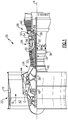
- FIG. 1 schematically illustrates a gas turbine engine 20.
- the gas turbine engine 20 is disclosed herein as a two-spool turbofan that generally incorporates a fan section 22, a compressor section 24, a combustor section 26 and a turbine section 28.
- Alternative engines might include an augmentor section (not shown) among other systems or features.
- the fan section 22 drives air along a bypass flow path B in a bypass duct defined within a nacelle 15, and also drives air along a core flow path C for compression and communication into the combustor section 26 then expansion through the turbine section 28.
- the exemplary engine 20 generally includes a low speed spool 30 and a high speed spool 32 mounted for rotation about an engine central longitudinal axis A relative to an engine static structure 36 via several bearing systems 38. It should be understood that various bearing systems 38 at various locations may alternatively or additionally be provided, and the location of bearing systems 38 may be varied as appropriate to the application.
- the low speed spool 30 generally includes an inner shaft 40 that interconnects a fan 42, a first (or low) pressure compressor 44 and a first (or low) pressure turbine 46.
- the inner shaft 40 is connected to the fan 42 through a speed change mechanism, which in exemplary gas turbine engine 20 is illustrated as a geared architecture 48 to drive the fan 42 at a lower speed than the low speed spool 30.
- the high speed spool 32 includes an outer shaft 50 that interconnects a second (or high) pressure compressor 52 and a second (or high) pressure turbine 54.
- a combustor 56 is arranged in exemplary gas turbine 20 between the high pressure compressor 52 and the high pressure turbine 54.
- a mid-turbine frame 57 of the engine static structure 36 is arranged generally between the high pressure turbine 54 and the low pressure turbine 46.
- the mid-turbine frame 57 further supports bearing systems 38 in the turbine section 28.
- the inner shaft 40 and the outer shaft 50 are concentric and rotate via bearing systems 38 about the engine central longitudinal axis A which is collinear with their longitudinal axes.
- the core airflow is compressed by the low pressure compressor 44 then the high pressure compressor 52, mixed and burned with fuel in the combustor 56, then expanded over the high pressure turbine 54 and low pressure turbine 46.
- the mid-turbine frame 57 includes airfoils 59 which are in the core airflow path C.
- the turbines 46, 54 rotationally drive the respective low speed spool 30 and high speed spool 32 in response to the expansion.
- gear system 48 may be located aft of combustor section 26 or even aft of turbine section 28, and fan section 22 may be positioned forward or aft of the location of gear system 48.
- the engine 20 in one example is a high-bypass geared aircraft engine.
- the engine 20 bypass ratio is greater than about six, with an example embodiment being greater than about ten
- the geared architecture 48 is an epicyclic gear train, such as a planetary gear system or other gear system, with a gear reduction ratio of greater than about 2.3 and the low pressure turbine 46 has a pressure ratio that is greater than about five.
- the engine 20 bypass ratio is greater than about ten
- the fan diameter is significantly larger than that of the low pressure compressor 44
- the low pressure turbine 46 has a pressure ratio that is greater than about five.
- Low pressure turbine 46 pressure ratio is pressure measured prior to inlet of low pressure turbine 46 as related to the pressure at the outlet of the low pressure turbine 46 prior to an exhaust nozzle.
- the geared architecture 48 may be an epicycle gear train, such as a planetary gear system or other gear system, with a gear reduction ratio of greater than about 2.3:1. It should be understood, however, that the above parameters are only exemplary of one embodiment of a geared architecture engine and that the present invention is applicable to other gas turbine engines including direct drive turbofans.
- the fan section 22 of the engine 20 is designed for a particular flight condition -- typically cruise at about 0.8 Mach and about 35,000 feet (10,668 meters).
- the flight condition of 0.8 Mach and 35,000 ft (10,668 meters), with the engine at its best fuel consumption - also known as "bucket cruise Thrust Specific Fuel Consumption ('TSFC')" - is the industry standard parameter of lbm of fuel being burned divided by lbf of thrust the engine produces at that minimum point.
- "Low fan pressure ratio” is the pressure ratio across the fan blade alone, without a Fan Exit Guide Vane (“FEGV”) system.
- the low fan pressure ratio as disclosed herein according to one non-limiting embodiment is less than about 1.45.
- the "Low corrected fan tip speed” as disclosed herein according to one non-limiting embodiment is less than about 1150 ft / second (350.5 meters/second).
- Figure 2 illustrates an example array of airfoils 60.
- the array of airfoils 60 could be located in at least one of the compressor section 24 and the turbine section 28 of the gas turbine engine 10.
- the array of airfoils 60 includes multiple airfoils 62 extending radially from an endwall 64.
- the airfoils 62 extend radially outward from a radially inner end of the airfoils 62 to an unshrouded radially outer end.
- the airfoils 62 in the illustrated example are unshrouded on radially outer ends, the airfoils 62 could be shrouded on a radially outer end by another similar endwall spaced opposite the endwall 64.
- Each of the airfoils 62 include a first side 66 or pressure side and a second side 68 or suction side.
- the first side 66 is separated from the second side 68 by a leading edge 70 and a trailing edge 72.
- the radially outer end of the airfoil 62 includes a blade tip 74.
- the first side 66 of one of the airfoils 62 is spaced a distance D from a second side 68 of an adjacent airfoil 62.
- the distance D corresponds to a pitch of the airfoils 62. Relevant distances are expressed as a percentage of the distance D or pitch of the airfoils 62.
- the first side 66, the second side 68, and the endwall 64 at least partially define a fluid flow passage 80 having an inlet 82 adjacent the leading edges 70 and an outlet 84 located adjacent the trailing edges 72.
- each airfoil 62 includes a chord 90, which is defined as a line from the leading edge 70 to the trailing edge 72.
- An axial chord 92 is defined as a projection of the chord 90 onto a plane containing the engine central longitudinal axis A.
- the axial chord 92 is the same for each of the airfoils 62. Relevant distances relative the axial chord 92 are expressed as a percentage of the axial chord 92 with zero percent aligned with the leading edge 70 and 100% aligned with the trailing edge 72.
- the endwall 64 includes a plurality of profiled regions 94 that are either recessed into a surface 96 of the endwall 64 facing the array of airfoils 62 or protruding from the surface 96 of the endwall 64.
- the endwall 64 can be a single ring or be formed by collecting multiple segments separate at edges 97.
- the profiled regions 94 improve the flow of the fluid passing through the fluid flow passage 80 adjacent the endwall 64. Elevation lines represent relative units of distance in the radial direction to provide relative sizes of the profiled regions 94.
- a first profiled region 98 is located in the endwall 64 adjacent the first side 66 of a first airfoil 62.
- the first profiled region 98 is defined by three elevation lines 98A indicating a recessed profile into the surface 96.
- the relative depth of the recess of the first profiled region 98 could be defined by more or less than three elevation lines.
- at least one elevation line would be required to represent a change in elevation in the surface 96 of the endwall 64.
- the first profiled region 98 extends approximately 30% of the distance D or pitch, measured at the axial location of the first profiled region extension in question, from the first side 66 of the first airfoil 62 towards the second side 68 of a second airfoil 62.
- the first profiled region 98 also extends along approximately 100% of the axial chord 92. In the illustrated example, the first profiled region 98 extends a distance greater than the axial chord 92 of the airfoils 62.
- Surface 98B defines a lower most portion of the first profiled region 98 and is located in a forward 30% of the axial chord 92.
- a forward portion of the first profiled region 98 upstream of the surface 98B includes a greater slope than an aft portion of the first profiled region downstream of the surface 98B.
- the increased slope of the forward portion of the first profiled region 98 is indicated by the closer distance between the elevation lines 98A in the forward portion compared to the distance between the elevation lines 98A in the aft portion.
- a second profiled region 100 is located in the endwall 64 approximately equidistant from the first side 66 of the first airfoil 62 and the second side 68 of the second airfoil 62.
- the second profiled region 100 is defined by three elevation lines 100A indicating a protruding profile from the surface 96.
- Surface 100B defines an outer most portion of the second profiled region 100.
- the relative height of the protrusion of the second profiled region 100 could be defined by more or less than three elevation lines.
- at least one elevation line 100A would be required to represent a change in elevation in the surface 96 of the endwall 64.
- the second profiled region 100 extends along approximately 30% of the distance D or pitch, measured at the axial location of the second profiled region extension in question, between the first side 66 of the first airfoil 62 and the second side 68 of the second airfoil 62. Circumferential edges of the second profiled region 100 are spaced approximately 30% of the distance D or pitch from first side 66 and second side 68, such that the second profiled region 100 is located approximately equidistant from the first side 66 and the second side 68.
- the second profiled region 100 is also located in the first 30% of the axial chord 92 such that the second profiled region 100 is biased towards the leading edges 70 of the airfoils 62.
- a third profiled region 102 is located in the endwall 64 adjacent the second side 68 of the airfoil 62.
- the third profiled region 102 is defined by three elevation lines 102A indicating a recessed profile into the surface 96.
- Surface 102B defines a lower most portion of the third profiled region 102.
- the relative depth of the recess of the third profiled region 102 could be defined by more or less than three elevation lines. However, at least one elevation line would be required to represent a change in elevation in the surface 96 of the endwall 64.
- the third profiled region 102 extends approximately 30% of the distance D or pitch, measured at the axial location of the third profiled region extension in question, from the second side 68 towards the first side 66.
- the third profiled region 102 is also located in the forward 30% of the axial chord 92 such that the third profiled region 102 is biased towards the leading edge 70 of the airfoil 62.
- the first, second, and third profiled regions 98, 100, and 102 create a recessed, protruding, and recessed geometry along the endwall 64 at the inlet 82 to the fluid flow passage 80.
- a fourth profiled region 104 is located in the endwall 64 adjacent the second side 68 of the airfoil 62.
- the fourth profiled region 104 is defined by three elevation lines 104A indicating a protruding profile out of the surface 96.
- Surface 104B defines a highest most portion of the fourth profiled region 104.
- the relative height of the protrusion of the fourth profiled region 104 could be defined by more or less than three elevation lines. However, at least one elevation line would be required to represent a change in elevation in the surface 96 of the endwall 64.
- the fourth profiled region 104 extends approximately 50% of the distance D or pitch, measured at the axial location of the fourth profiled region extension in question, from the second side 68 of the second airfoil towards the first side 66 of the first airfoil 62.
- the fourth profiled region 104 extends approximately the aft 50% of the axial chord 92 such that the fourth profiled region 104 is biased towards the trailing edge 72 of the airfoil 62.
- a fifth profiled region 106 is located in the endwall 64 adjacent the first side 66 of the first airfoil 62 and at least partially axially aligned with the first, second, and third profiled regions 98, 100, 102 and axially spaced from the fourth profiled region 104.
- the fifth profiled region 106 is defined by three elevation lines 106A indicating a protruding profile out of the surface 96.
- Surface 106B defines an upper most portion of the fifth profiled region 106.
- the relative height of the protrusion of the fifth profiled region 106 could be defined by more or less than three elevation lines. However, at least one elevation line would be required to represent a change in elevation in the surface 96 of the endwall 64.
- the fifth profiled region 106 extends approximately 10% of the distance D or pitch, measured at the axial location of the fifth profiled region extension in question, from the first side 66 of the first airfoil 62 towards the second side 68 of the second airfoil 62.
- the fifth profiled region 106 is also located in a forward 10% of the axial chord 92 such that the fifth profiled region 106 is biased towards the leading edge 70 of the airfoil 62.
- a forward most edge of the first profiled region 98 extends from the first side 66 of the first airfoil 62 axially forward along the endwall 64 to a location axially forward of a leading edge portion of the fifth profiled region 106 such that the first profiled region 98 at least partially surrounds the fifth profiled region.
- profiled regions 94 are only shown between two adjacent airfoils 62, the profiled regions 94 could be located between each of the airfoils 62 in the array 60.
Landscapes
- Engineering & Computer Science (AREA)
- Mechanical Engineering (AREA)
- General Engineering & Computer Science (AREA)
- Physics & Mathematics (AREA)
- Fluid Mechanics (AREA)
- Structures Of Non-Positive Displacement Pumps (AREA)
- Turbine Rotor Nozzle Sealing (AREA)
Abstract
Description
- A gas turbine engine typically includes a fan section, a compressor section, a combustor section, and a turbine section. Air entering the compressor section is compressed and delivered into the combustion section where it is mixed with fuel and ignited to generate a high-speed exhaust gas flow. The high-speed exhaust gas flow expands through the turbine section to drive the compressor and the fan section.
- Some sections of the engine, such as the compressor and turbine section, include arrays of airfoils circumferentially spaced from each other forming fluid flow passages between adjacent airfoils for air to pass. The fluid flow passages are established by adjacent airfoils projecting from laterally extending endwalls. Near the endwalls, the fluid flow is dominated by a flow phenomenon known as a horseshoe vortex, which forms as a result of the endwall boundary layer separating from the endwall as the gas approaches the leading edges of the airfoils. The separated gas reorganizes into the horseshoe vortex. There is a loss of efficiency associated with the vortex, and this loss is referred to as "secondary" or endwall loss. Accordingly, there exists a need for a way to mitigate or reduce endwall losses.
- In one aspect of the present invention, an airfoil array includes an endwall. A first airfoil and a second airfoil each extend radially from the endwall and have a first side and an opposite second side that extends along an axially chord between a leading edge and a trailing edge. A first profiled region is recessed into the endwall along the first side of the first airfoil. A second profiled region protrudes from the endwall approximately equidistant from the first side of the first airfoil and the second side of the second airfoil. A third profiled region is recessed into the endwall along adjacent the leading edge of the second side of the second airfoil. The third profiled region is at least partially axially aligned with the second profiled region.
- In an embodiment, the first profiled region extends approximately 100% of the axial chord.
- In a further embodiment, the first profiled region extends approximately 30% of the pitch between the first airfoil and the second airfoil.
- In a further embodiment of any of the above, the first profiled region includes a lower most surface located in a forward 30% of the axial chord.
- In a further embodiment of any of the above, the second profiled region extends along approximately a forward 30% of the axial chord and extends along approximately 30% of the pitch between the first airfoil and the second airfoil.
- In a further embodiment of any of the above, the third profiled region extends along approximately a forward 30% of the axial chord and extends along approximately 30% of the pitch between the first airfoil and the second airfoil.
- In a further embodiment of any of the above, a fourth profiled region protrudes from the endwall along the second side of the second airfoil downstream from the third profiled region.
- In a further embodiment of any of the above, a fifth profiled region protrudes from the endwall along the first side of the first airfoil upstream of the first profiled region.
- In a further embodiment of any of the above, the fourth profiled region extends along approximately an
aft 50% axial chord and extends along approximately 50% of the pitch between the first airfoil and the second airfoil. - In a further embodiment of any of the above, the fifth profiled region extends along approximately a forward 10% of the axial chord and extends along approximately 10% of the pitch between the first airfoil and the second airfoil.
- In another aspect of the present invention, a gas turbine engine includes a compressor section. A turbine section is located downstream of the compressor section. At least one of the compressor section or the turbine section includes an array of airfoils including an endwall. A first airfoil and a second airfoil each extend radially from the endwall and have a first side and an opposite second side that extend along an axially chord between a leading edge and a trailing edge. A first profiled region is recessed into the endwall along the first side of the first airfoil. A second profiled region protrudes from the endwall approximately equidistant from the first side of the first airfoil and the second side of the second airfoil. A third profiled region is recessed into the endwall along adjacent the leading edge of the second side of the second airfoil. The third profiled region is at least partially axially aligned with the second profiled region.
- The engine may be a geared engine.
- In an embodiment the first profiled region extends approximately 100% of the axial chord.
- In a further embodiment of any of the above, the first profiled region extends approximately 30% of the pitch between the first airfoil and the second airfoil.
- In a further embodiment of any of the above, the first profiled region includes a lower most surface located in a forward 30% of the axial chord.
- In a further embodiment of any of the above, the second profiled region extends along approximately a forward 30% of the axial chord and extends along approximately 30% of the pitch between the first airfoil and the second airfoil.
- In a further embodiment of any of the above, the third profiled region extends along approximately a forward 30% of the axial chord and extends along approximately 30% of the pitch between the first airfoil and the second airfoil.
- In a further embodiment of any of the above, a fourth profiled region protrudes from the endwall along the second side of the second airfoil downstream from the third profiled region.
- In a further embodiment of any of the above, a fifth profiled region protrudes from the endwall along the first side of the first airfoil upstream of the first profiled region.
- In a further embodiment of any of the above, the fourth profiled region extends along approximately an
aft 50% axial chord and extends along approximately 50% of the pitch between the first airfoil and the second airfoil. - In a further embodiment of any of the above, the fifth profiled region extends along approximately a forward 10% of the axial chord and extends along approximately 10% of the pitch between the first airfoil and the second airfoil.
-
-
Figure 1 is a schematic view of an example gas turbine engine according to a first non-limiting embodiment. -
Figure 2 is a perspective view of an airfoil array located within the example gas turbine engine ofFigure 1 . -
Figure 3 is a plan view with topographical contours showing a portion of the airfoil array ofFigure 3 . -
Figure 1 schematically illustrates agas turbine engine 20. Thegas turbine engine 20 is disclosed herein as a two-spool turbofan that generally incorporates afan section 22, acompressor section 24, a combustor section 26 and aturbine section 28. Alternative engines might include an augmentor section (not shown) among other systems or features. Thefan section 22 drives air along a bypass flow path B in a bypass duct defined within anacelle 15, and also drives air along a core flow path C for compression and communication into the combustor section 26 then expansion through theturbine section 28. Although depicted as a two-spool turbofan gas turbine engine in the disclosed non-limiting embodiment, it should be understood that the concepts described herein are not limited to use with two-spool turbofans as the teachings may be applied to other types of turbine engines including three-spool architectures. - The
exemplary engine 20 generally includes alow speed spool 30 and ahigh speed spool 32 mounted for rotation about an engine central longitudinal axis A relative to an enginestatic structure 36 viaseveral bearing systems 38. It should be understood thatvarious bearing systems 38 at various locations may alternatively or additionally be provided, and the location ofbearing systems 38 may be varied as appropriate to the application. - The
low speed spool 30 generally includes aninner shaft 40 that interconnects afan 42, a first (or low)pressure compressor 44 and a first (or low)pressure turbine 46. Theinner shaft 40 is connected to thefan 42 through a speed change mechanism, which in exemplarygas turbine engine 20 is illustrated as a gearedarchitecture 48 to drive thefan 42 at a lower speed than thelow speed spool 30. Thehigh speed spool 32 includes anouter shaft 50 that interconnects a second (or high)pressure compressor 52 and a second (or high)pressure turbine 54. Acombustor 56 is arranged inexemplary gas turbine 20 between thehigh pressure compressor 52 and thehigh pressure turbine 54. Amid-turbine frame 57 of the enginestatic structure 36 is arranged generally between thehigh pressure turbine 54 and thelow pressure turbine 46. Themid-turbine frame 57 further supports bearingsystems 38 in theturbine section 28. Theinner shaft 40 and theouter shaft 50 are concentric and rotate viabearing systems 38 about the engine central longitudinal axis A which is collinear with their longitudinal axes. - The core airflow is compressed by the
low pressure compressor 44 then thehigh pressure compressor 52, mixed and burned with fuel in thecombustor 56, then expanded over thehigh pressure turbine 54 andlow pressure turbine 46. Themid-turbine frame 57 includesairfoils 59 which are in the core airflow path C. Theturbines low speed spool 30 andhigh speed spool 32 in response to the expansion. It will be appreciated that each of the positions of thefan section 22,compressor section 24, combustor section 26,turbine section 28, and fandrive gear system 48 may be varied. For example,gear system 48 may be located aft of combustor section 26 or even aft ofturbine section 28, andfan section 22 may be positioned forward or aft of the location ofgear system 48. - The
engine 20 in one example is a high-bypass geared aircraft engine. In a further example, theengine 20 bypass ratio is greater than about six, with an example embodiment being greater than about ten, the gearedarchitecture 48 is an epicyclic gear train, such as a planetary gear system or other gear system, with a gear reduction ratio of greater than about 2.3 and thelow pressure turbine 46 has a pressure ratio that is greater than about five. In one disclosed embodiment, theengine 20 bypass ratio is greater than about ten, the fan diameter is significantly larger than that of thelow pressure compressor 44, and thelow pressure turbine 46 has a pressure ratio that is greater than about five.Low pressure turbine 46 pressure ratio is pressure measured prior to inlet oflow pressure turbine 46 as related to the pressure at the outlet of thelow pressure turbine 46 prior to an exhaust nozzle. The gearedarchitecture 48 may be an epicycle gear train, such as a planetary gear system or other gear system, with a gear reduction ratio of greater than about 2.3:1. It should be understood, however, that the above parameters are only exemplary of one embodiment of a geared architecture engine and that the present invention is applicable to other gas turbine engines including direct drive turbofans. - A significant amount of thrust is provided by the bypass flow B due to the high bypass ratio. The
fan section 22 of theengine 20 is designed for a particular flight condition -- typically cruise at about 0.8 Mach and about 35,000 feet (10,668 meters). The flight condition of 0.8 Mach and 35,000 ft (10,668 meters), with the engine at its best fuel consumption - also known as "bucket cruise Thrust Specific Fuel Consumption ('TSFC')" - is the industry standard parameter of lbm of fuel being burned divided by lbf of thrust the engine produces at that minimum point. "Low fan pressure ratio" is the pressure ratio across the fan blade alone, without a Fan Exit Guide Vane ("FEGV") system. The low fan pressure ratio as disclosed herein according to one non-limiting embodiment is less than about 1.45. "Low corrected fan tip speed" is the actual fan tip speed in ft/sec divided by an industry standard temperature correction of [(Tram °R) / (518.7 °R)]0.5 where °R = Kx9/5. The "Low corrected fan tip speed" as disclosed herein according to one non-limiting embodiment is less than about 1150 ft / second (350.5 meters/second). -
Figure 2 illustrates an example array ofairfoils 60. The array ofairfoils 60 could be located in at least one of thecompressor section 24 and theturbine section 28 of the gas turbine engine 10. The array ofairfoils 60 includesmultiple airfoils 62 extending radially from anendwall 64. In the illustrated example, theairfoils 62 extend radially outward from a radially inner end of theairfoils 62 to an unshrouded radially outer end. Although theairfoils 62 in the illustrated example are unshrouded on radially outer ends, theairfoils 62 could be shrouded on a radially outer end by another similar endwall spaced opposite theendwall 64. - Each of the
airfoils 62 include afirst side 66 or pressure side and asecond side 68 or suction side. Thefirst side 66 is separated from thesecond side 68 by a leadingedge 70 and a trailingedge 72. In the illustrated example, the radially outer end of theairfoil 62 includes ablade tip 74. Thefirst side 66 of one of theairfoils 62 is spaced a distance D from asecond side 68 of anadjacent airfoil 62. The distance D corresponds to a pitch of theairfoils 62. Relevant distances are expressed as a percentage of the distance D or pitch of theairfoils 62. Thefirst side 66, thesecond side 68, and theendwall 64 at least partially define afluid flow passage 80 having aninlet 82 adjacent the leadingedges 70 and anoutlet 84 located adjacent the trailingedges 72. - As shown in
Figures 2 and3 , eachairfoil 62 includes achord 90, which is defined as a line from the leadingedge 70 to the trailingedge 72. Anaxial chord 92 is defined as a projection of thechord 90 onto a plane containing the engine central longitudinal axis A. In the illustrated example, theaxial chord 92 is the same for each of theairfoils 62. Relevant distances relative theaxial chord 92 are expressed as a percentage of theaxial chord 92 with zero percent aligned with the leadingedge edge 72. - The
endwall 64 includes a plurality of profiledregions 94 that are either recessed into asurface 96 of theendwall 64 facing the array ofairfoils 62 or protruding from thesurface 96 of theendwall 64. Theendwall 64 can be a single ring or be formed by collecting multiple segments separate at edges 97. The profiledregions 94 improve the flow of the fluid passing through thefluid flow passage 80 adjacent theendwall 64. Elevation lines represent relative units of distance in the radial direction to provide relative sizes of the profiledregions 94. - A first profiled
region 98 is located in theendwall 64 adjacent thefirst side 66 of afirst airfoil 62. In the illustrated example, the first profiledregion 98 is defined by threeelevation lines 98A indicating a recessed profile into thesurface 96. Alternatively, the relative depth of the recess of the first profiledregion 98 could be defined by more or less than three elevation lines. However, at least one elevation line would be required to represent a change in elevation in thesurface 96 of theendwall 64. - Moreover, the first profiled
region 98 extends approximately 30% of the distance D or pitch, measured at the axial location of the first profiled region extension in question, from thefirst side 66 of thefirst airfoil 62 towards thesecond side 68 of asecond airfoil 62. The first profiledregion 98 also extends along approximately 100% of theaxial chord 92. In the illustrated example, the first profiledregion 98 extends a distance greater than theaxial chord 92 of theairfoils 62. -
Surface 98B defines a lower most portion of the first profiledregion 98 and is located in a forward 30% of theaxial chord 92. By locating thesurface 98B in the forward 30% of theaxial chord 92, a forward portion of the first profiledregion 98 upstream of thesurface 98B includes a greater slope than an aft portion of the first profiled region downstream of thesurface 98B. The increased slope of the forward portion of the first profiledregion 98 is indicated by the closer distance between theelevation lines 98A in the forward portion compared to the distance between theelevation lines 98A in the aft portion. - A second profiled
region 100 is located in theendwall 64 approximately equidistant from thefirst side 66 of thefirst airfoil 62 and thesecond side 68 of thesecond airfoil 62. In the illustrated example, the second profiledregion 100 is defined by threeelevation lines 100A indicating a protruding profile from thesurface 96. -
Surface 100B defines an outer most portion of the second profiledregion 100. Alternatively, the relative height of the protrusion of the second profiledregion 100 could be defined by more or less than three elevation lines. However, at least oneelevation line 100A would be required to represent a change in elevation in thesurface 96 of theendwall 64. - Moreover, the second profiled
region 100 extends along approximately 30% of the distance D or pitch, measured at the axial location of the second profiled region extension in question, between thefirst side 66 of thefirst airfoil 62 and thesecond side 68 of thesecond airfoil 62. Circumferential edges of the second profiledregion 100 are spaced approximately 30% of the distance D or pitch fromfirst side 66 andsecond side 68, such that the second profiledregion 100 is located approximately equidistant from thefirst side 66 and thesecond side 68. The second profiledregion 100 is also located in the first 30% of theaxial chord 92 such that the second profiledregion 100 is biased towards the leadingedges 70 of theairfoils 62. - A third profiled
region 102 is located in theendwall 64 adjacent thesecond side 68 of theairfoil 62. In the illustrated example, the third profiledregion 102 is defined by threeelevation lines 102A indicating a recessed profile into thesurface 96. -
Surface 102B defines a lower most portion of the third profiledregion 102. Alternatively, the relative depth of the recess of the third profiledregion 102 could be defined by more or less than three elevation lines. However, at least one elevation line would be required to represent a change in elevation in thesurface 96 of theendwall 64. - Moreover, the third profiled
region 102 extends approximately 30% of the distance D or pitch, measured at the axial location of the third profiled region extension in question, from thesecond side 68 towards thefirst side 66. The third profiledregion 102 is also located in the forward 30% of theaxial chord 92 such that the third profiledregion 102 is biased towards the leadingedge 70 of theairfoil 62. In the illustrated example, the first, second, and third profiledregions endwall 64 at theinlet 82 to thefluid flow passage 80. - A fourth profiled
region 104 is located in theendwall 64 adjacent thesecond side 68 of theairfoil 62. In the illustrated example, the fourth profiledregion 104 is defined by three elevation lines 104A indicating a protruding profile out of thesurface 96.Surface 104B defines a highest most portion of the fourth profiledregion 104. Alternatively, the relative height of the protrusion of the fourth profiledregion 104 could be defined by more or less than three elevation lines. However, at least one elevation line would be required to represent a change in elevation in thesurface 96 of theendwall 64. - Moreover, the fourth profiled
region 104 extends approximately 50% of the distance D or pitch, measured at the axial location of the fourth profiled region extension in question, from thesecond side 68 of the second airfoil towards thefirst side 66 of thefirst airfoil 62. The fourth profiledregion 104 extends approximately the aft 50% of theaxial chord 92 such that the fourth profiledregion 104 is biased towards the trailingedge 72 of theairfoil 62. - A fifth profiled
region 106 is located in theendwall 64 adjacent thefirst side 66 of thefirst airfoil 62 and at least partially axially aligned with the first, second, and third profiledregions region 104. In the illustrated example, the fifth profiledregion 106 is defined by threeelevation lines 106A indicating a protruding profile out of thesurface 96. - Surface 106B defines an upper most portion of the fifth profiled
region 106. Alternatively, the relative height of the protrusion of the fifth profiledregion 106 could be defined by more or less than three elevation lines. However, at least one elevation line would be required to represent a change in elevation in thesurface 96 of theendwall 64. - Moreover, the fifth profiled
region 106 extends approximately 10% of the distance D or pitch, measured at the axial location of the fifth profiled region extension in question, from thefirst side 66 of thefirst airfoil 62 towards thesecond side 68 of thesecond airfoil 62. The fifth profiledregion 106 is also located in a forward 10% of theaxial chord 92 such that the fifth profiledregion 106 is biased towards the leadingedge 70 of theairfoil 62. - In the illustrated example, a forward most edge of the first profiled
region 98 extends from thefirst side 66 of thefirst airfoil 62 axially forward along theendwall 64 to a location axially forward of a leading edge portion of the fifth profiledregion 106 such that the first profiledregion 98 at least partially surrounds the fifth profiled region. - Although the profiled
regions 94 are only shown between twoadjacent airfoils 62, the profiledregions 94 could be located between each of theairfoils 62 in thearray 60. - The preceding description is exemplary rather than limiting in nature. Variations and modifications to the disclosed examples may become apparent to those skilled in the art that do not necessarily depart from the essence of this disclosure. The scope of legal protection given to this disclosure can only be determined by studying the following claims.
Claims (15)
- An airfoil array (60) comprising:an endwall (64);a first airfoil (62) and a second airfoil (62) each extending radially from the endwall (64) and having a first side (66) and an opposite second side (68) extending along an axial chord (92) between a leading edge (70) and a trailing edge (72);a first profiled region (98) recessed into the endwall (64) along the first side (99) of the first airfoil (62);a second profiled region (100) protruding from the endwall (64) approximately equidistant from the first side (64) of the first airfoil (62) and the second side (68) of the second airfoil (62); anda third profiled region (102) recessed into the endwall (64) adjacent the leading edge (70) of the second side (68) of the second airfoil (62), wherein the third profiled region (102) is at least partially axially aligned with the second profiled region (100).
- The array of claim 1, wherein the first profiled region (98) extends approximately 100% of the axial chord (92).
- The array of claim 1 or 2, wherein the first profiled region (98) extends approximately 30% of the pitch (D) between the first airfoil (62) and the second airfoil (62).
- The array of claim 1, 2 or 3, wherein the first profiled region (98) includes a lower most surface (98B) located in a forward 30% of the axial chord (92).
- The array of any preceding claim, wherein the second profiled region (100) extends along approximately a forward 30% of the axial chord (92).
- The array of any preceding claim, wherein the second profiled region (100) extends along approximately 30% of the pitch (D) between the first airfoil (62) and the second airfoil (62).
- The array of any preceding claim 1, wherein the third profiled region (102) extends along approximately a forward 30% of the axial chord (92).
- The array of any preceding claim 1, wherein the third profiled region (102) extends along approximately 30% of the pitch (D) between the first airfoil (62) and the second airfoil (62).
- The array of any preceding claim, including a fourth profiled region (104) protruding from the endwall (64) along the second side (68) of the second airfoil (62) downstream from the third profiled region (102).
- The array of claim 9, wherein the fourth profiled region (104) extends along approximately an aft 50% axial chord.
- The array of claim 9 or 10 wherein the fourth profiled region (104) extends along approximately 50% of the pitch (D) between the first airfoil (62) and the second airfoil (62).
- The array of any preceding claim, including a fifth profiled region (106) protruding from the endwall (64) along the first side (66) of the first airfoil (62) upstream of the first profiled region (98).
- The array of claim 12, wherein the fifth profiled region (106) extends along approximately a forward 10% of the axial chord (92).
- The array of claim 12 or 13, wherein the fifth profiled region (106) extends along approximately 10% of the pitch (D) between the first airfoil (62) and the second airfoil (62).
- A gas turbine engine (20), comprising:a compressor section (24); anda turbine section (28) located downstream of the compressor section (24), wherein at least one of the compressor section (24) or the turbine section (28) includes the array of any preceding claim.
Applications Claiming Priority (1)
| Application Number | Priority Date | Filing Date | Title |
|---|---|---|---|
| US15/793,454 US10508550B2 (en) | 2017-10-25 | 2017-10-25 | Geared gas turbine engine |
Publications (3)
| Publication Number | Publication Date |
|---|---|
| EP3477056A2 true EP3477056A2 (en) | 2019-05-01 |
| EP3477056A3 EP3477056A3 (en) | 2019-05-15 |
| EP3477056B1 EP3477056B1 (en) | 2022-11-30 |
Family
ID=63998663
Family Applications (1)
| Application Number | Title | Priority Date | Filing Date |
|---|---|---|---|
| EP18202713.6A Active EP3477056B1 (en) | 2017-10-25 | 2018-10-25 | Gas turbine engine airfoil array |
Country Status (2)
| Country | Link |
|---|---|
| US (1) | US10508550B2 (en) |
| EP (1) | EP3477056B1 (en) |
Families Citing this family (5)
| Publication number | Priority date | Publication date | Assignee | Title |
|---|---|---|---|---|
| CN111936722B (en) * | 2018-03-30 | 2023-04-28 | 西门子能源全球两合公司 | End wall shaping for conical end walls |
| US10968748B2 (en) * | 2019-04-08 | 2021-04-06 | United Technologies Corporation | Non-axisymmetric end wall contouring with aft mid-passage peak |
| US10876411B2 (en) * | 2019-04-08 | 2020-12-29 | United Technologies Corporation | Non-axisymmetric end wall contouring with forward mid-passage peak |
| DE102020202441A1 (en) | 2020-02-26 | 2021-08-26 | MTU Aero Engines AG | GUIDE VANE ARRANGEMENT FOR A FLOW MACHINE |
| US11639666B2 (en) * | 2021-09-03 | 2023-05-02 | Pratt & Whitney Canada Corp. | Stator with depressions in gaspath wall adjacent leading edges |
Family Cites Families (14)
| Publication number | Priority date | Publication date | Assignee | Title |
|---|---|---|---|---|
| US4677828A (en) | 1983-06-16 | 1987-07-07 | United Technologies Corporation | Circumferentially area ruled duct |
| GB0518628D0 (en) * | 2005-09-13 | 2005-10-19 | Rolls Royce Plc | Axial compressor blading |
| US8459956B2 (en) * | 2008-12-24 | 2013-06-11 | General Electric Company | Curved platform turbine blade |
| US8439643B2 (en) | 2009-08-20 | 2013-05-14 | General Electric Company | Biformal platform turbine blade |
| DE102010033708A1 (en) | 2010-08-06 | 2012-02-09 | Alstom Technology Ltd. | Turbine stage has series of adjacent profiled blades distributed in circumferential direction, where blades contain pressure surface and suction surface, and extends from end wall in radial manner |
| DE102011006275A1 (en) | 2011-03-28 | 2012-10-04 | Rolls-Royce Deutschland Ltd & Co Kg | Stator of an axial compressor stage of a turbomachine |
| JP2012233406A (en) | 2011-04-28 | 2012-11-29 | Hitachi Ltd | Gas turbine stator vane |
| FR2976634B1 (en) | 2011-06-14 | 2013-07-05 | Snecma | TURBOMACHINE ELEMENT |
| US8864452B2 (en) | 2011-07-12 | 2014-10-21 | Siemens Energy, Inc. | Flow directing member for gas turbine engine |
| US9085985B2 (en) | 2012-03-23 | 2015-07-21 | General Electric Company | Scalloped surface turbine stage |
| ES2765858T3 (en) * | 2013-05-24 | 2020-06-11 | MTU Aero Engines AG | Blade cascade for one turbine and associated turbine |
| ES2755052T3 (en) * | 2013-08-06 | 2020-04-21 | MTU Aero Engines AG | Blade grating and corresponding turbomachine |
| EP3158167B1 (en) | 2014-06-18 | 2020-10-07 | Siemens Energy, Inc. | End wall configuration for gas turbine engine |
| US10240462B2 (en) | 2016-01-29 | 2019-03-26 | General Electric Company | End wall contour for an axial flow turbine stage |
-
2017
- 2017-10-25 US US15/793,454 patent/US10508550B2/en active Active
-
2018
- 2018-10-25 EP EP18202713.6A patent/EP3477056B1/en active Active
Non-Patent Citations (1)
| Title |
|---|
| None |
Also Published As
| Publication number | Publication date |
|---|---|
| US20190120059A1 (en) | 2019-04-25 |
| EP3477056B1 (en) | 2022-11-30 |
| US10508550B2 (en) | 2019-12-17 |
| EP3477056A3 (en) | 2019-05-15 |
Similar Documents
| Publication | Publication Date | Title |
|---|---|---|
| US10329931B2 (en) | Stator assembly for a gas turbine engine | |
| EP3187712A1 (en) | Nacelle short inlet | |
| EP3550108B1 (en) | Endwall contour | |
| EP3477056B1 (en) | Gas turbine engine airfoil array | |
| US11143038B2 (en) | Gas turbine engine high lift airfoil cooling in stagnation zone | |
| US20210017863A1 (en) | Cooling passages for gas turbine engine component | |
| US9920633B2 (en) | Compound fillet for a gas turbine airfoil | |
| US9476308B2 (en) | Gas turbine engine serpentine cooling passage with chevrons | |
| EP3480430A1 (en) | Integrally bladed rotor | |
| EP3032033A1 (en) | A vane assembly of a gas turbine engine | |
| US10641110B2 (en) | Turbine disk | |
| US10738619B2 (en) | Fan cooling hole array | |
| US10151210B2 (en) | Endwall contouring for airfoil rows with varying airfoil geometries | |
| EP3190266A1 (en) | Rotor hub seal | |
| EP3450690A1 (en) | Turbine rotor | |
| EP3453828A1 (en) | Turbine disk | |
| US20140219813A1 (en) | Gas turbine engine serpentine cooling passage | |
| US10655473B2 (en) | Gas turbine engine turbine blade leading edge tip trench cooling | |
| EP3495614A1 (en) | Cooled gas turbine engine component | |
| US10364690B2 (en) | Stator vane assembly and method therefor | |
| EP3907373A1 (en) | Turbine blade cooling hole combination | |
| EP3290717A1 (en) | Compressor blade with specific spanwise pressure and velocity profile |
Legal Events
| Date | Code | Title | Description |
|---|---|---|---|
| PUAI | Public reference made under article 153(3) epc to a published international application that has entered the european phase |
Free format text: ORIGINAL CODE: 0009012 |
|
| STAA | Information on the status of an ep patent application or granted ep patent |
Free format text: STATUS: THE APPLICATION HAS BEEN PUBLISHED |
|
| PUAL | Search report despatched |
Free format text: ORIGINAL CODE: 0009013 |
|
| AK | Designated contracting states |
Kind code of ref document: A2 Designated state(s): AL AT BE BG CH CY CZ DE DK EE ES FI FR GB GR HR HU IE IS IT LI LT LU LV MC MK MT NL NO PL PT RO RS SE SI SK SM TR |
|
| AX | Request for extension of the european patent |
Extension state: BA ME |
|
| AK | Designated contracting states |
Kind code of ref document: A3 Designated state(s): AL AT BE BG CH CY CZ DE DK EE ES FI FR GB GR HR HU IE IS IT LI LT LU LV MC MK MT NL NO PL PT RO RS SE SI SK SM TR |
|
| AX | Request for extension of the european patent |
Extension state: BA ME |
|
| RIC1 | Information provided on ipc code assigned before grant |
Ipc: F01D 5/14 20060101AFI20190409BHEP Ipc: F04D 29/68 20060101ALI20190409BHEP |
|
| STAA | Information on the status of an ep patent application or granted ep patent |
Free format text: STATUS: REQUEST FOR EXAMINATION WAS MADE |
|
| 17P | Request for examination filed |
Effective date: 20191115 |
|
| RBV | Designated contracting states (corrected) |
Designated state(s): AL AT BE BG CH CY CZ DE DK EE ES FI FR GB GR HR HU IE IS IT LI LT LU LV MC MK MT NL NO PL PT RO RS SE SI SK SM TR |
|
| RAP1 | Party data changed (applicant data changed or rights of an application transferred) |
Owner name: RAYTHEON TECHNOLOGIES CORPORATION |
|
| GRAP | Despatch of communication of intention to grant a patent |
Free format text: ORIGINAL CODE: EPIDOSNIGR1 |
|
| STAA | Information on the status of an ep patent application or granted ep patent |
Free format text: STATUS: GRANT OF PATENT IS INTENDED |
|
| INTG | Intention to grant announced |
Effective date: 20220513 |
|
| GRAS | Grant fee paid |
Free format text: ORIGINAL CODE: EPIDOSNIGR3 |
|
| GRAA | (expected) grant |
Free format text: ORIGINAL CODE: 0009210 |
|
| STAA | Information on the status of an ep patent application or granted ep patent |
Free format text: STATUS: THE PATENT HAS BEEN GRANTED |
|
| AK | Designated contracting states |
Kind code of ref document: B1 Designated state(s): AL AT BE BG CH CY CZ DE DK EE ES FI FR GB GR HR HU IE IS IT LI LT LU LV MC MK MT NL NO PL PT RO RS SE SI SK SM TR |
|
| REG | Reference to a national code |
Ref country code: CH Ref legal event code: EP Ref country code: GB Ref legal event code: FG4D |
|
| REG | Reference to a national code |
Ref country code: AT Ref legal event code: REF Ref document number: 1534837 Country of ref document: AT Kind code of ref document: T Effective date: 20221215 Ref country code: DE Ref legal event code: R096 Ref document number: 602018043587 Country of ref document: DE |
|
| REG | Reference to a national code |
Ref country code: IE Ref legal event code: FG4D |
|
| REG | Reference to a national code |
Ref country code: LT Ref legal event code: MG9D |
|
| REG | Reference to a national code |
Ref country code: NL Ref legal event code: MP Effective date: 20221130 |
|
| PG25 | Lapsed in a contracting state [announced via postgrant information from national office to epo] |
Ref country code: SE Free format text: LAPSE BECAUSE OF FAILURE TO SUBMIT A TRANSLATION OF THE DESCRIPTION OR TO PAY THE FEE WITHIN THE PRESCRIBED TIME-LIMIT Effective date: 20221130 Ref country code: PT Free format text: LAPSE BECAUSE OF FAILURE TO SUBMIT A TRANSLATION OF THE DESCRIPTION OR TO PAY THE FEE WITHIN THE PRESCRIBED TIME-LIMIT Effective date: 20230331 Ref country code: NO Free format text: LAPSE BECAUSE OF FAILURE TO SUBMIT A TRANSLATION OF THE DESCRIPTION OR TO PAY THE FEE WITHIN THE PRESCRIBED TIME-LIMIT Effective date: 20230228 Ref country code: LT Free format text: LAPSE BECAUSE OF FAILURE TO SUBMIT A TRANSLATION OF THE DESCRIPTION OR TO PAY THE FEE WITHIN THE PRESCRIBED TIME-LIMIT Effective date: 20221130 Ref country code: FI Free format text: LAPSE BECAUSE OF FAILURE TO SUBMIT A TRANSLATION OF THE DESCRIPTION OR TO PAY THE FEE WITHIN THE PRESCRIBED TIME-LIMIT Effective date: 20221130 Ref country code: ES Free format text: LAPSE BECAUSE OF FAILURE TO SUBMIT A TRANSLATION OF THE DESCRIPTION OR TO PAY THE FEE WITHIN THE PRESCRIBED TIME-LIMIT Effective date: 20221130 |
|
| REG | Reference to a national code |
Ref country code: AT Ref legal event code: MK05 Ref document number: 1534837 Country of ref document: AT Kind code of ref document: T Effective date: 20221130 |
|
| PG25 | Lapsed in a contracting state [announced via postgrant information from national office to epo] |
Ref country code: RS Free format text: LAPSE BECAUSE OF FAILURE TO SUBMIT A TRANSLATION OF THE DESCRIPTION OR TO PAY THE FEE WITHIN THE PRESCRIBED TIME-LIMIT Effective date: 20221130 Ref country code: PL Free format text: LAPSE BECAUSE OF FAILURE TO SUBMIT A TRANSLATION OF THE DESCRIPTION OR TO PAY THE FEE WITHIN THE PRESCRIBED TIME-LIMIT Effective date: 20221130 Ref country code: LV Free format text: LAPSE BECAUSE OF FAILURE TO SUBMIT A TRANSLATION OF THE DESCRIPTION OR TO PAY THE FEE WITHIN THE PRESCRIBED TIME-LIMIT Effective date: 20221130 Ref country code: IS Free format text: LAPSE BECAUSE OF FAILURE TO SUBMIT A TRANSLATION OF THE DESCRIPTION OR TO PAY THE FEE WITHIN THE PRESCRIBED TIME-LIMIT Effective date: 20230330 Ref country code: HR Free format text: LAPSE BECAUSE OF FAILURE TO SUBMIT A TRANSLATION OF THE DESCRIPTION OR TO PAY THE FEE WITHIN THE PRESCRIBED TIME-LIMIT Effective date: 20221130 Ref country code: GR Free format text: LAPSE BECAUSE OF FAILURE TO SUBMIT A TRANSLATION OF THE DESCRIPTION OR TO PAY THE FEE WITHIN THE PRESCRIBED TIME-LIMIT Effective date: 20230301 |
|
| P01 | Opt-out of the competence of the unified patent court (upc) registered |
Effective date: 20230521 |
|
| PG25 | Lapsed in a contracting state [announced via postgrant information from national office to epo] |
Ref country code: NL Free format text: LAPSE BECAUSE OF FAILURE TO SUBMIT A TRANSLATION OF THE DESCRIPTION OR TO PAY THE FEE WITHIN THE PRESCRIBED TIME-LIMIT Effective date: 20221130 |
|
| PG25 | Lapsed in a contracting state [announced via postgrant information from national office to epo] |
Ref country code: SM Free format text: LAPSE BECAUSE OF FAILURE TO SUBMIT A TRANSLATION OF THE DESCRIPTION OR TO PAY THE FEE WITHIN THE PRESCRIBED TIME-LIMIT Effective date: 20221130 Ref country code: RO Free format text: LAPSE BECAUSE OF FAILURE TO SUBMIT A TRANSLATION OF THE DESCRIPTION OR TO PAY THE FEE WITHIN THE PRESCRIBED TIME-LIMIT Effective date: 20221130 Ref country code: EE Free format text: LAPSE BECAUSE OF FAILURE TO SUBMIT A TRANSLATION OF THE DESCRIPTION OR TO PAY THE FEE WITHIN THE PRESCRIBED TIME-LIMIT Effective date: 20221130 Ref country code: DK Free format text: LAPSE BECAUSE OF FAILURE TO SUBMIT A TRANSLATION OF THE DESCRIPTION OR TO PAY THE FEE WITHIN THE PRESCRIBED TIME-LIMIT Effective date: 20221130 Ref country code: CZ Free format text: LAPSE BECAUSE OF FAILURE TO SUBMIT A TRANSLATION OF THE DESCRIPTION OR TO PAY THE FEE WITHIN THE PRESCRIBED TIME-LIMIT Effective date: 20221130 Ref country code: AT Free format text: LAPSE BECAUSE OF FAILURE TO SUBMIT A TRANSLATION OF THE DESCRIPTION OR TO PAY THE FEE WITHIN THE PRESCRIBED TIME-LIMIT Effective date: 20221130 |
|
| PG25 | Lapsed in a contracting state [announced via postgrant information from national office to epo] |
Ref country code: SK Free format text: LAPSE BECAUSE OF FAILURE TO SUBMIT A TRANSLATION OF THE DESCRIPTION OR TO PAY THE FEE WITHIN THE PRESCRIBED TIME-LIMIT Effective date: 20221130 Ref country code: AL Free format text: LAPSE BECAUSE OF FAILURE TO SUBMIT A TRANSLATION OF THE DESCRIPTION OR TO PAY THE FEE WITHIN THE PRESCRIBED TIME-LIMIT Effective date: 20221130 |
|
| REG | Reference to a national code |
Ref country code: DE Ref legal event code: R097 Ref document number: 602018043587 Country of ref document: DE |
|
| PLBE | No opposition filed within time limit |
Free format text: ORIGINAL CODE: 0009261 |
|
| STAA | Information on the status of an ep patent application or granted ep patent |
Free format text: STATUS: NO OPPOSITION FILED WITHIN TIME LIMIT |
|
| RAP4 | Party data changed (patent owner data changed or rights of a patent transferred) |
Owner name: RTX CORPORATION |
|
| 26N | No opposition filed |
Effective date: 20230831 |
|
| PG25 | Lapsed in a contracting state [announced via postgrant information from national office to epo] |
Ref country code: SI Free format text: LAPSE BECAUSE OF FAILURE TO SUBMIT A TRANSLATION OF THE DESCRIPTION OR TO PAY THE FEE WITHIN THE PRESCRIBED TIME-LIMIT Effective date: 20221130 |
|
| PG25 | Lapsed in a contracting state [announced via postgrant information from national office to epo] |
Ref country code: IT Free format text: LAPSE BECAUSE OF FAILURE TO SUBMIT A TRANSLATION OF THE DESCRIPTION OR TO PAY THE FEE WITHIN THE PRESCRIBED TIME-LIMIT Effective date: 20221130 Ref country code: MC Free format text: LAPSE BECAUSE OF FAILURE TO SUBMIT A TRANSLATION OF THE DESCRIPTION OR TO PAY THE FEE WITHIN THE PRESCRIBED TIME-LIMIT Effective date: 20221130 |
|
| REG | Reference to a national code |
Ref country code: CH Ref legal event code: PL |
|
| REG | Reference to a national code |
Ref country code: BE Ref legal event code: MM Effective date: 20231031 |
|
| PG25 | Lapsed in a contracting state [announced via postgrant information from national office to epo] |
Ref country code: LU Free format text: LAPSE BECAUSE OF NON-PAYMENT OF DUE FEES Effective date: 20231025 |
|
| PG25 | Lapsed in a contracting state [announced via postgrant information from national office to epo] |
Ref country code: LU Free format text: LAPSE BECAUSE OF NON-PAYMENT OF DUE FEES Effective date: 20231025 |
|
| PG25 | Lapsed in a contracting state [announced via postgrant information from national office to epo] |
Ref country code: CH Free format text: LAPSE BECAUSE OF NON-PAYMENT OF DUE FEES Effective date: 20231031 |
|
| PG25 | Lapsed in a contracting state [announced via postgrant information from national office to epo] |
Ref country code: CH Free format text: LAPSE BECAUSE OF NON-PAYMENT OF DUE FEES Effective date: 20231031 |
|
| PG25 | Lapsed in a contracting state [announced via postgrant information from national office to epo] |
Ref country code: BE Free format text: LAPSE BECAUSE OF NON-PAYMENT OF DUE FEES Effective date: 20231031 |
|
| PG25 | Lapsed in a contracting state [announced via postgrant information from national office to epo] |
Ref country code: IE Free format text: LAPSE BECAUSE OF NON-PAYMENT OF DUE FEES Effective date: 20231025 |
|
| PG25 | Lapsed in a contracting state [announced via postgrant information from national office to epo] |
Ref country code: IE Free format text: LAPSE BECAUSE OF NON-PAYMENT OF DUE FEES Effective date: 20231025 |
|
| PG25 | Lapsed in a contracting state [announced via postgrant information from national office to epo] |
Ref country code: BG Free format text: LAPSE BECAUSE OF FAILURE TO SUBMIT A TRANSLATION OF THE DESCRIPTION OR TO PAY THE FEE WITHIN THE PRESCRIBED TIME-LIMIT Effective date: 20221130 |
|
| PG25 | Lapsed in a contracting state [announced via postgrant information from national office to epo] |
Ref country code: BG Free format text: LAPSE BECAUSE OF FAILURE TO SUBMIT A TRANSLATION OF THE DESCRIPTION OR TO PAY THE FEE WITHIN THE PRESCRIBED TIME-LIMIT Effective date: 20221130 |
|
| PG25 | Lapsed in a contracting state [announced via postgrant information from national office to epo] |
Ref country code: CY Free format text: LAPSE BECAUSE OF FAILURE TO SUBMIT A TRANSLATION OF THE DESCRIPTION OR TO PAY THE FEE WITHIN THE PRESCRIBED TIME-LIMIT; INVALID AB INITIO Effective date: 20181025 |
|
| PG25 | Lapsed in a contracting state [announced via postgrant information from national office to epo] |
Ref country code: HU Free format text: LAPSE BECAUSE OF FAILURE TO SUBMIT A TRANSLATION OF THE DESCRIPTION OR TO PAY THE FEE WITHIN THE PRESCRIBED TIME-LIMIT; INVALID AB INITIO Effective date: 20181025 |
|
| REG | Reference to a national code |
Ref country code: DE Ref legal event code: R081 Ref document number: 602018043587 Country of ref document: DE Owner name: RTX CORPORATION (N.D.GES.D. STAATES DELAWARE),, US Free format text: FORMER OWNER: RAYTHEON TECHNOLOGIES CORPORATION, FARMINGTON, CT, US |
|
| PGFP | Annual fee paid to national office [announced via postgrant information from national office to epo] |
Ref country code: GB Payment date: 20250923 Year of fee payment: 8 |
|
| PGFP | Annual fee paid to national office [announced via postgrant information from national office to epo] |
Ref country code: FR Payment date: 20250923 Year of fee payment: 8 |
|
| PG25 | Lapsed in a contracting state [announced via postgrant information from national office to epo] |
Ref country code: TR Free format text: LAPSE BECAUSE OF FAILURE TO SUBMIT A TRANSLATION OF THE DESCRIPTION OR TO PAY THE FEE WITHIN THE PRESCRIBED TIME-LIMIT Effective date: 20221130 |
|
| PGFP | Annual fee paid to national office [announced via postgrant information from national office to epo] |
Ref country code: DE Payment date: 20250923 Year of fee payment: 8 |