EP3477030A1 - Dispositif d'assistance pour un ouvrant d'un véhicule - Google Patents
Dispositif d'assistance pour un ouvrant d'un véhicule Download PDFInfo
- Publication number
- EP3477030A1 EP3477030A1 EP18202614.6A EP18202614A EP3477030A1 EP 3477030 A1 EP3477030 A1 EP 3477030A1 EP 18202614 A EP18202614 A EP 18202614A EP 3477030 A1 EP3477030 A1 EP 3477030A1
- Authority
- EP
- European Patent Office
- Prior art keywords
- opening
- cylinder
- assistance device
- jack
- closing
- Prior art date
- Legal status (The legal status is an assumption and is not a legal conclusion. Google has not performed a legal analysis and makes no representation as to the accuracy of the status listed.)
- Granted
Links
Images




Classifications
-
- E—FIXED CONSTRUCTIONS
- E05—LOCKS; KEYS; WINDOW OR DOOR FITTINGS; SAFES
- E05F—DEVICES FOR MOVING WINGS INTO OPEN OR CLOSED POSITION; CHECKS FOR WINGS; WING FITTINGS NOT OTHERWISE PROVIDED FOR, CONCERNED WITH THE FUNCTIONING OF THE WING
- E05F1/00—Closers or openers for wings, not otherwise provided for in this subclass
- E05F1/08—Closers or openers for wings, not otherwise provided for in this subclass spring-actuated, e.g. for horizontally sliding wings
- E05F1/10—Closers or openers for wings, not otherwise provided for in this subclass spring-actuated, e.g. for horizontally sliding wings for swinging wings, e.g. counterbalance
- E05F1/1041—Closers or openers for wings, not otherwise provided for in this subclass spring-actuated, e.g. for horizontally sliding wings for swinging wings, e.g. counterbalance with a coil spring perpendicular to the pivot axis
-
- E—FIXED CONSTRUCTIONS
- E05—LOCKS; KEYS; WINDOW OR DOOR FITTINGS; SAFES
- E05F—DEVICES FOR MOVING WINGS INTO OPEN OR CLOSED POSITION; CHECKS FOR WINGS; WING FITTINGS NOT OTHERWISE PROVIDED FOR, CONCERNED WITH THE FUNCTIONING OF THE WING
- E05F1/00—Closers or openers for wings, not otherwise provided for in this subclass
- E05F1/08—Closers or openers for wings, not otherwise provided for in this subclass spring-actuated, e.g. for horizontally sliding wings
- E05F1/10—Closers or openers for wings, not otherwise provided for in this subclass spring-actuated, e.g. for horizontally sliding wings for swinging wings, e.g. counterbalance
- E05F1/1008—Closers or openers for wings, not otherwise provided for in this subclass spring-actuated, e.g. for horizontally sliding wings for swinging wings, e.g. counterbalance with a coil spring parallel with the pivot axis
- E05F1/1016—Closers or openers for wings, not otherwise provided for in this subclass spring-actuated, e.g. for horizontally sliding wings for swinging wings, e.g. counterbalance with a coil spring parallel with the pivot axis with a canted-coil torsion spring
-
- E—FIXED CONSTRUCTIONS
- E05—LOCKS; KEYS; WINDOW OR DOOR FITTINGS; SAFES
- E05F—DEVICES FOR MOVING WINGS INTO OPEN OR CLOSED POSITION; CHECKS FOR WINGS; WING FITTINGS NOT OTHERWISE PROVIDED FOR, CONCERNED WITH THE FUNCTIONING OF THE WING
- E05F1/00—Closers or openers for wings, not otherwise provided for in this subclass
- E05F1/08—Closers or openers for wings, not otherwise provided for in this subclass spring-actuated, e.g. for horizontally sliding wings
- E05F1/10—Closers or openers for wings, not otherwise provided for in this subclass spring-actuated, e.g. for horizontally sliding wings for swinging wings, e.g. counterbalance
- E05F1/1041—Closers or openers for wings, not otherwise provided for in this subclass spring-actuated, e.g. for horizontally sliding wings for swinging wings, e.g. counterbalance with a coil spring perpendicular to the pivot axis
- E05F1/105—Closers or openers for wings, not otherwise provided for in this subclass spring-actuated, e.g. for horizontally sliding wings for swinging wings, e.g. counterbalance with a coil spring perpendicular to the pivot axis with a compression spring
-
- E—FIXED CONSTRUCTIONS
- E05—LOCKS; KEYS; WINDOW OR DOOR FITTINGS; SAFES
- E05F—DEVICES FOR MOVING WINGS INTO OPEN OR CLOSED POSITION; CHECKS FOR WINGS; WING FITTINGS NOT OTHERWISE PROVIDED FOR, CONCERNED WITH THE FUNCTIONING OF THE WING
- E05F1/00—Closers or openers for wings, not otherwise provided for in this subclass
- E05F1/08—Closers or openers for wings, not otherwise provided for in this subclass spring-actuated, e.g. for horizontally sliding wings
- E05F1/10—Closers or openers for wings, not otherwise provided for in this subclass spring-actuated, e.g. for horizontally sliding wings for swinging wings, e.g. counterbalance
- E05F1/1091—Closers or openers for wings, not otherwise provided for in this subclass spring-actuated, e.g. for horizontally sliding wings for swinging wings, e.g. counterbalance with a gas spring
-
- E—FIXED CONSTRUCTIONS
- E05—LOCKS; KEYS; WINDOW OR DOOR FITTINGS; SAFES
- E05Y—INDEXING SCHEME ASSOCIATED WITH SUBCLASSES E05D AND E05F, RELATING TO CONSTRUCTION ELEMENTS, ELECTRIC CONTROL, POWER SUPPLY, POWER SIGNAL OR TRANSMISSION, USER INTERFACES, MOUNTING OR COUPLING, DETAILS, ACCESSORIES, AUXILIARY OPERATIONS NOT OTHERWISE PROVIDED FOR, APPLICATION THEREOF
- E05Y2201/00—Constructional elements; Accessories therefor
- E05Y2201/20—Brakes; Disengaging means; Holders; Stops; Valves; Accessories therefor
- E05Y2201/214—Disengaging means
-
- E—FIXED CONSTRUCTIONS
- E05—LOCKS; KEYS; WINDOW OR DOOR FITTINGS; SAFES
- E05Y—INDEXING SCHEME ASSOCIATED WITH SUBCLASSES E05D AND E05F, RELATING TO CONSTRUCTION ELEMENTS, ELECTRIC CONTROL, POWER SUPPLY, POWER SIGNAL OR TRANSMISSION, USER INTERFACES, MOUNTING OR COUPLING, DETAILS, ACCESSORIES, AUXILIARY OPERATIONS NOT OTHERWISE PROVIDED FOR, APPLICATION THEREOF
- E05Y2201/00—Constructional elements; Accessories therefor
- E05Y2201/60—Suspension or transmission members; Accessories therefor
- E05Y2201/622—Suspension or transmission members elements
- E05Y2201/644—Flexible elongated pulling elements
- E05Y2201/654—Cables
-
- E—FIXED CONSTRUCTIONS
- E05—LOCKS; KEYS; WINDOW OR DOOR FITTINGS; SAFES
- E05Y—INDEXING SCHEME ASSOCIATED WITH SUBCLASSES E05D AND E05F, RELATING TO CONSTRUCTION ELEMENTS, ELECTRIC CONTROL, POWER SUPPLY, POWER SIGNAL OR TRANSMISSION, USER INTERFACES, MOUNTING OR COUPLING, DETAILS, ACCESSORIES, AUXILIARY OPERATIONS NOT OTHERWISE PROVIDED FOR, APPLICATION THEREOF
- E05Y2600/00—Mounting or coupling arrangements for elements provided for in this subclass
- E05Y2600/10—Adjustable
- E05Y2600/30—Adjustment motion
- E05Y2600/32—Rotary motion
- E05Y2600/322—Rotary motion around a horizontal axis
-
- E—FIXED CONSTRUCTIONS
- E05—LOCKS; KEYS; WINDOW OR DOOR FITTINGS; SAFES
- E05Y—INDEXING SCHEME ASSOCIATED WITH SUBCLASSES E05D AND E05F, RELATING TO CONSTRUCTION ELEMENTS, ELECTRIC CONTROL, POWER SUPPLY, POWER SIGNAL OR TRANSMISSION, USER INTERFACES, MOUNTING OR COUPLING, DETAILS, ACCESSORIES, AUXILIARY OPERATIONS NOT OTHERWISE PROVIDED FOR, APPLICATION THEREOF
- E05Y2800/00—Details, accessories and auxiliary operations not otherwise provided for
- E05Y2800/20—Combinations of elements
- E05Y2800/22—Combinations of elements of not identical elements of the same category, e.g. combinations of not identical springs
-
- E—FIXED CONSTRUCTIONS
- E05—LOCKS; KEYS; WINDOW OR DOOR FITTINGS; SAFES
- E05Y—INDEXING SCHEME ASSOCIATED WITH SUBCLASSES E05D AND E05F, RELATING TO CONSTRUCTION ELEMENTS, ELECTRIC CONTROL, POWER SUPPLY, POWER SIGNAL OR TRANSMISSION, USER INTERFACES, MOUNTING OR COUPLING, DETAILS, ACCESSORIES, AUXILIARY OPERATIONS NOT OTHERWISE PROVIDED FOR, APPLICATION THEREOF
- E05Y2900/00—Application of doors, windows, wings or fittings thereof
- E05Y2900/50—Application of doors, windows, wings or fittings thereof for vehicles
- E05Y2900/53—Type of wing
- E05Y2900/546—Tailboards, tailgates or sideboards opening upwards
Definitions
- the present invention relates to an assistance device for an opening of a motor vehicle.
- the invention also relates to an opening system comprising such an assistance device.
- the invention also relates to a motor vehicle comprising such an assistance device or such an opening system.
- the opening of an articulated opening in rotation along a horizontal axis requires a certain force on the part of the user.
- the center of gravity of the opening When the center of gravity of the opening is moved upwards, the user must support the weight of the opening.
- the center of gravity of the opening When the center of gravity of the opening is moved downwards, the user must retain the weight of the opening to prevent it from going down too quickly.
- assistance cylinders sometimes called “balancers”
- Such balancers are capable of storing the energy supplied by the opening during handling, for example the closure of the opening, and to restore the energy stored during another manipulation, for example the opening of the opening.
- Balancers can be designed to achieve an automatic opening of the opening, that is to say without effort on the part of the user over the entire stroke of the opening from the closed position to the open position. Closing the door then requires the effort of the user. The closing phase is therefore inconvenient which can cause a bad closure or a bad locking of the opening in the closed position.
- the object of the invention is to provide an assistance device and an opening system overcoming the above drawbacks and improving the assistance devices and the opening systems known from the prior art.
- the invention makes it possible to provide an assistance device and an opening system which are simple, practical to use, compact and reliable.
- the second structure may be rotatable about an axis of rotation relative to the first structure, the anchor being eccentric with respect to said axis of rotation.
- the assistance device may comprise a spring between the first structure and the second structure.
- the spring may be a spiral spring.
- the assistance device may comprise a means for limiting a displacement amplitude of the second structure relative to the first structure, in particular the amplitude limiting means comprising at least one guide pin secured to the second cooperating structure. with at least one oblong hole in the first structure.
- the drive mechanism may include a switch wire against which a backing causes the drive mechanism to move from the retracted position to the drive position.
- a support of the at least one jack against the cleat of the drive mechanism can cause the displacement of the anchor point relative to the first structure.
- the opening system may include a tooth fixed to the body so that a support of the drive mechanism against the tooth causes the drive mechanism to move from the drive position to the retracted position.
- the assistance device and the jack can be arranged so that the opening opens, under the sole action of the jack or several jacks, on a part or on the whole of the race between its closed position and its position. opened.
- the assistance device and the jack can be arranged so that the opening opens, under the sole action of the jack or several cylinders, over the entire race between its closed position and its open position, and so that the opening closes, under the sole action of the force of gravity on the opening, on a portion of the race between its open position and its closed position.
- the opening can be rotatable about an opening axis, a lever arm of the action of the cylinder on the opening decreasing during part of the closing stroke and / or a lever arm of the action of the jack on the opening increasing suddenly when the opening is in the closed position or in the vicinity of the closed position.
- the at least one assistance device of the opening system may comprise a spring between the first structure and the second structure, the spring being successively loaded and unloaded during the same opening and / or closing movement of opening.
- the invention also relates to a motor vehicle comprising at least one assistance device as defined above and / or an opening system as defined above.
- the invention relates to a method of operating a system for opening and / or closing an opening leaf of a motor vehicle, the vehicle comprising an assistance cylinder for closing and / or opening of the opening, the cylinder comprising a first end connected to a vehicle body, in particular via a support device, and the cylinder comprising a second end connected to the opening, the operating method comprising a step of moving the the first end of the cylinder relative to the body during the opening and / or during the closing and / or the operating method comprising a step of moving the second end of the cylinder relative to the opening during opening and / or closing.
- the left and right are defined according to the point of view of a driver of a vehicle.
- the X axis designates the longitudinal axis of the vehicle. In forward and in a straight line, the vehicle progresses from the rear to the front in a direction parallel to its longitudinal axis.
- the X axis is oriented from the front to the rear of the vehicle, that is to say in the direction of reverse.
- the Y axis designates the transverse axis of the vehicle.
- the Y axis is oriented from left to right.
- the Z axis designates the axis perpendicular to the X axis and the Y axis.
- the Z axis is a vertical axis when the vehicle rests on a horizontal ground.
- the Z axis is oriented from bottom to top.
- the X, Y and Z axes form a direct orthonormal coordinate system.
- this same reference defined by reference to a vehicle, will also be used for an assistance device, even considered out of a vehicle, since it is intended for a vehicle. mounting in a specific orientation on a vehicle.
- the figure 1 schematically illustrates a motor vehicle 1 equipped with an opening system 2 according to one embodiment.
- the motor vehicle 1 can be of any type.
- the motor vehicle 1 can be a city car with hatchback, a sedan, a minivan, an SUV (abbreviation of the English term Utility Sport Vehicle) or even a commercial vehicle.
- the opening system 2 comprises a box 10 of the motor vehicle 1, an opening 20, at least one jack 30 for the assistance of the closure and / or the opening of the opening 20 and at least one assistance device 100 according to one embodiment.
- the body 10 is a rigid structure of the motor vehicle 1. As can be distinguished in particular on the Figures 9 to 12 , the body 10 comprises a roof rear cross member 11 extending substantially transversely at the top and rear of the motor vehicle 1.
- the cross member 11 is extended at each end by two uprights 12 extending substantially vertically and downwards. At their lower end, the two uprights 12 can meet via a rear floor.
- the crosspiece 11, the two uprights 12 and the rear floor can define a trunk opening 13 on which the opening 20 can close.
- Each upright 12 includes a rabbet 14, that is to say a recess, accommodating the opening 20 when in the closed position.
- Such rebate 14 may also serve as a gutter and drain for example rainwater to evacuate out of the motor vehicle 1.
- the rabbet 14 comprises a first face 15 extending in a plane substantially parallel to the vertical axis Z and to the longitudinal axis X and facing the interior of the motor vehicle 1.
- the rabbet 14 comprises a second face 16 extending in a plane substantially parallel to the vertical axis Z and to the transverse axis Y and facing towards the rear of the vehicle.
- the uprights 12 could have any other shape.
- the opening 20 is a tailgate, ie a boot door.
- the opening 20 is movable relative to the body 10, between an open position and a closed position.
- the opening 20 is rotatable about an opening axis Y1, parallel to the transverse axis Y and the rear cross member 11 flag.
- the opening 20 is rigid and extends in a plane adapted to close the trunk opening framed by the body 10.
- the opening 20 is shown in the open position. It then extends substantially parallel to the horizontal plane.
- the opening 20 In the closed position the opening 20 is folded against the body 10 and extends generally parallel to the vertical axis Z and the transverse axis Y.
- the closed position of the opening 20 is shown in particular on the Figures 15 and 16 .
- the opening 20 opens with a rotational movement upwards and closes by a downward rotational movement.
- the height of the center of gravity 21 of the opening 20 in the open position is higher than the height of the center of gravity of the opening 20 in the closed position.
- the solution could be used for other openings of a vehicle for which the height of the center of gravity varies during the opening or closing.
- the opening system 2 comprises a hinge 22 at an interface between the opening 20 and the rear cross member 11 of the roof.
- the opening system 2 may comprise a locking device adapted to lock the opening 20 in the closed position.
- the opening system 2 may be symmetrical about a median plane parallel to the longitudinal axis X and parallel to the vertical axis Z.
- the opening system 2 then comprises two jacks 30 and two assist devices 100 arranged from and other of the opening 20, between the opening 20 and each upright 12 of the body 10.
- the opening system 2 comprises on the one hand a left assembly comprising a left cylinder and a left assistance device and on the other hand a straight assembly comprising a right cylinder and a right assistance device. These two sets are symmetrical, so we will attach thereafter to describe one in particular: the left cylinder and the left assistance device.
- the opening system could comprise only one assistance device and a single jack or any other number of assistance devices and jacks.
- the opening system could also include two cylinders on both sides of the opening but a single assistance device on one side.
- the jack 30 comprises two ends 31, 32 shown on the Figures 13 to 16 : a first end 31 of the jack 30 is fixed to the assistance device 100, itself fixed to the body 10, and a second end 32 of the jack 30 is fixed to the opening 20.
- the jack 30 is an extensible axis formed by an inner tube sliding inside an outer tube.
- an order of magnitude of the jack 30 when the opening 20 is in the closed position is about 270 mm and an order of magnitude of the jack 30 when the opening is in the open position is about 400 mm.
- the jack 30 is provided with an elastic device (for example a spring or a gas under pressure), arranged so that it tends to exert an opening action of the opening.
- the jack 30 is therefore opposed to gravity and exerts a thrust on the opening 20 oriented in the direction of the opening.
- the force exerted by the jack 30 on the opening depends, on the one hand, on the force of the elastic device of the jack 30 and, on the other hand, on the positioning of the jack 30 with respect to the sash 20.
- An angle A1 may be defined as the angle formed between the axis of the jack 30 and the axis connecting the second end 32 of the jack 30 to the opening axis Y1.
- the projection on a tangent of the path of the opening 20 of the force applied by the jack 30 to the opening 20 is proportional to the force of the jack 30 multiplied by the sine of the angle A1.
- the smaller the angle A1 the less the mechanical torque applied by the jack 30 to the opening 20 is important, that is to say the less the force of the jack 30 is effective to open the opening 20.
- the assistance device 100 in particular represented on the Figures 2 to 6 is inserted between the first end 31 of the cylinder 30 and the body 10. More precisely, it is fixed on the upright 12, against the first face 15 of the rabbet 14, below the hinge 22 supporting the opening 20. assistance device 100 is fixed where is usually fixed a first end of a cylinder according to the state of the art, that is to say a cylinder directly attached to the body.
- the assistance device 100 comprises a first structure 110 fixed to the upright 12 of the body 10 and a second structure 120 attached to the first end 31 of the jack 30.
- the first structure 110 and the second structure 120 fit together one in the other and together form together a cylinder whose base is oriented parallel to the vertical axis Z and the longitudinal axis X.
- the height of the cylinder is oriented parallel to the transverse axis Y. More generally, the first structure 110 is linked to the second structure 120 by a mechanical connection allowing a degree of freedom, in particular allowing a rotation, that is to say a pivot connection.
- the first structure 110 comprises a first disk 111 intended to be brought into abutment against the first face 15 of the rabbet 14 of the upright 12.
- the first structure 110 also comprises a fastening screw 112 intended to firmly hold the first disk 111 against the body 10.
- This fixing screw 112 passes through a circular opening 115 in the center of the first disk 111 and cooperates with an opening in the box 10.
- the first disc 111 (not visible in this figure) is surmounted by a cylindrical flank 113 perforated by two oblong holes 114 arranged along the circumference of the cylindrical side 113.
- the second structure 120 particularly visible on the figures 2 and 5 comprises a second disc 121 provided with a circular central opening through which emerges a third disk 117, secured to the first structure 110, and provided with two threaded openings 116 side by side.
- the second disc 121 is surmounted by a cylindrical flank 122 provided with two guide pins 123 extending radially and cooperating with the two oblong holes 114 of the first structure.
- the two guide pins 123 may consist of a screw 123a passing through the cylindrical side and a nut 123b.
- the cylindrical flank 122 of the second structure 120 has a diameter slightly greater than the diameter of the cylindrical flank 113 of the first structure. Thus, the second structure 120 fits over the first structure 110.
- each screw 123a between the cylindrical side 122 and the nut 123b which cooperates with the corresponding oblong hole 114.
- a first face of the second disk 121 is turned towards the inside of the assistance device, that is to say towards the first structure and a second face of the second disk is turned towards the outside of the assistance device.
- the second disc 121 comprises an anchor point 124 protruding from the second face of the second disc, to which is fixed the first end 31 of the jack.
- This anchor point consists of a sphere portion connected to the second disk 121 by an axis perpendicular to the disk 121.
- the connection between the cylinder and the assistance device is a ball joint.
- the jack can pivot relative to the assistance device along an axis parallel to the transverse axis Y but also around axes parallel to the transverse axis X and or the vertical axis Z.
- the assistance device 100 can be used with a jack which is not quite oriented in a vertical and longitudinal plane.
- this connection could be a simple connection in rotation with an axis parallel to the transverse axis Y.
- the anchoring point is fixed near an edge of the second disk, close to the outer circumference of the second disk.
- the anchor point is eccentric with respect to the center of the second disc 121.
- the second structure is rotatable relative to the first structure along an axis Y2 passing through the center of the first disk 111 of the first structure 110 and the center of the second disk 121 of the second structure 120. Therefore, the point d anchoring 124, secured to the disc 121, is also movable relative to the first structure 110.
- the axis Y2 is parallel to the transverse axis Y.
- the assistance device could be adapted to operate with a slide connection between the first structure and the second structure in place of this rotational link.
- the amplitude of the rotational connection between the first and second structures is limited by amplitude limiting means.
- This amplitude limitation means is obtained by the stop of the two guide pins 123 at the ends of the two oblong holes.
- the amplitude of this connection may be for example between 45 ° and 90 °.
- the two guiding pins thus ensure on the one hand a retention of the second structure against the first structure along the transverse axis Y, and on the other hand the limitation of the amplitude of the connection in rotation between the first structure and the second structure.
- amplitude limitation it defines the variation of the lever arm of the action of the cylinder on the opening.
- the assistance device comprises a spring 130 between the first structure 110 and the second structure 120, particularly visible on the Figures 4, 5 and 6 .
- the spring 130 is a return spring recalling the second structure relative to the first structure in a specific position relative to the first structure.
- the spring is inside the cylindrical shape formed by the combination of the first structure and the second structure.
- the spring is a spiral spring.
- the spiral spring comprises a metal blade wound on itself. A first end 131 of the metal blade, positioned toward the center of the spiral, is attached to the first structure. A second end 135 of the metal blade, positioned outwardly of the spiral, is attached to the second structure.
- the spiral spring has six windings on itself but this number could be different. The stiffness of the spiral spring can be adjusted for example by the number of windings, the thickness of the metal blade, the width of the metal blade or by the choice of material constituting the metal blade.
- the first end 131 of the spring 130 is sandwiched between two identical holding elements 132 and positioned vis-à-vis, particularly visible on the figure 6 .
- Each holding element is screwed onto the third disk 117 by means of a screw 133 passing through one of the two threaded openings 116.
- the holding elements have the shape of a disk portion with a flat side and a rounded side.
- the end of the blade is clamped between the flat side of each holding member 132.
- the circular side of each holding element serves to shape the metal blade by giving a first winding of the spiral spring a circular shape.
- the second end 135 comprises a 180 ° fold cooperating with a lug 125 integral with the second structure.
- the lug and the bend are arranged so that the lug retains the second end 132 when the second structure is pivoted relative to the first structure in the direction of energizing the spiral spring.
- the assistance device comprises a drive mechanism 140, schematically illustrated on the Figures 7 and 8 .
- the drive mechanism 140 is fixed to the second structure 120, more precisely outside the cylindrical flank 122.
- the drive mechanism comprises a first plate 141, a second plate 142, a cleat 143, a switching wire 144 and a torsion spring 145.
- the drive mechanism 140 allows the second structure to be moved relative to the first structure against the effect of the return spring 130 when closing the opening.
- the first plate 141 is a flat piece of substantially oval shape and provided with a circular hole 141a, 141b at each end.
- the first plate is articulated in rotation relative to the second structure around a tangential axis T1 passing through a first circular hole 141a.
- the tangential axis T1 is an axis substantially tangent to the cylindrical flank 122 of the second structure. According to the position P1, P2 of the second structure, this tangential axis can be either substantially parallel to the longitudinal axis X, or substantially parallel to the vertical axis Z.
- the second plate is identical in shape to the first plate: it is a flat piece of substantially oval shape and provided with a circular hole 142a, 142b at each end.
- the second plate is articulated in rotation relative to the first plate along an axis T2 parallel to the tangential axis T1.
- an axis passes through the second circular hole 141b of the first plate and the first circular hole 142a of the second plate.
- a cylindrical element 142c is fixed at the level of the second circular hole 142b of the second plate 142. This cylindrical element 142c bears against the stop 143.
- the stop 143 is also articulated in rotation relative to the second structure about an axis. parallel to the tangential axis T1.
- the cleat comprises a cylindrical opening supporting the articulation in rotation of the cleat relative to the second structure 120 and a bearing surface 143b adapted to bear against the jack.
- the torsion spring 145 makes it possible to press the cylindrical element 142c against the catch 143 irrespective of the relative position of the second plate and the cleat.
- the support of the cleat against the cylindrical element is oriented towards the tangential axis T1.
- the switching wire extends perpendicular to the tangential axis T from the axis T2 passing through the second circular hole 141b of the first plate and the first circular hole 142a of the second plate.
- the drive mechanism is adapted to take two positions P3, P4.
- the drive mechanism can take a driving position P3, illustrated on the figure 7 wherein the cleat protrudes from the second structure to form a drive abutment.
- the cylinder pivots around the anchor point of the assistance device and can come into contact with the cleat, against the bearing surface 143b.
- the displacement movement of the cylinder during closure is illustrated by an arrow F2 on the figure 7 .
- the switching wire is then positioned behind the jack: it is positioned opposite the jack with respect to the cleat.
- the drive mechanism can take a withdrawal position P4, illustrated on the figure 8 wherein the cleat is folded along the second structure.
- the cylinder pivots around the anchor point of the assistance device passes in front of the stopper without touching it.
- the jack can come into contact with the switching wire.
- the movement of the cylinder during closing is illustrated by an arrow F3 on the figure 8 .
- the thrust of the cylinder against the switching wire is transmitted to the axis T2 and has the effect of rotating the first plate and the second plate.
- the cylindrical member 142c of the second plate presses the latch 143 which also pivots.
- the drive mechanism then moves from the withdrawal position P4 to the driving position P3.
- the two positions P3, P4 of the drive mechanism are stable positions. That is, the drive mechanism can remain in the P3 position or the P4 position in the absence of outside supports.
- Such a mechanism can also be called “bistable” by analogy to the field of electronics.
- Other embodiments of a bistable mechanism would be conceivable.
- the opening system also includes a tooth 150 attached to the body, more precisely on the second side 16 of the rabbet of the amount.
- the tooth protrudes from the second face 16 along an axis parallel to the longitudinal axis X.
- the tooth is positioned on the path of the mechanism when the second structure is rotated relative to the first structure. More specifically, the tooth is positioned on the path of the axis passing through the second circular hole 141b of the first plate and the first circular hole 142a of the second plate, the drive mechanism being in its driving position P3.
- a support of the tooth against the articulation in rotation between the first plate 141 and the second plate 142 causes the drive mechanism to move from the driving position P3 to the retracted position P4.
- the opening kinematics of the opening is illustrated in a three-dimensional view on the Figures 9 to 12 .
- the closing kinematics of the opening is schematically illustrated on the Figures 13 to 16 and in three-dimensional view on the Figures 17 to 19 .
- the opening is not shown so as not to hide the assistance device 100.
- the general concept of the invention is to move the anchor point 124 so as to vary the effectiveness of the thrust of the cylinder 30. Thus, it is possible to obtain a partial or total automatic opening or closing.
- the figure 9 thus illustrates the opening system while the opening is in the closed position.
- the jack is then positioned along the upright, inside the rabbet 14.
- the drive mechanism is in its retracted position P4.
- the assistance device is in its first position P1, that is to say that the spring 130 is lightly loaded.
- the anchor point is then positioned towards the bottom of the rabbet so that the angle A1 is equal to or close to its maximum value. In this position the thrust force produced by the cylinder is optimal.
- the opening of the opening is called “automatic” because the user does not need to apply effort on the opening.
- the opening of the opening can therefore be carried out at a distance from the opening leaf if the unlocking of the opening leaf is achieved by means of a remote control.
- the figure 10 illustrates the opening movement of the opening before the cylinder comes into contact with the switching wire 144.
- the cylinder pivots around the point d anchoring 124 while unfolding.
- the second structure 120 remains fixed relative to the first structure because the thrust of the cylinder maintains the guide pin 123 abuts against the respective ends of the oblong holes 114.
- the assistance device is then in its position P1.
- the anchor point 124 remains fixed in relation to the body.
- the figure 11 illustrates the contact of the cylinder against the switching wire 144.
- the thrust of the cylinder against the switching wire 144 tilts the drive mechanism from the withdrawal position P4 to the driving position P3.
- the cleat 143 pivots to protrude from the second structure and passes behind the cylinder. The cylinder being up it does not stop against the cleat.
- the figure 12 illustrates the opening system while the opening is in the open position.
- the cylinder is then oriented along an axis substantially parallel to the longitudinal axis X and is no longer in contact with the cleat.
- the jack remains in contact with the switching wire 144 which is then in a position of maximum extension relative to the drive mechanism.
- the Figures 13 to 16 schematically illustrate the closing operation of the opening.
- the opening On the figure 13 , the opening is in the open position and therefore in the same position as on the figure 12 .
- the figure 14 and the figure 17 illustrate the opening system when the opening comes into contact with the latch 143.
- the latch 143 which was positioned behind the cylinder in the opening direction of the opening is now in front of the cylinder in the direction of closure.
- the jack abuts against the cleat 143.
- the stop of the cylinder against the stop blocks the rotational movement of the cylinder around the anchor point.
- the continuation of the closing movement beyond the contact of the jack against the stopper will therefore cause a rotation of the second structure relative to the first structure.
- the second structure thus goes from the first position P1 to the second position P2, or a position close to the position P2.
- the spring 130 will therefore gradually load while the anchor point pivots around the axis Y2.
- the anchor point being eccentric on the second structure 120, it is close to the opening axis Y1.
- the displacement of the anchor point has the effect of accentuating the reduction of the angle A1.
- the angle A1 is reduced on the one hand by the effect of the rotation of the opening around the axis Y1 and on the other hand by the effect of the rotation of the opening.
- the figure 15 illustrates a position of the opening just before the closed position.
- the assistance device is then in position P2 or close to the position P2.
- the spring 130 is more heavily loaded.
- the angle A1 reaches a minimum value.
- the drive mechanism comes into contact with the tooth 150.
- the tooth presses on the drive mechanism at the pivoting joint between the first plate 141 and the second plate 142 as this is particularly visible on the figure 18 .
- second plate 142 pivots around the first plate and the drive mechanism moves from its driving position P3 to its retracted position P4.
- the cleat is no longer supported against the cylinder.
- the spring 130 can then relax and the assistance device can resume its position P1.
- the closure is then continued until the complete closure of the opening, illustrated on the figures 16 and 19 .
- a new opening and closing cycle can then begin again.
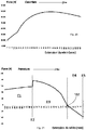
- the Figures 20 and 21 represent a measurement of the resultant force F, applied to the center of gravity 21 of the opening 20 taking into account the gravitational force (acting in the closing direction) and the force produced by the jack attached to the device assistance respectively during the closing and during the opening of the opening.
- the resulting force F is oriented in the direction of the opening. Therefore, it is positive when it moves the opening in the direction of the opening and it is negative when it moves the opening in the direction of closing.
- the resulting force F is represented by an arrow on the figure 16 .
- the resulting force F is measured as a function of the extension of the jack 30.
- An extension of the jack of 0 mm corresponds to the closed position of the opening.
- An extension of the cylinder of 129mm corresponds to the open position of the opening. This value could nevertheless be different for another embodiment.
- the resulting force F does not take into account the effort of a user to open or close the door. If the measurement of the resultant force is positive, a force on the part of the user is necessary to close the opening. If the resultant force measurement is negative, a force from the user is required to open the door.
- step E1 representing the resulting force F applying to the opening during closing
- steps E2, E3, E4 and E5 can be distinguished.
- a first step E1 corresponding to an extension of the jack between 129mm and about 85mm
- the force increases gradually from about 50N to about 60N.
- This step corresponds to the descent of the opening until the support of a cylinder against the cleat.
- a second step E2 the jack comes into contact with the cleat and begins to drive the second structure 120 of the assistance device 100 in rotation.
- the resulting force F increases rapidly from about 60N to about 80N. This increase is due to the pre-charge of the spring 130 when it is in position P1. The load of the spring 130 opposes the closing movement.
- the assistance device progressively moves from the position P1 to the position P2.
- the progressive loading of the spring tends to increase the resultant force.
- the decrease of the angle A1 tends to decrease the resultant force.
- the displacement of the anchor point on the one hand and the load of the spring on the other hand act in a contrary way on the resultant force F.
- the effect of the displacement of the anchor point is greater than the effect of the load of the spring so the assistance device promotes the closing movement during steps E3 and E4.
- step E4 corresponding to an extension of the cylinder of about 29 mm, the force becomes negative: the effect of the force of gravity exceeds the effect the force of the cylinder.
- the closing of the opening thus becomes “automatic” and the opening continues closing course without the user needs to exert effort on it.
- the switching wire 144 stops pressing the jack which causes an inflection point 162 on the curve of the resultant force.
- a fifth step E5 the drive mechanism returns from the driving position P3 to the retracted position P4 with the aid of the drive mechanism against the tooth 150.
- the step E5 is carried out in the last millimeters of extension of the jack, for example in the last or last two millimeters of extension of the jack.
- the height of the tooth can be adjusted to define the position of the cylinder from which step E4 begins.
- the spring 130 then relaxes suddenly which has the effect of restoring the assistance device in the P1 position. The spring is thus successively loaded and unloaded during a single closing movement of the opening. Increasing the angle A1 results in an increase in the resultant force of about 10N.
- the opening ends its closing stroke without reopening.
- the opening can then be locked in the closed position and a new cycle of opening and closing can start again.
- the end of the closing stroke of the opening can therefore be performed without the user need to exert a force on the opening.
- the closed position is thus obtained safely and pleasantly for the user.
- the user is not likely to jam the fingers in the opening by accompanying the closing of the opening to its closed position.
- the user applies to the opening a closure force only in steps E1, E2 and E3, the weight of the opening to achieve the final closing phase of the opening in steps E4 and E5.
- an assistance device and an opening system with automatic opening and partially automatic closure of the opening is entirely mechanical. It does not include connectors or motorization which improves its reliability and simplicity of installation.
- the assistance device can be simply inserted between the body and the actuator cylinder of an opening without questioning the architecture of the vehicle.
- the assistance device can even be installed during a maintenance operation in the after-sales service.
- the opening system could also be adapted so that the assistance device is attached to the opening instead of being fixed to the body.
- the cylinder is advantageously returned so that the non-extensible portion of the jack cooperates with the drive mechanism.
Landscapes
- Power-Operated Mechanisms For Wings (AREA)
Abstract
Description
- La présente invention concerne un dispositif d'assistance pour un ouvrant d'un véhicule automobile. L'invention concerne également un système d'ouverture comprenant un tel dispositif d'assistance. L'invention concerne également un véhicule automobile comprenant un tel dispositif d'assistance ou un tel système d'ouverture.
- L'ouverture d'un ouvrant articulé en rotation selon un axe horizontal requiert une certaine force de la part de l'utilisateur. Lorsque le centre de gravité de l'ouvrant est déplacé vers le haut, l'utilisateur doit supporter le poids de l'ouvrant. Lorsque le centre de gravité de l'ouvrant est déplacé vers le bas, l'utilisateur doit retenir le poids de l'ouvrant pour éviter qu'il descende trop rapidement. On connaît l'utilisation de vérins d'assistance, parfois dénommés « équilibreurs », agencés entre la caisse du véhicule et l'ouvrant. De tels équilibreurs sont capables d'emmagasiner l'énergie fournie par l'ouvrant lors d'une manipulation, par exemple la fermeture de l'ouvrant, et de restituer l'énergie emmagasinée lors d'une autre manipulation, par exemple l'ouverture de l'ouvrant.
- Les équilibreurs peuvent être conçus pour réaliser une ouverture automatique de l'ouvrant, c'est-à-dire sans effort de la part de l'utilisateur sur toute la course de l'ouvrant depuis la position fermée jusqu'à la position ouverte. La fermeture de l'ouvrant requiert alors un effort de l'utilisateur. La phase de fermeture est donc incommode ce qui peut entraîner une mauvaise fermeture ou un mauvais verrouillage de l'ouvrant en position fermée.
- On connaît également l'utilisation de dispositifs d'assistance munis de moteurs électrique pour l'ouverture et/ou la fermeture d'un ouvrant. Toutefois, de tels dispositifs sont complexes, génèrent des surcoûts de fabrication et sont volumineux ce qui rend difficile leur intégration dans un véhicule.
- Le but de l'invention est de fournir un dispositif d'assistance et un système d'ouverture remédiant aux inconvénients ci-dessus et améliorant les dispositifs d'assistance et les systèmes d'ouverture connus de l'art antérieur. En particulier, l'invention permet de réaliser un dispositif d'assistance et un système d'ouverture qui soient simples, pratiques d'utilisation, peu encombrants et fiables.
- L'invention se rapporte à un dispositif d'assistance pour un ouvrant d'un véhicule automobile comprenant :
- une première structure destinée à être fixée à une caisse ou à un ouvrant d'un véhicule automobile, et
- une deuxième structure comprenant un point d'ancrage destiné à être fixé à un vérin d'assistance de la fermeture et/ou de l'ouverture d'un ouvrant, la deuxième structure étant mobile par rapport à la première structure.
- La deuxième structure peut être mobile en rotation autour d'un axe de rotation par rapport à la première structure, le point d'ancrage étant excentré par rapport au dit axe de rotation.
- Le dispositif d'assistance peut comprendre un ressort entre la première structure et la deuxième structure. Le ressort peut être un ressort spiral. Le dispositif d'assistance peut comprendre un moyen de limitation d'une amplitude de déplacement de la deuxième structure par rapport à la première structure, notamment le moyen de limitation de l'amplitude comprenant au moins un pion de guidage solidaire de la deuxième structure coopérant avec au moins un trou oblong dans la première structure.
- Le dispositif d'assistance peut comprendre un mécanisme d'entraînement, fixé sur la deuxième structure, le mécanisme d'entraînement étant muni d'un taquet et le mécanisme d'entraînement pouvant prendre deux positions stables :
- une position d'entraînement dans laquelle le taquet fait saillie de la deuxième structure pour former une butée d'entraînement.
- une position de retrait dans laquelle le taquet est replié le long de la deuxième structure.
- Le mécanisme d'entraînement peut comprendre un fil de commutation contre lequel un appui fait passer le mécanisme d'entraînement de la position de retrait à la position d'entraînement.
- L'invention se rapporte également à un système d'ouverture comprenant :
- une caisse pour véhicule automobile,
- un ouvrant, notamment un hayon, mobile en rotation par rapport à la caisse entre une position ouverte et une position fermée,
- au moins un vérin d'assistance à la fermeture et/ou à l'ouverture de l'ouvrant, et
- au moins un dispositif d'assistance tel que défini précédemment,
- Un appui de l'au moins un vérin contre le taquet du mécanisme d'entraînement peut provoquer le déplacement du point d'ancrage par rapport à la première structure.
- Le système d'ouverture peut comprendre une dent fixée à la caisse de sorte qu'un appui du mécanisme d'entraînement contre la dent fait passer le mécanisme d'entraînement de la position d'entraînement à la position de retrait.
- Le dispositif d'assistance et le vérin peuvent être agencés de sorte que l'ouvrant s'ouvre, sous la seule action du vérin ou de plusieurs vérins, sur une partie ou sur la totalité de la course comprise entre sa position fermée et sa position ouverte.
- Le dispositif d'assistance et le vérin peuvent être agencés de sorte que l'ouvrant s'ouvre, sous la seule action du vérin ou de plusieurs vérins, sur la totalité de la course comprise entre sa position fermée et sa position ouverte, et de sorte que l'ouvrant se ferme, sous la seule action de la force de gravité sur l'ouvrant, sur une partie de la course comprise entre sa position ouverte et sa position fermée.
- L'ouvrant peut être mobile en rotation autour d'un axe d'ouverture, un bras de levier de l'action du vérin sur l'ouvrant diminuant pendant une partie de la course de fermeture et/ou un bras de levier de l'action du vérin sur l'ouvrant augmentant brutalement lorsque l'ouvrant est en position fermée ou dans le voisinage de la position fermée.
- L'au moins un dispositif d'assistance du système d'ouverture peut comprendre un ressort entre la première structure et la deuxième structure, le ressort étant successivement chargé et déchargé au cours d'un même mouvement d'ouverture et/ou de fermeture de l'ouvrant.
- L'invention se rapporte également à un véhicule automobile comprenant au moins un dispositif d'assistance tel que défini précédemment et/ou un système d'ouverture tel que défini précédemment.
- Enfin l'invention se rapporte à un procédé de fonctionnement d'un système d'ouverture et/ou de fermeture d'un ouvrant d'un véhicule automobile, le véhicule comprenant un vérin d'assistance à la fermeture et/ou à l'ouverture de l'ouvrant, le vérin comprenant une première extrémité reliée à une caisse du véhicule, notamment via un dispositif d'assistance, et le vérin comprenant une deuxième extrémité reliée à l'ouvrant, le procédé de fonctionnement comprenant une étape de déplacement de la première extrémité du vérin par rapport à la caisse au cours de l'ouverture et/ou au cours de la fermeture et/ou le procédé de fonctionnement comprenant une étape de déplacement de la deuxième extrémité du vérin par rapport à l'ouvrant au cours de l'ouverture et/ou au cours de la fermeture.
- Ces objets, caractéristiques et avantages de la présente invention seront exposés en détail dans la description suivante d'un mode de réalisation particulier fait à titre non-limitatif en relation avec les figures jointes parmi lesquelles :
- La
figure 1 est une vue schématique d'un véhicule automobile selon un mode de réalisation. - La
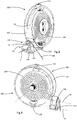
figure 2 est une première vue en perspective d'un dispositif d'assistance selon un mode de réalisation. - La
figure 3 est une deuxième vue en perspective du dispositif d'assistance selon le mode de réalisation. - La
figure 4 est une vue montrant partiellement l'intérieur du dispositif d'assistance selon le mode de réalisation. - La
figure 5 est une vue en perspective partielle du dispositif d'assistance selon le mode de réalisation. - La
figure 6 est une vue en coupe du dispositif d'assistance selon le mode de réalisation, suivant un plan perpendiculaire à son axe. - La
figure 7 est une vue schématique d'un mécanisme d'entraînement, en position d'entraînement, selon un mode de réalisation. - La
figure 8 est une vue schématique du mécanisme d'entraînement, en position de retrait, selon le mode de réalisation. - La
figure 9 est une vue partielle d'un système d'ouverture selon un mode de réalisation, un ouvrant du système d'ouverture étant en position fermée. - La
figure 10 est une vue partielle du système d'ouverture selon le mode de réalisation, l'ouvrant étant dans une première phase d'ouverture. - La
figure 11 est une vue partielle du système d'ouverture selon le mode de réalisation, l'ouvrant étant dans une deuxième phase d'ouverture. - La
figure 12 est une vue partielle du système d'ouverture selon le mode de réalisation, l'ouvrant étant en position ouverte. - La
figure 13 est une vue schématique du système d'ouverture selon le mode de réalisation, l'ouvrant étant en position ouverte. - La
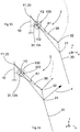
figure 14 est une vue schématique du système d'ouverture selon le mode de réalisation, l'ouvrant étant dans une première phase de fermeture. - La
figure 15 est une vue schématique du système d'ouverture selon le mode de réalisation, l'ouvrant étant dans une deuxième phase de fermeture. - La
figure 16 est une vue schématique du système d'ouverture selon le mode de réalisation, l'ouvrant étant dans une position fermée. - La
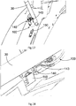
figure 17 est une vue partielle du système d'ouverture selon le mode de réalisation, l'ouvrant étant dans la première phase de fermeture. - La
figure 18 est une vue de détail du système d'ouverture selon le mode de réalisation, l'ouvrant étant dans la deuxième phase de fermeture. - La
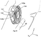
figure 19 est une vue de détail du système d'ouverture selon le mode de réalisation, l'ouvrant étant en position fermée. - La
figure 20 est un graphe de visualisation d'une force résultante sur l'ouvrant en fonction du déplacement d'un vérin, lors de l'ouverture de l'ouvrant. - La
figure 21 est un graphe de visualisation de la force résultante sur l'ouvrant en fonction du déplacement d'un vérin, lors de la fermeture de l'ouvrant. - On définit la gauche et la droite selon le point de vue d'un conducteur d'un véhicule. L'axe X désigne l'axe longitudinal du véhicule. En marche avant et en ligne droite, le véhicule progresse de l'arrière vers l'avant selon une direction parallèle à son axe longitudinal. L'axe X est orienté de l'avant vers l'arrière du véhicule, c'est-à-dire dans le sens de la marche arrière. L'axe Y désigne l'axe transversal du véhicule. L'axe Y est orienté de la gauche vers la droite. L'axe Z désigne l'axe perpendiculaire à l'axe X et à l'axe Y. L'axe Z est un axe vertical lorsque le véhicule repose sur un sol horizontal. L'axe Z est orienté de bas en haut. Les axes X, Y et Z forment un repère orthonormé direct. Sur l'ensemble des figures et de la description, on considère que le véhicule repose sur un sol horizontal. D'autre part, dans un souci de simplification de la description, ce même repère, défini par référence à un véhicule, sera aussi utilisé pour un dispositif d'assistance, même considéré hors d'un véhicule, puisqu'il est destiné à un montage selon une orientation spécifique sur un véhicule.
- La
figure 1 illustre schématiquement un véhicule automobile 1 équipé d'un système d'ouverture 2 selon un mode de réalisation. Le véhicule automobile 1 peut être de n'importe quel type. Par exemple, le véhicule automobile 1 peut être une citadine avec hayon, une berline, un monospace, un SUV (abréviation du terme anglais Sport Utility Vehicle) ou même un véhicule utilitaire. - Le système d'ouverture 2 comprend une caisse 10 du véhicule automobile 1, un ouvrant 20, au moins un vérin 30 pour l'assistance de la fermeture et/ou de l'ouverture de l'ouvrant 20 et au moins un dispositif d'assistance 100 selon un mode de réalisation.
- La caisse 10 est une structure rigide du véhicule automobile 1. Comme on peut notamment le distinguer sur les
figures 9 à 12 , la caisse 10 comprend une traverse 11 arrière de pavillon s'étendant sensiblement transversalement en haut et à l'arrière du véhicule automobile 1. La traverse 11 est prolongée à chaque extrémité par deux montants 12 s'étendant sensiblement verticalement et vers le bas. A leur extrémité inférieure, les deux montants 12 peuvent se rejoindre par l'intermédiaire d'un plancher arrière. Ainsi, la traverse 11, les deux montants 12 et le plancher arrière peuvent définir une ouverture 13 de coffre sur laquelle l'ouvrant 20 peut se refermer. Chaque montant 12 comprend une feuillure 14, autrement dit un renfoncement, accueillant l'ouvrant 20 lorsqu'il est en position fermée. Une telle feuillure 14 peut également servir de gouttière et drainer par exemple l'eau de pluie pour l'évacuer hors du véhicule automobile 1. La feuillure 14 comprend une première face 15 s'étendant selon un plan sensiblement parallèle à l'axe vertical Z et à l'axe longitudinal X et tournée vers l'intérieur du véhicule automobile 1. La feuillure 14 comprend une deuxième face 16 s'étendant selon un plan sensiblement parallèle à l'axe vertical Z et à l'axe transversal Y et tournée vers l'arrière du véhicule. En variante, les montants 12 pourraient avoir toute autre forme. - Dans le mode de réalisation illustré, l'ouvrant 20 est un hayon, autrement dit une porte de coffre. L'ouvrant 20 est mobile par rapport à la caisse 10, entre une position ouverte et une position fermée. L'ouvrant 20 est mobile en rotation autour d'un axe d'ouverture Y1, parallèle à l'axe transversal Y et à la traverse 11 arrière de pavillon. L'ouvrant 20 est rigide et s'étend selon un plan apte à fermer l'ouverture de coffre encadrée par la caisse 10. Sur la
figure 1 , l'ouvrant 20 est représenté en position ouverte. Il s'étend alors sensiblement parallèlement au plan horizontal. En position fermée l'ouvrant 20 est rabattu contre la caisse 10 et s'étend globalement parallèlement à l'axe vertical Z et à l'axe transversal Y. La position fermée de l'ouvrant 20 est représentée notamment sur lesfigures 15 et 16 . L'ouvrant 20 s'ouvre par un mouvement de rotation vers le haut et se ferme par un mouvement de rotation vers le bas. La hauteur du centre de gravité 21 de l'ouvrant 20 en position ouverte est donc plus élevée que la hauteur du centre de gravité de l'ouvrant 20 en position fermée. Avantageusement, la solution pourrait être utilisée pour d'autres ouvrants d'un véhicule pour lesquels la hauteur du centre de gravité varie au cours de l'ouverture ou de la fermeture. - Pour supporter la liaison en rotation de l'ouvrant 20, le système d'ouverture 2 comprend une charnière 22 à une interface entre l'ouvrant 20 et la traverse 11 arrière de pavillon. En outre, le système d'ouverture 2 peut comprendre un dispositif de verrouillage apte à verrouiller l'ouvrant 20 en position fermée.
- Le système d'ouverture 2 peut être symétrique selon un plan médian parallèle à l'axe longitudinal X et parallèle à l'axe vertical Z. Le système d'ouverture 2 comprend alors deux vérins 30 et deux dispositifs d'assistance 100 disposés de part et d'autre de l'ouvrant 20, entre l'ouvrant 20 et chaque montant 12 de la caisse 10. Le système d'ouverture 2 comprend donc d'une part un ensemble gauche comprenant un vérin gauche et un dispositif d'assistance gauche et d'autre part un ensemble droit comprenant un vérin droit et un dispositif d'assistance droit. Ces deux ensembles sont symétriques, aussi nous nous attacherons par la suite à en décrire un en particulier : le vérin gauche et le dispositif d'assistance gauche. En variante le système d'ouverture pourrait ne comporter qu'un seul dispositif d'assistance et un seul vérin ou tout autre nombre de dispositifs d'assistance et de vérins. Le système d'ouverture pourrait également comporter deux vérins de part et d'autre de l'ouvrant mais un seul dispositif d'assistance sur un seul côté.
- Le vérin 30 comprend deux extrémités 31, 32 représentées sur les
figures 13 à 16 : une première extrémité 31 du vérin 30 est fixée au dispositif d'assistance 100, lui-même fixé à la caisse 10, et une deuxième extrémité 32 du vérin 30 est fixée à l'ouvrant 20. Le vérin 30 est un axe extensible formé par un tube intérieur coulissant à l'intérieur d'un tube extérieur. Typiquement, un ordre de grandeur du vérin 30 lorsque l'ouvrant 20 est en position fermée est d'environ 270mm et un ordre de grandeur du vérin 30 lorsque l'ouvrant est en position ouverte est d'environ 400mm. Toutefois ces valeurs pourraient être différentes. Le vérin 30 est muni d'un dispositif élastique (par exemple un ressort ou un gaz sous pression), agencé de sorte qu'il a tendance à exercer une action d'ouverture de l'ouvrant. Le vérin 30 s'oppose donc à la gravité et exerce une poussée sur l'ouvrant 20 orientée dans le sens de l'ouverture. L'effort exercé par le vérin 30 sur l'ouvrant dépend d'une part de la force du dispositif élastique du vérin 30 et d'autre part du positionnement du vérin 30 par rapport à l'ouvrant 20. En particulier, en considérant une projection du système d'ouverture 2 selon l'axe transversal Y telle que représentée sur lesfigures 13 à 16 , on peut définir un angle A1 comme l'angle formé entre l'axe du vérin 30 et l'axe reliant la deuxième extrémité 32 du vérin 30 à l'axe d'ouverture Y1. La projection sur une tangente de la trajectoire de l'ouvrant 20 de la force appliquée par le vérin 30 sur l'ouvrant 20 est proportionnelle à la force du vérin 30 multiplié par le sinus de l'angle A1. Ainsi, plus l'angle A1 est petit, moins le couple mécanique appliqué par le vérin 30 sur l'ouvrant 20 est important, c'est-à-dire moins la force du vérin 30 est efficace pour ouvrir l'ouvrant 20. - Le dispositif d'assistance 100, notamment représenté sur les
figures 2 à 6 , est intercalé entre la première extrémité 31 du vérin 30 et la caisse 10. Plus précisément, il est fixé sur le montant 12, contre la première face 15 de la feuillure 14, en contrebas de la charnière 22 supportant l'ouvrant 20. Le dispositif d'assistance 100 est fixé là où est généralement fixée une première extrémité d'un vérin selon l'état de l'art, c'est-à-dire un vérin directement fixé à la caisse. Le dispositif d'assistance 100 comprend une première structure 110 fixée au montant 12 de la caisse 10 et une deuxième structure 120 fixée à la première extrémité 31 du vérin 30. La première structure 110 et la deuxième structure 120 s'emboîtent l'une dans l'autre et forment ensemble globalement un cylindre dont la base est orientée parallèlement à l'axe vertical Z et à l'axe longitudinal X. La hauteur du cylindre est orientée parallèlement à l'axe transversal Y. Plus généralement, la première structure 110 est liée à la deuxième structure 120 par une liaison mécanique autorisant un degré de liberté, notamment autorisant une rotation, c'est-à-dire une liaison pivot. - La première structure 110, particulièrement visible sur la
figure 3 , comprend un premier disque 111 destiné à être mis en appui contre la première face 15 de la feuillure 14 du montant 12. La première structure 110 comprend également une vis de fixation 112 destinée à maintenir fermement le premier disque 111 contre la caisse 10. Cette vis de fixation 112 traverse une ouverture circulaire 115 au centre du premier disque 111 et coopère avec une ouverture dans la caisse 10. Comme illustré sur lafigure 4 , le premier disque 111 (non visible sur cette figure) est surmonté d'un flanc cylindrique 113 ajouré par deux trous oblongs 114 disposés le long de la circonférence du flanc cylindrique 113. - La deuxième structure 120, particulièrement visible sur les
figures 2 et5 comprend un deuxième disque 121 muni d'une ouverture centrale circulaire au travers de laquelle émerge un troisième disque 117, solidaire de la première structure 110, et muni de deux ouvertures taraudées 116 côte à côte. Le deuxième disque 121 est surmonté d'un flanc cylindrique 122 muni de deux pions de guidage 123 s'étendant radialement et coopérant avec les deux trous oblongs 114 de la première structure. Les deux pions de guidage 123 peuvent être constitués d'une vis 123a traversant le flanc cylindrique et d'un écrou 123b. Le flanc cylindrique 122 de la deuxième structure 120 a un diamètre légèrement supérieur au diamètre du flanc cylindrique 113 de la première structure. Ainsi, La deuxième structure 120 s'emboîte au dessus de la première structure 110. C'est une partie de chaque vis 123a comprise entre le flanc cylindrique 122 et l'écrou 123b qui coopère avec le trou oblong 114 correspondant. Une première face du deuxième disque 121 est tournée vers l'intérieur du dispositif d'assistance, c'est-à-dire vers la première structure et une deuxième face du deuxième disque est tournée vers l'extérieur du dispositif d'assistance. Le deuxième disque 121 comprend un point d'ancrage 124, faisant saillie de la deuxième face du deuxième disque, auquel est fixée la première extrémité 31 du vérin. Ce point d'ancrage est constitué d'une portion de sphère reliée au deuxième disque 121 par un axe perpendiculaire au disque 121. Ainsi la liaison entre le vérin et le dispositif d'assistance est une liaison rotule. Au cours de l'ouverture ou de la fermeture de l'ouvrant, le vérin peut pivoter par rapport au dispositif d'assistance selon un axe parallèle à l'axe transversal Y mais également autour d'axes parallèles à l'axe transversal X et/ou à l'axe vertical Z. Ainsi, le dispositif d'assistance 100 peut être utilisé avec un vérin qui n'est pas tout à fait orienté dans un plan vertical et longitudinal. En variante, cette liaison pourrait être une simple liaison en rotation d'axe parallèle à l'axe transversal Y. Le point d'ancrage est fixé à proximité d'un bord du deuxième disque, proche de la circonférence extérieure du deuxième disque. Le point d'ancrage est donc excentré par rapport au centre du deuxième disque 121. La deuxième structure est mobile en rotation par rapport à la première structure selon un axe Y2 passant par le centre du premier disque 111 de la première structure 110 et par le centre du deuxième disque 121 de la deuxième structure 120. Par conséquent, le point d'ancrage 124, solidaire du disque 121, est également mobile par rapport à la première structure 110. L'axe Y2 est parallèle à l'axe transversal Y. En variante, le dispositif d'assistance pourrait être adapté pour fonctionner avec une liaison glissière entre la première structure et la deuxième structure à la place de cette liaison en rotation. - L'amplitude de la liaison en rotation entre la première et la deuxième structure est limitée par un moyen de limitation d'amplitude. Ce moyen de limitation d'amplitude est obtenu par la butée des deux pions de guidage 123 aux extrémités des deux trous oblongs. L'amplitude de cette liaison peut être par exemple comprise en 45° et 90°. Les deux pions de guidage assurent donc d'une part un maintien de la deuxième structure contre la première structure suivant l'axe transversal Y, et d'autre part la limitation de l'amplitude de la liaison en rotation entre la première structure et la deuxième structure. Grâce au moyen de limitation d'amplitude, on définit la variation du bras de levier de l'action du vérin sur l'ouvrant. Par « bras de levier », on comprend la distance entre le point d'application de la force du vérin sur le dispositif d'assistance et l'axe de rotation Y1. De plus, le ressort 130 ne peut pas être actionné au-delà de ses limites d'élasticité. En variante, le moyen de limitation d'amplitude pourrait ne comprendre qu'un seul pion de guidage coopérant avec un seul trou oblong. Selon une autre variante, le dispositif d'assistance pourrait ne pas comprendre de moyen de limitation d'amplitude, les positions extrêmes du point d'ancrage étant alors simplement établies par un équilibre des forces du vérin sur le dispositif d'assistance lorsque l'ouvrant est en position ouverte ou en position fermée. Le dispositif d'assistance comprend un ressort 130 entre la première structure 110 et la deuxième structure 120, particulièrement visible sur les
figures 4, 5 et6 . Le ressort 130 est un ressort de rappel rappelant la deuxième structure par rapport à la première structure dans une position déterminée relativement à la première structure. Le ressort est à l'intérieur de la forme cylindrique constituée par l'association de la première structure et de la deuxième structure. Le ressort est un ressort spiral. Le ressort spiral comprend une lame métallique enroulée sur elle-même. Une première extrémité 131 de la lame métallique, positionnée vers le centre de la spirale, est fixée à la première structure. Une deuxième extrémité 135 de la lame métallique, positionnée vers l'extérieur de la spirale, est fixée à la deuxième structure. Le ressort spiral comprend six enroulements sur lui-même mais ce nombre pourrait être différent. La raideur du ressort spirale peut être ajustée par exemple par le nombre d'enroulements, l'épaisseur de la lame métallique, la largeur de la lame métallique ou encore par le choix du matériau composant la lame métallique. On peut distinguer deux positions P1, P2 du dispositif d'assistance correspondant aux positions extrêmes de la deuxième structure par rapport à la première structure. Ces deux positions P1, P2 correspondent à la butée des pions de guidage aux deux extrémités des trous oblongs. Dans une première position P1, telle qu'illustrée sur lafigure 6 , le ressort spiral est faiblement chargé. Dans une deuxième position P2, la deuxième structure est pivotée par rapport à la première structure de toute l'amplitude de la liaison en rotation entre les deux structures et le ressort 130 spiral est plus fortement chargé. Le sens de rotation entraînant la charge du ressort est indiqué par une flèche F1 sur lafigure 6 . - La première extrémité 131 du ressort 130 est enserrée entre deux éléments de maintien 132 identiques et positionnés en vis-à-vis, particulièrement visibles sur la
figure 6 . Chaque élément de maintien est vissé sur le troisième disque 117 au moyen d'une vis 133 passant par l'une des deux ouvertures filetées 116. Les éléments de maintien ont la forme d'une portion de disque avec un coté plat et un coté arrondi. L'extrémité de la lame est enserrée entre le coté plat de chaque élément de maintien 132. Le coté circulaire de chaque élément de maintient sert à conformer la lame métallique en donnant à un premier enroulement du ressort spiral une forme circulaire. - La deuxième extrémité 135 comprend un repli à 180° coopérant avec un ergot 125 solidaire de la deuxième structure. L'ergot et le repli sont agencés de sorte que l'ergot retient la deuxième extrémité 132 lorsqu'on fait pivoter la deuxième structure par rapport à la première structure dans le sens de la mise sous tension du ressort spiral.
- Le dispositif d'assistance comprend un mécanisme d'entraînement 140, illustré schématiquement sur les
figures 7 et 8 . Le mécanisme d'entraînement 140 est fixé sur la deuxième structure 120, plus précisément à l'extérieur du flanc 122 cylindrique. Le mécanisme d'entraînement comprend une première plaque 141, une deuxième plaque 142, un taquet 143, un fil de commutation 144 et un ressort de torsion 145. Le mécanisme d'entraînement 140 permet de déplacer la deuxième structure relativement à la première structure contre l'effet du ressort 130 de rappel lors de la fermeture de l'ouvrant. - La première plaque 141 est une pièce plate de forme sensiblement ovale et munie d'un trou circulaire 141a, 141b à chaque extrémité. La première plaque est articulée en rotation par rapport à la deuxième structure autour d'un axe tangentiel T1 passant par un premier trou circulaire 141a. L'axe tangentiel T1 est un axe sensiblement tangent au flanc 122 cylindrique de la deuxième structure. En fonction de la position P1, P2 de la deuxième structure, cet axe tangentiel peut être soit sensiblement parallèle à l'axe longitudinal X, soit sensiblement parallèle à l'axe vertical Z. La deuxième plaque est de forme identique à la première plaque : c'est une pièce plate de forme sensiblement ovale et munie d'un trou circulaire 142a, 142b à chaque extrémité. La deuxième plaque est articulée en rotation par rapport à la première plaque suivant un axe T2 parallèle à l'axe tangentiel T1. A cet effet, un axe traverse le deuxième trou circulaire 141b de la première plaque et le premier trou circulaire 142a de la deuxième plaque. Un élément cylindrique 142c est fixé au niveau du deuxième trou circulaire 142b de la deuxième plaque 142. Cet élément cylindrique 142c est en appui contre le taquet 143. Le taquet 143 est également articulé en rotation par rapport à la deuxième structure autour d'un axe parallèle à l'axe tangentiel T1. Le taquet comprend une ouverture cylindrique supportant l'articulation en rotation du taquet par rapport à la deuxième structure 120 et une surface d'appui 143b apte à prendre appui contre le vérin. Le ressort de torsion 145 permet de mettre en appui l'élément cylindrique 142c contre le taquet 143 quelle que soit la position relative de la deuxième plaque et du taquet. L'appui du taquet contre l'élément cylindrique est orienté en direction de l'axe tangentiel T1. Enfin, le fil de commutation s'étend perpendiculairement à l'axe tangentiel T depuis l'axe T2 traversant le deuxième trou circulaire 141b de la première plaque et le premier trou circulaire 142a de la deuxième plaque.
- Le mécanisme d'entraînement est apte à prendre deux positions P3, P4.
- D'une part le mécanisme d'entraînement peut prendre une position d'entraînement P3, illustrée sur la
figure 7 , dans laquelle le taquet fait saillie de la deuxième structure pour former une butée d'entraînement. Lors de la fermeture de l'ouvrant, le vérin pivote autour du point d'ancrage du dispositif d'assistance et peut venir en contact du taquet, contre la surface d'appui 143b. Le déplacement de déplacement du vérin lors de la fermeture est illustré par une flèche F2 sur lafigure 7 . Le fil de commutation est alors positionné derrière le vérin : il est positionné à l'opposé du vérin par rapport au taquet. - D'autre part le mécanisme d'entraînement peut prendre une position de retrait P4, illustrée sur la
figure 8 , dans laquelle le taquet est replié le long de la deuxième structure. Lors de l'ouverture de l'ouvrant, le vérin pivote autour du point d'ancrage du dispositif d'assistance passe devant le taquet sans le toucher. Par contre, le vérin peut venir en contact du fil de commutation. Le déplacement du vérin lors de la fermeture est illustré par une flèche F3 sur lafigure 8 . La poussée du vérin contre le fil de commutation est transmise à l'axe T2 et a pour effet de faire pivoter la première plaque et la deuxième plaque. L'élément cylindrique 142c de la deuxième plaque appuie sur le taquet 143 qui pivote également. Le mécanisme d'entraînement passe alors de la position de retrait P4 à la position d'entraînement P3. - Grâce à l'effet du ressort de torsion 145, les deux positions P3, P4 du mécanisme d'entraînement sont des positions stables. C'est-à-dire que le mécanisme d'entraînement peut demeurer dans la position P3 ou dans la position P4 en absence d'appuis extérieurs. Un tel mécanisme peut également être dénommé « bistable » par analogie au domaine de l'électronique. D'autres modes de réalisation d'un mécanisme bistable seraient envisageables.
- Le système d'ouverture comprend également une dent 150 fixée à la caisse, plus précisément sur la deuxième face 16 de la feuillure du montant. La dent fait saillie de la deuxième face 16 selon un axe parallèle à l'axe longitudinal X. La dent est positionnée sur la trajectoire du mécanisme d'entraînement lorsque l'on fait tourner la deuxième structure par rapport à la première structure. Plus précisément, la dent est positionnée sur la trajectoire de l'axe traversant le deuxième trou circulaire 141b de la première plaque et le premier trou circulaire 142a de la deuxième plaque, le mécanisme d'entraînement étant dans sa position d'entraînement P3. Un appui de la dent contre l'articulation en rotation entre la première plaque 141 et la deuxième plaque 142 fait passer le mécanisme d'entraînement de la position d'entraînement P3 à la position de retrait P4.
- Nous allons à présent expliquer le fonctionnement du système d'ouverture 2 en observant un mouvement d'ouverture de l'ouvrant 20 suivi d'un mouvement de fermeture de l'ouvrant. La cinématique d'ouverture de l'ouvrant est illustrée en vue tridimensionnelle sur les
figures 9 à 12 . La cinématique de fermeture de l'ouvrant est illustrée de manière schématique sur lesfigures 13 à 16 et en vue tridimensionnelle sur lesfigures 17 à 19 . Sur les vues tridimensionnelles l'ouvrant n'est pas représenté afin de ne pas masquer le dispositif d'assistance 100. - Le concept général de l'invention consiste à déplacer le point d'ancrage 124 de manière faire varier l'efficacité de la poussé du vérin 30. Ainsi, on peut obtenir une ouverture ou une fermeture automatique partielle ou totale.
- La
figure 9 illustre donc le système d'ouverture alors que l'ouvrant est en position fermée. Le vérin est alors positionné le long du montant, à l'intérieur de la feuillure 14. Le mécanisme d'entraînement est dans sa position de retrait P4. Le dispositif d'assistance est dans sa première position P1, c'est-à-dire que le ressort 130 est faiblement chargé. Le point d'ancrage est alors positionné vers le fond de la feuillure de sorte que l'angle A1 est égal ou proche de sa valeur maximale. Dans cette position l'effort de poussée produit par le vérin est optimal. Dès que l'ouvrant est déverrouillé, il passe de manière autonome de la position fermée à la position ouverte. L'ouverture de l'ouvrant est dite « automatique » car l'utilisateur n'a pas besoin d'appliquer d'effort sur l'ouvrant. L'ouverture de l'ouvrant peut donc être réalisée à distance de l'ouvrant si le déverrouillage de l'ouvrant est réalisé grâce à une télécommande. - La
figure 10 illustre le mouvement d'ouverture de l'ouvrant avant que le vérin n'entre en contact avec le fil de commutation 144. Pendant toute la phase d'ouverture, de la position fermée à la position ouverte, le vérin pivote autour du point d'ancrage 124 tout en se déployant. La deuxième structure 120 reste fixe par rapport à la première structure car la poussée du vérin maintient le pion de guidage 123 en butée contre les extrémités respectives des trous oblongs 114. Le dispositif d'assistance est alors dans sa position P1. Le point d'ancrage 124 reste donc fixe par rapport à la caisse. - La
figure 11 illustre le contact du vérin contre le fil de commutation 144. La poussée du vérin contre le fil de commutation 144 fait basculer le mécanisme d'entraînement de la position de retrait P4 à la position d'entraînement P3. Le taquet 143 pivote pour faire saillie de la deuxième structure et passe derrière le vérin. Le vérin étant en train de remonter il n'entre pas en butée contre le taquet. - La
figure 12 illustre le système d'ouverture alors que l'ouvrant est en position ouverte. Le vérin est alors orienté suivant un axe sensiblement parallèle à l'axe longitudinal X et n'est plus en contact avec le taquet. Le vérin reste en contact avec le fil de commutation 144 qui est alors dans une position d'extension maximale par rapport au mécanisme d'entraînement. - Les
figures 13 à 16 illustrent schématiquement l'opération de fermeture de l'ouvrant. Sur lafigure 13 , l'ouvrant est en position ouverte et donc dans la même position que sur lafigure 12 . - La
figure 14 et lafigure 17 illustrent le système d'ouverture lorsque l'ouvrant arrive en contact avec le taquet 143. Le taquet 143 qui était positionné derrière le vérin dans le sens d'ouverture de l'ouvrant est maintenant devant le vérin dans le sens de la fermeture. Le vérin bute donc contre le taquet 143. La butée du vérin contre le taquet bloque le mouvement de rotation du vérin autour du point d'ancrage. La poursuite du mouvement de fermeture au delà du contact du vérin contre le taquet va donc entraîner une rotation de la deuxième structure par rapport à la première structure. La deuxième structure passe donc de la première position P1 à la deuxième position P2, ou une position proche de la position P2. Le ressort 130 va donc se charger progressivement tandis que le point d'ancrage pivote autour de l'axe Y2. Le point d'ancrage étant excentré sur la deuxième structure 120, il se rapproche de l'axe d'ouverture Y1. Le déplacement du point d'ancrage a pour effet d'accentuer la réduction de l'angle A1. Au cours de la fermeture de l'ouvrant, l'angle A1 se réduit d'une part par l'effet de la rotation de l'ouvrant autour de l'axe Y1 et d'autre part par l'effet de la rotation du point d'ancrage 124 autour de l'axe Y2. - La
figure 15 illustre une position de l'ouvrant juste avant la position fermée. Le dispositif d'assistance est alors en position P2 ou proche de la position P2. Le ressort 130 est plus fortement chargé. L'angle A1 atteint une valeur minimale. Juste avant la fermeture complète de l'ouvrant, le mécanisme d'entraînement entre en contact avec la dent 150. La dent appuie sur le mécanisme d'entraînement au niveau de l'articulation en rotation entre la première plaque 141 et la deuxième plaque 142 comme cela est particulièrement visible sur lafigure 18 . Sous l'effet de cet appui la deuxième plaque 142 pivote autour de la première plaque et le mécanisme d'entraînement passe de sa position d'entraînement P3 à sa position de retrait P4. Le taquet n'est alors plus en appui contre le vérin. Le ressort 130 peut alors se détendre et le dispositif d'assistance peut reprendre sa position P1. La fermeture est alors poursuivie jusqu'à la fermeture complète de l'ouvrant, illustrée sur lesfigures 16 et19 . Un nouveau cycle d'ouverture et de fermeture peut alors recommencer. - Les
figures 20 et 21 représentent une mesure de la force résultante F, appliquée sur le centre de gravité 21 de l'ouvrant 20 en prenant en compte la force de gravité (s'exerçant dans le sens de la fermeture) et la force produite par le vérin fixé au dispositif d'assistance respectivement au cours de la fermeture et au cours de l'ouverture de l'ouvrant. La force résultante F est orientée dans le sens de l'ouverture. Par conséquent, elle est positive lorsqu'elle déplace l'ouvrant dans le sens de l'ouverture et elle est négative lorsqu'elle déplace l'ouvrant dans le sens de la fermeture. La force résultante F est représentée par une flèche sur lafigure 16 . La force résultante F est mesurée en fonction de l'extension du vérin 30. Une extension du vérin de 0mm correspond à la position fermée de l'ouvrant. Une extension du vérin de 129mm correspond à la position ouverte de l'ouvrant. Cette valeur pourrait néanmoins être différente pour un autre mode de réalisation. La force résultante F ne tient pas compte de l'effort d'un utilisateur pour ouvrir ou fermer l'ouvrant. Si la mesure de la force résultante est positive, une force de la part de l'utilisateur est nécessaire pour fermer l'ouvrant. Si la mesure de la force résultante est négative, une force de la part de l'utilisateur est nécessaire pour ouvrir l'ouvrant. - Sur la
figure 20 , représentant la force résultante F s'appliquant sur l'ouvrant au cours de l'ouverture, on constate que la force résultante reste positive sur toute la course de l'ouvrant. Dès le début de l'ouverture la force résultante est environ égale à 10N puis monte progressivement jusqu'à environ 60N avant de redescendre à environ 50N en fin de course d'ouverture. - Sur la
figure 21 , représentant la force résultante F s'appliquant sur l'ouvrant au cours de la fermeture, on peut distinguer cinq étapes E1, E2, E3, E4 et E5. Lors d'une première étape E1, correspondant à une extension du vérin compris entre 129mm et environ 85mm, la force augmente progressivement d'environ 50N à environ 60N. Cette étape correspond à la descente de l'ouvrant jusqu'à la mise en appui d'un vérin contre le taquet. - Lors d'une deuxième étape E2, le vérin entre en contact avec le taquet et commence à entraîner la deuxième structure 120 du dispositif d'assistance 100 en rotation. La force résultante F augmente rapidement d'environ 60N à environ 80N. Cette augmentation est due à la pré-charge du ressort 130 lorsqu'il est en position P1. La charge du ressort 130 s'oppose au mouvement de fermeture.
- Lors d'une troisième étape E3 et d'une quatrième étape E4, le dispositif d'assistance passe progressivement de la position P1 à la position P2. La charge progressive du ressort tend à augmenter la force résultante. Par contre, la diminution de l'angle A1 tend à faire diminuer la force résultante. Plus l'angle A1 est faible et plus l'efficacité de l'effort produit par le vérin sur l'ouvrant est faible. Le déplacement du point d'ancrage d'une part et la charge du ressort d'autre part agissent donc de manière contraire sur la force résultante F. Toutefois, l'effet du déplacement du point d'ancrage est supérieur à l'effet de la charge du ressort donc le dispositif d'assistance favorise le mouvement de fermeture lors des étapes E3 et E4. Lors de la quatrième étape E4, correspondant à une extension du vérin d'environ 29mm, l'effort devient négatif : l'effet de la force de gravité dépasse l'effet de la force du vérin. La fermeture de l'ouvrant devient donc « automatique » et l'ouvrant continue sa course de fermeture sans que l'utilisateur n'ait besoin d'exercer un effort dessus. Au début de l'étape E4, le fil de commutation 144 cesse d'appuyer sur le vérin ce qui provoque un point d'inflexion 162 sur la courbe de la force résultante.
- Lors d'une cinquième étape E5, le mécanisme d'entraînement repasse de la position d'entraînement P3 à la position de retrait P4 à la faveur d'un appui du mécanisme d'entraînement contre la dent 150. L'étape E5 est réalisée dans les tous derniers millimètres d'extension du vérin, par exemple dans le dernier ou les deux derniers millimètres d'extension du vérin. La hauteur de la dent peut être ajustée pour définir la position du vérin à partir de laquelle l'étape E4 débute. Le ressort 130 se détend alors brutalement ce qui a pour effet de rétablir le dispositif d'assistance dans la position P1. Le ressort est donc successivement chargé et déchargé au cours d'un même mouvement de fermeture de l'ouvrant. L'augmentation de l'angle A1 entraîne une augmentation de la force résultante qui atteint environ 10N. Grâce à l'inertie acquise par l'ouvrant lors des étapes E3 et E4, l'ouvrant termine sa course de fermeture sans se rouvrir. L'ouvrant peut alors être verrouillé en position fermée et un nouveau cycle d'ouverture et de fermeture peut recommencer. La fin de la course de fermeture de l'ouvrant peut donc s'effectuer sans que l'utilisateur n'ait besoin d'exercer un effort sur l'ouvrant. La position fermée est ainsi obtenue de manière sûre et agréable pour l'utilisateur. Par ailleurs, l'utilisateur ne risque pas de se coincer les doigts dans l'ouvrant en accompagnant la fermeture de l'ouvrant jusqu'à sa position fermée. L'utilisateur applique à l'ouvrant un effort de fermeture uniquement aux étapes E1, E2 et E3, le poids de l'ouvrant permettant de réaliser la phase finale de fermeture de l'ouvrant aux étapes E4 et E5.
- Grâce à l'invention, on dispose d'un dispositif d'assistance et d'un système d'ouverture offrant une ouverture automatique et une fermeture partiellement automatique de l'ouvrant. Le dispositif d'assistance est entièrement mécanique. Il ne comporte pas de connectique ni de motorisation ce qui améliore sa fiabilité et la simplicité d'installation. Le dispositif d'assistance peut être simplement intercalé entre la caisse et le vérin d'assistance d'un ouvrant sans remettre en cause l'architecture du véhicule. Le dispositif d'assistance peut même être installé lors d'une opération de maintenance en après-vente. Lors de l'installation d'un dispositif d'assistance, si la vis 112 est fixée en lieu et place d'un précédent point d'ancrage, la position du nouveau point d'ancrage, lié au dispositif d'assistance, sera décalée de manière à augmenter l'angle A1. Ainsi, un ouvrant dont l'ouverture n'était pas automatique peut être transformé en un ouvrant dont l'ouverture est automatique.
- En variante le système d'ouverture pourrait également être adapté de sorte à ce que le dispositif d'assistance soit fixé à l'ouvrant au lieu d'être fixé à la caisse. Dans ce cas le vérin serait avantageusement retourné pour que la partie non extensible du vérin coopère avec le mécanisme d'entraînement.
Claims (15)
- Dispositif d'assistance (100) pour un ouvrant (20) d'un véhicule automobile (1), caractérisé en ce qu'il comprend :- une première structure (110) destinée à être fixée à une caisse (10) ou à un ouvrant (20) d'un véhicule automobile (1), et- une deuxième structure (120) comprenant un point d'ancrage (124) destiné à être fixé à un vérin (30) d'assistance de la fermeture et/ou de l'ouverture d'un ouvrant (20), la deuxième structure (120) étant mobile par rapport à la première structure (110).
- Dispositif d'assistance (100) selon la revendication précédente, caractérisé en ce que la deuxième structure (120) est mobile en rotation autour d'un axe de rotation (Y2) par rapport à la première structure, le point d'ancrage (124) étant excentré par rapport au dit axe de rotation (Y2).
- Dispositif d'assistance (100) selon l'une des revendications précédentes, caractérisé en ce qu'il comprend un ressort (130) entre la première structure (110) et la deuxième structure (120).
- Dispositif d'assistance (100) selon les revendications 2 et 3, caractérisé en ce que le ressort (130) est un ressort spiral.
- Dispositif d'assistance (100) selon l'une des revendications précédentes, caractérisé en ce qu'il comprend un moyen de limitation d'une amplitude de déplacement de la deuxième structure (120) par rapport à la première structure (110), notamment le moyen de limitation de l'amplitude comprenant au moins un pion de guidage (123) solidaire de la deuxième structure (120) coopérant avec au moins un trou oblong (114) dans la première structure (110).
- Dispositif d'assistance (100) selon l'une des revendications précédentes, caractérisé en ce qu'il comprend un mécanisme d'entraînement (140), fixé sur la deuxième structure (120), le mécanisme d'entraînement (140) étant muni d'un taquet (143) et le mécanisme d'entraînement (140) pouvant prendre deux positions stables :- une position d'entraînement (P3) dans laquelle le taquet (143) fait saillie de la deuxième structure (120) pour former une butée d'entraînement.- une position de retrait (P4) dans laquelle le taquet (143) est replié le long de la deuxième structure (120).
- Dispositif d'assistance (100) selon la revendication précédente, caractérisé en ce que le mécanisme d'entraînement (140) comprend un fil de commutation (144) contre lequel un appui fait passer le mécanisme d'entraînement (140) de la position de retrait (P4) à la position d'entraînement (P3).
- Système d'ouverture (2), caractérisé en ce qu'il comprend :- une caisse (10) pour véhicule (1) automobile,- un ouvrant (20), notamment un hayon, mobile en rotation par rapport à la caisse (10) entre une position ouverte et une position fermée,- au moins un vérin (30) d'assistance à la fermeture et/ou à l'ouverture de l'ouvrant (20), et- au moins un dispositif d'assistance (100) selon l'une des revendications précédentes,la première structure (110) de l'au moins un dispositif d'assistance (100) étant fixée à la caisse (10), la deuxième structure (120) de l'au moins un dispositif d'assistance (100) étant fixée à une première extrémité (31) de l'au moins un vérin (30), une deuxième extrémité (32) de l'au moins un vérin (30) étant fixée à l'ouvrant (20).
- Système d'ouverture (2), caractérisé en ce qu'il comprend :- une caisse (10) pour véhicule (1) automobile,- un ouvrant (20), notamment un hayon, mobile en rotation par rapport à la caisse (10) entre une position ouverte et une position fermée,- au moins un vérin (30) d'assistance à la fermeture et/ou à l'ouverture de l'ouvrant (20), et- un dispositif d'assistance (100) selon l'une des revendications 6 à 7,la première structure (110) de l'au moins un dispositif d'assistance (100) étant fixée à la caisse (10), la deuxième structure (120) de l'au moins un dispositif d'assistance (100) étant fixée à une première extrémité (31) de l'au moins un vérin (30), une deuxième extrémité (32) de l'au moins un vérin (30) étant fixée à l'ouvrant (20), un appui de l'au moins un vérin (30) contre le taquet (143) du mécanisme d'entraînement (140) provoquant le déplacement du point d'ancrage (124) par rapport à la première structure (110).
- Système d'ouverture (2) selon la revendication précédente, caractérisé en ce qu'il comprend une dent (150) fixée à la caisse (10) de sorte qu'un appui du mécanisme d'entraînement (140) contre la dent (150) fait passer le mécanisme d'entraînement (140) de la position d'entraînement (P3) à la position de retrait (P4).
- Système d'ouverture (2) selon l'une des revendications 8 à 10, caractérisé en ce que le dispositif d'assistance (100) et le vérin (30) sont agencés de sorte que l'ouvrant (20) s'ouvre, sous la seule action du vérin (30) ou de plusieurs vérins, sur une partie ou sur la totalité de la course comprise entre sa position fermée et sa position ouverte.
- Système d'ouverture (2) selon l'une des revendications 8 à 11, caractérisé en ce que le dispositif d'assistance (100) et le vérin (30) sont agencés de sorte que l'ouvrant (20) s'ouvre, sous la seule action du vérin (30) ou de plusieurs vérins, sur la totalité de la course comprise entre sa position fermée et sa position ouverte, et de sorte que l'ouvrant (20) se ferme, sous la seule action de la force de gravité sur l'ouvrant, sur une partie de la course comprise entre sa position ouverte et sa position fermée.
- Système d'ouverture (2) selon l'une des revendications 8 à 12 caractérisé en ce que l'ouvrant (20) est mobile en rotation autour d'un axe d'ouverture (Y1), un bras de levier de l'action du vérin (30) sur l'ouvrant (20) diminuant pendant une partie de la course de fermeture et/ou en ce que un bras de levier de l'action du vérin (30) sur l'ouvrant (20) augmente brutalement lorsque l'ouvrant (20) est en position fermée ou dans le voisinage de la position fermée.
- Système d'ouverture (2) selon l'une des revendications 8 à 13 caractérisé en ce que l'au moins un dispositif d'assistance (100) comprend un ressort (130) entre la première structure (110) et la deuxième structure (120), le ressort (130) étant successivement chargé et déchargé au cours d'un même mouvement d'ouverture et/ou de fermeture de l'ouvrant (20).
- Véhicule (1) automobile comprenant au moins un dispositif d'assistance (100) selon l'une des revendications 1 à 7 et/ou un système d'ouverture (2) selon l'une des revendications 8 à 14.
Applications Claiming Priority (1)
| Application Number | Priority Date | Filing Date | Title |
|---|---|---|---|
| FR1760273A FR3072994B1 (fr) | 2017-10-31 | 2017-10-31 | Dispositif d'assistance pour un ouvrant d'un vehicule |
Publications (2)
| Publication Number | Publication Date |
|---|---|
| EP3477030A1 true EP3477030A1 (fr) | 2019-05-01 |
| EP3477030B1 EP3477030B1 (fr) | 2020-12-30 |
Family
ID=61913229
Family Applications (1)
| Application Number | Title | Priority Date | Filing Date |
|---|---|---|---|
| EP18202614.6A Active EP3477030B1 (fr) | 2017-10-31 | 2018-10-25 | Dispositif d'assistance pour un ouvrant d'un véhicule |
Country Status (2)
| Country | Link |
|---|---|
| EP (1) | EP3477030B1 (fr) |
| FR (1) | FR3072994B1 (fr) |
Cited By (1)
| Publication number | Priority date | Publication date | Assignee | Title |
|---|---|---|---|---|
| CN117211628A (zh) * | 2023-09-04 | 2023-12-12 | 浙江零跑科技股份有限公司 | 车门开启机构及车辆 |
Citations (3)
| Publication number | Priority date | Publication date | Assignee | Title |
|---|---|---|---|---|
| US6755458B1 (en) * | 2000-09-29 | 2004-06-29 | Intier Automotive Closures Inc. | Liftgate force control |
| US20040124662A1 (en) * | 2002-09-27 | 2004-07-01 | Cleland Terry P. | Low-mounted powered opening system and control mechanism |
| US20150052704A1 (en) * | 2012-03-14 | 2015-02-26 | Aisin Seiki Kabushiki Kaisha | Opening/closing assistance device for opening/closing device |
-
2017
- 2017-10-31 FR FR1760273A patent/FR3072994B1/fr not_active Expired - Fee Related
-
2018
- 2018-10-25 EP EP18202614.6A patent/EP3477030B1/fr active Active
Patent Citations (3)
| Publication number | Priority date | Publication date | Assignee | Title |
|---|---|---|---|---|
| US6755458B1 (en) * | 2000-09-29 | 2004-06-29 | Intier Automotive Closures Inc. | Liftgate force control |
| US20040124662A1 (en) * | 2002-09-27 | 2004-07-01 | Cleland Terry P. | Low-mounted powered opening system and control mechanism |
| US20150052704A1 (en) * | 2012-03-14 | 2015-02-26 | Aisin Seiki Kabushiki Kaisha | Opening/closing assistance device for opening/closing device |
Cited By (1)
| Publication number | Priority date | Publication date | Assignee | Title |
|---|---|---|---|---|
| CN117211628A (zh) * | 2023-09-04 | 2023-12-12 | 浙江零跑科技股份有限公司 | 车门开启机构及车辆 |
Also Published As
| Publication number | Publication date |
|---|---|
| FR3072994A1 (fr) | 2019-05-03 |
| FR3072994B1 (fr) | 2020-06-26 |
| EP3477030B1 (fr) | 2020-12-30 |
Similar Documents
| Publication | Publication Date | Title |
|---|---|---|
| EP3408478B1 (fr) | Poignee affleurante avec fonction push-pull pour ouvrant de vehicule automobile | |
| EP0150641B1 (fr) | Dispositif d'essuie-glace à mecanisme de changement de longueur efficace de la timonerie, pour l'escamotage du balai en position de repos | |
| EP3477030B1 (fr) | Dispositif d'assistance pour un ouvrant d'un véhicule | |
| WO2013104772A1 (fr) | Bati de montage de portiere de vehicule | |
| FR2876959A1 (fr) | Dispositif d'ouvrant pour vehicule automobile | |
| EP1638797A1 (fr) | Capot de coffre arriere a verrouillage a appui constant, et vehicule ainsi equipe | |
| FR2721649A1 (fr) | Arrêt de porte à deux positions pour véhicule automobile. | |
| EP2990574B1 (fr) | Ensemble arrière de véhicule pour l'ouverture et la fermeture d'un hayon | |
| EP0423040A1 (fr) | Procédé et dispositif de relevage et de dégagement d'une plate-forme normalement horizontale | |
| EP4477435A1 (fr) | Dispositif de gestion de contact pour véhicule automobile à portes antagonistes | |
| FR2705605A1 (fr) | Dispositif de démontage d'une porte de véhicule automobile, par soulèvement axial à l'aide d'un robot. | |
| EP4360926A1 (fr) | Dispositif d'accès comprenant une porte en élytre | |
| WO2024037785A1 (fr) | Dispositif de maintien pour une porte coulissante d'un véhicule automobile | |
| FR3160720A1 (fr) | Dispositif bistable pour la retenue temporaire d’un ouvrant de carrosserie | |
| FR3062629A1 (fr) | Procede de montage de deux portes contigues d'un vehicule automobile | |
| FR2928108A1 (fr) | Dispositif de verrouillage pour toit mobile de vehicule automobile | |
| EP4215701A1 (fr) | Dispositif de commande d'ouverture extérieure | |
| FR2614001A1 (fr) | Berceau de logement pour roue de secours de vehicule | |
| WO2015110737A1 (fr) | Procédé et système d'escamotage de brin boucle de siège de véhicule et véhicule ainsi équipé | |
| FR3140802A1 (fr) | Porte latérale de véhicule automobile | |
| WO2019214928A1 (fr) | Palier d'essuie-glace portant un élément de maintien en position d'un composant de transmission de mouvement | |
| FR2947488A1 (fr) | Dispositif de toit ouvrant a commande manuelle notamment pour vehicule automobile | |
| FR2922826A1 (fr) | Siege de vehicule automobile rabattable vers l'avant | |
| EP3697998A1 (fr) | Dispositif de basculement automatique d'un ouvrant | |
| EP3759300A1 (fr) | Système de verrouillage pour ouvrant, notamment d'un ouvrant de fermeture d'un logement dans l'habitable d'un véhicule automobile |
Legal Events
| Date | Code | Title | Description |
|---|---|---|---|
| PUAI | Public reference made under article 153(3) epc to a published international application that has entered the european phase |
Free format text: ORIGINAL CODE: 0009012 |
|
| STAA | Information on the status of an ep patent application or granted ep patent |
Free format text: STATUS: THE APPLICATION HAS BEEN PUBLISHED |
|
| AK | Designated contracting states |
Kind code of ref document: A1 Designated state(s): AL AT BE BG CH CY CZ DE DK EE ES FI FR GB GR HR HU IE IS IT LI LT LU LV MC MK MT NL NO PL PT RO RS SE SI SK SM TR |
|
| AX | Request for extension of the european patent |
Extension state: BA ME |
|
| STAA | Information on the status of an ep patent application or granted ep patent |
Free format text: STATUS: REQUEST FOR EXAMINATION WAS MADE |
|
| 17P | Request for examination filed |
Effective date: 20191030 |
|
| RBV | Designated contracting states (corrected) |
Designated state(s): AL AT BE BG CH CY CZ DE DK EE ES FI FR GB GR HR HU IE IS IT LI LT LU LV MC MK MT NL NO PL PT RO RS SE SI SK SM TR |
|
| GRAP | Despatch of communication of intention to grant a patent |
Free format text: ORIGINAL CODE: EPIDOSNIGR1 |
|
| STAA | Information on the status of an ep patent application or granted ep patent |
Free format text: STATUS: GRANT OF PATENT IS INTENDED |
|
| INTG | Intention to grant announced |
Effective date: 20200720 |
|
| GRAS | Grant fee paid |
Free format text: ORIGINAL CODE: EPIDOSNIGR3 |
|
| GRAA | (expected) grant |
Free format text: ORIGINAL CODE: 0009210 |
|
| STAA | Information on the status of an ep patent application or granted ep patent |
Free format text: STATUS: THE PATENT HAS BEEN GRANTED |
|
| AK | Designated contracting states |
Kind code of ref document: B1 Designated state(s): AL AT BE BG CH CY CZ DE DK EE ES FI FR GB GR HR HU IE IS IT LI LT LU LV MC MK MT NL NO PL PT RO RS SE SI SK SM TR |
|
| REG | Reference to a national code |
Ref country code: GB Ref legal event code: FG4D Free format text: NOT ENGLISH |
|
| REG | Reference to a national code |
Ref country code: AT Ref legal event code: REF Ref document number: 1350078 Country of ref document: AT Kind code of ref document: T Effective date: 20210115 |
|
| REG | Reference to a national code |
Ref country code: DE Ref legal event code: R096 Ref document number: 602018011280 Country of ref document: DE |
|
| REG | Reference to a national code |
Ref country code: IE Ref legal event code: FG4D Free format text: LANGUAGE OF EP DOCUMENT: FRENCH |
|
| PG25 | Lapsed in a contracting state [announced via postgrant information from national office to epo] |
Ref country code: GR Free format text: LAPSE BECAUSE OF FAILURE TO SUBMIT A TRANSLATION OF THE DESCRIPTION OR TO PAY THE FEE WITHIN THE PRESCRIBED TIME-LIMIT Effective date: 20210331 Ref country code: NO Free format text: LAPSE BECAUSE OF FAILURE TO SUBMIT A TRANSLATION OF THE DESCRIPTION OR TO PAY THE FEE WITHIN THE PRESCRIBED TIME-LIMIT Effective date: 20210330 Ref country code: FI Free format text: LAPSE BECAUSE OF FAILURE TO SUBMIT A TRANSLATION OF THE DESCRIPTION OR TO PAY THE FEE WITHIN THE PRESCRIBED TIME-LIMIT Effective date: 20201230 Ref country code: RS Free format text: LAPSE BECAUSE OF FAILURE TO SUBMIT A TRANSLATION OF THE DESCRIPTION OR TO PAY THE FEE WITHIN THE PRESCRIBED TIME-LIMIT Effective date: 20201230 |
|
| REG | Reference to a national code |
Ref country code: AT Ref legal event code: MK05 Ref document number: 1350078 Country of ref document: AT Kind code of ref document: T Effective date: 20201230 |
|
| PG25 | Lapsed in a contracting state [announced via postgrant information from national office to epo] |
Ref country code: BG Free format text: LAPSE BECAUSE OF FAILURE TO SUBMIT A TRANSLATION OF THE DESCRIPTION OR TO PAY THE FEE WITHIN THE PRESCRIBED TIME-LIMIT Effective date: 20210330 Ref country code: LV Free format text: LAPSE BECAUSE OF FAILURE TO SUBMIT A TRANSLATION OF THE DESCRIPTION OR TO PAY THE FEE WITHIN THE PRESCRIBED TIME-LIMIT Effective date: 20201230 Ref country code: SE Free format text: LAPSE BECAUSE OF FAILURE TO SUBMIT A TRANSLATION OF THE DESCRIPTION OR TO PAY THE FEE WITHIN THE PRESCRIBED TIME-LIMIT Effective date: 20201230 |
|
| REG | Reference to a national code |
Ref country code: NL Ref legal event code: MP Effective date: 20201230 |
|
| PG25 | Lapsed in a contracting state [announced via postgrant information from national office to epo] |
Ref country code: HR Free format text: LAPSE BECAUSE OF FAILURE TO SUBMIT A TRANSLATION OF THE DESCRIPTION OR TO PAY THE FEE WITHIN THE PRESCRIBED TIME-LIMIT Effective date: 20201230 |
|
| REG | Reference to a national code |
Ref country code: LT Ref legal event code: MG9D |
|
| PG25 | Lapsed in a contracting state [announced via postgrant information from national office to epo] |
Ref country code: SK Free format text: LAPSE BECAUSE OF FAILURE TO SUBMIT A TRANSLATION OF THE DESCRIPTION OR TO PAY THE FEE WITHIN THE PRESCRIBED TIME-LIMIT Effective date: 20201230 Ref country code: EE Free format text: LAPSE BECAUSE OF FAILURE TO SUBMIT A TRANSLATION OF THE DESCRIPTION OR TO PAY THE FEE WITHIN THE PRESCRIBED TIME-LIMIT Effective date: 20201230 Ref country code: CZ Free format text: LAPSE BECAUSE OF FAILURE TO SUBMIT A TRANSLATION OF THE DESCRIPTION OR TO PAY THE FEE WITHIN THE PRESCRIBED TIME-LIMIT Effective date: 20201230 Ref country code: LT Free format text: LAPSE BECAUSE OF FAILURE TO SUBMIT A TRANSLATION OF THE DESCRIPTION OR TO PAY THE FEE WITHIN THE PRESCRIBED TIME-LIMIT Effective date: 20201230 Ref country code: RO Free format text: LAPSE BECAUSE OF FAILURE TO SUBMIT A TRANSLATION OF THE DESCRIPTION OR TO PAY THE FEE WITHIN THE PRESCRIBED TIME-LIMIT Effective date: 20201230 Ref country code: PT Free format text: LAPSE BECAUSE OF FAILURE TO SUBMIT A TRANSLATION OF THE DESCRIPTION OR TO PAY THE FEE WITHIN THE PRESCRIBED TIME-LIMIT Effective date: 20210430 |
|
| PG25 | Lapsed in a contracting state [announced via postgrant information from national office to epo] |
Ref country code: AT Free format text: LAPSE BECAUSE OF FAILURE TO SUBMIT A TRANSLATION OF THE DESCRIPTION OR TO PAY THE FEE WITHIN THE PRESCRIBED TIME-LIMIT Effective date: 20201230 Ref country code: PL Free format text: LAPSE BECAUSE OF FAILURE TO SUBMIT A TRANSLATION OF THE DESCRIPTION OR TO PAY THE FEE WITHIN THE PRESCRIBED TIME-LIMIT Effective date: 20201230 |
|
| PG25 | Lapsed in a contracting state [announced via postgrant information from national office to epo] |
Ref country code: IS Free format text: LAPSE BECAUSE OF FAILURE TO SUBMIT A TRANSLATION OF THE DESCRIPTION OR TO PAY THE FEE WITHIN THE PRESCRIBED TIME-LIMIT Effective date: 20210430 |
|
| REG | Reference to a national code |
Ref country code: DE Ref legal event code: R097 Ref document number: 602018011280 Country of ref document: DE |
|
| PG25 | Lapsed in a contracting state [announced via postgrant information from national office to epo] |
Ref country code: IT Free format text: LAPSE BECAUSE OF FAILURE TO SUBMIT A TRANSLATION OF THE DESCRIPTION OR TO PAY THE FEE WITHIN THE PRESCRIBED TIME-LIMIT Effective date: 20201230 Ref country code: AL Free format text: LAPSE BECAUSE OF FAILURE TO SUBMIT A TRANSLATION OF THE DESCRIPTION OR TO PAY THE FEE WITHIN THE PRESCRIBED TIME-LIMIT Effective date: 20201230 |
|
| PLBE | No opposition filed within time limit |
Free format text: ORIGINAL CODE: 0009261 |
|
| STAA | Information on the status of an ep patent application or granted ep patent |
Free format text: STATUS: NO OPPOSITION FILED WITHIN TIME LIMIT |
|
| PG25 | Lapsed in a contracting state [announced via postgrant information from national office to epo] |
Ref country code: DK Free format text: LAPSE BECAUSE OF FAILURE TO SUBMIT A TRANSLATION OF THE DESCRIPTION OR TO PAY THE FEE WITHIN THE PRESCRIBED TIME-LIMIT Effective date: 20201230 |
|
| 26N | No opposition filed |
Effective date: 20211001 |
|
| PG25 | Lapsed in a contracting state [announced via postgrant information from national office to epo] |
Ref country code: ES Free format text: LAPSE BECAUSE OF FAILURE TO SUBMIT A TRANSLATION OF THE DESCRIPTION OR TO PAY THE FEE WITHIN THE PRESCRIBED TIME-LIMIT Effective date: 20201230 |
|
| PG25 | Lapsed in a contracting state [announced via postgrant information from national office to epo] |
Ref country code: SI Free format text: LAPSE BECAUSE OF FAILURE TO SUBMIT A TRANSLATION OF THE DESCRIPTION OR TO PAY THE FEE WITHIN THE PRESCRIBED TIME-LIMIT Effective date: 20201230 |
|
| PG25 | Lapsed in a contracting state [announced via postgrant information from national office to epo] |
Ref country code: IS Free format text: LAPSE BECAUSE OF FAILURE TO SUBMIT A TRANSLATION OF THE DESCRIPTION OR TO PAY THE FEE WITHIN THE PRESCRIBED TIME-LIMIT Effective date: 20210430 |
|
| REG | Reference to a national code |
Ref country code: CH Ref legal event code: PL |
|
| REG | Reference to a national code |
Ref country code: BE Ref legal event code: MM Effective date: 20211031 |
|
| PG25 | Lapsed in a contracting state [announced via postgrant information from national office to epo] |
Ref country code: MC Free format text: LAPSE BECAUSE OF FAILURE TO SUBMIT A TRANSLATION OF THE DESCRIPTION OR TO PAY THE FEE WITHIN THE PRESCRIBED TIME-LIMIT Effective date: 20201230 |
|
| PG25 | Lapsed in a contracting state [announced via postgrant information from national office to epo] |
Ref country code: LU Free format text: LAPSE BECAUSE OF NON-PAYMENT OF DUE FEES Effective date: 20211025 Ref country code: BE Free format text: LAPSE BECAUSE OF NON-PAYMENT OF DUE FEES Effective date: 20211031 |
|
| PG25 | Lapsed in a contracting state [announced via postgrant information from national office to epo] |
Ref country code: LI Free format text: LAPSE BECAUSE OF NON-PAYMENT OF DUE FEES Effective date: 20211031 Ref country code: CH Free format text: LAPSE BECAUSE OF NON-PAYMENT OF DUE FEES Effective date: 20211031 |
|
| PG25 | Lapsed in a contracting state [announced via postgrant information from national office to epo] |
Ref country code: IE Free format text: LAPSE BECAUSE OF NON-PAYMENT OF DUE FEES Effective date: 20211025 |
|
| PG25 | Lapsed in a contracting state [announced via postgrant information from national office to epo] |
Ref country code: NL Free format text: LAPSE BECAUSE OF NON-PAYMENT OF DUE FEES Effective date: 20201230 Ref country code: CY Free format text: LAPSE BECAUSE OF FAILURE TO SUBMIT A TRANSLATION OF THE DESCRIPTION OR TO PAY THE FEE WITHIN THE PRESCRIBED TIME-LIMIT Effective date: 20201230 |
|
| P01 | Opt-out of the competence of the unified patent court (upc) registered |
Effective date: 20230608 |
|
| PG25 | Lapsed in a contracting state [announced via postgrant information from national office to epo] |
Ref country code: SM Free format text: LAPSE BECAUSE OF FAILURE TO SUBMIT A TRANSLATION OF THE DESCRIPTION OR TO PAY THE FEE WITHIN THE PRESCRIBED TIME-LIMIT Effective date: 20201230 Ref country code: HU Free format text: LAPSE BECAUSE OF FAILURE TO SUBMIT A TRANSLATION OF THE DESCRIPTION OR TO PAY THE FEE WITHIN THE PRESCRIBED TIME-LIMIT; INVALID AB INITIO Effective date: 20181025 |
|
| PG25 | Lapsed in a contracting state [announced via postgrant information from national office to epo] |
Ref country code: MK Free format text: LAPSE BECAUSE OF FAILURE TO SUBMIT A TRANSLATION OF THE DESCRIPTION OR TO PAY THE FEE WITHIN THE PRESCRIBED TIME-LIMIT Effective date: 20201230 |
|
| PG25 | Lapsed in a contracting state [announced via postgrant information from national office to epo] |
Ref country code: TR Free format text: LAPSE BECAUSE OF FAILURE TO SUBMIT A TRANSLATION OF THE DESCRIPTION OR TO PAY THE FEE WITHIN THE PRESCRIBED TIME-LIMIT Effective date: 20201230 |
|
| PG25 | Lapsed in a contracting state [announced via postgrant information from national office to epo] |
Ref country code: MT Free format text: LAPSE BECAUSE OF FAILURE TO SUBMIT A TRANSLATION OF THE DESCRIPTION OR TO PAY THE FEE WITHIN THE PRESCRIBED TIME-LIMIT Effective date: 20201230 |
|
| PGFP | Annual fee paid to national office [announced via postgrant information from national office to epo] |
Ref country code: DE Payment date: 20251021 Year of fee payment: 8 |
|
| PGFP | Annual fee paid to national office [announced via postgrant information from national office to epo] |
Ref country code: GB Payment date: 20251022 Year of fee payment: 8 |
|
| PGFP | Annual fee paid to national office [announced via postgrant information from national office to epo] |
Ref country code: FR Payment date: 20251030 Year of fee payment: 8 |