EP3476992A1 - Washing machine - Google Patents
Washing machine Download PDFInfo
- Publication number
- EP3476992A1 EP3476992A1 EP17198630.0A EP17198630A EP3476992A1 EP 3476992 A1 EP3476992 A1 EP 3476992A1 EP 17198630 A EP17198630 A EP 17198630A EP 3476992 A1 EP3476992 A1 EP 3476992A1
- Authority
- EP
- European Patent Office
- Prior art keywords
- washing machine
- water
- pipes
- pipe
- machine according
- Prior art date
- Legal status (The legal status is an assumption and is not a legal conclusion. Google has not performed a legal analysis and makes no representation as to the accuracy of the status listed.)
- Granted
Links
Images


Classifications
-
- D—TEXTILES; PAPER
- D06—TREATMENT OF TEXTILES OR THE LIKE; LAUNDERING; FLEXIBLE MATERIALS NOT OTHERWISE PROVIDED FOR
- D06F—LAUNDERING, DRYING, IRONING, PRESSING OR FOLDING TEXTILE ARTICLES
- D06F39/00—Details of washing machines not specific to a single type of machines covered by groups D06F9/00 - D06F27/00
- D06F39/08—Liquid supply or discharge arrangements
- D06F39/088—Liquid supply arrangements
-
- D—TEXTILES; PAPER
- D06—TREATMENT OF TEXTILES OR THE LIKE; LAUNDERING; FLEXIBLE MATERIALS NOT OTHERWISE PROVIDED FOR
- D06F—LAUNDERING, DRYING, IRONING, PRESSING OR FOLDING TEXTILE ARTICLES
- D06F2103/00—Parameters monitored or detected for the control of domestic laundry washing machines, washer-dryers or laundry dryers
- D06F2103/02—Characteristics of laundry or load
- D06F2103/04—Quantity, e.g. weight or variation of weight
-
- D—TEXTILES; PAPER
- D06—TREATMENT OF TEXTILES OR THE LIKE; LAUNDERING; FLEXIBLE MATERIALS NOT OTHERWISE PROVIDED FOR
- D06F—LAUNDERING, DRYING, IRONING, PRESSING OR FOLDING TEXTILE ARTICLES
- D06F2103/00—Parameters monitored or detected for the control of domestic laundry washing machines, washer-dryers or laundry dryers
- D06F2103/18—Washing liquid level
-
- D—TEXTILES; PAPER
- D06—TREATMENT OF TEXTILES OR THE LIKE; LAUNDERING; FLEXIBLE MATERIALS NOT OTHERWISE PROVIDED FOR
- D06F—LAUNDERING, DRYING, IRONING, PRESSING OR FOLDING TEXTILE ARTICLES
- D06F2103/00—Parameters monitored or detected for the control of domestic laundry washing machines, washer-dryers or laundry dryers
- D06F2103/38—Time, e.g. duration
-
- D—TEXTILES; PAPER
- D06—TREATMENT OF TEXTILES OR THE LIKE; LAUNDERING; FLEXIBLE MATERIALS NOT OTHERWISE PROVIDED FOR
- D06F—LAUNDERING, DRYING, IRONING, PRESSING OR FOLDING TEXTILE ARTICLES
- D06F2103/00—Parameters monitored or detected for the control of domestic laundry washing machines, washer-dryers or laundry dryers
- D06F2103/68—Operation mode; Programme phase
-
- D—TEXTILES; PAPER
- D06—TREATMENT OF TEXTILES OR THE LIKE; LAUNDERING; FLEXIBLE MATERIALS NOT OTHERWISE PROVIDED FOR
- D06F—LAUNDERING, DRYING, IRONING, PRESSING OR FOLDING TEXTILE ARTICLES
- D06F2105/00—Systems or parameters controlled or affected by the control systems of washing machines, washer-dryers or laundry dryers
- D06F2105/02—Water supply
-
- D—TEXTILES; PAPER
- D06—TREATMENT OF TEXTILES OR THE LIKE; LAUNDERING; FLEXIBLE MATERIALS NOT OTHERWISE PROVIDED FOR
- D06F—LAUNDERING, DRYING, IRONING, PRESSING OR FOLDING TEXTILE ARTICLES
- D06F2105/00—Systems or parameters controlled or affected by the control systems of washing machines, washer-dryers or laundry dryers
- D06F2105/06—Recirculation of washing liquids, e.g. by pumps or diverting valves
-
- D—TEXTILES; PAPER
- D06—TREATMENT OF TEXTILES OR THE LIKE; LAUNDERING; FLEXIBLE MATERIALS NOT OTHERWISE PROVIDED FOR
- D06F—LAUNDERING, DRYING, IRONING, PRESSING OR FOLDING TEXTILE ARTICLES
- D06F33/00—Control of operations performed in washing machines or washer-dryers
- D06F33/30—Control of washing machines characterised by the purpose or target of the control
- D06F33/32—Control of operational steps, e.g. optimisation or improvement of operational steps depending on the condition of the laundry
- D06F33/34—Control of operational steps, e.g. optimisation or improvement of operational steps depending on the condition of the laundry of water filling
-
- D—TEXTILES; PAPER
- D06—TREATMENT OF TEXTILES OR THE LIKE; LAUNDERING; FLEXIBLE MATERIALS NOT OTHERWISE PROVIDED FOR
- D06F—LAUNDERING, DRYING, IRONING, PRESSING OR FOLDING TEXTILE ARTICLES
- D06F33/00—Control of operations performed in washing machines or washer-dryers
- D06F33/50—Control of washer-dryers characterised by the purpose or target of the control
- D06F33/52—Control of the operational steps, e.g. optimisation or improvement of operational steps depending on the condition of the laundry
- D06F33/54—Control of the operational steps, e.g. optimisation or improvement of operational steps depending on the condition of the laundry of water filling
Definitions
- the present disclosure relates to a washing machine
- Washing machines are used for washing washable items, including garments such as clothes. Typically a user can select a suitable washing cycle via an interface on a front face of the washing machine.
- the interface usually includes a number of control knobs and/or buttons.
- Some washing machines have both washing and drying functionality. Such machines may be known as washer-dryers.
- a washing machine comprising: a water inlet constructed and arranged to supply water to the washing machine; a pipe arrangement comprising two or more pipes, the pipe arrangement located between the water inlet and a component of the washing machine, each of the two or more pipes having a respective inlet valve, and each of the two or more pipes being of a different diameter; and a controller, the controller configured to control the inlet valves of the two or more pipes so as to selectively allow water to flow through one or more of the two or more pipes, to control a flow rate of water to the component.
- each of the two or more pipes of the pipe arrangement is of the same length.
- the two or more pipes of the pipe arrangement are arranged one above the other in the washing machine.
- a first pipe of the two or more pipes having a first diameter and a second pipe of the two or more pipes having a second diameter, the first diameter being larger than the second diameter, the second pipe being arranged above the first pipe.
- the two or more pipes of the pipe arrangement are arranged in parallel.
- the washing machine comprises a water tank located between the water inlet and the pipe arrangement.
- the water tank comprises a float switch, the float switch constructed and arranged to inform the controller of a water level in the water tank.
- the washing machine comprises a pump located between the water tank and the pipe arrangement.
- the controller is configured to control the pump so as to deliver water to an entrance of the pipe arrangement at a predetermined pressure.
- the controller is configured to control the flow rate of water to the component in dependence on one or more parameters.
- the one or more parameters comprises one or more of: a stage of a washing cycle; a type of washing cycle; a weight of a washing load.
- the component comprises a drum of the washing machine.
- the component comprises a dispenser of the washing machine.
- the dispenser comprises a detergent dispenser and/or a fabric softener dispenser.
- the present disclosure has applicability to clothes washing machines.
- a user places a washing load comprising one or more items to be washed and/or dried in to a drum of the washing machine.
- the user then typically selects a washing cycle from a variety of available washing cycles via a user interface of the washing machine.
- the items may include garments such as clothes.
- the items may also include bedsheets, pillowcases, shoes etc.
- one or more washing additives may be added to the drum of the washing machine so as to enhance the wash.
- the washing additive(s) may comprise, for example, washing detergent and/or fabric softener.
- the washing additive(s) may be added to the drum via one or more respective dispenser(s).
- water is fed to a drum of the washing machine.
- the amount or flow rate of water that needs to be delivered to the drum may vary.
- one or more devices may be used to measure the water flow rate, so that it can be controlled.
- Such a device may comprise an encoder.
- encoders can become damaged in the washing machine, for example after being subjected to high water pressure and/or electronic malfunction. If the encoder is damaged then a volume and/or flow rate of water delivered to the drum may be incorrect. If too little water is delivered then the washing load may be insufficiently cleaned. On the other hand, if too much water is delivered to the drum then this may result in damage to the machine and/or flooding.
- FIG. 1 schematically shows a washing machine 102 according to an example.
- the washing machine 102 comprises a main body portion 104 and a drum 106 which is arranged to hold one or more garments or items of a washing load to be washed.
- a washing additive may be added for enhancement of the wash.
- the washing additive may comprise washing detergent.
- the washing additive may additionally or alternatively include any one or more (or indeed any combination of): fabric softener, soda crystals, limescale remover, water etc.
- the additive may be in a liquid or a powder form.
- one or more dispensers or containers are provided for containing such an additive or additives.
- a dispenser 112 is provided for receiving washing detergent.
- a dispenser 114 is provided for receiving fabric softener
- a user interface 108 is provided which enables a user to select one or more washing and/or drying parameters and/or settings.
- a display 110 is also provided which outputs information to a user of the washing machine. For example, information displayed on the display 110 may be information regarding options selected via user interface 108, and/or information regarding a washing cycle in progress such as time remaining etc.
- the washing machine 102 also comprises a controller shown schematically at 130.
- the controller 130 is arranged for controlling operations of the washing machine 102.
- the washing machine 102 also comprises a suitable power connection, shown schematically at 120, enabling the washing machine 102 to be connected to an electricity supply such as mains electricity.
- the washing machine 102 further comprises a water inlet shown schematically at 116.
- the water inlet 116 may receive water from a mains water supply, for example.
- a water outlet is shown schematically at 118.
- the water outlet may, for example, send waste water from the washing machine 102 to a waste water pipe, as is known.
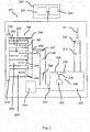
- FIG. 2 schematically shows certain parts of a washing machine 202 according to an example.
- the example enables a flow rate of water to a component (e.g. washing machine drum and/or dispenser) of the washing machine to be controlled in a reliable manner.
- a component e.g. washing machine drum and/or dispenser
- the washing machine 202 comprises a controller 230.
- the controller 230 comprises a memory 232 and a processor 234.
- the controller is operable to control aspects of the washing machine 202.
- the controller may communicate with one or more pumps, valves, switches etc. as will be explained in more detail below.
- the washing machine comprises a water tank 222.
- Water schematically shown by arrow 221, can be fed to water tank 222 via inlet 216.
- Valve 219 may be selectively moved between open and closed positions so as to control the flow of water in to the tank 222.
- a switch arrangement generally shown at 224 is provided.
- the switch 224 is operable to inform the controller 230 of a level of water in the tank 222.
- the switch arrangement 224 informs the controller 230 when the level of water in the tank has reached a threshold level.
- the threshold level is when the tank is full.
- the controller 230 can cause closure of valve 219 so as to prevent more water from entering the tank 222 (or backing up in the upstream pipework).
- the switch arrangement 224 comprises a float switch arrangement.
- the float switch arrangement comprises float 226 to which a switch element 228 is attached.
- the switch element 228 contacts electrical connectors 236 and 238 so as to complete an electrical circuit.
- An electrical signal is then sent to the controller 230 to inform the controller 230 that the level of water in the tank 222 has reached the threshold level.
- This arrangement may be useful for maintaining a constant and/or known water pressure.
- a washing machine component is shown at 270.
- the washing machine component comprises a drum of the washing machine.
- the component 270 comprises a dispenser (e.g. a dispenser of detergent or fabric softener).
- the washing machine 202 is arranged to deliver water from the inlet 216 to the component 270, in this example via water tank 222.
- the washing machine 202 is arranged to deliver water from the water tank 222 to the component 270 via one or more other components.
- the washing machine 202 may be arranged to deliver water from the water tank 222 to a drum of the washing machine via a dispenser.
- a pipe arrangement or network is shown at 246.
- the pipe arrangement 246 is in fluid communication with inlet 216.
- the pipe arrangement 246 is in fluid communication with inlet 216 via water tank 222.
- Pipe arrangement 246 is in fluid communication with water tank 222 via pipe 245.
- a valve 240 is controllable between open and closed positions to allow water to flow from water tank 222 to pipe arrangement 246, via pipe 245.
- a pump 242 is provided.
- the pump 242 pumps water, as schematically shown by arrow 244, to an entrance 247 of pipe arrangement 246.
- the water pressure is at a constant or known value. That is it may be considered that the controller can control the pump so as to deliver water to an entrance 247 of the pipe arrangement at a determined or predetermined pressure.
- the pipe arrangement is in fluid communication with component 270. That is the pipe arrangement 246 may be considered to comprise an upstream side connected to water tank 222, and a downstream side connected to component 270.
- the pipe arrangement 246 comprises two or more pipes. In some examples more than two pipes may be provided. In the example of Figure 2 five pipes are provided, namely first pipe 248, second pipe 250, third pipe 252, fourth pipe 254, and fifth pipe 256. In examples, each of the two or more pipes are vertically arranged, one above the other. Each of the pipes is of a different diameter. More specifically, each of the pipes has a different inner diameter (and may have a different or the same outer diameter). Accordingly each pipe has a different cross-sectional flow area. In some examples the pipe having the smallest diameter is placed at the top of a vertically arranged stack of pipes forming the pipe arrangement 246, and the pipe having the largest diameter is placed at the bottom of the vertically arranged stack of pipes forming the pipe arrangement 246.
- the water pressure at an entrance of the pipe of the smallest diameter may (e.g. at valve 258) be lower than a water pressure at an entrance of the pipe of the largest diameter (e.g. at valve 266).
- pipes 248 to 256 may be considered to have respective diameters dl to d5, where d1 ⁇ d2 ⁇ d3 ⁇ d4 ⁇ d5.
- the inlet pipe 216 has a diameter d6.
- the diameter (i.e. inner diameter) of the inlet pipe 216 is greater than the diameters (i.e. inner diameters) of any of the pipes 248 to 256 in the pipe arrangement 246.
- each pipe in the pipe arrangement 246 is of the same length.
- Each pipe in the pipe arrangement comprises a respective inlet valve.
- pipe 248 comprises inlet valve 258, pipe 250 comprises inlet valve 260, pipe 252 comprises inlet valve 262, pipe 254 comprises inlet valve 264, and pipe 256 comprises inlet valve 266.
- Each of inlet valves 258 to 266 is individually controllable by controller 230.
- the controller 230 is configured to selectively allow water to flow through one or more of the two or more pipes by controlling the inlet valves of the two or more pipes, so as to control a flow rate of water to the component 270.
- Water flow through the pipes 248 to 256 is schematically shown by the block arrows in the respective pipes.
- the controller 230 is configured to control water flow-rate to component 270 by controlling which pipes in the pipe arrangement 246 water is able to flow through.
- the flow-rate may be considered a volume of water delivered over time.
- the flow rate may be in the units m 3 /s (cubic metres per second).
- each of valves 258, 260, 262 and 264 may be closed, with valve 266 being opened.
- water pumped from water tank 222 can pass through pipe 256 at a relatively high flow rate to component 270, since pipe 256 has the largest diameter of each of the pipes in the pipe arrangement 246.
- valves 260, 262, 264 and 266 may be closed, with valve 258 being opened.
- water pumped from water tank 222 can pass through pipe 248 at a relatively low flow rate to component 270, since pipe 248 has the smallest diameter of each of the pipes in the pipe arrangement 246.
- More than one of valves 258, 260, 262, 264 and 266 could be open at the same time, and in any combination. For example if it is determined that, with valve 266 open and water flowing through pipe 256 that slightly more water is required at component 270, then valve 258 could also be opened so as to supply an additional flow rate of water to component 270 via pipe 248 (i.e.
- any other combination of open and closed pipes in pipe arrangement 246 is envisaged alone or in combination. Where flow is permitted through two or more pipes in the pipe arrangement 246 simultaneously, then the respective valves to those pipes may be opened simultaneously or in sequence. In some situations all of the pipes in pipe arrangement 246 may be open for flow. This may occur, for example, where a maximum possible flow rate is required, for example in an initial soak stage where it may be deemed desirable to soak the washing load as quickly as possible. Of course, in some situations all of the pipes in the pipe arrangement may be closed for flow.
- the controller 230 is configured to control a flow rate of water to the component 270 in dependence on one or more parameters.
- the one or more parameters may be, for example, a stage of a washing cycle (e.g. soak, spin etc).
- the one or more parameters may additionally or alternatively be a type of washing cycle.
- the type of washing cycle may be dependent on a type of item or items in the washing load.
- the type of washing cycle may be a cottons washing cycle, a delicates washing cycle etc.
- the one or more parameters may alternatively or additionally comprise a determined weight of the washing load.
- the controller 230 is also operable to control valves 218 and 240, so as to control flow of water in to and out of water tank 222. This may enable the controller to prevent a build-up of excessive water pressure in the system, for example in pipe 245.
- Figure 3 is a flow chart showing a method according to an example. The method may be, for example, carried out in controller 230.
- the main valve 218 to the tank 222 is opened, so as to enable water to flow in to tank 222.
- the method then loops back to S2. Therefore in some examples it may be considered that a level of water in tank 222 is continuously monitored.
- the controller determines which pipes in pipe arrangement 246 to open for water flow. As discussed above, this determination may be based on one or more parameters.
- valves 240, 258, 260, 262, 264, 266 the necessary pipe valve(s) are opened (e.g. one or more of valves 240, 258, 260, 262, 264, 266), and pump 242 is driven so as to pump water to pipe arrangement 246.
- the operation may be, for example, the washing cycle or stage of a washing cycle requiring water.
- the open valve(s) can be closed as required, and the pump 242 switched off or put in to an idle state.
- processor or processing system or circuitry referred to herein may in practice be provided by a single chip or integrated circuit or plural chips or integrated circuits, optionally provided as a chipset, an application-specific integrated circuit (ASIC), field-programmable gate array (FPGA), digital signal processor (DSP), graphics processing units (GPUs), etc.
- the chip or chips may comprise circuitry (as well as possibly firmware) for embodying at least one or more of a data processor or processors, a digital signal processor or processors, baseband circuitry and radio frequency circuitry, which are configurable so as to operate in accordance with the exemplary embodiments.
- the exemplary embodiments may be implemented at least in part by computer software stored in (non-transitory) memory and executable by the processor, or by hardware, or by a combination of tangibly stored software and hardware (and tangibly stored firmware).
- the invention also extends to computer programs, particularly computer programs on or in a carrier, adapted for putting the invention into practice.
- the program may be in the form of non-transitory source code, object code, a code intermediate source and object code such as in partially compiled form, or in any other non-transitory form suitable for use in the implementation of processes according to the invention.
- the carrier may be any entity or device capable of carrying the program.
- the carrier may comprise a storage medium, such as a solid-state drive (SSD) or other semiconductor-based RAM; a ROM, for example a CD ROM or a semiconductor ROM; a magnetic recording medium, for example a floppy disk or hard disk; optical memory devices in general; etc.
- SSD solid-state drive
- ROM read-only memory
- magnetic recording medium for example a floppy disk or hard disk
- optical memory devices in general etc.
Landscapes
- Engineering & Computer Science (AREA)
- Textile Engineering (AREA)
- Control Of Washing Machine And Dryer (AREA)
- Detail Structures Of Washing Machines And Dryers (AREA)
Abstract
Description
- The present disclosure relates to a washing machine
- Washing machines are used for washing washable items, including garments such as clothes. Typically a user can select a suitable washing cycle via an interface on a front face of the washing machine. The interface usually includes a number of control knobs and/or buttons. Some washing machines have both washing and drying functionality. Such machines may be known as washer-dryers.
- According to a first aspect disclosed herein, there is provided a washing machine comprising: a water inlet constructed and arranged to supply water to the washing machine; a pipe arrangement comprising two or more pipes, the pipe arrangement located between the water inlet and a component of the washing machine, each of the two or more pipes having a respective inlet valve, and each of the two or more pipes being of a different diameter; and a controller, the controller configured to control the inlet valves of the two or more pipes so as to selectively allow water to flow through one or more of the two or more pipes, to control a flow rate of water to the component.
- According to an example, each of the two or more pipes of the pipe arrangement is of the same length.
- According to an example, the two or more pipes of the pipe arrangement are arranged one above the other in the washing machine.
- According to an example, a first pipe of the two or more pipes having a first diameter and a second pipe of the two or more pipes having a second diameter, the first diameter being larger than the second diameter, the second pipe being arranged above the first pipe.
- According to an example, the two or more pipes of the pipe arrangement are arranged in parallel.
- According to an example, the washing machine comprises a water tank located between the water inlet and the pipe arrangement.
- According to an example, the water tank comprises a float switch, the float switch constructed and arranged to inform the controller of a water level in the water tank.
- According to an example, the washing machine comprises a pump located between the water tank and the pipe arrangement.
- According to an example, the controller is configured to control the pump so as to deliver water to an entrance of the pipe arrangement at a predetermined pressure.
- According to an example, the controller is configured to control the flow rate of water to the component in dependence on one or more parameters.
- According to an example, the one or more parameters comprises one or more of: a stage of a washing cycle; a type of washing cycle; a weight of a washing load.
- According to an example, the component comprises a drum of the washing machine.
- According to an example, the component comprises a dispenser of the washing machine.
- According to an example, the dispenser comprises a detergent dispenser and/or a fabric softener dispenser.
- To assist understanding of the present disclosure and to show how embodiments may be put into effect, reference is made by way of example to the accompanying drawings in which:
-
Figure 1 shows schematically a washing machine according to an example. -
Figure 2 shows schematically some aspects of a washing machine according to an example. -
Figure 3 is a flow-chart of a method according to an example. - The present disclosure has applicability to clothes washing machines.
- Before a washing cycle begins a user places a washing load comprising one or more items to be washed and/or dried in to a drum of the washing machine. The user then typically selects a washing cycle from a variety of available washing cycles via a user interface of the washing machine. The items may include garments such as clothes. The items may also include bedsheets, pillowcases, shoes etc. Before or during commencement of a washing cycle, one or more washing additives may be added to the drum of the washing machine so as to enhance the wash. The washing additive(s) may comprise, for example, washing detergent and/or fabric softener. The washing additive(s) may be added to the drum via one or more respective dispenser(s). During a washing cycle water is fed to a drum of the washing machine. Dependent on a stage of the washing cycle or another parameter (e.g. a determined size or type of the washing load), the amount or flow rate of water that needs to be delivered to the drum may vary. In some conventional washing machines, one or more devices may be used to measure the water flow rate, so that it can be controlled. Such a device may comprise an encoder. Sometimes, such encoders can become damaged in the washing machine, for example after being subjected to high water pressure and/or electronic malfunction. If the encoder is damaged then a volume and/or flow rate of water delivered to the drum may be incorrect. If too little water is delivered then the washing load may be insufficiently cleaned. On the other hand, if too much water is delivered to the drum then this may result in damage to the machine and/or flooding.
-
Figure 1 schematically shows awashing machine 102 according to an example. Thewashing machine 102 comprises amain body portion 104 and adrum 106 which is arranged to hold one or more garments or items of a washing load to be washed. - Before or during a washing cycle, a washing additive may be added for enhancement of the wash. The washing additive may comprise washing detergent. The washing additive may additionally or alternatively include any one or more (or indeed any combination of): fabric softener, soda crystals, limescale remover, water etc. The additive may be in a liquid or a powder form. In examples one or more dispensers or containers are provided for containing such an additive or additives. In the example of
Figure 1 , adispenser 112 is provided for receiving washing detergent. Also, in this example adispenser 114 is provided for receiving fabric softener - A
user interface 108 is provided which enables a user to select one or more washing and/or drying parameters and/or settings. Adisplay 110 is also provided which outputs information to a user of the washing machine. For example, information displayed on thedisplay 110 may be information regarding options selected viauser interface 108, and/or information regarding a washing cycle in progress such as time remaining etc. - The
washing machine 102 also comprises a controller shown schematically at 130. Thecontroller 130 is arranged for controlling operations of thewashing machine 102. - The
washing machine 102 also comprises a suitable power connection, shown schematically at 120, enabling thewashing machine 102 to be connected to an electricity supply such as mains electricity. Thewashing machine 102 further comprises a water inlet shown schematically at 116. Thewater inlet 116 may receive water from a mains water supply, for example. A water outlet is shown schematically at 118. The water outlet may, for example, send waste water from thewashing machine 102 to a waste water pipe, as is known. -
Figure 2 schematically shows certain parts of awashing machine 202 according to an example. As will be explained in more detail below, the example enables a flow rate of water to a component (e.g. washing machine drum and/or dispenser) of the washing machine to be controlled in a reliable manner. - In this example the
washing machine 202 comprises acontroller 230. Thecontroller 230 comprises amemory 232 and aprocessor 234. The controller is operable to control aspects of thewashing machine 202. For example the controller may communicate with one or more pumps, valves, switches etc. as will be explained in more detail below. - The washing machine comprises a
water tank 222. Water, schematically shown byarrow 221, can be fed towater tank 222 viainlet 216.Valve 219 may be selectively moved between open and closed positions so as to control the flow of water in to thetank 222. A switch arrangement, generally shown at 224 is provided. Theswitch 224 is operable to inform thecontroller 230 of a level of water in thetank 222. In one example theswitch arrangement 224 informs thecontroller 230 when the level of water in the tank has reached a threshold level. In one example the threshold level is when the tank is full. When the level of water has reached the threshold level thecontroller 230 can cause closure ofvalve 219 so as to prevent more water from entering the tank 222 (or backing up in the upstream pipework). In this example theswitch arrangement 224 comprises a float switch arrangement. The float switch arrangement comprisesfloat 226 to which aswitch element 228 is attached. When the level of water reaches the threshold level, theswitch element 228 contactselectrical connectors controller 230 to inform thecontroller 230 that the level of water in thetank 222 has reached the threshold level. This arrangement may be useful for maintaining a constant and/or known water pressure. - A washing machine component is shown at 270. In one example the washing machine component comprises a drum of the washing machine. In one example the
component 270 comprises a dispenser (e.g. a dispenser of detergent or fabric softener). Thewashing machine 202 is arranged to deliver water from theinlet 216 to thecomponent 270, in this example viawater tank 222. In one example thewashing machine 202 is arranged to deliver water from thewater tank 222 to thecomponent 270 via one or more other components. For example thewashing machine 202 may be arranged to deliver water from thewater tank 222 to a drum of the washing machine via a dispenser. - A pipe arrangement or network is shown at 246. The
pipe arrangement 246 is in fluid communication withinlet 216. In this example thepipe arrangement 246 is in fluid communication withinlet 216 viawater tank 222.Pipe arrangement 246 is in fluid communication withwater tank 222 viapipe 245. Avalve 240 is controllable between open and closed positions to allow water to flow fromwater tank 222 topipe arrangement 246, viapipe 245. In this example apump 242 is provided. Thepump 242 pumps water, as schematically shown byarrow 244, to anentrance 247 ofpipe arrangement 246. At theentrance 247, the water pressure is at a constant or known value. That is it may be considered that the controller can control the pump so as to deliver water to anentrance 247 of the pipe arrangement at a determined or predetermined pressure. The pipe arrangement is in fluid communication withcomponent 270. That is thepipe arrangement 246 may be considered to comprise an upstream side connected towater tank 222, and a downstream side connected tocomponent 270. - The
pipe arrangement 246 comprises two or more pipes. In some examples more than two pipes may be provided. In the example ofFigure 2 five pipes are provided, namelyfirst pipe 248,second pipe 250,third pipe 252,fourth pipe 254, andfifth pipe 256. In examples, each of the two or more pipes are vertically arranged, one above the other. Each of the pipes is of a different diameter. More specifically, each of the pipes has a different inner diameter (and may have a different or the same outer diameter). Accordingly each pipe has a different cross-sectional flow area. In some examples the pipe having the smallest diameter is placed at the top of a vertically arranged stack of pipes forming thepipe arrangement 246, and the pipe having the largest diameter is placed at the bottom of the vertically arranged stack of pipes forming thepipe arrangement 246. In such examples, the water pressure at an entrance of the pipe of the smallest diameter may (e.g. at valve 258) be lower than a water pressure at an entrance of the pipe of the largest diameter (e.g. at valve 266). For example, inFigure 2 pipes 248 to 256 may be considered to have respective diameters dl to d5, where d1<d2<d3<d4<d5. In some examples theinlet pipe 216 has a diameter d6. In some examples the diameter (i.e. inner diameter) of theinlet pipe 216 is greater than the diameters (i.e. inner diameters) of any of thepipes 248 to 256 in thepipe arrangement 246. In some examples, each pipe in thepipe arrangement 246 is of the same length. Each pipe in the pipe arrangement comprises a respective inlet valve. InFigure 2 ,pipe 248 comprisesinlet valve 258,pipe 250 comprisesinlet valve 260,pipe 252 comprisesinlet valve 262,pipe 254 comprisesinlet valve 264, andpipe 256 comprisesinlet valve 266. Each ofinlet valves 258 to 266 is individually controllable bycontroller 230. Thus, it may be considered that thecontroller 230 is configured to selectively allow water to flow through one or more of the two or more pipes by controlling the inlet valves of the two or more pipes, so as to control a flow rate of water to thecomponent 270. Water flow through thepipes 248 to 256 is schematically shown by the block arrows in the respective pipes. - Thus the
controller 230 is configured to control water flow-rate tocomponent 270 by controlling which pipes in thepipe arrangement 246 water is able to flow through. The flow-rate may be considered a volume of water delivered over time. For example the flow rate may be in the units m3/s (cubic metres per second). For example, if a relatively large flow rate of water is required, then each ofvalves valve 266 being opened. Thus water pumped fromwater tank 222 can pass throughpipe 256 at a relatively high flow rate tocomponent 270, sincepipe 256 has the largest diameter of each of the pipes in thepipe arrangement 246. If on the other hand a relatively small flow rate of water is required, then each ofvalves valve 258 being opened. Thus water pumped fromwater tank 222 can pass throughpipe 248 at a relatively low flow rate tocomponent 270, sincepipe 248 has the smallest diameter of each of the pipes in thepipe arrangement 246. More than one ofvalves valve 266 open and water flowing throughpipe 256 that slightly more water is required atcomponent 270, thenvalve 258 could also be opened so as to supply an additional flow rate of water tocomponent 270 via pipe 248 (i.e. so that water is flowing tocomponent 270 throughpipes 256 and 248). Of course any other combination of open and closed pipes inpipe arrangement 246 is envisaged alone or in combination. Where flow is permitted through two or more pipes in thepipe arrangement 246 simultaneously, then the respective valves to those pipes may be opened simultaneously or in sequence. In some situations all of the pipes inpipe arrangement 246 may be open for flow. This may occur, for example, where a maximum possible flow rate is required, for example in an initial soak stage where it may be deemed desirable to soak the washing load as quickly as possible. Of course, in some situations all of the pipes in the pipe arrangement may be closed for flow. This may occur, for example, in a spin cycle or a drying cycle where no further water is required (in such a situation main valve 218 may also be closed to prevent inlet of further water from mains water). Thus it may be considered that in some examples thecontroller 230 is configured to control a flow rate of water to thecomponent 270 in dependence on one or more parameters. The one or more parameters may be, for example, a stage of a washing cycle (e.g. soak, spin etc). The one or more parameters may additionally or alternatively be a type of washing cycle. The type of washing cycle may be dependent on a type of item or items in the washing load. For example the type of washing cycle may be a cottons washing cycle, a delicates washing cycle etc. The one or more parameters may alternatively or additionally comprise a determined weight of the washing load. - The
controller 230 is also operable to controlvalves 218 and 240, so as to control flow of water in to and out ofwater tank 222. This may enable the controller to prevent a build-up of excessive water pressure in the system, for example inpipe 245. -
Figure 3 is a flow chart showing a method according to an example. The method may be, for example, carried out incontroller 230. - At S1, the method starts.
- At S2, a determination is made as to whether the
switch 224 is closed. In other words, a determination is made as to whether a level of water intank 222 is at a threshold level. - If the determination at S2 is "no", the main valve 218 to the
tank 222 is opened, so as to enable water to flow in totank 222. The method then loops back to S2. Therefore in some examples it may be considered that a level of water intank 222 is continuously monitored. - If the determination at S2 is "yes", then at S4 the main valve 218 is closed so as to prevent further water from flowing in to
water tank 222. - At S5, the controller determines which pipes in
pipe arrangement 246 to open for water flow. As discussed above, this determination may be based on one or more parameters. - At S6, the necessary pipe valve(s) are opened (e.g. one or more of
valves pipe arrangement 246. - At S7, it is determined whether the operation is complete. The operation may be, for example, the washing cycle or stage of a washing cycle requiring water.
- If the determination at S7 is "no", then the method loops back to S6.
- If the determination at S7 is "yes", then the open valve(s) can be closed as required, and the
pump 242 switched off or put in to an idle state. - As shown at S9, the process is then ended.
- It will be understood that the processor or processing system or circuitry referred to herein may in practice be provided by a single chip or integrated circuit or plural chips or integrated circuits, optionally provided as a chipset, an application-specific integrated circuit (ASIC), field-programmable gate array (FPGA), digital signal processor (DSP), graphics processing units (GPUs), etc. The chip or chips may comprise circuitry (as well as possibly firmware) for embodying at least one or more of a data processor or processors, a digital signal processor or processors, baseband circuitry and radio frequency circuitry, which are configurable so as to operate in accordance with the exemplary embodiments. In this regard, the exemplary embodiments may be implemented at least in part by computer software stored in (non-transitory) memory and executable by the processor, or by hardware, or by a combination of tangibly stored software and hardware (and tangibly stored firmware).
- Reference is made herein to data storage or memory for storing data. This may be provided by a single device or by plural devices. Suitable devices include for example a hard disk and non-volatile semiconductor memory.
- Although at least some aspects of the embodiments described herein with reference to the drawings comprise computer processes performed in processing systems or processors, the invention also extends to computer programs, particularly computer programs on or in a carrier, adapted for putting the invention into practice. The program may be in the form of non-transitory source code, object code, a code intermediate source and object code such as in partially compiled form, or in any other non-transitory form suitable for use in the implementation of processes according to the invention. The carrier may be any entity or device capable of carrying the program. For example, the carrier may comprise a storage medium, such as a solid-state drive (SSD) or other semiconductor-based RAM; a ROM, for example a CD ROM or a semiconductor ROM; a magnetic recording medium, for example a floppy disk or hard disk; optical memory devices in general; etc.
- The examples described herein are to be understood as illustrative examples of embodiments of the invention. Further embodiments and examples are envisaged. Any feature described in relation to any one example or embodiment may be used alone or in combination with other features. In addition, any feature described in relation to any one example or embodiment may also be used in combination with one or more features of any other of the examples or embodiments, or any combination of any other of the examples or embodiments. Furthermore, equivalents and modifications not described herein may also be employed within the scope of the invention, which is defined in the claims.
Claims (14)
- A washing machine comprising:a water inlet constructed and arranged to supply water to the washing machine;a pipe arrangement comprising two or more pipes, the pipe arrangement located between the water inlet and a component of the washing machine, each of the two or more pipes having a respective inlet valve, and each of the two or more pipes being of a different diameter; anda controller, the controller configured to control the inlet valves of the two or more pipes so as to selectively allow water to flow through one or more of the two or more pipes, to control a flow rate of water to the component.
- A washing machine according to claim 1, wherein each of the two or more pipes of the pipe arrangement is of the same length.
- A washing machine according to claim 1 or claim 2, wherein the two or more pipes of the pipe arrangement are arranged one above the other in the washing machine.
- A washing machine according to claim 3, a first pipe of the two or more pipes having a first diameter and a second pipe of the two or more pipes having a second diameter, the first diameter being larger than the second diameter, the second pipe being arranged above the first pipe.
- A washing machine according to any of claims 1 to 4, the two or more pipes of the pipe arrangement being arranged in parallel.
- A washing machine according to any of claims 1 to 5, wherein the washing machine comprises a water tank located between the water inlet and the pipe arrangement.
- A washing machine according to any of claims 1 to 6, the water tank comprising a float switch, the float switch constructed and arranged to inform the controller of a water level in the water tank.
- A washing machine according to claim 6 or claim 7, comprising a pump located between the water tank and the pipe arrangement.
- A washing machine according to claim 8, the controller configured to control the pump so as to deliver water to an entrance of the pipe arrangement at a predetermined pressure.
- A washing machine according to any of claims 1 to 9, the controller configured to control the flow rate of water to the component in dependence on one or more parameters.
- A washing machine according to claim 10, wherein the one or more parameters comprises one or more of: a stage of a washing cycle; a type of washing cycle; a weight of a washing load.
- A washing machine according to any of claims 1 to 11, wherein the component comprises a drum of the washing machine.
- A washing machine according to any of claims 1 to 11, wherein the component comprises a dispenser of the washing machine.
- A washing machine according to claim 13, wherein the dispenser comprises a detergent dispenser and/or a fabric softener dispenser.
Priority Applications (2)
| Application Number | Priority Date | Filing Date | Title |
|---|---|---|---|
| EP17198630.0A EP3476992B1 (en) | 2017-10-26 | 2017-10-26 | Washing machine |
| TR2017/19012A TR201719012A2 (en) | 2017-10-26 | 2017-11-28 |
Applications Claiming Priority (1)
| Application Number | Priority Date | Filing Date | Title |
|---|---|---|---|
| EP17198630.0A EP3476992B1 (en) | 2017-10-26 | 2017-10-26 | Washing machine |
Publications (2)
| Publication Number | Publication Date |
|---|---|
| EP3476992A1 true EP3476992A1 (en) | 2019-05-01 |
| EP3476992B1 EP3476992B1 (en) | 2020-09-09 |
Family
ID=60186186
Family Applications (1)
| Application Number | Title | Priority Date | Filing Date |
|---|---|---|---|
| EP17198630.0A Active EP3476992B1 (en) | 2017-10-26 | 2017-10-26 | Washing machine |
Country Status (2)
| Country | Link |
|---|---|
| EP (1) | EP3476992B1 (en) |
| TR (1) | TR201719012A2 (en) |
Citations (4)
| Publication number | Priority date | Publication date | Assignee | Title |
|---|---|---|---|---|
| FR2541698A1 (en) * | 1983-02-23 | 1984-08-31 | Eltek Srl | Thermoelectric water distribution and overflow prevention mechanism |
| KR20080010596A (en) * | 2006-07-27 | 2008-01-31 | 엘지전자 주식회사 | Connecting structure of water supply hose |
| KR20120026376A (en) * | 2010-09-09 | 2012-03-19 | 엘지전자 주식회사 | Laundry treatment machine |
| CN204715080U (en) * | 2015-01-29 | 2015-10-21 | 金华市宏昌电器有限公司 | A kind of entering water electromagnetic valve |
-
2017
- 2017-10-26 EP EP17198630.0A patent/EP3476992B1/en active Active
- 2017-11-28 TR TR2017/19012A patent/TR201719012A2/tr unknown
Patent Citations (4)
| Publication number | Priority date | Publication date | Assignee | Title |
|---|---|---|---|---|
| FR2541698A1 (en) * | 1983-02-23 | 1984-08-31 | Eltek Srl | Thermoelectric water distribution and overflow prevention mechanism |
| KR20080010596A (en) * | 2006-07-27 | 2008-01-31 | 엘지전자 주식회사 | Connecting structure of water supply hose |
| KR20120026376A (en) * | 2010-09-09 | 2012-03-19 | 엘지전자 주식회사 | Laundry treatment machine |
| CN204715080U (en) * | 2015-01-29 | 2015-10-21 | 金华市宏昌电器有限公司 | A kind of entering water electromagnetic valve |
Also Published As
| Publication number | Publication date |
|---|---|
| TR201719012A2 (en) | 2019-05-21 |
| EP3476992B1 (en) | 2020-09-09 |
Similar Documents
| Publication | Publication Date | Title |
|---|---|---|
| US20130213098A1 (en) | Washing Machine of Water Storage Type | |
| CN107550421B (en) | Water softener control method and device for dishwasher, and dishwasher | |
| US9938654B2 (en) | Method and apparatus for using gravity to precisely dose detergent in a washing machine | |
| US11946188B2 (en) | Retrofit auxiliary device for supporting operations of a cleaning appliance | |
| CN104246055B (en) | For washing method and the washing machine of medicated clothing in washing machine | |
| CN113728134B (en) | Improved fabric softener dispensing in washing machines | |
| RU2676010C1 (en) | Linen care device with pump for washing solution | |
| CN110974104B (en) | Dish washing machine water supplementing control method and device, storage medium and dish washing machine | |
| CN107794711A (en) | Washing machine with backwater control function | |
| CN107034631B (en) | A washing machine and its control method | |
| EP4449968B1 (en) | Control method and device for cleaning combination, cleaning combination, and medium | |
| EP3476992B1 (en) | Washing machine | |
| WO2019068698A1 (en) | A detergent dosing system for washing machines and a detergent saving method | |
| CN108430296A (en) | Method for determining the presence of treatment water in the circulation pumps of appliances for washing and rinsing items and appliances for washing and rinsing items | |
| US20200032448A1 (en) | Flow path switcher and liquid detergent delivery device | |
| US8821647B2 (en) | Bulk dispense semi-manual cleaning system for an appliance | |
| US10774458B2 (en) | Apparatus and method for identifying treating chemistry in a laundry treating appliance dispensing assembly | |
| US7421866B2 (en) | Washing machine and control method thereof | |
| US20230062451A1 (en) | Washing appliance, method of detecting operational error, and control arrangement | |
| CN109629182B (en) | Semi-automatic delivery system and control method thereof | |
| US20230363578A1 (en) | Inline cavitation reduction for a beverage appliance | |
| KR20150031429A (en) | Method of controlling washing machine | |
| KR101621541B1 (en) | Method for supplying liquid detergent of washer | |
| EP4143375B1 (en) | Method for controlling a washing machine and washing machine | |
| CN121204948A (en) | A method and control device for controlling detergent residue in a washing machine |
Legal Events
| Date | Code | Title | Description |
|---|---|---|---|
| PUAI | Public reference made under article 153(3) epc to a published international application that has entered the european phase |
Free format text: ORIGINAL CODE: 0009012 |
|
| STAA | Information on the status of an ep patent application or granted ep patent |
Free format text: STATUS: THE APPLICATION HAS BEEN PUBLISHED |
|
| AK | Designated contracting states |
Kind code of ref document: A1 Designated state(s): AL AT BE BG CH CY CZ DE DK EE ES FI FR GB GR HR HU IE IS IT LI LT LU LV MC MK MT NL NO PL PT RO RS SE SI SK SM TR |
|
| AX | Request for extension of the european patent |
Extension state: BA ME |
|
| STAA | Information on the status of an ep patent application or granted ep patent |
Free format text: STATUS: REQUEST FOR EXAMINATION WAS MADE |
|
| 17P | Request for examination filed |
Effective date: 20191031 |
|
| RBV | Designated contracting states (corrected) |
Designated state(s): AL AT BE BG CH CY CZ DE DK EE ES FI FR GB GR HR HU IE IS IT LI LT LU LV MC MK MT NL NO PL PT RO RS SE SI SK SM TR |
|
| RIN1 | Information on inventor provided before grant (corrected) |
Inventor name: ORULLUOGLU, YUSUF Inventor name: TUNAY, ERKAN |
|
| GRAP | Despatch of communication of intention to grant a patent |
Free format text: ORIGINAL CODE: EPIDOSNIGR1 |
|
| STAA | Information on the status of an ep patent application or granted ep patent |
Free format text: STATUS: GRANT OF PATENT IS INTENDED |
|
| RIC1 | Information provided on ipc code assigned before grant |
Ipc: D06F 33/46 20200101ALI20200305BHEP Ipc: D06F 39/08 20060101AFI20200305BHEP |
|
| RIC1 | Information provided on ipc code assigned before grant |
Ipc: D06F 33/54 20200101ALI20200312BHEP Ipc: D06F 33/34 20200101AFI20200312BHEP |
|
| RIC1 | Information provided on ipc code assigned before grant |
Ipc: D06F 103/68 20200101ALN20200313BHEP Ipc: D06F 103/04 20200101ALN20200313BHEP Ipc: D06F 33/34 20200101ALI20200313BHEP Ipc: D06F 105/02 20200101ALN20200313BHEP Ipc: D06F 103/38 20200101ALN20200313BHEP Ipc: D06F 33/54 20200101ALN20200313BHEP Ipc: D06F 39/08 20060101AFI20200313BHEP |
|
| INTG | Intention to grant announced |
Effective date: 20200402 |
|
| RIC1 | Information provided on ipc code assigned before grant |
Ipc: D06F 33/34 20200101ALI20200325BHEP Ipc: D06F 39/08 20060101AFI20200325BHEP Ipc: D06F 103/38 20200101ALN20200325BHEP Ipc: D06F 33/54 20200101ALN20200325BHEP Ipc: D06F 103/04 20200101ALN20200325BHEP Ipc: D06F 105/02 20200101ALN20200325BHEP Ipc: D06F 103/68 20200101ALN20200325BHEP |
|
| GRAS | Grant fee paid |
Free format text: ORIGINAL CODE: EPIDOSNIGR3 |
|
| GRAA | (expected) grant |
Free format text: ORIGINAL CODE: 0009210 |
|
| STAA | Information on the status of an ep patent application or granted ep patent |
Free format text: STATUS: THE PATENT HAS BEEN GRANTED |
|
| AK | Designated contracting states |
Kind code of ref document: B1 Designated state(s): AL AT BE BG CH CY CZ DE DK EE ES FI FR GB GR HR HU IE IS IT LI LT LU LV MC MK MT NL NO PL PT RO RS SE SI SK SM TR |
|
| REG | Reference to a national code |
Ref country code: GB Ref legal event code: FG4D |
|
| REG | Reference to a national code |
Ref country code: AT Ref legal event code: REF Ref document number: 1311699 Country of ref document: AT Kind code of ref document: T Effective date: 20200915 Ref country code: CH Ref legal event code: EP |
|
| REG | Reference to a national code |
Ref country code: DE Ref legal event code: R096 Ref document number: 602017023190 Country of ref document: DE |
|
| REG | Reference to a national code |
Ref country code: IE Ref legal event code: FG4D |
|
| REG | Reference to a national code |
Ref country code: LT Ref legal event code: MG4D |
|
| PG25 | Lapsed in a contracting state [announced via postgrant information from national office to epo] |
Ref country code: HR Free format text: LAPSE BECAUSE OF FAILURE TO SUBMIT A TRANSLATION OF THE DESCRIPTION OR TO PAY THE FEE WITHIN THE PRESCRIBED TIME-LIMIT Effective date: 20200909 Ref country code: LT Free format text: LAPSE BECAUSE OF FAILURE TO SUBMIT A TRANSLATION OF THE DESCRIPTION OR TO PAY THE FEE WITHIN THE PRESCRIBED TIME-LIMIT Effective date: 20200909 Ref country code: SE Free format text: LAPSE BECAUSE OF FAILURE TO SUBMIT A TRANSLATION OF THE DESCRIPTION OR TO PAY THE FEE WITHIN THE PRESCRIBED TIME-LIMIT Effective date: 20200909 Ref country code: BG Free format text: LAPSE BECAUSE OF FAILURE TO SUBMIT A TRANSLATION OF THE DESCRIPTION OR TO PAY THE FEE WITHIN THE PRESCRIBED TIME-LIMIT Effective date: 20201209 Ref country code: FI Free format text: LAPSE BECAUSE OF FAILURE TO SUBMIT A TRANSLATION OF THE DESCRIPTION OR TO PAY THE FEE WITHIN THE PRESCRIBED TIME-LIMIT Effective date: 20200909 Ref country code: NO Free format text: LAPSE BECAUSE OF FAILURE TO SUBMIT A TRANSLATION OF THE DESCRIPTION OR TO PAY THE FEE WITHIN THE PRESCRIBED TIME-LIMIT Effective date: 20201209 Ref country code: GR Free format text: LAPSE BECAUSE OF FAILURE TO SUBMIT A TRANSLATION OF THE DESCRIPTION OR TO PAY THE FEE WITHIN THE PRESCRIBED TIME-LIMIT Effective date: 20201210 |
|
| PGFP | Annual fee paid to national office [announced via postgrant information from national office to epo] |
Ref country code: DE Payment date: 20201028 Year of fee payment: 4 |
|
| REG | Reference to a national code |
Ref country code: AT Ref legal event code: MK05 Ref document number: 1311699 Country of ref document: AT Kind code of ref document: T Effective date: 20200909 |
|
| REG | Reference to a national code |
Ref country code: NL Ref legal event code: MP Effective date: 20200909 |
|
| PG25 | Lapsed in a contracting state [announced via postgrant information from national office to epo] |
Ref country code: LV Free format text: LAPSE BECAUSE OF FAILURE TO SUBMIT A TRANSLATION OF THE DESCRIPTION OR TO PAY THE FEE WITHIN THE PRESCRIBED TIME-LIMIT Effective date: 20200909 Ref country code: RS Free format text: LAPSE BECAUSE OF FAILURE TO SUBMIT A TRANSLATION OF THE DESCRIPTION OR TO PAY THE FEE WITHIN THE PRESCRIBED TIME-LIMIT Effective date: 20200909 Ref country code: PL Free format text: LAPSE BECAUSE OF FAILURE TO SUBMIT A TRANSLATION OF THE DESCRIPTION OR TO PAY THE FEE WITHIN THE PRESCRIBED TIME-LIMIT Effective date: 20200909 |
|
| PG25 | Lapsed in a contracting state [announced via postgrant information from national office to epo] |
Ref country code: PT Free format text: LAPSE BECAUSE OF FAILURE TO SUBMIT A TRANSLATION OF THE DESCRIPTION OR TO PAY THE FEE WITHIN THE PRESCRIBED TIME-LIMIT Effective date: 20210111 Ref country code: RO Free format text: LAPSE BECAUSE OF FAILURE TO SUBMIT A TRANSLATION OF THE DESCRIPTION OR TO PAY THE FEE WITHIN THE PRESCRIBED TIME-LIMIT Effective date: 20200909 Ref country code: CZ Free format text: LAPSE BECAUSE OF FAILURE TO SUBMIT A TRANSLATION OF THE DESCRIPTION OR TO PAY THE FEE WITHIN THE PRESCRIBED TIME-LIMIT Effective date: 20200909 Ref country code: EE Free format text: LAPSE BECAUSE OF FAILURE TO SUBMIT A TRANSLATION OF THE DESCRIPTION OR TO PAY THE FEE WITHIN THE PRESCRIBED TIME-LIMIT Effective date: 20200909 Ref country code: SM Free format text: LAPSE BECAUSE OF FAILURE TO SUBMIT A TRANSLATION OF THE DESCRIPTION OR TO PAY THE FEE WITHIN THE PRESCRIBED TIME-LIMIT Effective date: 20200909 |
|
| PG25 | Lapsed in a contracting state [announced via postgrant information from national office to epo] |
Ref country code: ES Free format text: LAPSE BECAUSE OF FAILURE TO SUBMIT A TRANSLATION OF THE DESCRIPTION OR TO PAY THE FEE WITHIN THE PRESCRIBED TIME-LIMIT Effective date: 20200909 Ref country code: AT Free format text: LAPSE BECAUSE OF FAILURE TO SUBMIT A TRANSLATION OF THE DESCRIPTION OR TO PAY THE FEE WITHIN THE PRESCRIBED TIME-LIMIT Effective date: 20200909 Ref country code: AL Free format text: LAPSE BECAUSE OF FAILURE TO SUBMIT A TRANSLATION OF THE DESCRIPTION OR TO PAY THE FEE WITHIN THE PRESCRIBED TIME-LIMIT Effective date: 20200909 Ref country code: IS Free format text: LAPSE BECAUSE OF FAILURE TO SUBMIT A TRANSLATION OF THE DESCRIPTION OR TO PAY THE FEE WITHIN THE PRESCRIBED TIME-LIMIT Effective date: 20210109 |
|
| REG | Reference to a national code |
Ref country code: CH Ref legal event code: PL |
|
| REG | Reference to a national code |
Ref country code: DE Ref legal event code: R097 Ref document number: 602017023190 Country of ref document: DE |
|
| PG25 | Lapsed in a contracting state [announced via postgrant information from national office to epo] |
Ref country code: MC Free format text: LAPSE BECAUSE OF FAILURE TO SUBMIT A TRANSLATION OF THE DESCRIPTION OR TO PAY THE FEE WITHIN THE PRESCRIBED TIME-LIMIT Effective date: 20200909 Ref country code: LU Free format text: LAPSE BECAUSE OF NON-PAYMENT OF DUE FEES Effective date: 20201026 Ref country code: SK Free format text: LAPSE BECAUSE OF FAILURE TO SUBMIT A TRANSLATION OF THE DESCRIPTION OR TO PAY THE FEE WITHIN THE PRESCRIBED TIME-LIMIT Effective date: 20200909 |
|
| REG | Reference to a national code |
Ref country code: BE Ref legal event code: MM Effective date: 20201031 |
|
| PLBE | No opposition filed within time limit |
Free format text: ORIGINAL CODE: 0009261 |
|
| STAA | Information on the status of an ep patent application or granted ep patent |
Free format text: STATUS: NO OPPOSITION FILED WITHIN TIME LIMIT |
|
| 26N | No opposition filed |
Effective date: 20210610 |
|
| PG25 | Lapsed in a contracting state [announced via postgrant information from national office to epo] |
Ref country code: SI Free format text: LAPSE BECAUSE OF FAILURE TO SUBMIT A TRANSLATION OF THE DESCRIPTION OR TO PAY THE FEE WITHIN THE PRESCRIBED TIME-LIMIT Effective date: 20200909 Ref country code: DK Free format text: LAPSE BECAUSE OF FAILURE TO SUBMIT A TRANSLATION OF THE DESCRIPTION OR TO PAY THE FEE WITHIN THE PRESCRIBED TIME-LIMIT Effective date: 20200909 Ref country code: LI Free format text: LAPSE BECAUSE OF NON-PAYMENT OF DUE FEES Effective date: 20201031 Ref country code: BE Free format text: LAPSE BECAUSE OF NON-PAYMENT OF DUE FEES Effective date: 20201031 Ref country code: CH Free format text: LAPSE BECAUSE OF NON-PAYMENT OF DUE FEES Effective date: 20201031 |
|
| PG25 | Lapsed in a contracting state [announced via postgrant information from national office to epo] |
Ref country code: IT Free format text: LAPSE BECAUSE OF FAILURE TO SUBMIT A TRANSLATION OF THE DESCRIPTION OR TO PAY THE FEE WITHIN THE PRESCRIBED TIME-LIMIT Effective date: 20200909 Ref country code: FR Free format text: LAPSE BECAUSE OF NON-PAYMENT OF DUE FEES Effective date: 20201109 Ref country code: IE Free format text: LAPSE BECAUSE OF NON-PAYMENT OF DUE FEES Effective date: 20201026 |
|
| REG | Reference to a national code |
Ref country code: DE Ref legal event code: R119 Ref document number: 602017023190 Country of ref document: DE |
|
| PG25 | Lapsed in a contracting state [announced via postgrant information from national office to epo] |
Ref country code: MT Free format text: LAPSE BECAUSE OF FAILURE TO SUBMIT A TRANSLATION OF THE DESCRIPTION OR TO PAY THE FEE WITHIN THE PRESCRIBED TIME-LIMIT Effective date: 20200909 Ref country code: CY Free format text: LAPSE BECAUSE OF FAILURE TO SUBMIT A TRANSLATION OF THE DESCRIPTION OR TO PAY THE FEE WITHIN THE PRESCRIBED TIME-LIMIT Effective date: 20200909 |
|
| GBPC | Gb: european patent ceased through non-payment of renewal fee |
Effective date: 20211026 |
|
| PG25 | Lapsed in a contracting state [announced via postgrant information from national office to epo] |
Ref country code: MK Free format text: LAPSE BECAUSE OF FAILURE TO SUBMIT A TRANSLATION OF THE DESCRIPTION OR TO PAY THE FEE WITHIN THE PRESCRIBED TIME-LIMIT Effective date: 20200909 |
|
| PG25 | Lapsed in a contracting state [announced via postgrant information from national office to epo] |
Ref country code: GB Free format text: LAPSE BECAUSE OF NON-PAYMENT OF DUE FEES Effective date: 20211026 Ref country code: DE Free format text: LAPSE BECAUSE OF NON-PAYMENT OF DUE FEES Effective date: 20220503 |
|
| PG25 | Lapsed in a contracting state [announced via postgrant information from national office to epo] |
Ref country code: NL Free format text: LAPSE BECAUSE OF NON-PAYMENT OF DUE FEES Effective date: 20200923 |
|
| PGFP | Annual fee paid to national office [announced via postgrant information from national office to epo] |
Ref country code: TR Payment date: 20251027 Year of fee payment: 9 |