EP3476749A1 - Artificial satellite and method for adjusting thrust balance - Google Patents
Artificial satellite and method for adjusting thrust balance Download PDFInfo
- Publication number
- EP3476749A1 EP3476749A1 EP16907238.6A EP16907238A EP3476749A1 EP 3476749 A1 EP3476749 A1 EP 3476749A1 EP 16907238 A EP16907238 A EP 16907238A EP 3476749 A1 EP3476749 A1 EP 3476749A1
- Authority
- EP
- European Patent Office
- Prior art keywords
- thruster
- target
- current
- voltage
- thrust
- Prior art date
- Legal status (The legal status is an assumption and is not a legal conclusion. Google has not performed a legal analysis and makes no representation as to the accuracy of the status listed.)
- Granted
Links
Images





Classifications
-
- B—PERFORMING OPERATIONS; TRANSPORTING
- B64—AIRCRAFT; AVIATION; COSMONAUTICS
- B64G—COSMONAUTICS; VEHICLES OR EQUIPMENT THEREFOR
- B64G1/00—Cosmonautic vehicles
- B64G1/22—Parts of, or equipment specially adapted for fitting in or to, cosmonautic vehicles
- B64G1/24—Guiding or controlling apparatus, e.g. for attitude control
- B64G1/242—Orbits and trajectories
-
- B—PERFORMING OPERATIONS; TRANSPORTING
- B64—AIRCRAFT; AVIATION; COSMONAUTICS
- B64G—COSMONAUTICS; VEHICLES OR EQUIPMENT THEREFOR
- B64G1/00—Cosmonautic vehicles
- B64G1/10—Artificial satellites; Systems of such satellites; Interplanetary vehicles
-
- B—PERFORMING OPERATIONS; TRANSPORTING
- B64—AIRCRAFT; AVIATION; COSMONAUTICS
- B64G—COSMONAUTICS; VEHICLES OR EQUIPMENT THEREFOR
- B64G1/00—Cosmonautic vehicles
- B64G1/22—Parts of, or equipment specially adapted for fitting in or to, cosmonautic vehicles
- B64G1/24—Guiding or controlling apparatus, e.g. for attitude control
-
- B—PERFORMING OPERATIONS; TRANSPORTING
- B64—AIRCRAFT; AVIATION; COSMONAUTICS
- B64G—COSMONAUTICS; VEHICLES OR EQUIPMENT THEREFOR
- B64G1/00—Cosmonautic vehicles
- B64G1/22—Parts of, or equipment specially adapted for fitting in or to, cosmonautic vehicles
- B64G1/24—Guiding or controlling apparatus, e.g. for attitude control
- B64G1/26—Guiding or controlling apparatus, e.g. for attitude control using jets
-
- B—PERFORMING OPERATIONS; TRANSPORTING
- B64—AIRCRAFT; AVIATION; COSMONAUTICS
- B64G—COSMONAUTICS; VEHICLES OR EQUIPMENT THEREFOR
- B64G1/00—Cosmonautic vehicles
- B64G1/22—Parts of, or equipment specially adapted for fitting in or to, cosmonautic vehicles
- B64G1/24—Guiding or controlling apparatus, e.g. for attitude control
- B64G1/28—Guiding or controlling apparatus, e.g. for attitude control using inertia or gyro effect
- B64G1/283—Guiding or controlling apparatus, e.g. for attitude control using inertia or gyro effect using reaction wheels
-
- B—PERFORMING OPERATIONS; TRANSPORTING
- B64—AIRCRAFT; AVIATION; COSMONAUTICS
- B64G—COSMONAUTICS; VEHICLES OR EQUIPMENT THEREFOR
- B64G1/00—Cosmonautic vehicles
- B64G1/22—Parts of, or equipment specially adapted for fitting in or to, cosmonautic vehicles
- B64G1/24—Guiding or controlling apparatus, e.g. for attitude control
- B64G1/36—Guiding or controlling apparatus, e.g. for attitude control using sensors, e.g. sun-sensors, horizon sensors
-
- B—PERFORMING OPERATIONS; TRANSPORTING
- B64—AIRCRAFT; AVIATION; COSMONAUTICS
- B64G—COSMONAUTICS; VEHICLES OR EQUIPMENT THEREFOR
- B64G1/00—Cosmonautic vehicles
- B64G1/22—Parts of, or equipment specially adapted for fitting in or to, cosmonautic vehicles
- B64G1/40—Arrangements or adaptations of propulsion systems
- B64G1/411—Electric propulsion
-
- B—PERFORMING OPERATIONS; TRANSPORTING
- B64—AIRCRAFT; AVIATION; COSMONAUTICS
- B64G—COSMONAUTICS; VEHICLES OR EQUIPMENT THEREFOR
- B64G1/00—Cosmonautic vehicles
- B64G1/22—Parts of, or equipment specially adapted for fitting in or to, cosmonautic vehicles
- B64G1/24—Guiding or controlling apparatus, e.g. for attitude control
- B64G1/244—Spacecraft control systems
- B64G1/245—Attitude control algorithms for spacecraft attitude control
Definitions
- the present invention relates to a technology for adjusting thrust balance among a plurality of thrusters included in an artificial satellite.
- a plurality of electric thrusters having a same thrust are mounted on an artificial satellite, and the plurality of electric thrusters simultaneously perform firing.
- Each electric thruster ionizes xenon gas that is a propellant and accelerates the ionized xenon in a strong electric field, thereby obtaining a thrust as a reaction force.
- Non-Patent Literature 1 describes about the orbit raising operation.
- the generated angular momentum is also small, and the generated angular momentum is absorbed by a reaction wheel. As a result, the attitude of the artificial satellite is maintained.
- Non-Patent Literature 1 Marco De Tata, "SGEO Electric Propulsion Subsystem Development Status and Future Opportunities”. IEPC-2013-144, P1-11
- An object of the present invention is to shorten a time needed for an artificial satellite to be put into a target orbit.
- An artificial satellite of the present invention may include:
- a configuration of an artificial satellite 100 will be described based on FIG. 1 .
- the artificial satellite 100 includes a reaction wheel 110, a satellite controller 120, a plurality of power supply apparatuses, a plurality of flow rate adjustment apparatuses, a plurality of thrusters, and a receiver 190.
- the artificial satellite 100 includes a power supply apparatus A and a power supply apparatus B, as the plurality of power supply apparatuses.
- the power supply apparatus A and the power supply apparatus B are collectively referred to as power supply apparatuses 130.
- the artificial satellite 100 includes a flow rate adjustment apparatus A and a flow rate adjustment apparatus B, as the plurality of flow rate adjustment apparatuses.
- the flow rate adjustment apparatus A and the flow rate adjustment apparatus B are collectively referred to as flow rate adjustment apparatuses 140.
- the artificial satellite 100 includes a thruster A and a thruster B, as the plurality of thrusters.
- the thruster A and the thruster B are collectively referred to as thrusters 150.
- Each of a set of the power supply apparatus A, the flow rate adjustment apparatus A, and the thruster A and a set of the power supply apparatus B, the flow rate adjustment apparatus B, and the thruster B constitutes an electric thruster.
- the reaction wheel 110 is also referred to an RWA (Reaction Wheel Assembly).
- the reaction wheel 110 detects an angular momentum that is generated in the artificial satellite 100 and absorbs the detected angular momentum.
- the reaction wheel 110 is used as an angular momentum detection apparatus to detect the angular momentum that is generated in the artificial satellite 100.
- An abbreviation for the satellite controller 120 is an SCU (Satellite Control Unit).
- the satellite controller 120 performs adjustment control for adjusting the balance among the thrusts of the plurality of thrusters 150.
- Each power supply apparatus 130 is also referred to as a PPU (Power Processing Unit).
- PPU Power Processing Unit
- the power supply apparatuses 130 supply adjustment electric powers to adjust flow rates of a propellant that flows through the respective plurality of thrusters 150 and detect discharge currents that flow through the respective plurality of thrusters 150.
- the power supply apparatuses 130 supply discharge voltages to the respective plurality of thrusters 150.
- Each flow rate adjustment apparatus 140 is also referred to as an XFC (Xenon Flow Controller).
- the flow rate adjustment apparatus 140 referred to as the XFC adjusts a flow rate of xenon gas that is the propellant.
- the flow rate adjustment apparatuses 140 adjust the flow rates of the propellant that flows through the respective plurality of thrusters 150 by the adjustment electric powers that are supplied from the power supply apparatuses 130.
- Each thruster 150 is a thruster to obtain a thrust by using electric energy and is also referred to as an EPT (Electric Propulsion Thruster).
- the thrust of each thruster 150 changes according to a discharge current that flows through the thruster 150 and a discharge voltage that is supplied to the thruster 150.
- a thrust F of each thruster 150 can be expressed by the following Expression (1), using a discharge current I d and a discharge voltage V d where m i is an ion mass and e is an elementary electrical charge.
- each thruster 150 is proportional to the discharge current I d and is proportional to the square root of the discharge voltage V d .
- the artificial satellite 100 further includes a tank 141 and a pressure adjustment apparatus 142.
- the flow rate adjustment apparatus A includes a valve A
- the flow rate adjustment apparatus B includes a valve B.
- the valve A and the valve B are collectively referred to as valves 143.
- the tank 141, the pressure adjustment apparatus 142, the flow rate adjustment apparatuses 140, and the thrusters 150 are connected to a flow path 144.
- the tank 141 stores the propellant at a high pressure.
- the pressure adjustment apparatus 142 reduces the pressure of the propellant that flows through the flow path 144 from the tank 141.
- Each flow rate adjustment apparatus 140 adjusts an opening degree of a valve 143, thereby adjusting the flow rate of the propellant that pass through the thruster 150.
- a configuration of the satellite controller 120 will be described based on FIG. 3 .
- the satellite controller 120 includes a processor 121 and a memory 122.
- the processor 121 executes processes of the satellite controller 120.
- the memory 122 stores data that are used, generated, and input/output by the satellite controller 120.
- the memory 122 stores current characteristic data 123, current value data 124, a current change amount 125, and so on.
- the current value data 124 is data indicating a discharge current value for each thruster 150.
- the current change amount 125 is an amount by which the discharge current of each thruster 150 is to be changed.
- the current change amount 125 is updated according to an instruction from an earth station.
- the current change amount 125 is updated as follows.
- the earth station transmits a command signal including an update instruction to instruct the update of the current change amount 125 to the artificial satellite 100.
- the update instruction includes a new current change amount.
- the receiver 190 receives the command signal including the update instruction.
- the satellite controller 120 updates the current change amount 125 stored in the memory 122 to the new current change amount included in the update instruction.
- the current characteristic data 123 will be described based on FIG. 4 .
- the current characteristic data 123 is data indicating a current characteristic for each thruster 150.
- the current characteristic is a range of a discharge current that can be flown through each thruster 150.
- a solid line (A) indicates the current characteristic of the thruster A.
- a current range A is a range of the discharge current that can be flown through the thruster A.
- a thrust range A is a range of a thrust that the thruster A can obtain.
- a solid line (B) indicates the current characteristic of the thruster B.
- a current range B is a range of the discharge current that can be flown through the thruster B.
- a thrust range B is a range of a thrust that the thruster B can obtain.
- each thruster 150 is obtained by a test on the earth before the artificial satellite 100 is launched.
- the artificial satellite 100 adjusts balance among thrusts of the plurality of thrusters 150 in order to restrain accumulation of an angular momentum that is generated in the artificial satellite 100.
- a distance from the center of gravity of the artificial satellite 100 to the thruster A is referred to as a distance A
- a distance from the center of gravity of the artificial satellite 100 to the thruster B is referred to as a distance B.
- the thrust of the thruster A is referred to as a thrust A
- the thrust of the thruster B is referred to as a thrust B.
- the thrust A and the thrust B are different to each other, in (1) of FIG. 5 .
- Such a thrust variation occurs due to an individual difference between the thrusters 150.
- a thrust that is given to the artificial satellite 100 by the thruster A and a thrust that is given to the artificial satellite 100 by the thruster B are different to each other.
- an angular momentum is generated around the center of gravity of the artificial satellite 100.
- the thrust A and the thrust B are the same to each other, the distance A and the distance B are different to each other, in (2) of FIG. 5 .
- Such a distance variation occurs by a mounting error between the thrusters 150.
- a thrust that is given to the artificial satellite 100 by the thruster A and a thrust that is given to the artificial satellite 100 by the thruster B are different to each other.
- an angular momentum is generated around the center of gravity of the artificial satellite 100.
- the artificial satellite 100 adjusts the balance among the thrusts of the plurality of thrusters 150 in order to restrain the accumulation of the angular momentum that is generated in the artificial satellite 100.
- This method of the adjustment is referred to as a thrust balance adjustment method.
- the thrust balance adjustment method will be described based on FIG. 9 .
- Step S110 is an angular momentum detection process.
- step S110 the reaction wheel 110 detects an angular momentum that is generated in the artificial satellite 100.
- the reaction wheel 110 outputs an angular momentum telemetry.
- the angular momentum telemetry is a signal indicating the detected angular momentum.
- the angular momentum telemetry output from the reaction wheel 110 is input to the satellite controller 120.
- Step S120 is an adjustment control process.
- step S120 the satellite controller 120 selects a target thruster from the plurality of thrusters 150, based on the angular momentum detected in S110.
- the target thruster is the thruster 150 whose thrust is to be adjusted.
- the satellite controller 120 outputs a current change instruction to the power supply apparatus 130 associated with the target thruster.
- the output current change instruction is input to the power supply apparatus 130 associated with the target thruster.
- the current change instruction is a signal that instructs a change in a discharge current that flows through the target thruster.
- the current change instruction includes a target current value.
- the target current value is a value that is different from the discharge current of the target thruster before the current change instruction is output, just by the current change amount 125.
- Step S130 is an adjustment electric power change process.
- step S130 the power supply apparatus 130 changes adjustment electric power that is supplied to the flow rate adjustment apparatus 140 associated with the target thruster.
- the adjustment electric power is electric power to adjust a flow rate of the propellant that flows through the target thruster.
- the power supply apparatus 130 changes the adjustment electric power, as follows.
- the power supply apparatus 130 detects the discharge current that flows through the target thruster and compares the detected discharge current with a target current.
- the power supply apparatus 130 increases the adjustment electric power just by an electric power change amount.
- the electric power change amount is a value set in advance.
- the power supply apparatus 130 reduces the adjustment electric power just by the electric power change amount.
- Step S140 is a flow rate change process.
- step S140 the flow rate adjustment apparatus 140 flows the propellant through the target thruster at a flow rate corresponding to the adjustment electric power after the change.
- the flow rate adjustment apparatus 140 adjusts the opening degree of the valve 143 according to the adjustment electric power after the change.
- the opening degree of the valve 143 increases, so that the flow rate of the propellant that flows through the target thruster increases.
- the opening degree of the valve 143 decreases, so that the flow rate of the propellant that flows through the target thruster decreases.
- step S150 the thrust of the target thruster changes.
- the thrust of the target thruster increases. If the flow rate of the propellant that flows through the target thruster decreases, the thrust of the target thruster decreases.
- Step S160 is a current detection process.
- step S160 the power supply apparatus 130 detects a discharge current that flows through the target thruster.
- Step S170 is a current determination process.
- step S170 the power supply apparatus 130 compares the detected discharge current with the target current.
- the power supply apparatus 130 determines whether the detected discharge current has become the target current, based on a result of the comparison.
- the power supply apparatus 130 determines that the detected discharge current has become the target current.
- the allowable range is a current value range set in advance.
- step S110 If the detected discharge current has become the target current, the procedure proceeds to step S110.
- step S130 If the detected discharge current has not become the target current, the procedure proceeds to step S130.
- step S121 based on the angular momentum detected in step S110, the satellite controller 120 selects, among the plurality of thrusters 150, the thruster 150 whose thrust that is given to the artificial satellite 100 is smaller than a thrust of any other thruster 150.
- the thruster 150 that is selected is referred to a smaller-thrust thruster.
- step S122 based on the discharge current that flows through the small-thrust thruster, the satellite controller 120 determines whether the thrust of the small-thrust thruster can be increased.
- the satellite controller 120 makes the determination as follows.
- the satellite controller 120 obtains, from the current value data 124, the value of the discharge current of the small-thrust thruster.
- the satellite controller 120 adds the current change amount 125 to the value of the discharge current of the small-thrust thruster.
- a value that is obtained by the addition is referred to a temporary current value.
- the satellite controller 120 selects, from the current characteristic data 123, the current characteristic of the small-thrust thruster.
- the satellite controller 120 determines whether the temporary current value is included in a current range indicated by the current characteristic of the small-thrust thruster.
- the thrust of the small-thrust thruster can be increased.
- step S123 If the thrust of the small-thrust thruster can be increased, the procedure proceeds to step S123.
- step S125 If the thrust of the small-thrust thruster cannot be increased, the procedure proceeds to step S125.
- step S123 the satellite controller 120 selects the small-thrust thruster as the target thruster.
- step S124 the satellite controller 120 computes the target current value, using the discharge current value of the target thruster and the current change amount 125.
- the satellite controller 120 selects the discharge current value of the target thruster from the current value data 124 and updates the selected value to the target current value.
- the satellite controller 120 computes the target current value as follows.
- the satellite controller 120 obtains, from the current value data 124, the discharge current value of the target thruster.
- the satellite controller 120 adds the current change amount 125 to the discharge current value of the target thruster.
- the value that is obtained by the addition is the target current value.
- step S125 the satellite controller 120 selects a different thruster 150 as the target thruster.
- the thruster B is selected as the target thruster.
- step S126 the satellite controller 120 computes the target current value, using the discharge current value of the target thruster and the current change amount 125.
- the satellite controller 120 selects, from the current value data 124, the discharge current value of the target thruster and updates the selected value to the target current value.
- the satellite controller 120 computes the target current value as follows.
- the satellite controller 120 obtains, from the current value data 124, the discharge current value of the target thruster.
- the satellite controller 120 subtracts the current change amount 125 from the discharge current value of the target thruster.
- a value that is obtained by the subtraction is the target current value.
- step S127 the satellite controller 120 outputs the current change instruction including the target current value.
- the satellite controller 120 outputs the current change instruction as follows.
- the satellite controller 120 generates the current change instruction including the target current value computed in step S124 or step S126.
- the satellite controller 120 selects the power supply apparatus 130 associated with the target thruster selected in step S123 or step S125. If the target thruster is the thruster A, the power supply apparatus 130 associated with the target thruster is the power supply apparatus A. If the target thruster is the thruster B, the power supply apparatus 130 associated with the target thruster is the power supply apparatus B.
- the satellite controller 120 outputs the generated current change instruction to the selected power supply apparatus 130.
- the output current change instruction is input to the selected power supply apparatus 130.
- the artificial satellite 100 may include both of an electric thruster and a chemical thruster.
- the number of the thrusters 150 may be three or more.
- a propellant other than the xenon gas may be used.
- a configuration of an artificial satellite 100 is the same as that in FIGS. 1 and 2 in the first embodiment.
- a change instruction that is output from a satellite controller 120 is not a current change instruction in the first embodiment but is a voltage change instruction.
- the voltage change instruction will be described later.
- a configuration of the satellite controller 120 will be described based on FIG. 11 .
- the satellite controller 120 includes a processor 121 and a memory 122, as in FIG. 3 in the first embodiment.
- the memory 122 stores voltage characteristic data 126, voltage value data 127, and a voltage change amount 128.
- the voltage value data 127 is data indicating a discharge voltage value for each thruster 150.
- the voltage change amount 128 is an amount by which the discharge voltage of each thruster 150 is to be changed.
- the voltage change amount 128 is updated according to an instruction from an earth station.
- the voltage change amount 128 is updated as follows.
- the earth station transmits, to the artificial satellite 100, a command signal including an update instruction to instruct the update of the voltage change amount 128.
- the update instruction includes a new voltage change amount.
- a receiver 190 receives the command signal including the update instruction.
- the satellite controller 120 updates the voltage change amount 128 stored in the memory 122 to the new voltage change amount included in the update instruction.
- the voltage characteristic data 126 will be described based on FIG. 12 .
- the voltage characteristic data 126 is data indicating a voltage characteristic for each thruster 150.
- the voltage characteristic is a range of a discharge voltage that can be applied to each thruster 150.
- a solid line (A) indicates the voltage characteristic of a thruster A.
- a voltage range A is a range of the discharge voltage that can be applied to the thruster A.
- a thrust range A is a range of a thrust that the thruster A can obtain.
- a solid line (B) indicates the voltage characteristic of a thruster B.
- a voltage range B is a range of the discharge voltage that can be applied to the thruster B.
- a thrust range B is a range of a thrust that the thruster B can obtain.
- each thruster 150 The voltage characteristic of each thruster 150 is obtained by a test on the earth before the artificial satellite 100 is launched.
- a thrust balance adjustment method will be described based on FIG. 13 .
- Step S210 is the same as step S110 in FIG. 9 in the first embodiment.
- step S210 a reaction wheel 110 detects an angular momentum that is generated in the artificial satellite 100.
- Step S220 is an adjustment control process.
- step S220 the satellite controller 120 selects, from the plurality of thrusters 150, a target thruster, based on the angular momentum detected in step S210.
- the satellite controller 120 outputs a voltage change instruction to a power supply apparatus 130 associated with the target thruster.
- the output voltage change instruction is input to the power supply apparatus 130 associated with the target thruster.
- the voltage change instruction is a signal that instructs a change in a discharge voltage that is supplied to the target thruster.
- the voltage change instruction includes a target voltage value.
- the target voltage value is a value different from the discharge voltage of the target thruster before the voltage change instruction is output, just by the voltage change amount 128.
- Step S230 is a discharge voltage change process.
- step S230 the power supply apparatus 130 changes the discharge voltage that is supplied to the target thruster to a target voltage. In other words, the power supply apparatus 130 supplies the target voltage to the target thruster.
- step S240 the thrust of the target thruster changes.
- the thrust of the target thruster increases as the discharge voltage that is supplied to the target thruster becomes high.
- the thrust of the target thruster decreases as the discharge voltage that is supplied to the target thruster becomes low.
- step S240 the procedure proceeds to step S210.
- step S221 based on the angular momentum detected in step S210, the satellite controller 120 selects, among the plurality of thrusters 150, the thruster 150 whose thrust that is given to the artificial satellite 100 is smaller than a thrust of any other thruster 150.
- the thruster 150 that is selected is referred to as a small-thrust thruster.
- step S222 based on the discharge voltage that flows through the small-thrust thruster, the satellite controller 120 determines whether the thrust of the small-thrust thruster can be increased.
- the satellite controller 120 makes the determination as follows.
- the satellite controller 120 obtains, from the voltage value data 127, the value of the discharge voltage of the small-thrust thruster.
- the satellite controller 120 adds the voltage change amount 128 to the value of the discharge voltage of the small-thrust thruster.
- a value that is obtained by the addition is referred to a temporary voltage value.
- the satellite controller 120 selects, from the voltage characteristic data 126, the voltage characteristic of the small-thrust thruster.
- the satellite controller 120 determines whether the temporary voltage value is included in a voltage range indicated by the voltage characteristic of the small-thrust thruster.
- the thrust of the small-thrust thruster can be increased.
- the thrust of the small-thrust thruster cannot be increased.
- step S225 If the thrust of the small-thrust thruster cannot be increased, the procedure proceeds to step S225.
- step S223 the satellite controller 120 selects the small-thrust thruster as the target thruster.
- step S224 the satellite controller 120 computes the target voltage value, using the discharge voltage value of the target thruster and the voltage change amount 128.
- the satellite controller 120 selects the discharge voltage value of the target thruster from the voltage value data 127 and updates the selected value to the target voltage value.
- the satellite controller 120 computes the target voltage value as follows.
- the satellite controller 120 obtains, from the voltage value data 127, the discharge voltage value of the target thruster.
- the satellite controller 120 adds the voltage change amount 128 to the discharge voltage value of the target thruster.
- a value that is obtained by the addition is the target voltage value.
- step S225 the satellite controller 120 selects a different thruster 150 as the target thruster.
- the thruster B is selected as the target thruster.
- step S226 the satellite controller 120 computes the target voltage value, using the discharge voltage value of the target thruster and the voltage change amount 128.
- the satellite controller 120 selects, from the voltage value data 127, the discharge voltage value of the target thruster and updates the selected value to the target voltage value.
- the satellite controller 120 computes the target voltage value as follows.
- the satellite controller 120 obtains, from the voltage value data 127, the discharge voltage value of the target thruster.
- the satellite controller 120 subtracts the voltage change amount 128 from the discharge voltage value of the target thruster.
- a value that is obtained by the subtraction is the target voltage value.
- step S227 the satellite controller 120 outputs the voltage change instruction including the target voltage value.
- the satellite controller 120 outputs the voltage change instruction as follows.
- the satellite controller 120 generates the voltage change instruction including the target voltage value computed in step S224 or step S226.
- the satellite controller 120 selects the power supply apparatus 130 associated with the target thruster selected in step S223 or step S225. If the target thruster is the thruster A, the power supply apparatus 130 associated with the target thruster is a power supply apparatus A. If the target thruster is the thruster B, the power supply apparatus 130 associated with the target thruster is a power supply apparatus B.
- the satellite controller 120 outputs the generated voltage change instruction to the selected power supply apparatus 130.
- the output current change instruction is input to the selected power supply apparatus 130.
- a configuration of an artificial satellite 100 is the same as that in FIGS. 1 and 2 in the first embodiment.
- a change instruction that is output from a satellite controller 120 is a current change instruction in the first embodiment or a voltage change instruction in the second embodiment.
- a configuration of the satellite controller 120 will be described based on FIG. 15 .
- the satellite controller 120 includes a processor 121 and a memory 122, as in FIG. 3 in the first embodiment.
- the memory 122 stores current characteristic data 123, current value data 124, a current change amount 125, voltage characteristic data 126, voltage value data 127, a voltage change amount 128, and a change type 129.
- the change type 129 indicates one of a current change and a voltage change.
- the change type 129 is updated according to an instruction from an earth station. Specifically, the change type 129 is updated as follows.
- the earth station transmits, to the artificial satellite 100, a command signal including a type instruction to instruct one of change types of the current change and the voltage change.
- a receiver 190 receives the command signal including the type instruction.
- the satellite controller 120 updates the change type 129 stored in the memory 122 to the change type instructed by the type instruction.
- a thrust balance adjustment method will be described based on FIGS. 16 and 17 .
- Step S110 in FIG. 16 is the same as that in FIG. 9 in the first embodiment.
- Step S300 is a type determination process.
- step S300 the satellite controller 120 determines which one of the current change and the voltage change the change type 129 is.
- step S120 Processes after step S120 are the same as those in FIG. 9 in the first embodiment.
- step S220 Processes after step S220 are same as those in FIG. 13 in the second embodiment.
- the embodiments are each an illustration of a preferred embodiment and does not intend to limit the technical range of the present invention. Each embodiment may be partially carried out or may be carried out in combination with a different embodiment. Each procedure described using the flowchart or the like may be suitably modified.
Landscapes
- Engineering & Computer Science (AREA)
- Remote Sensing (AREA)
- Chemical & Material Sciences (AREA)
- Combustion & Propulsion (AREA)
- Aviation & Aerospace Engineering (AREA)
- Radar, Positioning & Navigation (AREA)
- Physics & Mathematics (AREA)
- Astronomy & Astrophysics (AREA)
- General Physics & Mathematics (AREA)
- Plasma Technology (AREA)
- Control Of Position, Course, Altitude, Or Attitude Of Moving Bodies (AREA)
- Plasma & Fusion (AREA)
Abstract
Description
- The present invention relates to a technology for adjusting thrust balance among a plurality of thrusters included in an artificial satellite.
- An orbit raising operation as follows is planned.
- In the orbit raising operation, a plurality of electric thrusters having a same thrust are mounted on an artificial satellite, and the plurality of electric thrusters simultaneously perform firing.
- Each electric thruster ionizes xenon gas that is a propellant and accelerates the ionized xenon in a strong electric field, thereby obtaining a thrust as a reaction force.
-
Non-Patent Literature 1 describes about the orbit raising operation. - Even if the plurality of electric thrusters having the same thrust have been used, an angular momentum around the center of gravity of the satellite is generated if a variation occurs in thrusts generated from the respective thrusters due to an individual difference among the electric thrusters, or if distances from the center of gravity of the satellite to the respective thrusters are different.
- Generally, since the difference among the thrusts of the electric thrusters and the difference among the distances from the center of gravity are small, the generated angular momentum is also small, and the generated angular momentum is absorbed by a reaction wheel. As a result, the attitude of the artificial satellite is maintained.
- However, there is a limit to the angular momentum that can be accumulated in the reaction wheel. Thus, the angular momentum that is accumulated after the start of the firing will eventually reach a limit value.
- In order to prevent the accumulated angular momentum from reaching the limit value, it is necessary to release the accumulated angular momentum by unloading. The orbit raising therefore must be temporarily suspended during execution of the unloading.
- As a result, a time needed for the artificial satellite to be put into a geostationary orbit will increase.
- Non-Patent Literature 1: Marco De Tata, "SGEO Electric Propulsion Subsystem Development Status and Future Opportunities". IEPC-2013-144, P1-11
- An object of the present invention is to shorten a time needed for an artificial satellite to be put into a target orbit.
- An artificial satellite of the present invention may include:
- a plurality of thrusters;
- an angular momentum detection apparatus to detect an angular momentum that is generated in the artificial satellite; and
- a satellite controller to perform adjustment control of selecting, from the plurality of thrusters, a target thruster whose thrust is to be adjusted, based on the detected angular momentum, and adjusting the thrust of the target thruster.
- According to the present invention, it becomes possible to adjust balance among thrusts of the plurality of thrusters included in the artificial satellite.
- This prevents a large angular momentum from being accumulated in a reaction wheel, reduces the frequency of unloading, and reduces a period during which orbit raising cannot be performed.
- As a result, it becomes possible to shorten a time needed for the artificial satellite to be put into a target orbit.
-
-
FIG. 1 is a configuration diagram of anartificial satellite 100 in a first embodiment. -
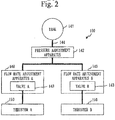
FIG. 2 is a configuration diagram with respect to flowrate adjustment apparatuses 140 in the first embodiment. -
FIG. 3 is a configuration diagram of asatellite controller 120 in the first embodiment. -
FIG. 4 includes graphs each illustrating currentcharacteristic data 123 in the first embodiment. -
FIG. 5 includes diagrams each illustrating unbalanced thrust in the first embodiment. -
FIG. 6 is a graph illustrating an angular momentum when a thrust balance adjustment method in the first embodiment is not performed. -
FIG. 7 is a diagram illustrating thrust balance adjustment in the first embodiment. -
FIG. 8 is a graph illustrating an angular momentum when the thrust balance adjustment method in the first embodiment is performed. -
FIG. 9 is a flowchart of the thrust balance adjustment method in the first embodiment. -
FIG. 10 is a flowchart of an adjustment control process (S120) in the first embodiment. -
FIG. 11 is a configuration diagram of asatellite controller 120 in a second embodiment. -
FIG. 12 includes graphs each illustratingvoltage characteristic data 126 in the second embodiment. -
FIG. 13 is a flowchart of a thrust balance adjustment method in the second embodiment. -
FIG. 14 is a flowchart of an adjustment control process (S220) in the second embodiment. -
FIG. 15 is a configuration diagram of asatellite controller 120 in a third embodiment. -
FIG. 16 is a flowchart of a thrust balance adjustment method in the third embodiment. -
FIG. 17 is a flowchart of the thrust adjustment method in the third embodiment. - A same reference numeral is given to components that are the same or corresponding to each other in embodiments and drawings. Description of the components to which the same reference numeral is given will be suitably omitted or simplified.
- Based on
FIGS. 1 to 10 , a description will be given about an embodiment where balance among thrusts of a plurality of thrusters included in an artificial satellite is adjusted. - A configuration of an
artificial satellite 100 will be described based onFIG. 1 . - The
artificial satellite 100 includes areaction wheel 110, asatellite controller 120, a plurality of power supply apparatuses, a plurality of flow rate adjustment apparatuses, a plurality of thrusters, and areceiver 190. - The
artificial satellite 100 includes a power supply apparatus A and a power supply apparatus B, as the plurality of power supply apparatuses. The power supply apparatus A and the power supply apparatus B are collectively referred to aspower supply apparatuses 130. - The
artificial satellite 100 includes a flow rate adjustment apparatus A and a flow rate adjustment apparatus B, as the plurality of flow rate adjustment apparatuses. The flow rate adjustment apparatus A and the flow rate adjustment apparatus B are collectively referred to as flowrate adjustment apparatuses 140. - The
artificial satellite 100 includes a thruster A and a thruster B, as the plurality of thrusters. The thruster A and the thruster B are collectively referred to asthrusters 150. - Each of a set of the power supply apparatus A, the flow rate adjustment apparatus A, and the thruster A and a set of the power supply apparatus B, the flow rate adjustment apparatus B, and the thruster B constitutes an electric thruster.
- The
reaction wheel 110 is also referred to an RWA (Reaction Wheel Assembly). - The
reaction wheel 110 detects an angular momentum that is generated in theartificial satellite 100 and absorbs the detected angular momentum. - In the first embodiment, the
reaction wheel 110 is used as an angular momentum detection apparatus to detect the angular momentum that is generated in theartificial satellite 100. - An abbreviation for the
satellite controller 120 is an SCU (Satellite Control Unit). - The
satellite controller 120 performs adjustment control for adjusting the balance among the thrusts of the plurality ofthrusters 150. - Each
power supply apparatus 130 is also referred to as a PPU (Power Processing Unit). - The
power supply apparatuses 130 supply adjustment electric powers to adjust flow rates of a propellant that flows through the respective plurality ofthrusters 150 and detect discharge currents that flow through the respective plurality ofthrusters 150. Thepower supply apparatuses 130 supply discharge voltages to the respective plurality ofthrusters 150. - Each flow
rate adjustment apparatus 140 is also referred to as an XFC (Xenon Flow Controller). The flowrate adjustment apparatus 140 referred to as the XFC adjusts a flow rate of xenon gas that is the propellant. - The flow
rate adjustment apparatuses 140 adjust the flow rates of the propellant that flows through the respective plurality ofthrusters 150 by the adjustment electric powers that are supplied from thepower supply apparatuses 130. - Each
thruster 150 is a thruster to obtain a thrust by using electric energy and is also referred to as an EPT (Electric Propulsion Thruster). - The thrust of each
thruster 150 changes according to a discharge current that flows through thethruster 150 and a discharge voltage that is supplied to thethruster 150. - A thrust F of each
thruster 150 can be expressed by the following Expression (1), using a discharge current Id and a discharge voltage Vd where mi is an ion mass and e is an elementary electrical charge. -

- As seen from the above Formula (1), the thrust of each
thruster 150 is proportional to the discharge current Id and is proportional to the square root of the discharge voltage Vd. - A configuration with respect to the flow
rate adjustment apparatuses 140 will be described based onFIG. 2 . - The
artificial satellite 100 further includes atank 141 and a pressure adjustment apparatus 142. The flow rate adjustment apparatus A includes a valve A, and the flow rate adjustment apparatus B includes a valve B. The valve A and the valve B are collectively referred to asvalves 143. - The
tank 141, the pressure adjustment apparatus 142, the flowrate adjustment apparatuses 140, and thethrusters 150 are connected to aflow path 144. - The
tank 141 stores the propellant at a high pressure. - The pressure adjustment apparatus 142 reduces the pressure of the propellant that flows through the
flow path 144 from thetank 141. - Each flow
rate adjustment apparatus 140 adjusts an opening degree of avalve 143, thereby adjusting the flow rate of the propellant that pass through thethruster 150. - A configuration of the
satellite controller 120 will be described based onFIG. 3 . - The
satellite controller 120 includes aprocessor 121 and amemory 122. - The
processor 121 executes processes of thesatellite controller 120. - The
memory 122 stores data that are used, generated, and input/output by thesatellite controller 120. - Specifically, the
memory 122 stores currentcharacteristic data 123,current value data 124, acurrent change amount 125, and so on. - The
current value data 124 is data indicating a discharge current value for eachthruster 150. - The
current change amount 125 is an amount by which the discharge current of eachthruster 150 is to be changed. - The
current change amount 125 is updated according to an instruction from an earth station. - Specifically, the
current change amount 125 is updated as follows. - First, the earth station transmits a command signal including an update instruction to instruct the update of the
current change amount 125 to theartificial satellite 100. The update instruction includes a new current change amount. - Subsequently, the
receiver 190 receives the command signal including the update instruction. - Then, the
satellite controller 120 updates thecurrent change amount 125 stored in thememory 122 to the new current change amount included in the update instruction. - The current
characteristic data 123 will be described based onFIG. 4 . - The current
characteristic data 123 is data indicating a current characteristic for eachthruster 150. The current characteristic is a range of a discharge current that can be flown through eachthruster 150. - A solid line (A) indicates the current characteristic of the thruster A. A current range A is a range of the discharge current that can be flown through the thruster A. A thrust range A is a range of a thrust that the thruster A can obtain.
- A solid line (B) indicates the current characteristic of the thruster B. A current range B is a range of the discharge current that can be flown through the thruster B. A thrust range B is a range of a thrust that the thruster B can obtain.
- The current characteristic of each
thruster 150 is obtained by a test on the earth before theartificial satellite 100 is launched. - The
artificial satellite 100 adjusts balance among thrusts of the plurality ofthrusters 150 in order to restrain accumulation of an angular momentum that is generated in theartificial satellite 100. - Hereinafter, the reason for adjusting the balance among the thrusts of the plurality of
thrusters 150 will be described. - Referring to
FIG. 5 , a distance from the center of gravity of theartificial satellite 100 to the thruster A is referred to as a distance A, while a distance from the center of gravity of theartificial satellite 100 to the thruster B is referred to as a distance B. The thrust of the thruster A is referred to as a thrust A, while the thrust of the thruster B is referred to as a thrust B. - Though the distance A and the distance B are the same to each other, the thrust A and the thrust B are different to each other, in (1) of
FIG. 5 . Such a thrust variation occurs due to an individual difference between thethrusters 150. In this case, a thrust that is given to theartificial satellite 100 by the thruster A and a thrust that is given to theartificial satellite 100 by the thruster B are different to each other. Thus, an angular momentum is generated around the center of gravity of theartificial satellite 100. - Though the thrust A and the thrust B are the same to each other, the distance A and the distance B are different to each other, in (2) of
FIG. 5 . Such a distance variation occurs by a mounting error between thethrusters 150. In this case, a thrust that is given to theartificial satellite 100 by the thruster A and a thrust that is given to theartificial satellite 100 by the thruster B are different to each other. Thus, an angular momentum is generated around the center of gravity of theartificial satellite 100. - Based on
FIG. 6 , a description will be given about a case where balance among thrusts of the plurality ofthrusters 150 is not adjusted. - Since an angular momentum that is generated in the
artificial satellite 100 during a period from T0 to T1 is absorbed by thereaction wheel 110, the attitude of theartificial satellite 100 is maintained. Then, orbit raising is performed. On the other hand, the angular momentum is accumulated in thereaction wheel 110. - During a period from the T1 to T2, unloading is performed in order to release the angular momentum accumulated in the
reaction wheel 110. While the unloading is performed, the orbit raising cannot be performed. - Since the unloading has been finished at the T2, the orbit raising is resumed.
- If the balance among the thrusts of the plurality of
thrusters 150 is not adjusted as mentioned above, the unloading is needed, thus producing a period during which the orbit raising cannot be performed. As a result, a time needed for putting theartificial satellite 100 into a target orbit will increase. - Based on
FIGS. 7 and8 , a description will be given about a case where balance among thrusts of the plurality ofthrusters 150 is adjusted. - (A) of
FIG. 7 illustrates a state where a thrust that is given to theartificial satellite 100 by the thruster A is larger than a thrust that is given to theartificial satellite 100 by the thruster B. - (B) of
FIG. 7 illustrates a state where a thrust that is given to theartificial satellite 100 by the thruster B is larger than a thrust that is given to theartificial satellite 100 by the thruster A. - When the balance among the thrusts of the plurality of
thrusters 150 is adjusted so that the state in (A) ofFIG. 7 and the state in (B) ofFIG. 7 are alternated, a large angular momentum is hardly accumulated in thereaction wheel 110, as illustrated inFIG. 8 . Therefore, the frequency of unloading is reduced, so that a period during which orbit raising cannot be performed is reduced. As a result, it becomes possible to shorten a time needed for putting theartificial satellite 100 into a target orbit. - Then, the
artificial satellite 100 adjusts the balance among the thrusts of the plurality ofthrusters 150 in order to restrain the accumulation of the angular momentum that is generated in theartificial satellite 100. - This method of the adjustment is referred to as a thrust balance adjustment method.
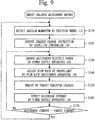
- The thrust balance adjustment method will be described based on
FIG. 9 . - Step S110 is an angular momentum detection process.
- In step S110, the
reaction wheel 110 detects an angular momentum that is generated in theartificial satellite 100. - Then, the
reaction wheel 110 outputs an angular momentum telemetry. The angular momentum telemetry is a signal indicating the detected angular momentum. - The angular momentum telemetry output from the
reaction wheel 110 is input to thesatellite controller 120. - Step S120 is an adjustment control process.
- In step S120, the
satellite controller 120 selects a target thruster from the plurality ofthrusters 150, based on the angular momentum detected in S110. The target thruster is thethruster 150 whose thrust is to be adjusted. - Then, the
satellite controller 120 outputs a current change instruction to thepower supply apparatus 130 associated with the target thruster. The output current change instruction is input to thepower supply apparatus 130 associated with the target thruster. - The current change instruction is a signal that instructs a change in a discharge current that flows through the target thruster. The current change instruction includes a target current value. The target current value is a value that is different from the discharge current of the target thruster before the current change instruction is output, just by the
current change amount 125. - Details of the adjustment control process (S120) will be described later.
- Step S130 is an adjustment electric power change process.
- In step S130, the
power supply apparatus 130 changes adjustment electric power that is supplied to the flowrate adjustment apparatus 140 associated with the target thruster. The adjustment electric power is electric power to adjust a flow rate of the propellant that flows through the target thruster. - Specifically, the
power supply apparatus 130 changes the adjustment electric power, as follows. - The
power supply apparatus 130 detects the discharge current that flows through the target thruster and compares the detected discharge current with a target current. - If the detected discharge current is smaller than the target current, the
power supply apparatus 130 increases the adjustment electric power just by an electric power change amount. The electric power change amount is a value set in advance. - If the detected discharge current is larger than the target current, the
power supply apparatus 130 reduces the adjustment electric power just by the electric power change amount. - Step S140 is a flow rate change process.
- In step S140, the flow
rate adjustment apparatus 140 flows the propellant through the target thruster at a flow rate corresponding to the adjustment electric power after the change. - Specifically, the flow
rate adjustment apparatus 140 adjusts the opening degree of thevalve 143 according to the adjustment electric power after the change. - If the adjustment electric power after the change is larger than the adjustment electric power before the change, the opening degree of the
valve 143 increases, so that the flow rate of the propellant that flows through the target thruster increases. - If the adjustment electric power after the change is smaller than the adjustment electric power before the change, the opening degree of the
valve 143 decreases, so that the flow rate of the propellant that flows through the target thruster decreases. - In step S150, the thrust of the target thruster changes.
- Specifically, if the flow rate of the propellant that flows through the target thruster increases, the thrust of the target thruster increases. If the flow rate of the propellant that flows through the target thruster decreases, the thrust of the target thruster decreases.
- Step S160 is a current detection process.
- In step S160, the
power supply apparatus 130 detects a discharge current that flows through the target thruster. - Step S170 is a current determination process.
- In step S170, the
power supply apparatus 130 compares the detected discharge current with the target current. - Then, the
power supply apparatus 130 determines whether the detected discharge current has become the target current, based on a result of the comparison. - Specifically, if a difference between the detected discharge current and the target current is included in an allowable range, the
power supply apparatus 130 determines that the detected discharge current has become the target current. The allowable range is a current value range set in advance. - If the detected discharge current has become the target current, the procedure proceeds to step S110.
- If the detected discharge current has not become the target current, the procedure proceeds to step S130.
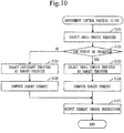
- A procedure for the adjustment control process (S120) will be described based on
FIG. 10 . - In step S121, based on the angular momentum detected in step S110, the
satellite controller 120 selects, among the plurality ofthrusters 150, thethruster 150 whose thrust that is given to theartificial satellite 100 is smaller than a thrust of anyother thruster 150. Thethruster 150 that is selected is referred to a smaller-thrust thruster. - In step S122, based on the discharge current that flows through the small-thrust thruster, the
satellite controller 120 determines whether the thrust of the small-thrust thruster can be increased. - Specifically, the
satellite controller 120 makes the determination as follows. - First, the
satellite controller 120 obtains, from thecurrent value data 124, the value of the discharge current of the small-thrust thruster. - Then, the
satellite controller 120 adds thecurrent change amount 125 to the value of the discharge current of the small-thrust thruster. A value that is obtained by the addition is referred to a temporary current value. - Subsequently, the
satellite controller 120 selects, from the currentcharacteristic data 123, the current characteristic of the small-thrust thruster. - Then, the
satellite controller 120 determines whether the temporary current value is included in a current range indicated by the current characteristic of the small-thrust thruster. - If the temporary current value is included in the current range indicated by the current characteristic of the small-thrust thruster, the thrust of the small-thrust thruster can be increased.
- If the temporary current value is not included in the current range indicated by the current characteristic of the small-thrust thruster, the thrust of the small-thrust thruster cannot be increased.
- If the thrust of the small-thrust thruster can be increased, the procedure proceeds to step S123.
- If the thrust of the small-thrust thruster cannot be increased, the procedure proceeds to step S125.
- In step S123, the
satellite controller 120 selects the small-thrust thruster as the target thruster. - In step S124, the
satellite controller 120 computes the target current value, using the discharge current value of the target thruster and thecurrent change amount 125. - Then, the
satellite controller 120 selects the discharge current value of the target thruster from thecurrent value data 124 and updates the selected value to the target current value. - Specifically, the
satellite controller 120 computes the target current value as follows. - The
satellite controller 120 obtains, from thecurrent value data 124, the discharge current value of the target thruster. - Then, the
satellite controller 120 adds thecurrent change amount 125 to the discharge current value of the target thruster. The value that is obtained by the addition is the target current value. - In step S125, the
satellite controller 120 selects adifferent thruster 150 as the target thruster. - Specifically, if the small-thrust thruster is the thruster A, the thruster B is selected as the target thruster.
- In step S126, the
satellite controller 120 computes the target current value, using the discharge current value of the target thruster and thecurrent change amount 125. - Then, the
satellite controller 120 selects, from thecurrent value data 124, the discharge current value of the target thruster and updates the selected value to the target current value. - Specifically, the
satellite controller 120 computes the target current value as follows. - The
satellite controller 120 obtains, from thecurrent value data 124, the discharge current value of the target thruster. - Then, the
satellite controller 120 subtracts thecurrent change amount 125 from the discharge current value of the target thruster. A value that is obtained by the subtraction is the target current value. - In step S127, the
satellite controller 120 outputs the current change instruction including the target current value. - Specifically, the
satellite controller 120 outputs the current change instruction as follows. - First, the
satellite controller 120 generates the current change instruction including the target current value computed in step S124 or step S126. - Subsequently, the
satellite controller 120 selects thepower supply apparatus 130 associated with the target thruster selected in step S123 or step S125. If the target thruster is the thruster A, thepower supply apparatus 130 associated with the target thruster is the power supply apparatus A. If the target thruster is the thruster B, thepower supply apparatus 130 associated with the target thruster is the power supply apparatus B. - Then, the
satellite controller 120 outputs the generated current change instruction to the selectedpower supply apparatus 130. The output current change instruction is input to the selectedpower supply apparatus 130. - By controlling the discharge current of the target thruster, the adjustment of balance among the thrusts of the plurality of
thrusters 150 becomes possible. - This prevents a large angular momentum from being accumulated in the
reaction wheel 110, reduces the frequency of unloading, and reduces a period during which orbit raising cannot be performed. - As a result, it becomes possible to shorten a time needed for putting the
artificial satellite 100 to be put into a target orbit. - The
artificial satellite 100 may include both of an electric thruster and a chemical thruster. - The number of the
thrusters 150 may be three or more. - A propellant other than the xenon gas may be used.
- With respect to an embodiment where balance among thrusts of a plurality of
thrusters 150 is adjusted by controlling a discharge voltage of a target thruster, a difference of the embodiment from the first embodiment will be mainly described based onFIGS. 11 to 14 . - A configuration of an
artificial satellite 100 is the same as that inFIGS. 1 and2 in the first embodiment. - However, a change instruction that is output from a
satellite controller 120 is not a current change instruction in the first embodiment but is a voltage change instruction. The voltage change instruction will be described later. - A configuration of the
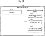
satellite controller 120 will be described based onFIG. 11 . - The
satellite controller 120 includes aprocessor 121 and amemory 122, as inFIG. 3 in the first embodiment. - The
memory 122 stores voltagecharacteristic data 126,voltage value data 127, and avoltage change amount 128. - The
voltage value data 127 is data indicating a discharge voltage value for eachthruster 150. - The
voltage change amount 128 is an amount by which the discharge voltage of eachthruster 150 is to be changed. - The
voltage change amount 128 is updated according to an instruction from an earth station. - Specifically, the
voltage change amount 128 is updated as follows. - First, the earth station transmits, to the
artificial satellite 100, a command signal including an update instruction to instruct the update of thevoltage change amount 128. The update instruction includes a new voltage change amount. - Subsequently, a
receiver 190 receives the command signal including the update instruction. - Then, the
satellite controller 120 updates thevoltage change amount 128 stored in thememory 122 to the new voltage change amount included in the update instruction. - The voltage
characteristic data 126 will be described based onFIG. 12 . - The voltage
characteristic data 126 is data indicating a voltage characteristic for eachthruster 150. The voltage characteristic is a range of a discharge voltage that can be applied to eachthruster 150. - A solid line (A) indicates the voltage characteristic of a thruster A. A voltage range A is a range of the discharge voltage that can be applied to the thruster A. A thrust range A is a range of a thrust that the thruster A can obtain.
- A solid line (B) indicates the voltage characteristic of a thruster B. A voltage range B is a range of the discharge voltage that can be applied to the thruster B. A thrust range B is a range of a thrust that the thruster B can obtain.
- The voltage characteristic of each
thruster 150 is obtained by a test on the earth before theartificial satellite 100 is launched. - A thrust balance adjustment method will be described based on
FIG. 13 . - Step S210 is the same as step S110 in
FIG. 9 in the first embodiment. - In step S210, a
reaction wheel 110 detects an angular momentum that is generated in theartificial satellite 100. - Step S220 is an adjustment control process.
- In step S220, the
satellite controller 120 selects, from the plurality ofthrusters 150, a target thruster, based on the angular momentum detected in step S210. - Then, the
satellite controller 120 outputs a voltage change instruction to apower supply apparatus 130 associated with the target thruster. The output voltage change instruction is input to thepower supply apparatus 130 associated with the target thruster. - The voltage change instruction is a signal that instructs a change in a discharge voltage that is supplied to the target thruster. The voltage change instruction includes a target voltage value. The target voltage value is a value different from the discharge voltage of the target thruster before the voltage change instruction is output, just by the
voltage change amount 128. - Details of the adjustment control process (S220) will be described later.
- Step S230 is a discharge voltage change process.
- In step S230, the
power supply apparatus 130 changes the discharge voltage that is supplied to the target thruster to a target voltage. In other words, thepower supply apparatus 130 supplies the target voltage to the target thruster. - In step S240, the thrust of the target thruster changes.
- Specifically, the thrust of the target thruster increases as the discharge voltage that is supplied to the target thruster becomes high. The thrust of the target thruster decreases as the discharge voltage that is supplied to the target thruster becomes low.
- After step S240, the procedure proceeds to step S210.
- A procedure for the adjustment control process (S220) will be described based on
FIG. 14 . - In step S221, based on the angular momentum detected in step S210, the
satellite controller 120 selects, among the plurality ofthrusters 150, thethruster 150 whose thrust that is given to theartificial satellite 100 is smaller than a thrust of anyother thruster 150. Thethruster 150 that is selected is referred to as a small-thrust thruster. - In step S222, based on the discharge voltage that flows through the small-thrust thruster, the
satellite controller 120 determines whether the thrust of the small-thrust thruster can be increased. - Specifically, the
satellite controller 120 makes the determination as follows. - First, the
satellite controller 120 obtains, from thevoltage value data 127, the value of the discharge voltage of the small-thrust thruster. - Then, the
satellite controller 120 adds thevoltage change amount 128 to the value of the discharge voltage of the small-thrust thruster. A value that is obtained by the addition is referred to a temporary voltage value. - Subsequently, the
satellite controller 120 selects, from the voltagecharacteristic data 126, the voltage characteristic of the small-thrust thruster. - Then, the
satellite controller 120 determines whether the temporary voltage value is included in a voltage range indicated by the voltage characteristic of the small-thrust thruster. - If the temporary voltage value is included in the voltage range indicated by the voltage characteristic of the small-thrust thruster, the thrust of the small-thrust thruster can be increased.
- If the temporary voltage value is not included in the voltage range indicated by the voltage characteristic of the small-thrust thruster, the thrust of the small-thrust thruster cannot be increased.
- If the thrust of the small-thrust thruster can be increased, the procedure proceeds to step S223.
- If the thrust of the small-thrust thruster cannot be increased, the procedure proceeds to step S225.
- In step S223, the
satellite controller 120 selects the small-thrust thruster as the target thruster. - In step S224, the
satellite controller 120 computes the target voltage value, using the discharge voltage value of the target thruster and thevoltage change amount 128. - Then, the
satellite controller 120 selects the discharge voltage value of the target thruster from thevoltage value data 127 and updates the selected value to the target voltage value. - Specifically, the
satellite controller 120 computes the target voltage value as follows. - The
satellite controller 120 obtains, from thevoltage value data 127, the discharge voltage value of the target thruster. - Then, the
satellite controller 120 adds thevoltage change amount 128 to the discharge voltage value of the target thruster. A value that is obtained by the addition is the target voltage value. - In step S225, the
satellite controller 120 selects adifferent thruster 150 as the target thruster. - Specifically, if the small-thrust thruster is the thruster A, the thruster B is selected as the target thruster.
- In step S226, the
satellite controller 120 computes the target voltage value, using the discharge voltage value of the target thruster and thevoltage change amount 128. - Then, the
satellite controller 120 selects, from thevoltage value data 127, the discharge voltage value of the target thruster and updates the selected value to the target voltage value. - Specifically, the
satellite controller 120 computes the target voltage value as follows. - The
satellite controller 120 obtains, from thevoltage value data 127, the discharge voltage value of the target thruster. - Then, the
satellite controller 120 subtracts thevoltage change amount 128 from the discharge voltage value of the target thruster. A value that is obtained by the subtraction is the target voltage value. - In step S227, the
satellite controller 120 outputs the voltage change instruction including the target voltage value. - Specifically, the
satellite controller 120 outputs the voltage change instruction as follows. - First, the
satellite controller 120 generates the voltage change instruction including the target voltage value computed in step S224 or step S226. - Subsequently, the
satellite controller 120 selects thepower supply apparatus 130 associated with the target thruster selected in step S223 or step S225. If the target thruster is the thruster A, thepower supply apparatus 130 associated with the target thruster is a power supply apparatus A. If the target thruster is the thruster B, thepower supply apparatus 130 associated with the target thruster is a power supply apparatus B. - Then, the
satellite controller 120 outputs the generated voltage change instruction to the selectedpower supply apparatus 130. The output current change instruction is input to the selectedpower supply apparatus 130. - By controlling the discharge voltage of the target thruster, the adjustment of the balance among the thrusts of the plurality of
thrusters 150 becomes possible. - As a result, it becomes possible to shorten a time needed for putting the
artificial satellite 100 to be put into a target orbit, as in the first embodiment. - With respect to an embodiment where balance among thrusts of a plurality of
thrusters 150 is adjusted by controlling a discharge current of a target thruster or a discharge voltage of the target thruster, a difference of the embodiment from the first embodiment and the second embodiment will be described based onFIGS. 15 to 17 . - A configuration of an
artificial satellite 100 is the same as that inFIGS. 1 and2 in the first embodiment. - A change instruction that is output from a
satellite controller 120 is a current change instruction in the first embodiment or a voltage change instruction in the second embodiment. - A configuration of the
satellite controller 120 will be described based onFIG. 15 . - The
satellite controller 120 includes aprocessor 121 and amemory 122, as inFIG. 3 in the first embodiment. - The
memory 122 stores currentcharacteristic data 123,current value data 124, acurrent change amount 125, voltagecharacteristic data 126,voltage value data 127, avoltage change amount 128, and achange type 129. - The
change type 129 indicates one of a current change and a voltage change. Thechange type 129 is updated according to an instruction from an earth station. Specifically, thechange type 129 is updated as follows. - First, the earth station transmits, to the
artificial satellite 100, a command signal including a type instruction to instruct one of change types of the current change and the voltage change. - Subsequently, a
receiver 190 receives the command signal including the type instruction. - Then, the
satellite controller 120 updates thechange type 129 stored in thememory 122 to the change type instructed by the type instruction. - A thrust balance adjustment method will be described based on
FIGS. 16 and17 . - Step S110 in
FIG. 16 is the same as that inFIG. 9 in the first embodiment. - Step S300 is a type determination process.
- In step S300, the
satellite controller 120 determines which one of the current change and the voltage change thechange type 129 is. - If the
change type 129 is the current change, the procedure proceeds to step S120. Processes after step S120 are the same as those inFIG. 9 in the first embodiment. - If the
change type 129 is the voltage change, the procedure proceeds to step S220 inFIG. 17 . Processes after step S220 are same as those inFIG. 13 in the second embodiment. - By controlling the discharge current of the target thruster or the discharge voltage of the target thruster, the adjustment of the balance among the thrusts of the plurality of
thrusters 150 becomes possible. - As a result, it becomes possible to shorten a time needed for the
artificial satellite 100 to be put into a target orbit, as in the first embodiment. - The embodiments are each an illustration of a preferred embodiment and does not intend to limit the technical range of the present invention. Each embodiment may be partially carried out or may be carried out in combination with a different embodiment. Each procedure described using the flowchart or the like may be suitably modified.
-
- 100
- artificial satellite
- 110
- reaction wheel
- 120
- satellite controller
- 121
- processor
- 122
- memory
- 123
- current characteristic data
- 124
- current value data
- 125
- current change amount
- 126
- voltage characteristic data
- 127
- voltage value data
- 128
- voltage change amount
- 129
- change type
- 130
- power supply apparatus
- 140
- flow rate adjustment apparatus
- 141
- tank
- 142
- pressure adjustment apparatus
- 143
- valve
- 144
- flow path
- 150
- thruster
- 190
- receiver
Claims (10)
- An artificial satellite
comprising:- a plurality of thrusters;- an angular momentum detection apparatus to detect an angular momentum that is generated in the artificial satellite; and- a satellite controller to perform adjustment control of selecting, from the plurality of thrusters, a target thruster whose thrust is to be adjusted, based on the detected angular momentum, and adjusting the thrust of the target thruster. - The artificial satellite according to claim 1,
wherein the satellite controller selects one of the plurality of thrusters whose thrust that is given to the artificial satellite is smaller than a thrust of any other thruster,
determines whether the thrust of the selected thruster can be increased, based on a discharge current that flows through the selected thruster,
selects the selected thruster as the target thruster when the thrust of the selected thruster can be increased, and
selects a different one of the plurality of thrusters as the target thruster when the thrust of the selected thruster cannot be increased. - The artificial satellite according to claim 1 or 2,
comprising:a power supply apparatus to supply adjustment electric power to adjust a flow rate of a propellant that flows through each of the plurality of thrusters and detect a discharge current that flows through each of the plurality of thrusters; anda flow rate adjustment apparatus to adjust the flow rate of the propellant that flows through each of the plurality of thrusters by the adjustment electric power that is supplied,wherein the satellite controller outputs a current change instruction to instruct a change in the discharge current that flows through the target thruster, as the adjustment control,wherein the power supply apparatus changes the adjustment electric power to adjust the flow rate of the propellant that flows through the target thruster when the current change instruction is output,wherein the flow rate adjustment apparatus flows the propellant through the target thruster at a flow rate corresponding to the adjustment electric power after the change, andwherein the power supply apparatus detects a discharge current that flows through the target thruster after the current change instruction has been output, and further changes the adjustment electric power for the target thruster when the detected discharge current does not become a target current. - The artificial satellite according to claim 3,
wherein the current change instruction includes a value of the target current,
wherein the value of the target current is a value different from the discharge current of the target thruster before the current change instruction is output, just by a current change amount,
wherein the artificial satellite comprises a receiver to receive an update instruction to instruct an update of the current change amount, and
wherein the satellite controller updates the current change amount when the update instruction is received. - The artificial satellite according to claim 1,
wherein the satellite controller selects one of the plurality of thrusters whose thrust that is given to the artificial satellite is smaller than a thrust of any other thruster,
determines whether the thrust of the selected thruster can be increased, based on a discharge voltage that is supplied to the selected thruster,
selects the selected thruster as the target thruster when the thrust of the selected thruster can be increased, and
selects a different one of the other thrusters as the target thruster when the thrust of the selected thruster cannot be increased. - The artificial satellite according to claim 1 or 5,
comprising:a power supply apparatus to supply a discharge voltage to each of the plurality of thrusters,wherein the satellite controller outputs a voltage change instruction to instruct a change in the discharge voltage that is supplied to the target thruster, as the adjustment control, andwherein the power supply apparatus changes the discharge voltage that is supplied to the target thruster to a target voltage when the voltage change instruction is output. - The artificial satellite according to claim 6,
wherein the voltage change instruction includes a value of the target voltage,
wherein the value of the target voltage is a value different from the discharge voltage of the target thruster before the voltage change instruction is output, just by a voltage change amount,
wherein the artificial satellite comprises a receiver to receive an update instruction to instruct an update of the voltage change amount, and
wherein the satellite controller updates the voltage change amount when the update instruction is received. - The artificial satellite according to any one of claims 1, 2, and 5,
comprising:a receiver to receive a type instruction to instruct one of a current change and a voltage change;a power supply apparatus to supply a discharge voltage to each of the plurality of thrusters, supply adjustment electric power to adjust a flow rate of a propellant that flows through each of the plurality of thrusters, and detect a discharge current that flows through each of the plurality of thrusters; anda flow rate adjustment apparatus to adjust the flow rate of the propellant that flows through each of the plurality of thrusters by the adjustment electric power that is supplied,wherein, as the adjustment control, the satellite controller outputs a current change instruction to instruct a change in the discharge current that flows through the target thruster when the type instruction instructs the current change, and outputs a voltage change instruction to instruct a change in the discharge voltage that is supplied to the target thruster when the type instruction instructs the voltage change,wherein when the current change instruction is output, the power supply apparatus changes the adjustment electric power to adjust the flow rate of the propellant that flows through the target thruster, the flow rate adjustment apparatus flows the propellant through the target thruster at a flow rate corresponding to the adjustment electric power after the change, the power supply apparatus detects a discharge current that flows through the target thruster after the current change instruction has been output, and further changes the adjustment electric power for the target thruster when the detected discharge current does not become a target current, andwherein when the voltage change instruction is output, the power supply apparatus changes the discharge voltage that is supplied to the target thruster to a target voltage. - The artificial satellite according to claim 8,
wherein the current change instruction includes a value of the target current,
wherein the value of the target current is a value different from the discharge current of the target thruster before the current change instruction is output, just by a current change amount,
wherein the voltage change instruction includes a value of the target voltage, wherein the value of the target voltage is a value different from the discharge voltage of the target thruster before the voltage change instruction is output, just by a voltage change amount,
wherein the artificial satellite comprises a receiver to receive a first update instruction to instruct a change in the current change amount and a second update instruction to instruct a change in the voltage change amount, and
wherein the satellite controller updates the current change amount when the first update instruction is received and updates the voltage change amount when the second update instruction is received. - A thrust balance adjustment method of adjusting balance among thrusts of a plurality of thrusters included in an artificial satellite,
comprising:detecting an angular momentum that is generated in the artificial satellite, by an angular momentum detection apparatus; andperforming adjustment control of selecting, from the plurality of thrusters, a target thruster whose thrust is to be adjusted, based on the detected angular momentum and adjusting the thrust of the target thruster, by a satellite controller.
Applications Claiming Priority (1)
| Application Number | Priority Date | Filing Date | Title |
|---|---|---|---|
| PCT/JP2016/069106 WO2018003005A1 (en) | 2016-06-28 | 2016-06-28 | Artificial satellite and method for adjusting thrust balance |
Publications (3)
| Publication Number | Publication Date |
|---|---|
| EP3476749A1 true EP3476749A1 (en) | 2019-05-01 |
| EP3476749A4 EP3476749A4 (en) | 2019-06-12 |
| EP3476749B1 EP3476749B1 (en) | 2021-11-17 |
Family
ID=60786155
Family Applications (1)
| Application Number | Title | Priority Date | Filing Date |
|---|---|---|---|
| EP16907238.6A Active EP3476749B1 (en) | 2016-06-28 | 2016-06-28 | Artificial satellite and thrust balance adjustment method |
Country Status (4)
| Country | Link |
|---|---|
| US (1) | US11117685B2 (en) |
| EP (1) | EP3476749B1 (en) |
| JP (1) | JP6541880B2 (en) |
| WO (1) | WO2018003005A1 (en) |
Families Citing this family (5)
| Publication number | Priority date | Publication date | Assignee | Title |
|---|---|---|---|---|
| JP6556371B2 (en) * | 2016-09-09 | 2019-08-07 | 三菱電機株式会社 | Attitude control device, attitude control system, ground station, artificial satellite, attitude control method and program |
| US11346306B1 (en) | 2019-01-03 | 2022-05-31 | Ball Aerospace & Technologies Corp. | Chemical and cold gas propellant systems and methods |
| US11498705B1 (en) | 2019-05-09 | 2022-11-15 | Ball Aerospace & Technology Corp. | On orbit fluid propellant dispensing systems and methods |
| US12012233B2 (en) | 2021-05-10 | 2024-06-18 | Ball Aerospace & Technologies Corp. | Active on orbit fluid propellant management and refueling systems and methods |
| US11945606B1 (en) | 2021-10-19 | 2024-04-02 | Ball Aerospace & Technologies Corp. | Electric propulsion based spacecraft propulsion systems and methods utilizing multiple propellants |
Family Cites Families (19)
| Publication number | Priority date | Publication date | Assignee | Title |
|---|---|---|---|---|
| JPS5950897A (en) * | 1982-09-14 | 1984-03-24 | 三菱電機株式会社 | Thruster attitude control system of space missile |
| JPS60252100A (en) * | 1984-05-29 | 1985-12-12 | 三菱電機株式会社 | Controller for attitude of artificial satellite |
| JPS62244798A (en) * | 1986-04-18 | 1987-10-26 | 日本電気株式会社 | Orbit correction and unloading method of geostationary satellite |
| JPH0825519B2 (en) * | 1988-10-25 | 1996-03-13 | 日本電気株式会社 | Orbit controller for artificial satellites |
| JPH02124400A (en) | 1988-10-31 | 1990-05-11 | Natl Space Dev Agency Japan<Nasda> | Track change propulsive device |
| JP2942568B2 (en) | 1989-02-13 | 1999-08-30 | 株式会社東芝 | Orbit conversion propulsion device |
| GB9127433D0 (en) * | 1991-12-27 | 1992-02-19 | Matra Marconi Space Uk | Propulsion system for spacecraft |
| US5349532A (en) * | 1992-04-28 | 1994-09-20 | Space Systems/Loral | Spacecraft attitude control and momentum unloading using gimballed and throttled thrusters |
| JPH06249132A (en) * | 1993-02-22 | 1994-09-06 | Mitsubishi Electric Corp | Ion engine device |
| JPH06305496A (en) * | 1993-04-21 | 1994-11-01 | Nec Corp | Orbit control device for artificial satellite |
| US5984236A (en) * | 1995-12-22 | 1999-11-16 | Keitel; Keith F. | Momentum unloading using gimbaled thrusters |
| JP2000128096A (en) | 1998-10-28 | 2000-05-09 | Mitsubishi Electric Corp | Method and apparatus for maintaining geosynchronous orbit of three-axis attitude control satellite |
| US6296207B1 (en) * | 1999-01-27 | 2001-10-02 | Space Systems/Loral, Inc. | Combined stationkeeping and momentum management |
| JP2001287699A (en) * | 2000-04-05 | 2001-10-16 | Mitsubishi Electric Corp | Satellite attitude control device |
| US7118075B2 (en) * | 2003-06-13 | 2006-10-10 | Schubert Peter J | System and method for attitude control and station keeping |
| US8550405B2 (en) * | 2009-09-29 | 2013-10-08 | Busek Company, Inc. | Solar powered spacecraft power system for a hall effect thruster |
| FR2986577B1 (en) * | 2012-02-06 | 2016-05-20 | Snecma | HALL EFFECTOR |
| US10183765B2 (en) * | 2014-03-12 | 2019-01-22 | Lockheed Martin Corporation | Thruster arrangement for geosynchronous orbit spacecraft |
| US9428285B2 (en) * | 2014-08-17 | 2016-08-30 | The Boeing Company | System and method for managing momentum accumulation |
-
2016
- 2016-06-28 EP EP16907238.6A patent/EP3476749B1/en active Active
- 2016-06-28 WO PCT/JP2016/069106 patent/WO2018003005A1/en not_active Ceased
- 2016-06-28 US US16/300,213 patent/US11117685B2/en active Active
- 2016-06-28 JP JP2018524615A patent/JP6541880B2/en active Active
Also Published As
| Publication number | Publication date |
|---|---|
| JP6541880B2 (en) | 2019-07-10 |
| US11117685B2 (en) | 2021-09-14 |
| EP3476749A4 (en) | 2019-06-12 |
| WO2018003005A1 (en) | 2018-01-04 |
| EP3476749B1 (en) | 2021-11-17 |
| JPWO2018003005A1 (en) | 2018-08-16 |
| US20190144140A1 (en) | 2019-05-16 |
Similar Documents
| Publication | Publication Date | Title |
|---|---|---|
| EP3476749B1 (en) | Artificial satellite and thrust balance adjustment method | |
| De Grys et al. | Demonstration of 10,400 hours of operation on 4.5 kw qualification model hall thruster | |
| Polk et al. | Demonstration of the NSTAR ion propulsion system on the Deep Space One mission | |
| Brophy et al. | Ion propulsion system (NSTAR) DS1 technology validation report | |
| Koppel et al. | The SMART-1 Hall effect thruster around the moon: In flight experience | |
| US11401053B2 (en) | Autonomous control of electric power supplied to a thruster during electric orbit raising | |
| US11753188B2 (en) | Optimized power balanced low thrust transfer orbits utilizing split thruster execution | |
| EP3670359B1 (en) | Optimized power balanced variable thrust transfer orbits to minimize an electric orbit raising duration | |
| Randall et al. | BepiColombo–MEPS commissioning activities and T6 ion thruster performance during early mission operations | |
| Ataka et al. | Improving the performance of a water ion thruster using biased electrodes | |
| Clark et al. | BepiColombo—Solar Electric Propulsion System Test and Qualification Approach | |
| Di Cara et al. | Smart-1: An analysis of flight data | |
| Lascombes et al. | Lessons learnt from operating the first cubesat mission equipped with a hall thruster | |
| Bassner et al. | Development steps of the RF-ion thrusters RIT | |
| Leiter et al. | Evaluation of the performance of the advanced 200mn radio-frequency ion thruster rit-xt | |
| Vaughn et al. | Review of the ProSEDS electrodynamic tether mission development | |
| Milligan et al. | SMART-1 electric propulsion operational experience | |
| EP1852350B1 (en) | Method of operating a geostationary satellite and satellite control system for implementing said method | |
| Duchemin et al. | Endurance Test at High Voltage of the PPS X000 Hall-Effect Thruster | |
| Renault et al. | Electric propulsion on ARTEMIS: a development status | |
| Bradley et al. | Navigation models for Psyche electric propulsion uncertainty | |
| Nishiyama et al. | In-flight operation of the Hayabusa2 ion engine system in the EDVEGA phase | |
| Bassner et al. | Advantages and applications of the RF-ion thrusters RIT | |
| Dumazert et al. | PPS-1350-G qualification status | |
| Killinger et al. | Final report on the Artemis salvage mission using electric propulsion |
Legal Events
| Date | Code | Title | Description |
|---|---|---|---|
| STAA | Information on the status of an ep patent application or granted ep patent |
Free format text: STATUS: THE INTERNATIONAL PUBLICATION HAS BEEN MADE |
|
| PUAI | Public reference made under article 153(3) epc to a published international application that has entered the european phase |
Free format text: ORIGINAL CODE: 0009012 |
|
| STAA | Information on the status of an ep patent application or granted ep patent |
Free format text: STATUS: REQUEST FOR EXAMINATION WAS MADE |
|
| 17P | Request for examination filed |
Effective date: 20181214 |
|
| AK | Designated contracting states |
Kind code of ref document: A1 Designated state(s): AL AT BE BG CH CY CZ DE DK EE ES FI FR GB GR HR HU IE IS IT LI LT LU LV MC MK MT NL NO PL PT RO RS SE SI SK SM TR |
|
| AX | Request for extension of the european patent |
Extension state: BA ME |
|
| A4 | Supplementary search report drawn up and despatched |
Effective date: 20190515 |
|
| RIC1 | Information provided on ipc code assigned before grant |
Ipc: B64G 1/28 20060101ALI20190509BHEP Ipc: B64G 1/26 20060101AFI20190509BHEP Ipc: B64G 1/40 20060101ALI20190509BHEP |
|
| DAV | Request for validation of the european patent (deleted) | ||
| DAX | Request for extension of the european patent (deleted) | ||
| STAA | Information on the status of an ep patent application or granted ep patent |
Free format text: STATUS: EXAMINATION IS IN PROGRESS |
|
| 17Q | First examination report despatched |
Effective date: 20200504 |
|
| GRAP | Despatch of communication of intention to grant a patent |
Free format text: ORIGINAL CODE: EPIDOSNIGR1 |
|
| STAA | Information on the status of an ep patent application or granted ep patent |
Free format text: STATUS: GRANT OF PATENT IS INTENDED |
|
| INTG | Intention to grant announced |
Effective date: 20201207 |
|
| GRAJ | Information related to disapproval of communication of intention to grant by the applicant or resumption of examination proceedings by the epo deleted |
Free format text: ORIGINAL CODE: EPIDOSDIGR1 |
|
| STAA | Information on the status of an ep patent application or granted ep patent |
Free format text: STATUS: EXAMINATION IS IN PROGRESS |
|
| INTC | Intention to grant announced (deleted) | ||
| GRAS | Grant fee paid |
Free format text: ORIGINAL CODE: EPIDOSNIGR3 |
|
| STAA | Information on the status of an ep patent application or granted ep patent |
Free format text: STATUS: GRANT OF PATENT IS INTENDED |
|
| GRAP | Despatch of communication of intention to grant a patent |
Free format text: ORIGINAL CODE: EPIDOSNIGR1 |
|
| INTG | Intention to grant announced |
Effective date: 20210531 |
|
| GRAA | (expected) grant |
Free format text: ORIGINAL CODE: 0009210 |
|
| STAA | Information on the status of an ep patent application or granted ep patent |
Free format text: STATUS: THE PATENT HAS BEEN GRANTED |
|
| AK | Designated contracting states |
Kind code of ref document: B1 Designated state(s): AL AT BE BG CH CY CZ DE DK EE ES FI FR GB GR HR HU IE IS IT LI LT LU LV MC MK MT NL NO PL PT RO RS SE SI SK SM TR |
|
| REG | Reference to a national code |
Ref country code: GB Ref legal event code: FG4D |
|
| REG | Reference to a national code |
Ref country code: DE Ref legal event code: R096 Ref document number: 602016066469 Country of ref document: DE |
|
| REG | Reference to a national code |
Ref country code: IE Ref legal event code: FG4D |
|
| REG | Reference to a national code |
Ref country code: AT Ref legal event code: REF Ref document number: 1447868 Country of ref document: AT Kind code of ref document: T Effective date: 20211215 |
|
| REG | Reference to a national code |
Ref country code: LT Ref legal event code: MG9D |
|
| REG | Reference to a national code |
Ref country code: NL Ref legal event code: MP Effective date: 20211117 |
|
| REG | Reference to a national code |
Ref country code: AT Ref legal event code: MK05 Ref document number: 1447868 Country of ref document: AT Kind code of ref document: T Effective date: 20211117 |
|
| PG25 | Lapsed in a contracting state [announced via postgrant information from national office to epo] |
Ref country code: RS Free format text: LAPSE BECAUSE OF FAILURE TO SUBMIT A TRANSLATION OF THE DESCRIPTION OR TO PAY THE FEE WITHIN THE PRESCRIBED TIME-LIMIT Effective date: 20211117 Ref country code: LT Free format text: LAPSE BECAUSE OF FAILURE TO SUBMIT A TRANSLATION OF THE DESCRIPTION OR TO PAY THE FEE WITHIN THE PRESCRIBED TIME-LIMIT Effective date: 20211117 Ref country code: FI Free format text: LAPSE BECAUSE OF FAILURE TO SUBMIT A TRANSLATION OF THE DESCRIPTION OR TO PAY THE FEE WITHIN THE PRESCRIBED TIME-LIMIT Effective date: 20211117 Ref country code: BG Free format text: LAPSE BECAUSE OF FAILURE TO SUBMIT A TRANSLATION OF THE DESCRIPTION OR TO PAY THE FEE WITHIN THE PRESCRIBED TIME-LIMIT Effective date: 20220217 Ref country code: AT Free format text: LAPSE BECAUSE OF FAILURE TO SUBMIT A TRANSLATION OF THE DESCRIPTION OR TO PAY THE FEE WITHIN THE PRESCRIBED TIME-LIMIT Effective date: 20211117 |
|
| PG25 | Lapsed in a contracting state [announced via postgrant information from national office to epo] |
Ref country code: IS Free format text: LAPSE BECAUSE OF FAILURE TO SUBMIT A TRANSLATION OF THE DESCRIPTION OR TO PAY THE FEE WITHIN THE PRESCRIBED TIME-LIMIT Effective date: 20220317 Ref country code: SE Free format text: LAPSE BECAUSE OF FAILURE TO SUBMIT A TRANSLATION OF THE DESCRIPTION OR TO PAY THE FEE WITHIN THE PRESCRIBED TIME-LIMIT Effective date: 20211117 Ref country code: PT Free format text: LAPSE BECAUSE OF FAILURE TO SUBMIT A TRANSLATION OF THE DESCRIPTION OR TO PAY THE FEE WITHIN THE PRESCRIBED TIME-LIMIT Effective date: 20220317 Ref country code: PL Free format text: LAPSE BECAUSE OF FAILURE TO SUBMIT A TRANSLATION OF THE DESCRIPTION OR TO PAY THE FEE WITHIN THE PRESCRIBED TIME-LIMIT Effective date: 20211117 Ref country code: NO Free format text: LAPSE BECAUSE OF FAILURE TO SUBMIT A TRANSLATION OF THE DESCRIPTION OR TO PAY THE FEE WITHIN THE PRESCRIBED TIME-LIMIT Effective date: 20220217 Ref country code: NL Free format text: LAPSE BECAUSE OF FAILURE TO SUBMIT A TRANSLATION OF THE DESCRIPTION OR TO PAY THE FEE WITHIN THE PRESCRIBED TIME-LIMIT Effective date: 20211117 Ref country code: LV Free format text: LAPSE BECAUSE OF FAILURE TO SUBMIT A TRANSLATION OF THE DESCRIPTION OR TO PAY THE FEE WITHIN THE PRESCRIBED TIME-LIMIT Effective date: 20211117 Ref country code: HR Free format text: LAPSE BECAUSE OF FAILURE TO SUBMIT A TRANSLATION OF THE DESCRIPTION OR TO PAY THE FEE WITHIN THE PRESCRIBED TIME-LIMIT Effective date: 20211117 Ref country code: GR Free format text: LAPSE BECAUSE OF FAILURE TO SUBMIT A TRANSLATION OF THE DESCRIPTION OR TO PAY THE FEE WITHIN THE PRESCRIBED TIME-LIMIT Effective date: 20220218 Ref country code: ES Free format text: LAPSE BECAUSE OF FAILURE TO SUBMIT A TRANSLATION OF THE DESCRIPTION OR TO PAY THE FEE WITHIN THE PRESCRIBED TIME-LIMIT Effective date: 20211117 |
|
| PG25 | Lapsed in a contracting state [announced via postgrant information from national office to epo] |
Ref country code: SM Free format text: LAPSE BECAUSE OF FAILURE TO SUBMIT A TRANSLATION OF THE DESCRIPTION OR TO PAY THE FEE WITHIN THE PRESCRIBED TIME-LIMIT Effective date: 20211117 Ref country code: SK Free format text: LAPSE BECAUSE OF FAILURE TO SUBMIT A TRANSLATION OF THE DESCRIPTION OR TO PAY THE FEE WITHIN THE PRESCRIBED TIME-LIMIT Effective date: 20211117 Ref country code: RO Free format text: LAPSE BECAUSE OF FAILURE TO SUBMIT A TRANSLATION OF THE DESCRIPTION OR TO PAY THE FEE WITHIN THE PRESCRIBED TIME-LIMIT Effective date: 20211117 Ref country code: EE Free format text: LAPSE BECAUSE OF FAILURE TO SUBMIT A TRANSLATION OF THE DESCRIPTION OR TO PAY THE FEE WITHIN THE PRESCRIBED TIME-LIMIT Effective date: 20211117 Ref country code: DK Free format text: LAPSE BECAUSE OF FAILURE TO SUBMIT A TRANSLATION OF THE DESCRIPTION OR TO PAY THE FEE WITHIN THE PRESCRIBED TIME-LIMIT Effective date: 20211117 Ref country code: CZ Free format text: LAPSE BECAUSE OF FAILURE TO SUBMIT A TRANSLATION OF THE DESCRIPTION OR TO PAY THE FEE WITHIN THE PRESCRIBED TIME-LIMIT Effective date: 20211117 |
|
| REG | Reference to a national code |
Ref country code: DE Ref legal event code: R097 Ref document number: 602016066469 Country of ref document: DE |
|
| PLBE | No opposition filed within time limit |
Free format text: ORIGINAL CODE: 0009261 |
|
| STAA | Information on the status of an ep patent application or granted ep patent |
Free format text: STATUS: NO OPPOSITION FILED WITHIN TIME LIMIT |
|
| 26N | No opposition filed |
Effective date: 20220818 |
|
| PG25 | Lapsed in a contracting state [announced via postgrant information from national office to epo] |
Ref country code: AL Free format text: LAPSE BECAUSE OF FAILURE TO SUBMIT A TRANSLATION OF THE DESCRIPTION OR TO PAY THE FEE WITHIN THE PRESCRIBED TIME-LIMIT Effective date: 20211117 |
|
| PG25 | Lapsed in a contracting state [announced via postgrant information from national office to epo] |
Ref country code: SI Free format text: LAPSE BECAUSE OF FAILURE TO SUBMIT A TRANSLATION OF THE DESCRIPTION OR TO PAY THE FEE WITHIN THE PRESCRIBED TIME-LIMIT Effective date: 20211117 |
|
| PG25 | Lapsed in a contracting state [announced via postgrant information from national office to epo] |
Ref country code: MC Free format text: LAPSE BECAUSE OF FAILURE TO SUBMIT A TRANSLATION OF THE DESCRIPTION OR TO PAY THE FEE WITHIN THE PRESCRIBED TIME-LIMIT Effective date: 20211117 |
|
| REG | Reference to a national code |
Ref country code: CH Ref legal event code: PL |
|
| REG | Reference to a national code |
Ref country code: BE Ref legal event code: MM Effective date: 20220630 |
|
| GBPC | Gb: european patent ceased through non-payment of renewal fee |
Effective date: 20220628 |
|
| PG25 | Lapsed in a contracting state [announced via postgrant information from national office to epo] |
Ref country code: LU Free format text: LAPSE BECAUSE OF NON-PAYMENT OF DUE FEES Effective date: 20220628 Ref country code: IE Free format text: LAPSE BECAUSE OF NON-PAYMENT OF DUE FEES Effective date: 20220628 Ref country code: CH Free format text: LAPSE BECAUSE OF NON-PAYMENT OF DUE FEES Effective date: 20220630 Ref country code: LI Free format text: LAPSE BECAUSE OF NON-PAYMENT OF DUE FEES Effective date: 20220630 |
|
| PG25 | Lapsed in a contracting state [announced via postgrant information from national office to epo] |
Ref country code: IT Free format text: LAPSE BECAUSE OF FAILURE TO SUBMIT A TRANSLATION OF THE DESCRIPTION OR TO PAY THE FEE WITHIN THE PRESCRIBED TIME-LIMIT Effective date: 20211117 Ref country code: GB Free format text: LAPSE BECAUSE OF NON-PAYMENT OF DUE FEES Effective date: 20220628 Ref country code: BE Free format text: LAPSE BECAUSE OF NON-PAYMENT OF DUE FEES Effective date: 20220630 |
|
| P01 | Opt-out of the competence of the unified patent court (upc) registered |
Effective date: 20230512 |
|
| REG | Reference to a national code |
Ref country code: DE Ref legal event code: R084 Ref document number: 602016066469 Country of ref document: DE |
|
| PG25 | Lapsed in a contracting state [announced via postgrant information from national office to epo] |
Ref country code: HU Free format text: LAPSE BECAUSE OF FAILURE TO SUBMIT A TRANSLATION OF THE DESCRIPTION OR TO PAY THE FEE WITHIN THE PRESCRIBED TIME-LIMIT; INVALID AB INITIO Effective date: 20160628 |
|
| PG25 | Lapsed in a contracting state [announced via postgrant information from national office to epo] |
Ref country code: MK Free format text: LAPSE BECAUSE OF FAILURE TO SUBMIT A TRANSLATION OF THE DESCRIPTION OR TO PAY THE FEE WITHIN THE PRESCRIBED TIME-LIMIT Effective date: 20211117 Ref country code: CY Free format text: LAPSE BECAUSE OF FAILURE TO SUBMIT A TRANSLATION OF THE DESCRIPTION OR TO PAY THE FEE WITHIN THE PRESCRIBED TIME-LIMIT Effective date: 20211117 |
|
| PG25 | Lapsed in a contracting state [announced via postgrant information from national office to epo] |
Ref country code: MT Free format text: LAPSE BECAUSE OF FAILURE TO SUBMIT A TRANSLATION OF THE DESCRIPTION OR TO PAY THE FEE WITHIN THE PRESCRIBED TIME-LIMIT Effective date: 20211117 |
|
| PGFP | Annual fee paid to national office [announced via postgrant information from national office to epo] |
Ref country code: DE Payment date: 20250507 Year of fee payment: 10 |
|
| PGFP | Annual fee paid to national office [announced via postgrant information from national office to epo] |
Ref country code: FR Payment date: 20250508 Year of fee payment: 10 |
|
| PG25 | Lapsed in a contracting state [announced via postgrant information from national office to epo] |
Ref country code: TR Free format text: LAPSE BECAUSE OF FAILURE TO SUBMIT A TRANSLATION OF THE DESCRIPTION OR TO PAY THE FEE WITHIN THE PRESCRIBED TIME-LIMIT Effective date: 20211117 |