EP3476738A1 - An ice-breaking system for an aircraft - Google Patents
An ice-breaking system for an aircraft Download PDFInfo
- Publication number
- EP3476738A1 EP3476738A1 EP18201664.2A EP18201664A EP3476738A1 EP 3476738 A1 EP3476738 A1 EP 3476738A1 EP 18201664 A EP18201664 A EP 18201664A EP 3476738 A1 EP3476738 A1 EP 3476738A1
- Authority
- EP
- European Patent Office
- Prior art keywords
- air
- port
- aircraft
- ice
- breaking device
- Prior art date
- Legal status (The legal status is an assumption and is not a legal conclusion. Google has not performed a legal analysis and makes no representation as to the accuracy of the status listed.)
- Withdrawn
Links
- 239000012528 membrane Substances 0.000 claims description 4
- 238000006243 chemical reaction Methods 0.000 description 2
- 230000003068 static effect Effects 0.000 description 2
- 230000008602 contraction Effects 0.000 description 1
- 125000004122 cyclic group Chemical group 0.000 description 1
- 238000012423 maintenance Methods 0.000 description 1
- 238000010257 thawing Methods 0.000 description 1
Images


Classifications
-
- B—PERFORMING OPERATIONS; TRANSPORTING
- B64—AIRCRAFT; AVIATION; COSMONAUTICS
- B64D—EQUIPMENT FOR FITTING IN OR TO AIRCRAFT; FLIGHT SUITS; PARACHUTES; ARRANGEMENT OR MOUNTING OF POWER PLANTS OR PROPULSION TRANSMISSIONS IN AIRCRAFT
- B64D15/00—De-icing or preventing icing on exterior surfaces of aircraft
- B64D15/16—De-icing or preventing icing on exterior surfaces of aircraft by mechanical means, e.g. pulsating mats or shoes attached to, or built into, surface
-
- B—PERFORMING OPERATIONS; TRANSPORTING
- B64—AIRCRAFT; AVIATION; COSMONAUTICS
- B64D—EQUIPMENT FOR FITTING IN OR TO AIRCRAFT; FLIGHT SUITS; PARACHUTES; ARRANGEMENT OR MOUNTING OF POWER PLANTS OR PROPULSION TRANSMISSIONS IN AIRCRAFT
- B64D15/00—De-icing or preventing icing on exterior surfaces of aircraft
- B64D15/16—De-icing or preventing icing on exterior surfaces of aircraft by mechanical means, e.g. pulsating mats or shoes attached to, or built into, surface
- B64D15/166—De-icing or preventing icing on exterior surfaces of aircraft by mechanical means, e.g. pulsating mats or shoes attached to, or built into, surface using pneumatic boots
-
- F—MECHANICAL ENGINEERING; LIGHTING; HEATING; WEAPONS; BLASTING
- F16—ENGINEERING ELEMENTS AND UNITS; GENERAL MEASURES FOR PRODUCING AND MAINTAINING EFFECTIVE FUNCTIONING OF MACHINES OR INSTALLATIONS; THERMAL INSULATION IN GENERAL
- F16K—VALVES; TAPS; COCKS; ACTUATING-FLOATS; DEVICES FOR VENTING OR AERATING
- F16K11/00—Multiple-way valves, e.g. mixing valves; Pipe fittings incorporating such valves
- F16K11/02—Multiple-way valves, e.g. mixing valves; Pipe fittings incorporating such valves with all movable sealing faces moving as one unit
- F16K11/06—Multiple-way valves, e.g. mixing valves; Pipe fittings incorporating such valves with all movable sealing faces moving as one unit comprising only sliding valves, i.e. sliding closure elements
- F16K11/072—Multiple-way valves, e.g. mixing valves; Pipe fittings incorporating such valves with all movable sealing faces moving as one unit comprising only sliding valves, i.e. sliding closure elements with pivoted closure members
- F16K11/074—Multiple-way valves, e.g. mixing valves; Pipe fittings incorporating such valves with all movable sealing faces moving as one unit comprising only sliding valves, i.e. sliding closure elements with pivoted closure members with flat sealing faces
- F16K11/0743—Multiple-way valves, e.g. mixing valves; Pipe fittings incorporating such valves with all movable sealing faces moving as one unit comprising only sliding valves, i.e. sliding closure elements with pivoted closure members with flat sealing faces with both the supply and the discharge passages being on one side of the closure plates
-
- F—MECHANICAL ENGINEERING; LIGHTING; HEATING; WEAPONS; BLASTING
- F16—ENGINEERING ELEMENTS AND UNITS; GENERAL MEASURES FOR PRODUCING AND MAINTAINING EFFECTIVE FUNCTIONING OF MACHINES OR INSTALLATIONS; THERMAL INSULATION IN GENERAL
- F16K—VALVES; TAPS; COCKS; ACTUATING-FLOATS; DEVICES FOR VENTING OR AERATING
- F16K11/00—Multiple-way valves, e.g. mixing valves; Pipe fittings incorporating such valves
- F16K11/02—Multiple-way valves, e.g. mixing valves; Pipe fittings incorporating such valves with all movable sealing faces moving as one unit
- F16K11/08—Multiple-way valves, e.g. mixing valves; Pipe fittings incorporating such valves with all movable sealing faces moving as one unit comprising only taps or cocks
- F16K11/085—Multiple-way valves, e.g. mixing valves; Pipe fittings incorporating such valves with all movable sealing faces moving as one unit comprising only taps or cocks with cylindrical plug
- F16K11/0856—Multiple-way valves, e.g. mixing valves; Pipe fittings incorporating such valves with all movable sealing faces moving as one unit comprising only taps or cocks with cylindrical plug having all the connecting conduits situated in more than one plane perpendicular to the axis of the plug
Definitions
- the present invention refers to ice-breaking systems for aircraft.
- deicing protection systems such as the "deicing boot” are of a type generally installed on the surfaces of aircraft (usually the leading edges of the wings and the tail fins), which allows for a mechanical-pneumatic defrosting during the flight.
- Such system is based on rubber chambers (or membranes) mounted on the surfaces to be defrosted.
- a pneumatic system is activated to cyclically inflate and deflate the membranes. Repeated cycles of expansion and contraction cause cracks in the accumulated ice, which is swept away by the airflow over the surface of the aircraft.
- WO 2013/088319 A1 EP 2772459 A2 and US 2016/296370 A1 describe pneumatic systems based on rotary valve members, which use pneumatic energy generated or stored within the system for their operation.
- US 2337426 A describes an ice-breaking system that uses a rotary valve member to power ice-breaking devices, which consumes pressurized air generated in the engine nacelles. The use of pressurized air generated or accumulated inside the aircraft also appears in US 5393014 A and US 2883129 A .
- One of the objects of the present invention is to make available a system to supply air to a pneumatic ice-breaking device that allows for one or more of the aforementioned problems to be at least partially overcome.
- an ice-breaking system for an aircraft is the object of the invention, comprising
- the "pulsating conversion" of the dynamic pressure of the outside air into static pressure is only possible when the airplane is in motion.
- the conversion of the dynamic pressure of the outside air into static pressure is cyclic over time and each pressurization cycle is followed by a depressurization cycle;
- the pressurization cycle of the pneumatic ice-breaking device ("boot") modifies the shape of the latter so as to cause the ice deposited on the outer surface of the same device to break;
- the depressurization cycle of the "boot” restores the original shape of the latter.
- valve is used to gain advantage from the dynamic pressure of the air outside the moving aircraft by avoiding the consumption of pneumatic energy generated or stored inside the same aircraft.
- the valve comprises a stator and a motorized valve member rotatably mounted inside the stator,
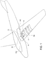
- an ice-breaking device with pulsating membrane DB installed on an aircraft is represented, as well as a corresponding system to supply air to the ice-breaking device.
- Such power supply system comprises an air inlet AI, adapted to receive in operation a flow of air from the outside environment, created by the motion of the aircraft in the air.
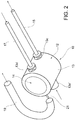
- the system further includes a valve 10 arranged downstream of the outside air inlet AI, and comprising a stator 12 also shown in figures 5a and 5b , and a rotary valve member 14 also shown in figure 4 , which is able to rotate around an axis, indicated at x.
- a valve 10 arranged downstream of the outside air inlet AI, and comprising a stator 12 also shown in figures 5a and 5b , and a rotary valve member 14 also shown in figure 4 , which is able to rotate around an axis, indicated at x.
- the stator or valve body 10 comprises a wall 13 surrounding a cylindrical cavity, wherein the rotor 14 is mounted.
- a wall 13 surrounding a cylindrical cavity, wherein the rotor 14 is mounted.
- four through-openings are made, indicated at 13a, 13b, 13c and 13d, which in the following will be respectively indicated as air loading port, air discharge port, pressurization port and depressurization port, the function of which will become clear in the following description.
- the air loading port 13a is fluidically connected to the air inlet AI through an inlet mouth 13a' (or other type of inlet piping element).
- the air loading port 13a and the pressurization port 13c are arranged at a first level with respect to the rotation axis x of the valve member 14, while the air discharge port 13b and the depressurization port 13d are arranged at a second level with respect to the rotation axis x of the valve member 14, different from the first level.
- the air loading port 13a and the pressurization port 13c are aligned with each other according to a first axis orthogonal to the rotation axis x, while the air discharge port 13b and the depressurization port 13d are aligned with each other according to a second axis orthogonal to the rotation axis x, parallel to the first axis.
- valve member or rotor 14 is operationally connected to an actuator or motor (not shown), controllable to draw the valve member 14 in rotation with respect to the stator 12.
- the valve member 14 has a first and a second passage 14a, 14b, rectilinear and obtained transversely through the body of the valve member.
- the first passage 14a is arranged at the level of the air loading port 13a and of the pressurization port 13c, arranged at a first level with respect to the rotation axis x of the valve member 14, while the second passage 14b is arranged at the level of the air discharge port 13b and the depressurization port 13d.
- the passages 14a and 14b extend orthogonally to the rotation axis x of the valve member 14, angularly staggered from each other, e.g. by an angle of 90°.
- the system also comprises a pressurization channel 15, which at one end is fluidically connected to the pressurization port 13c of the valve 10, and at the opposite end is fluidically connected to an inlet of the pneumatic ice-breaking device.
- the cross-section of the inner opening of the pressurization channel 15 is smaller than the cross-section of the inlet mouth 13a'. Moreover, the pressurization channel 15 and the inlet mouth 13a' extend along the same geometric axis, coinciding with the geometric axis along which the ports 13a and 13c are aligned. Other geometric arrangements are however possible.
- the system also comprises a depressurization channel 17, which at one end is fluidically connected to the depressurization port 13d of the valve 10, and at the opposite end is fluidically connected to an outlet of the pneumatic ice-breaking device.
- An air discharge duct 19 is further provided, which at one end is fluidically connected to the air discharge port 13b of the valve 10, and at the opposite end is fluidically connected to an air outlet AO arranged on the aircraft and positioned so that, in operation, the air pressure thereon is lower than the outside ambient pressure.
- the cross-section of the inner opening of the depressurization channel 17 is smaller than the cross-section of the air discharge duct 19. Moreover, the depressurization channel 17 and an end part of the air discharge duct 19 extend along a same geometric axis, coinciding with the geometric axis along which the openings 13b and 13d are aligned. Other geometric arrangements are however possible.
- the system further comprises a suction pump 21 located at the air discharge port 13b, in particular a Venturi-effect pump, activated by a flow of air coming from the air loading port 13a.
- a suction pump 21 located at the air discharge port 13b, in particular a Venturi-effect pump, activated by a flow of air coming from the air loading port 13a.
- a duct 13e may be provided between the air loading port 13a and the air discharge port 13b, which is designed to supply air from the air loading port to the pump 21.
- a duct outside the stator body 12 may be provided.
- the valve member 14 is able to cyclically rotate between a pressurization position ( figure 6 ), in which the air loading port 13a is fluidically connected to the pressurization port 13c through the first passage 14a while the depressurization port 13d is disconnected from the air discharge port 13b, and a depressurization position ( figure 7 ) in which the depressurization port 13d is fluidically connected to the air discharge port 13b through the second passage 14b while the air loading port 13a is disconnected from the pressurization port 13c.
- an air flow therefore enters from the air inlet AI and arrives at the ice-breaking device DB after having passed through the inlet mouth 13a', the air loading port 13a, the first passage 14a, the pressurization port 13c and the pressurization duct 15; the kinetic energy of the air flow at the air inlet AI is then converted into air pressure at the pneumatic ice-breaking device DB, which is then inflated.
- the ice-breaking device DB is fluidically connected to the air outlet AO through the depressurization duct 17, the depressurization port 13d, the second passage 14b, the air discharge port 13b and the air discharge duct 19; an air flow therefore escapes from the ice-breaking device (which then deflates) as a result of the pressure difference between the ice-breaking device and the air discharge. Moreover, the discharge flow is accelerated by the suction pump 21, increasing the depressurization of the ice-breaking device.
- the rotor feed may be configured to always rotate the valve member in the same direction, or to cyclically reverse the direction of rotation of the valve member. In any case, it is possible to obtain repeated cycles of pressurization and depressurization.
- the motor or actuator of the valve member may be configured to allow an adjustment of the rotation speed of the valve member and thus allow an adjustment of the work cycle of the system.
Landscapes
- Engineering & Computer Science (AREA)
- Mechanical Engineering (AREA)
- General Engineering & Computer Science (AREA)
- Aviation & Aerospace Engineering (AREA)
- Multiple-Way Valves (AREA)
Abstract
Description
- The present invention refers to ice-breaking systems for aircraft.
- Known deicing protection systems, such as the "deicing boot", are of a type generally installed on the surfaces of aircraft (usually the leading edges of the wings and the tail fins), which allows for a mechanical-pneumatic defrosting during the flight.
- Such system is based on rubber chambers (or membranes) mounted on the surfaces to be defrosted. When ice forms, a pneumatic system is activated to cyclically inflate and deflate the membranes. Repeated cycles of expansion and contraction cause cracks in the accumulated ice, which is swept away by the airflow over the surface of the aircraft.
- Known systems use compressed air drawn from the aircraft's propulsion system or from dedicated accumulators; such systems are generally relatively bulky and heavy and have a negative impact on the consumption and performance of the propulsion system. Moreover, being relatively complex, they can require a significant level of maintenance.
-
WO 2013/088319 A1 ,EP 2772459 A2 andUS 2016/296370 A1 describe pneumatic systems based on rotary valve members, which use pneumatic energy generated or stored within the system for their operation.US 2337426 A describes an ice-breaking system that uses a rotary valve member to power ice-breaking devices, which consumes pressurized air generated in the engine nacelles. The use of pressurized air generated or accumulated inside the aircraft also appears inUS 5393014 A andUS 2883129 A . - One of the objects of the present invention is to make available a system to supply air to a pneumatic ice-breaking device that allows for one or more of the aforementioned problems to be at least partially overcome.
- For such purpose, an ice-breaking system for an aircraft is the object of the invention, comprising
- a pneumatic ice-breaking device;
- an air inlet adapted to receive air from the outside environment of the aircraft and an air outlet adapted to discharge air into the outside environment; and
- a motorized valve having an air loading port directly connected to the air inlet and an air discharge port directly connected to the air outlet, said valve being configured to supply air to the pneumatic ice-breaking device in a pulsating way;
- As there are no machines to generate an air flow directly to the valve or for storing pneumatic energy in a reservoir, the "pulsating conversion" of the dynamic pressure of the outside air into static pressure is only possible when the airplane is in motion. By virtue of the motorized valve, the conversion of the dynamic pressure of the outside air into static pressure is cyclic over time and each pressurization cycle is followed by a depressurization cycle; the pressurization cycle of the pneumatic ice-breaking device ("boot") modifies the shape of the latter so as to cause the ice deposited on the outer surface of the same device to break; the depressurization cycle of the "boot" restores the original shape of the latter.
- Unlike the known systems described above, the valve is used to gain advantage from the dynamic pressure of the air outside the moving aircraft by avoiding the consumption of pneumatic energy generated or stored inside the same aircraft.
- According to a specific embodiment, the valve comprises a stator and a motorized valve member rotatably mounted inside the stator,
- wherein the stator has an air loading port and an air discharge port, as well as a pressurization port and a depressurization port adapted to be fluidically connected to the pneumatic ice-breaking device,
- wherein the valve member has a first and a second passage formed transversely therethrough, whereby in operation the valve member is capable of cyclically rotating between a pressurization position, in which the air loading port is fluidically connected to the pressurization port through the first passage while the depressurization port is disconnected from the air discharge port, and a depressurization position in which the depressurization port is fluidically connected to the air discharge port through the second passage while the air loading port is disconnected from the pressurization port.
- Some preferred but non-limiting embodiments will now be described; making reference to the accompanying drawings, wherein:
-
figure 1 is a simplified view of a system according to the invention, installed on an aircraft; -
figures 2 and3 are perspective views showing a valve of the system according to the invention; -
figure 4 is a perspective view showing a valve member of the valve offigures 2 and3 ; -
figures 5a and 5b are perspective views showing a stator of the valve offigures 2 and3 ; and -
figures 6 and 7 are sectioned perspective views showing the valve, respectively in a pressurization position and a depressurization position. - With reference to
figure 1 , an ice-breaking device with pulsating membrane DB installed on an aircraft is represented, as well as a corresponding system to supply air to the ice-breaking device. - Such power supply system comprises an air inlet AI, adapted to receive in operation a flow of air from the outside environment, created by the motion of the aircraft in the air.
- With reference also to
figures 2 and3 , the system further includes avalve 10 arranged downstream of the outside air inlet AI, and comprising astator 12 also shown infigures 5a and 5b , and arotary valve member 14 also shown infigure 4 , which is able to rotate around an axis, indicated at x. - The stator or
valve body 10 comprises awall 13 surrounding a cylindrical cavity, wherein therotor 14 is mounted. On thewall 13, four through-openings are made, indicated at 13a, 13b, 13c and 13d, which in the following will be respectively indicated as air loading port, air discharge port, pressurization port and depressurization port, the function of which will become clear in the following description. - The
air loading port 13a is fluidically connected to the air inlet AI through aninlet mouth 13a' (or other type of inlet piping element). - The
air loading port 13a and thepressurization port 13c are arranged at a first level with respect to the rotation axis x of thevalve member 14, while theair discharge port 13b and thedepressurization port 13d are arranged at a second level with respect to the rotation axis x of thevalve member 14, different from the first level. - In particular, the
air loading port 13a and thepressurization port 13c are aligned with each other according to a first axis orthogonal to the rotation axis x, while theair discharge port 13b and thedepressurization port 13d are aligned with each other according to a second axis orthogonal to the rotation axis x, parallel to the first axis. - The valve member or
rotor 14 is operationally connected to an actuator or motor (not shown), controllable to draw thevalve member 14 in rotation with respect to thestator 12. - The
valve member 14 has a first and asecond passage first passage 14a is arranged at the level of theair loading port 13a and of thepressurization port 13c, arranged at a first level with respect to the rotation axis x of thevalve member 14, while thesecond passage 14b is arranged at the level of theair discharge port 13b and thedepressurization port 13d. - The
passages valve member 14, angularly staggered from each other, e.g. by an angle of 90°. - Other geometric arrangements of the ports of the stator and the passages of the rotor are possible, although the one described above is preferable for the operation of the system.
- The system also comprises a
pressurization channel 15, which at one end is fluidically connected to thepressurization port 13c of thevalve 10, and at the opposite end is fluidically connected to an inlet of the pneumatic ice-breaking device. - The cross-section of the inner opening of the
pressurization channel 15 is smaller than the cross-section of theinlet mouth 13a'. Moreover, thepressurization channel 15 and theinlet mouth 13a' extend along the same geometric axis, coinciding with the geometric axis along which theports - The system also comprises a
depressurization channel 17, which at one end is fluidically connected to thedepressurization port 13d of thevalve 10, and at the opposite end is fluidically connected to an outlet of the pneumatic ice-breaking device. - An
air discharge duct 19 is further provided, which at one end is fluidically connected to theair discharge port 13b of thevalve 10, and at the opposite end is fluidically connected to an air outlet AO arranged on the aircraft and positioned so that, in operation, the air pressure thereon is lower than the outside ambient pressure. - The cross-section of the inner opening of the
depressurization channel 17 is smaller than the cross-section of theair discharge duct 19. Moreover, thedepressurization channel 17 and an end part of theair discharge duct 19 extend along a same geometric axis, coinciding with the geometric axis along which theopenings - The system further comprises a
suction pump 21 located at theair discharge port 13b, in particular a Venturi-effect pump, activated by a flow of air coming from theair loading port 13a. For such purpose, in thewall 13 of thestator 12, aduct 13e may be provided between theair loading port 13a and theair discharge port 13b, which is designed to supply air from the air loading port to thepump 21. Alternatively, a duct outside thestator body 12 may be provided. - In operation, following a command given to the relevant motor or actuator, the
valve member 14 is able to cyclically rotate between a pressurization position (figure 6 ), in which theair loading port 13a is fluidically connected to thepressurization port 13c through thefirst passage 14a while thedepressurization port 13d is disconnected from theair discharge port 13b, and a depressurization position (figure 7 ) in which thedepressurization port 13d is fluidically connected to theair discharge port 13b through thesecond passage 14b while theair loading port 13a is disconnected from thepressurization port 13c. - At each pressurization stage, an air flow therefore enters from the air inlet AI and arrives at the ice-breaking device DB after having passed through the
inlet mouth 13a', theair loading port 13a, thefirst passage 14a, thepressurization port 13c and thepressurization duct 15; the kinetic energy of the air flow at the air inlet AI is then converted into air pressure at the pneumatic ice-breaking device DB, which is then inflated. - At each depressurization stage, the ice-breaking device DB is fluidically connected to the air outlet AO through the
depressurization duct 17, thedepressurization port 13d, thesecond passage 14b, theair discharge port 13b and theair discharge duct 19; an air flow therefore escapes from the ice-breaking device (which then deflates) as a result of the pressure difference between the ice-breaking device and the air discharge. Moreover, the discharge flow is accelerated by thesuction pump 21, increasing the depressurization of the ice-breaking device. - The rotor feed may be configured to always rotate the valve member in the same direction, or to cyclically reverse the direction of rotation of the valve member. In any case, it is possible to obtain repeated cycles of pressurization and depressurization.
- The motor or actuator of the valve member may be configured to allow an adjustment of the rotation speed of the valve member and thus allow an adjustment of the work cycle of the system.
Claims (8)
- An ice-breaking system for an aircraft, comprising- a pneumatic ice-breaking device (DB);- an air inlet (AI) adapted to receive air from the environment outside the aircraft and an air outlet (AO) adapted to discharge air into the outside environment; and- a motorized valve (10) having an air loading port (13a) connected to the air inlet (AI) and an air discharge port (13b) connected to the air outlet (AO), said valve being configured to supply air to the pneumatic ice-breaking device (DB) in a pulsating way;wherein, when the aircraft is in motion, the kinetic energy of the air at the air inlet (AI) and originating from the relative motion between the air and the aircraft is converted into air pressure at the pneumatic ice-breaking device (DB), and wherein the air outlet (AO) is positioned so that when the aircraft is in motion the air pressure at the air outlet (AO) is lower than the outside ambient pressure.
- A system according to claim 1, wherein the valve (10) comprises a stator (12) and a motorized valve member (14) rotatably mounted inside the stator (12),
wherein the stator (12) has an air loading port (13a) and an air discharge port (13b), as well as a pressurization port (13c) and a depressurization port (13d), fluidically connected to the pneumatic ice-breaking device (DB),
wherein the valve member (14) has a first and a second passage (14a, 14b) formed transversely therethrough, whereby in operation the valve member (14) is able to cyclically rotate between a pressurization position, in which the air loading port (13a) is fluidically connected to the pressurization port (13c) through the first passage (14a) while the depressurization port (13d) is disconnected from the air discharge port (13b), and a depressurization position in which the depressurization port (13d) is fluidically connected to the air discharge port (13b) through the second passage (14b) while the air loading port (13a) is disconnected from the pressurization port (13c). - A system according to claim 2, wherein the air loading port (13a), the pressurization port (13c) and the first passage (14a) are arranged at a first level with respect to the rotation axis (x) of the valve member (14), and the air discharge port (13b), the depressurization port (13d) and the second passage (14b) are arranged at a second level with respect to the rotation axis (x) of the valve member (14), different from the first level.
- A system according to claim 3, wherein the first passage (14a) and the second passage (14b) are rectilinear and extend orthogonally to the rotation axis (x) of the valve member (14), angularly staggered with each other.
- A system according to any of the preceding claims, further comprising a suction pump (21) arranged at the air discharge port (13b).
- A system according to claim 5, wherein the suction pump (21) is a Venturi-effect pump, said pump being driven with air from the air loading port (13a).
- A system according to claim 6, wherein in the stator (12) a duct (13e) is provided, formed between the air loading port (13a) and the air discharge port (13b), said duct being provided for feeding air from the air loading port (13a) to the Venturi-effect pump.
- A system according to any of the preceding claims, wherein the pneumatic ice-breaking device (DB) is an ice-breaking device with pulsating membrane.
Applications Claiming Priority (1)
| Application Number | Priority Date | Filing Date | Title |
|---|---|---|---|
| IT102017000121327A IT201700121327A1 (en) | 2017-10-25 | 2017-10-25 | System to feed a pneumatic icebreaker device with external air. |
Publications (1)
| Publication Number | Publication Date |
|---|---|
| EP3476738A1 true EP3476738A1 (en) | 2019-05-01 |
Family
ID=61224435
Family Applications (1)
| Application Number | Title | Priority Date | Filing Date |
|---|---|---|---|
| EP18201664.2A Withdrawn EP3476738A1 (en) | 2017-10-25 | 2018-10-22 | An ice-breaking system for an aircraft |
Country Status (3)
| Country | Link |
|---|---|
| US (1) | US11117671B2 (en) |
| EP (1) | EP3476738A1 (en) |
| IT (1) | IT201700121327A1 (en) |
Cited By (1)
| Publication number | Priority date | Publication date | Assignee | Title |
|---|---|---|---|---|
| EP4580945A1 (en) * | 2022-08-31 | 2025-07-09 | Tusas- Turk Havacilik Ve Uzay Sanayii Anonim Sirketi | An anti-icing system |
Families Citing this family (1)
| Publication number | Priority date | Publication date | Assignee | Title |
|---|---|---|---|---|
| CN113148182A (en) * | 2021-05-31 | 2021-07-23 | 中航(成都)无人机系统股份有限公司 | Unmanned aerial vehicle and wing defroster thereof |
Citations (10)
| Publication number | Priority date | Publication date | Assignee | Title |
|---|---|---|---|---|
| US2168328A (en) * | 1937-12-04 | 1939-08-08 | Walter S Diehl | Deicing means for airplanes |
| US2337426A (en) | 1940-01-19 | 1943-12-21 | Goodrich Co B F | System of inflation and apparatus for operating the same |
| US2515519A (en) * | 1943-08-11 | 1950-07-18 | Bendix Aviat Corp | Air distributor valve and system for the elimination of ice from aircraft |
| US2753138A (en) * | 1952-11-19 | 1956-07-03 | Bendix Aviat Corp | Operating mechanism for inflatable ice eliminating system |
| US2883129A (en) | 1955-04-19 | 1959-04-21 | Bendix Aviat Corp | Pressure and vacuum system for operating inflatable elements |
| FR1439135A (en) * | 1965-04-05 | 1966-05-20 | Bendix Corp | Defrost kit |
| US5393014A (en) | 1992-09-30 | 1995-02-28 | The B. F. Goodrich Company | Pneumatic deicing distribution valve and system |
| WO2013088319A1 (en) | 2011-12-14 | 2013-06-20 | Koninklijke Philips Electronics N.V. | Reversing valve and high frequency oscillation airflow generator |
| EP2772459A2 (en) | 2013-02-27 | 2014-09-03 | Kabushiki Kaisha Toshiba | Paper sheet pickup device and paper sheet processing apparatus |
| US20160296370A1 (en) | 2015-04-13 | 2016-10-13 | Novartis Ag | High speed pneumatic valve |
Family Cites Families (1)
| Publication number | Priority date | Publication date | Assignee | Title |
|---|---|---|---|---|
| US6082667A (en) * | 1995-04-21 | 2000-07-04 | Haggard; Roy A. | Inflated wing |
-
2017
- 2017-10-25 IT IT102017000121327A patent/IT201700121327A1/en unknown
-
2018
- 2018-10-22 EP EP18201664.2A patent/EP3476738A1/en not_active Withdrawn
- 2018-10-24 US US16/169,871 patent/US11117671B2/en not_active Expired - Fee Related
Patent Citations (10)
| Publication number | Priority date | Publication date | Assignee | Title |
|---|---|---|---|---|
| US2168328A (en) * | 1937-12-04 | 1939-08-08 | Walter S Diehl | Deicing means for airplanes |
| US2337426A (en) | 1940-01-19 | 1943-12-21 | Goodrich Co B F | System of inflation and apparatus for operating the same |
| US2515519A (en) * | 1943-08-11 | 1950-07-18 | Bendix Aviat Corp | Air distributor valve and system for the elimination of ice from aircraft |
| US2753138A (en) * | 1952-11-19 | 1956-07-03 | Bendix Aviat Corp | Operating mechanism for inflatable ice eliminating system |
| US2883129A (en) | 1955-04-19 | 1959-04-21 | Bendix Aviat Corp | Pressure and vacuum system for operating inflatable elements |
| FR1439135A (en) * | 1965-04-05 | 1966-05-20 | Bendix Corp | Defrost kit |
| US5393014A (en) | 1992-09-30 | 1995-02-28 | The B. F. Goodrich Company | Pneumatic deicing distribution valve and system |
| WO2013088319A1 (en) | 2011-12-14 | 2013-06-20 | Koninklijke Philips Electronics N.V. | Reversing valve and high frequency oscillation airflow generator |
| EP2772459A2 (en) | 2013-02-27 | 2014-09-03 | Kabushiki Kaisha Toshiba | Paper sheet pickup device and paper sheet processing apparatus |
| US20160296370A1 (en) | 2015-04-13 | 2016-10-13 | Novartis Ag | High speed pneumatic valve |
Cited By (1)
| Publication number | Priority date | Publication date | Assignee | Title |
|---|---|---|---|---|
| EP4580945A1 (en) * | 2022-08-31 | 2025-07-09 | Tusas- Turk Havacilik Ve Uzay Sanayii Anonim Sirketi | An anti-icing system |
Also Published As
| Publication number | Publication date |
|---|---|
| US20190329893A1 (en) | 2019-10-31 |
| US11117671B2 (en) | 2021-09-14 |
| IT201700121327A1 (en) | 2019-04-25 |
Similar Documents
| Publication | Publication Date | Title |
|---|---|---|
| CN113415412A (en) | Wide-speed-range jet control aircraft | |
| CN110582635B (en) | Pressure supply system for pneumatically activatable pneumatics of a rotor blade of a wind turbine | |
| US11117671B2 (en) | Ice-breaking system for an aircraft | |
| EP1931566B1 (en) | Oscillating vane actuator apparatus and method for active flow control | |
| CN106523158B (en) | Air intake device and operating method for a turboshaft engine | |
| WO2008057586A2 (en) | Oscillating vane actuator apparatus and method for active flow control | |
| AU2014210666B2 (en) | Active Bleed For Airfoils | |
| CN114013557B (en) | Cavity body air-compression type water-entering combined load-reducing device | |
| CN113682466A (en) | Aircraft non-control surface flight control method based on synthetic double-jet flow field control | |
| EP0590553A1 (en) | Pneumatic deicing distribution valve and system | |
| KR20110117835A (en) | Propulsion efficiency improvement device of duct type propeller using nozzle | |
| US7575196B2 (en) | Ice protection system and method including a plurality of segmented sub-areas and a cyclic diverter valve | |
| WO2005054685A1 (en) | Method for increasing a blade performance (variants) | |
| US11629702B2 (en) | Device for draining humidity in wind turbines | |
| CN108163213B (en) | Multistage supercharging fan-blade-free air propulsion method and propulsion device | |
| US2753138A (en) | Operating mechanism for inflatable ice eliminating system | |
| US7246529B1 (en) | Oscillating vane actuator apparatus and method for active flow control | |
| CN105782135A (en) | Pneumatic vacuum generator | |
| US11754041B2 (en) | Quick adaptation of wind turbine blade flow regulation | |
| CN113955055B (en) | A composite load-reducing device for an aircraft body | |
| CN201647123U (en) | inflatable flexible flap | |
| RU85446U1 (en) | AIRPLANE WITH AERODYNAMICALLY CARRYING HOUSING | |
| US12066008B2 (en) | Device for controlling humidity in wind turbines | |
| EP4382427A1 (en) | Environmental control system including mixed-flow turbine | |
| EP4603389A2 (en) | Pneumatic deicing system integrated with an air management system and advanced inlet air connection valve |
Legal Events
| Date | Code | Title | Description |
|---|---|---|---|
| PUAI | Public reference made under article 153(3) epc to a published international application that has entered the european phase |
Free format text: ORIGINAL CODE: 0009012 |
|
| STAA | Information on the status of an ep patent application or granted ep patent |
Free format text: STATUS: THE APPLICATION HAS BEEN PUBLISHED |
|
| AK | Designated contracting states |
Kind code of ref document: A1 Designated state(s): AL AT BE BG CH CY CZ DE DK EE ES FI FR GB GR HR HU IE IS IT LI LT LU LV MC MK MT NL NO PL PT RO RS SE SI SK SM TR |
|
| AX | Request for extension of the european patent |
Extension state: BA ME |
|
| STAA | Information on the status of an ep patent application or granted ep patent |
Free format text: STATUS: REQUEST FOR EXAMINATION WAS MADE |
|
| 17P | Request for examination filed |
Effective date: 20191024 |
|
| RBV | Designated contracting states (corrected) |
Designated state(s): AL AT BE BG CH CY CZ DE DK EE ES FI FR GB GR HR HU IE IS IT LI LT LU LV MC MK MT NL NO PL PT RO RS SE SI SK SM TR |
|
| STAA | Information on the status of an ep patent application or granted ep patent |
Free format text: STATUS: EXAMINATION IS IN PROGRESS |
|
| 17Q | First examination report despatched |
Effective date: 20210329 |
|
| STAA | Information on the status of an ep patent application or granted ep patent |
Free format text: STATUS: THE APPLICATION IS DEEMED TO BE WITHDRAWN |
|
| 18D | Application deemed to be withdrawn |
Effective date: 20210810 |