EP3476692A1 - "steer by wire" road vehicle steering system provided with a telescopic support element for the steering wheel - Google Patents
"steer by wire" road vehicle steering system provided with a telescopic support element for the steering wheel Download PDFInfo
- Publication number
- EP3476692A1 EP3476692A1 EP18202958.7A EP18202958A EP3476692A1 EP 3476692 A1 EP3476692 A1 EP 3476692A1 EP 18202958 A EP18202958 A EP 18202958A EP 3476692 A1 EP3476692 A1 EP 3476692A1
- Authority
- EP
- European Patent Office
- Prior art keywords
- steering wheel
- steering
- steering system
- electric motor
- outer ring
- Prior art date
- Legal status (The legal status is an assumption and is not a legal conclusion. Google has not performed a legal analysis and makes no representation as to the accuracy of the status listed.)
- Granted
Links
Images








Classifications
-
- B—PERFORMING OPERATIONS; TRANSPORTING
- B62—LAND VEHICLES FOR TRAVELLING OTHERWISE THAN ON RAILS
- B62D—MOTOR VEHICLES; TRAILERS
- B62D1/00—Steering controls, i.e. means for initiating a change of direction of the vehicle
- B62D1/02—Steering controls, i.e. means for initiating a change of direction of the vehicle vehicle-mounted
- B62D1/04—Hand wheels
- B62D1/10—Hubs; Connecting hubs to steering columns, e.g. adjustable
- B62D1/105—Non-rotatable hubs, e.g. the central part of the steering wheel not rotating
-
- B—PERFORMING OPERATIONS; TRANSPORTING
- B62—LAND VEHICLES FOR TRAVELLING OTHERWISE THAN ON RAILS
- B62D—MOTOR VEHICLES; TRAILERS
- B62D5/00—Power-assisted or power-driven steering
- B62D5/04—Power-assisted or power-driven steering electrical, e.g. using an electric servo-motor connected to, or forming part of, the steering gear
- B62D5/0409—Electric motor acting on the steering column
-
- B—PERFORMING OPERATIONS; TRANSPORTING
- B62—LAND VEHICLES FOR TRAVELLING OTHERWISE THAN ON RAILS
- B62D—MOTOR VEHICLES; TRAILERS
- B62D1/00—Steering controls, i.e. means for initiating a change of direction of the vehicle
- B62D1/02—Steering controls, i.e. means for initiating a change of direction of the vehicle vehicle-mounted
- B62D1/16—Steering columns
- B62D1/18—Steering columns yieldable or adjustable, e.g. tiltable
- B62D1/181—Steering columns yieldable or adjustable, e.g. tiltable with power actuated adjustment, e.g. with position memory
-
- B—PERFORMING OPERATIONS; TRANSPORTING
- B62—LAND VEHICLES FOR TRAVELLING OTHERWISE THAN ON RAILS
- B62D—MOTOR VEHICLES; TRAILERS
- B62D5/00—Power-assisted or power-driven steering
- B62D5/001—Mechanical components or aspects of steer-by-wire systems, not otherwise provided for in this maingroup
-
- B—PERFORMING OPERATIONS; TRANSPORTING
- B62—LAND VEHICLES FOR TRAVELLING OTHERWISE THAN ON RAILS
- B62D—MOTOR VEHICLES; TRAILERS
- B62D5/00—Power-assisted or power-driven steering
- B62D5/001—Mechanical components or aspects of steer-by-wire systems, not otherwise provided for in this maingroup
- B62D5/005—Mechanical components or aspects of steer-by-wire systems, not otherwise provided for in this maingroup means for generating torque on steering wheel or input member, e.g. feedback
- B62D5/006—Mechanical components or aspects of steer-by-wire systems, not otherwise provided for in this maingroup means for generating torque on steering wheel or input member, e.g. feedback power actuated
-
- B—PERFORMING OPERATIONS; TRANSPORTING
- B62—LAND VEHICLES FOR TRAVELLING OTHERWISE THAN ON RAILS
- B62D—MOTOR VEHICLES; TRAILERS
- B62D5/00—Power-assisted or power-driven steering
- B62D5/04—Power-assisted or power-driven steering electrical, e.g. using an electric servo-motor connected to, or forming part of, the steering gear
- B62D5/0403—Power-assisted or power-driven steering electrical, e.g. using an electric servo-motor connected to, or forming part of, the steering gear characterised by constructional features, e.g. common housing for motor and gear box
-
- B—PERFORMING OPERATIONS; TRANSPORTING
- B62—LAND VEHICLES FOR TRAVELLING OTHERWISE THAN ON RAILS
- B62D—MOTOR VEHICLES; TRAILERS
- B62D5/00—Power-assisted or power-driven steering
- B62D5/04—Power-assisted or power-driven steering electrical, e.g. using an electric servo-motor connected to, or forming part of, the steering gear
- B62D5/0442—Conversion of rotational into longitudinal movement
- B62D5/0454—Worm gears
-
- B—PERFORMING OPERATIONS; TRANSPORTING
- B62—LAND VEHICLES FOR TRAVELLING OTHERWISE THAN ON RAILS
- B62D—MOTOR VEHICLES; TRAILERS
- B62D5/00—Power-assisted or power-driven steering
- B62D5/04—Power-assisted or power-driven steering electrical, e.g. using an electric servo-motor connected to, or forming part of, the steering gear
- B62D5/0457—Power-assisted or power-driven steering electrical, e.g. using an electric servo-motor connected to, or forming part of, the steering gear characterised by control features of the drive means as such
- B62D5/0481—Power-assisted or power-driven steering electrical, e.g. using an electric servo-motor connected to, or forming part of, the steering gear characterised by control features of the drive means as such monitoring the steering system, e.g. failures
-
- B—PERFORMING OPERATIONS; TRANSPORTING
- B62—LAND VEHICLES FOR TRAVELLING OTHERWISE THAN ON RAILS
- B62D—MOTOR VEHICLES; TRAILERS
- B62D6/00—Arrangements for automatically controlling steering depending on driving conditions sensed and responded to, e.g. control circuits
- B62D6/08—Arrangements for automatically controlling steering depending on driving conditions sensed and responded to, e.g. control circuits responsive only to driver input torque
- B62D6/10—Arrangements for automatically controlling steering depending on driving conditions sensed and responded to, e.g. control circuits responsive only to driver input torque characterised by means for sensing or determining torque
-
- G—PHYSICS
- G01—MEASURING; TESTING
- G01L—MEASURING FORCE, STRESS, TORQUE, WORK, MECHANICAL POWER, MECHANICAL EFFICIENCY, OR FLUID PRESSURE
- G01L5/00—Apparatus for, or methods of, measuring force, work, mechanical power, or torque, specially adapted for specific purposes
- G01L5/22—Apparatus for, or methods of, measuring force, work, mechanical power, or torque, specially adapted for specific purposes for measuring the force applied to control members, e.g. control members of vehicles, triggers
- G01L5/221—Apparatus for, or methods of, measuring force, work, mechanical power, or torque, specially adapted for specific purposes for measuring the force applied to control members, e.g. control members of vehicles, triggers to steering wheels, e.g. for power assisted steering
Definitions
- the invention relates to a " steer by wire” road vehicle steering system.
- a steering system which fulfils the function of controlling the steering angle, namely the angle existing between the direction of the front wheels (i.e. the plane of rotation of the front wheels and the longitudinal axis of the road vehicle.
- the steering system comprises a control shaft, which is arranged crosswise, is mechanically connected, at its opposite ends, to the hubs of the front wheels, and is mounted in an axially sliding manner in order to change the steering angle.
- the steering system comprises a steering wheel, which is mounted in a rotary manner inside the passenger compartment and is mechanically connected to the control shaft by means of a transmission device so that the rotation of the steering wheel determines an axial translation of the control shaft and, hence, a corresponding variation of the steering angle.
- Patent application DE102015224602A1 describes a steering system of a road vehicle comprising a support element, which, on one side, can be rigidly fixed on the inside of the vehicle and, on the other side, is connected to a steering wheel so as to support the steering wheel; the support element is telescopic so as to vary its axial size along ta rotation axis of the steering wheel in order to change the axial position of the steering wheel.
- the object of the invention is to provide a " steer by wire” road vehicle steering system, which can be manufactured in a simple and economic fashion and, at the same time, is compact, effective and efficient.
- number 1 indicates, as a whole, a road vehicle provided with two front steering wheels 2 and two rear drive wheels 3, which receive the torque from a powertrain system.
- the road vehicle 1 comprises a steering system 4, which fulfils the function of controlling the steering angle, namely the angle existing between the direction of the front wheels 2 (i.e. the plane of rotation of the front wheels 2) and the longitudinal axis of the road vehicle 1.
- the steering system 4 comprises a steering mechanism 5, which can be operated so as to change the steering angle, is arranged crosswise and consists of a central rod, which can axially slide and is mechanically connected to the fork ends of the front wheels 2 through articulated tie rods. Furthermore, the steering system 4 comprises a steering wheel 6, which is mounted in a rotary manner inside a passenger compartment and is electronically (virtually) connected to the steering mechanism 5 by means of an electronic transmission device 7 (without mechanical connection) so that the rotation of the steering wheel 6 determines an axial translation of the steering mechanism 5 and, hence, a corresponding variation of the steering angle. In other words, there is no mechanical connection between the steering mechanism 5 and the steering wheel 6 and the transmission device 7 only creates a functional (not mechanical) connection between the steering mechanism 5 and the steering wheel 6.
- the transmission device 7 comprises a sensor 8, which detects in real time the angular position of the steering wheel 6 and the torque applied by the driver to the steering wheel 6; obviously, the sensor 8 is capable of determining the angular position of the steering wheel 6 in an extremely safe manner by carrying out different independent and redundant reading operations aimed at reading the angular position of the steering wheel 6. It should be pointed out that the sensor 8 can be directly coupled, in a mechanical manner, to the steering wheel 6 or to any other part that is angularly integral to the steering wheel 6.
- the transmission device 7 comprises an actuator device 9, which operates the steering mechanism 5 so as to control the steering of the front steering wheels 2 of the road vehicle 1 and comprises an electric motor 10 and a transmission 11, which mechanically connects the electric motor 10 to the steering mechanism 5.
- the electric motor 10 namely, the actuator device 9) is mechanically completely independent of and separate from the steering wheel 6 and is designed to control the steering of the front steering wheels 2 of the road vehicle 1 without any type of mechanical force/torque coming from the steering wheel 6.
- the transmission device 7 comprises an electronic control unit (“ECU") 12, which is connected to the position sensor 8 so as to receive the reading of the angular position of the steering wheel 6 and is designed to control the electric motor 10 of the actuator device 9 so as to adjust the steering of the front steering wheels 2 of the road vehicle 1 based on the angular position of the steering wheel 6.
- the control unit 12 can physically consist of one single device or of different devices separated from one another and communicating with one another through the CAN network of the road vehicle 1.
- the steering wheel 6 is mounted so as to rotate around a rotation axis 13.
- the entire steering wheel 6 i.e. both the central hub 14 and an outer ring 15
- the central hub 14 of the steering wheel 6 is fixed (i.e. it does not rotate around the rotation axis 13)
- the outer ring 15 of the steering wheel 6 is mounted so as to rotate around the rotation axis 13.
- the transmission device 7 of the steering system 4 comprises an electric motor 16, which is directly connected to the steering wheel 6 so as to apply a variable feedback torque to the steering wheel 6 (to the outer ring 15 of the steering wheel 6); in other words, the function of the electric motor 16 is that of applying to the steering wheel 6 (to the outer ring 15 of the steering wheel 6) a variable torque that transmits to the driver torque sensations that are similar to the torque sensations of a traditional steering wheel mechanically connected to the steering wheels.
- the electric motor 16 comprises a stator 17, which does not rotate, and a rotor 18, which can rotate relative to the stator 17 around the rotation axis 13 (namely, is coaxial to the steering wheel 6) and is mechanically connected to the steering wheel 6 (to the outer ring 15 of the steering wheel 6) so as to apply a variable feedback torque to the steering wheel 6. Furthermore, the electric motor 16 supports the steering wheel 6, i.e. the steering wheel 6 is mounted on the electric motor 16; as a consequence, the steering wheel 6 (the outer ring 15 of the steering wheel 6) is rigidly integral to the rotor 18 of the electric motor 16 and is supported by the rotor 18 of the electric motor 16.
- the rotor 18 is internal and, therefore, it is radially arranged on the inside of the stator 17.
- the rotor 18 of the electric motor 16 comprises a shaft 19, which supports the steering wheel 6; in particular, the bearings 20, which support the rotor 18 and are interposed between the rotor 18 and the stator 17, are preferably coupled to the shaft 19 of the rotor 18.
- the rotor 18 is external and, therefore, it is radially arranged on the outside of the stator 17.
- the rotor 18 of the electric motor 16 generally (though, not necessarily) is without shaft.
- This embodiment is particularly advantageous when the central hub 14 of the steering wheel 6 is fixed (i.e. does not rotate around the rotation axis 13) and the sole outer ring 15 of the steering wheel 6 can rotate around the rotation axis 13; indeed, in this embodiment, the central hub 14 of the steering wheel 6 can be directly connected to the stator 17 of the electric motor 16 (i.e.
- the central hub 14 of the steering wheel 6 can be rigidly constrained to the stator 17 of the electric motor 16), whereas the outer ring 15 of the steering wheel 6 can be directly connected to the rotor 18 of the electric motor 16 (i.e. the outer ring 15 of the steering wheel 6 can be rigidly constrained to the rotor 18 of the electric motor 16).
- the transmission device 7 of the steering system 4 comprises a support element 21, which, on one side can be rigidly fixed on the inside of the road vehicle 1 (in particular, to the dashboard of the road vehicle 1) and, on the other side, is rigidly connected to the stator 17 of the electric motor 16 so as to support the electric motor 16.
- the support element 21 is the mounting means through which the electric motor 16 (and, hence, the steering wheel 6 supported by the electric motor 16) is installed and fixed on board the road vehicle 1.
- the support element 21 is telescopic so as to vary its axial size along the rotation axis 13 in order to change the axial position of the electric motor 16 and, hence, of the steering wheel 6.
- the support element 21 comprises an outer tubular body 22, which can be rigidly fixed on the inside of the vehicle 1 and is internally hollow, namely has, on the inside, a chamber 23, which is open on one side (facing the electric motor 16); furthermore, the support element 21 comprises an inner body 24, which is rigidly connected to the stator 17 of the electric motor 16 (i.e. supports the stator 17 of the electric motor 16), is partially arranged inside the outer body 22 (i.e. in the chamber 23 of the outer body 22), and can axially slide relative to the outer body 22.
- the inner body 24 can only slide axially relative to the outer body 22 and, therefore, cannot make any rotation relative to the outer body 22.
- the outer body 22 is provided with a bracket 25, which is used to fix the outer body 22 (hence, the support element 21) to the dashboard of the road vehicle 1.
- the support element 21 comprises an actuator device 26, which is arranged on the inside of the outer body 22 (i.e. is housed in the chamber 23 of the outer body 22) and is designed to axially translate the inner body 24 relative to the outer body 22.
- the actuator device 26 always has the function of stopping (forbidding) the axial translation between the two bodies 22 and 24, so as to make sure that, in use, the steering wheel 6 remains still in a predefined axial position; furthermore, the actuator device 26 can be active, i.e. have an (electric) motor, which causes an axial translation movement of the inner body 24 relative to the outer body 22, or it can be passive, i.e. need the manual intervention of the driver in order to cause an axial translation movement of the inner body 24 relative to the outer body 22.
- the actuator device 26 is active and comprises an electric motor, which is integral to the outer body 22 and causes the rotation of a worm screw, on which an abutment is screwed, which is integral to the inner body 24.
- the stator 17 of the electric motor 16 has, at the centre, a cable-leading through duct 27, which is coaxial to the rotation axis 13; similarly, the inner body 24 of the support element 21 also has a cable-leading through duct 28, which is elbow-shaped (i.e. "L"-shaped) and has an opening, which is obtained through a base wall of the inner body 24, faces and is coaxial to the cable-leading duct 27, and another opposite opening, which is obtained through a side wall of the inner body 24.
- a cabling 29 i.e.
- a set of electrical cables grouped together to form one single bundle is provided, which originates from the central hub 14 of the steering wheel 6 and is arranged through the cable-leading ducts 27 and 28 so as to electrically connect the steering wheel 6 to the rest of the road vehicle 1.
- the presence of the cable-leading duct 27 inside the stator 17 of the electric motor 16 is particularly advantageous when, in the electric motor 16, the rotor 18 is external (according to figure 7 ), but it is also possible when, in the electric motor 16, the rotor 18 is internal.
- the transmission device 7 of the steering system 4 comprises the electric motor 16, which applies the feedback torque to the steering wheel 6; in the alternative embodiment shown in figure 9 , the transmission device 7 of the steering system 4 has no electric motor 16 and, therefore, the steering wheel 6 is directly connected to the inner body 24 of the support element 21; in particular, there is a shaft that, on one side, is rigidly connected to the steering wheel 6 and, on the opposite side, is connected to the inner body 24 of the support element 21 through bearings.
- the support element 21 is coaxial to the electric motor 16 and to the steering wheel 6; in the alternative embodiment shown in figure 10 , the support element 21 is not aligned with the electric motor 16 and with the steering wheel 6 and is mounted lower than the electric motor 16 and the steering wheel 6; the lack of alignment between the support element 21 and the electric motor 16 as well as the steering wheel 6 increases the space available in the part of dashboard above the support element 21 (since the bracket 25 can be placed lower), thus creating a larger space for information devices (control panel, screens) or other devices to be installed in the upper part of the dashboard in front of the driver.
- the transmission device 7 of the steering system 4 comprises a mechanical limit stop device 30, which is coupled to the steering wheel 6 and limits, in both directions, the maximum angular width of the rotation of the steering wheel 6 around the rotation axis 13, so that the steering wheel 6 can make, on the whole, a rotation around the rotation axis 13 that is greater than 360°.
- the fact that the steering wheel 6 is allowed to rotate, on the whole, over more than 360° ensures (when desired) a high steering "reduction", namely in order to avoid (when desired) a too direct steering (which is ideal when driving on a race track, but is not suitable for everyday driving in traffic).
- the limit stop device 30 comprises a groove 31, which is wound in a spiral around the rotation axis 13 over more than 360° and has, at the two opposite ends, two abutments 32, which define respective stop strikers; in other words, the groove 31 extends in a spiral around the rotation axis 13 over more than 360° from an abutment 32 to the opposite abutment 32.
- the groove 31 could extend around the rotation axis 13 over approximately 720° (i.e. two complete rotations of the steering wheel 6) or over approximately 1080° (i.e. three complete rotations of the steering wheel 6).
- the limit stop device 30 comprises a pin 33, which is arranged inside the groove 31 so as to engage and follow the groove 31 from an abutment 32 up to the opposite abutment 32; in other words, the pin 33 is inside the groove 31 and is forced to remain inside the groove 31, thus covering the entire extension of the groove 31 from an abutment 32 to the opposite abutment 32.
- one between the groove 31 and the pin 33 is angularly integral to the steering wheel 6 (hence, rotates in an angularly integral manner with the steering wheel 6), whereas the other one between the groove 31 and the pin 33 is angularly integral to a part that does not rotate together with the steering wheel 6 (in particular, is angularly integral to the inner body 24 of the support element 21).
- the groove 31 is angularly integral to the steering wheel 6, whereas the pin 33 is angularly integral to a part that does not rotate with the steering wheel 6 (i.e.
- the pin 33 is angularly integral to the steering wheel 6, whereas the groove 31 is angularly integral to a part that does not rotate with the steering wheel 6 (i.e. is angularly integral to the inner body 24 of the support element 21).
- one between the groove 31 and the pin 33 can axially slide relative to the steering wheel 6.
- the groove 31 can axially slide relative to the steering wheel 6 or the pin 33 can axially slide relative to the steering wheel 6.
- the groove 31 is angularly integral to the steering wheel 6 (in particular, to a shaft 34 coaxial to the rotation axis 13 which rigidly supports at least the outer ring 15 of the steering wheel 6) and can also axially slide relative to the steering wheel 6 (in particular, relative to the shaft 34); as a consequence, the pin 33 is rigidly connected to a part that does not rotate with the steering wheel 6 (i.e. is angularly integral to the inner body 24 of the support element 21).
- the groove 31 is coupled to the steering wheel 6 (in particular, to the shaft 34) through a splined coupling, which constrains in an angular manner, enabling, at the same time, an axial sliding.
- the groove 31 can be mounted on any part that is angularly integral to the steering wheel 6 (i.e. that rotates around the rotation axis 13 together with the steering wheel 6), for example the shaft 34 coaxial to the rotation axis 13 which rigidly supports at least the outer ring 15 of the steering wheel 6, the rotor 18 of the electric motor 16 or the steering wheel 6 itself.
- the groove 31 is angularly integral to the steering wheel 6 (in particular, to a shaft 34 coaxial to the rotation axis 13 which rigidly supports at least the outer ring 15 of the steering wheel 6) and is also rigidly constrained to the steering wheel 6 (in particular, to the shaft 34); as a consequence, the pin 33 is angularly integral and can axially slide relative to a part that does not rotate with the steering wheel 6 (i.e. is angularly integral and can axially slide relative to the inner body 24 of the support element 21). In other words, the pin 33 can axially slide, but cannot rotate relative to a part that does not rotate together with the steering wheel 6 (i.e. relative to the inner body 24 of the support element 21).
- the steering system 4 described above has numerous advantages.
- the steering system 4 described above is particularly compact, effective and efficient, since the total number of components of the transmission device 7 is reduced to a minimum.
- the steering wheel 6 is directly supported by the electric motor 16, which, hence, applies the feedback torque to the steering wheel 6 without intermediate elements.
- the support element 21 is extremely simple, functional and compact, as it has a tubular shape housing, on the inside, the actuator device 26, which regulates the axial movements of the steering wheel 6.
- the support element 21 allows the steering wheel 6 to cover a much wider axial stroke, which can get up to 250 mm, without particular constructive complications (also thanks to the absence of a connection shaft towards the steering mechanism 5).
Landscapes
- Engineering & Computer Science (AREA)
- Chemical & Material Sciences (AREA)
- Combustion & Propulsion (AREA)
- Transportation (AREA)
- Mechanical Engineering (AREA)
- Power Steering Mechanism (AREA)
Abstract
Description
- This patent application claims priority from Italian patent application no.
102017000121876 filed on 26/10/2017 - The invention relates to a "steer by wire" road vehicle steering system.
- In a road vehicle, a steering system is provided, which fulfils the function of controlling the steering angle, namely the angle existing between the direction of the front wheels (i.e. the plane of rotation of the front wheels and the longitudinal axis of the road vehicle. The steering system comprises a control shaft, which is arranged crosswise, is mechanically connected, at its opposite ends, to the hubs of the front wheels, and is mounted in an axially sliding manner in order to change the steering angle. Furthermore, the steering system comprises a steering wheel, which is mounted in a rotary manner inside the passenger compartment and is mechanically connected to the control shaft by means of a transmission device so that the rotation of the steering wheel determines an axial translation of the control shaft and, hence, a corresponding variation of the steering angle.
- In the automotive industry there is a tendency towards an increasing use of "drive by wire" systems, in which the direct mechanical connection between the controls of the vehicle (steering wheel, accelerator, brake clutch, gear stick) and the actuators of the vehicle (steering tie rod, throttle valve, brake pump...) is replaced by a (virtual) electronic connection, which involves the use of a position sensor, which reads the position of a control of the vehicle and communicates it to an electronic control unit, which controls an (electric or hydraulic) motor, which operates the corresponding actuator of the vehicle.
- In modern vehicles, "drive by wire" systems are regularly used to control the accelerator as well as the gearbox controls and are currently spreading for the control of the brake and, in the near future, they should also be implemented in relation to the control of the steering wheel. Patent applications
WO2017115411A1 ,US2017158222A1 ,US2016068182A1 ,WO2017097662A1 describe "steer by wire" road vehicle steering systems, i.e. systems with no mechanical connection between the steering control (i.e. the steering wheel) and the steering tie rod. - Patent application
DE102015224602A1 describes a steering system of a road vehicle comprising a support element, which, on one side, can be rigidly fixed on the inside of the vehicle and, on the other side, is connected to a steering wheel so as to support the steering wheel; the support element is telescopic so as to vary its axial size along ta rotation axis of the steering wheel in order to change the axial position of the steering wheel. - The object of the invention is to provide a "steer by wire" road vehicle steering system, which can be manufactured in a simple and economic fashion and, at the same time, is compact, effective and efficient.
- According to the invention, there is provided a "steer by wire" road vehicle steering system according to the appended claims.
- The appended claims describe preferred embodiments of the invention and form an integral part of the description.
- The invention will now be described with reference to the accompanying drawings, showing a non-limiting embodiment thereof, wherein:
-
figure 1 is a schematic plan view of a road vehicle provided with a "steer by wire" steering system according to the invention; -
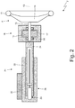
figure 2 is a schematic, partially sectional view of a transmission device of the steering system offigure 1 ; -
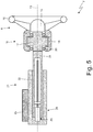
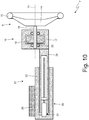
figures 3-10 are schematic, partially sectional views of corresponding variants of the transmission device shown infigure 2 ; -
figure 11 is a perspective view of a mechanical limit stop device of the transmission device shown infigures 3 ,6 and9 ; -
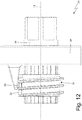
figure 12 is a side view of the limit stop mechanism offigure 11 ; -
figure 13 is a side view, with a longitudinal section, of the limit stop mechanism offigure 11 ; and -
figure 14 is a side view, with a longitudinal section, of a variant of the limit stop mechanism offigure 11 . - In
figure 1 ,number 1 indicates, as a whole, a road vehicle provided with twofront steering wheels 2 and tworear drive wheels 3, which receive the torque from a powertrain system. - The
road vehicle 1 comprises asteering system 4, which fulfils the function of controlling the steering angle, namely the angle existing between the direction of the front wheels 2 (i.e. the plane of rotation of the front wheels 2) and the longitudinal axis of theroad vehicle 1. - The
steering system 4 comprises asteering mechanism 5, which can be operated so as to change the steering angle, is arranged crosswise and consists of a central rod, which can axially slide and is mechanically connected to the fork ends of thefront wheels 2 through articulated tie rods. Furthermore, thesteering system 4 comprises asteering wheel 6, which is mounted in a rotary manner inside a passenger compartment and is electronically (virtually) connected to thesteering mechanism 5 by means of an electronic transmission device 7 (without mechanical connection) so that the rotation of thesteering wheel 6 determines an axial translation of thesteering mechanism 5 and, hence, a corresponding variation of the steering angle. In other words, there is no mechanical connection between thesteering mechanism 5 and thesteering wheel 6 and thetransmission device 7 only creates a functional (not mechanical) connection between thesteering mechanism 5 and thesteering wheel 6. - The
transmission device 7 comprises asensor 8, which detects in real time the angular position of thesteering wheel 6 and the torque applied by the driver to thesteering wheel 6; obviously, thesensor 8 is capable of determining the angular position of thesteering wheel 6 in an extremely safe manner by carrying out different independent and redundant reading operations aimed at reading the angular position of thesteering wheel 6. It should be pointed out that thesensor 8 can be directly coupled, in a mechanical manner, to thesteering wheel 6 or to any other part that is angularly integral to thesteering wheel 6. - Furthermore, the
transmission device 7 comprises an actuator device 9, which operates thesteering mechanism 5 so as to control the steering of thefront steering wheels 2 of theroad vehicle 1 and comprises anelectric motor 10 and atransmission 11, which mechanically connects theelectric motor 10 to thesteering mechanism 5. As already mentioned above, the electric motor 10 (namely, the actuator device 9) is mechanically completely independent of and separate from thesteering wheel 6 and is designed to control the steering of thefront steering wheels 2 of theroad vehicle 1 without any type of mechanical force/torque coming from thesteering wheel 6. - Finally, the
transmission device 7 comprises an electronic control unit ("ECU") 12, which is connected to theposition sensor 8 so as to receive the reading of the angular position of thesteering wheel 6 and is designed to control theelectric motor 10 of the actuator device 9 so as to adjust the steering of thefront steering wheels 2 of theroad vehicle 1 based on the angular position of thesteering wheel 6. Thecontrol unit 12 can physically consist of one single device or of different devices separated from one another and communicating with one another through the CAN network of theroad vehicle 1. - According to
figure 2 , thesteering wheel 6 is mounted so as to rotate around arotation axis 13. According to a possible embodiment (shown by way of example infigures 2-4 and8-10 ), the entire steering wheel 6 (i.e. both thecentral hub 14 and an outer ring 15) is mounted so as to rotate around therotation axis 13; according to an alternative embodiment (shown by way of example infigures 5-7 ), thecentral hub 14 of thesteering wheel 6 is fixed (i.e. it does not rotate around the rotation axis 13), whereas theouter ring 15 of thesteering wheel 6 is mounted so as to rotate around therotation axis 13. - The
transmission device 7 of thesteering system 4 comprises anelectric motor 16, which is directly connected to thesteering wheel 6 so as to apply a variable feedback torque to the steering wheel 6 (to theouter ring 15 of the steering wheel 6); in other words, the function of theelectric motor 16 is that of applying to the steering wheel 6 (to theouter ring 15 of the steering wheel 6) a variable torque that transmits to the driver torque sensations that are similar to the torque sensations of a traditional steering wheel mechanically connected to the steering wheels. In the absence of theelectric motor 16, the steering wheel 6 (theouter ring 15 of the steering wheel 6) would rotate around therotation axis 13 always with the same type of effort, thus preventing the driver from receiving any type of feedback from the steering wheel 6 (in other words, thesteering wheel 6 would behave like the steering wheel of a video game instead of like the steering wheel of the an actual vehicle). Theelectric motor 16 comprises astator 17, which does not rotate, and arotor 18, which can rotate relative to thestator 17 around the rotation axis 13 (namely, is coaxial to the steering wheel 6) and is mechanically connected to the steering wheel 6 (to theouter ring 15 of the steering wheel 6) so as to apply a variable feedback torque to thesteering wheel 6. Furthermore, theelectric motor 16 supports thesteering wheel 6, i.e. thesteering wheel 6 is mounted on theelectric motor 16; as a consequence, the steering wheel 6 (theouter ring 15 of the steering wheel 6) is rigidly integral to therotor 18 of theelectric motor 16 and is supported by therotor 18 of theelectric motor 16. - In the embodiment shown in
figures 2 and3 , in theelectric motor 16, therotor 18 is internal and, therefore, it is radially arranged on the inside of thestator 17. In this embodiment, therotor 18 of theelectric motor 16 comprises ashaft 19, which supports thesteering wheel 6; in particular, thebearings 20, which support therotor 18 and are interposed between therotor 18 and thestator 17, are preferably coupled to theshaft 19 of therotor 18. - In the alternative embodiment shown in
figures 4-8 , in theelectric motor 16, therotor 18 is external and, therefore, it is radially arranged on the outside of thestator 17. In this embodiment, therotor 18 of theelectric motor 16 generally (though, not necessarily) is without shaft. This embodiment is particularly advantageous when thecentral hub 14 of thesteering wheel 6 is fixed (i.e. does not rotate around the rotation axis 13) and the soleouter ring 15 of thesteering wheel 6 can rotate around therotation axis 13; indeed, in this embodiment, thecentral hub 14 of thesteering wheel 6 can be directly connected to thestator 17 of the electric motor 16 (i.e. thecentral hub 14 of thesteering wheel 6 can be rigidly constrained to thestator 17 of the electric motor 16), whereas theouter ring 15 of thesteering wheel 6 can be directly connected to therotor 18 of the electric motor 16 (i.e. theouter ring 15 of thesteering wheel 6 can be rigidly constrained to therotor 18 of the electric motor 16). - In all the embodiments shown in the accompanying figures, the
transmission device 7 of thesteering system 4 comprises asupport element 21, which, on one side can be rigidly fixed on the inside of the road vehicle 1 (in particular, to the dashboard of the road vehicle 1) and, on the other side, is rigidly connected to thestator 17 of theelectric motor 16 so as to support theelectric motor 16. In other words, thesupport element 21 is the mounting means through which the electric motor 16 (and, hence, thesteering wheel 6 supported by the electric motor 16) is installed and fixed on board theroad vehicle 1. - According to a preferred embodiment, the
support element 21 is telescopic so as to vary its axial size along therotation axis 13 in order to change the axial position of theelectric motor 16 and, hence, of thesteering wheel 6. In particular, thesupport element 21 comprises an outertubular body 22, which can be rigidly fixed on the inside of thevehicle 1 and is internally hollow, namely has, on the inside, achamber 23, which is open on one side (facing the electric motor 16); furthermore, thesupport element 21 comprises aninner body 24, which is rigidly connected to thestator 17 of the electric motor 16 (i.e. supports thestator 17 of the electric motor 16), is partially arranged inside the outer body 22 (i.e. in thechamber 23 of the outer body 22), and can axially slide relative to theouter body 22. It should be pointed out that theinner body 24 can only slide axially relative to theouter body 22 and, therefore, cannot make any rotation relative to theouter body 22. - In the embodiment shown in the accompanying figures, the
outer body 22 is provided with abracket 25, which is used to fix the outer body 22 (hence, the support element 21) to the dashboard of theroad vehicle 1. - The
support element 21 comprises anactuator device 26, which is arranged on the inside of the outer body 22 (i.e. is housed in thechamber 23 of the outer body 22) and is designed to axially translate theinner body 24 relative to theouter body 22. Theactuator device 26 always has the function of stopping (forbidding) the axial translation between the twobodies steering wheel 6 remains still in a predefined axial position; furthermore, theactuator device 26 can be active, i.e. have an (electric) motor, which causes an axial translation movement of theinner body 24 relative to theouter body 22, or it can be passive, i.e. need the manual intervention of the driver in order to cause an axial translation movement of theinner body 24 relative to theouter body 22. In the non-limiting embodiments shown in the accompanying figures, theactuator device 26 is active and comprises an electric motor, which is integral to theouter body 22 and causes the rotation of a worm screw, on which an abutment is screwed, which is integral to theinner body 24. - According to
figure 7 , thestator 17 of theelectric motor 16 has, at the centre, a cable-leading throughduct 27, which is coaxial to therotation axis 13; similarly, theinner body 24 of thesupport element 21 also has a cable-leading throughduct 28, which is elbow-shaped (i.e. "L"-shaped) and has an opening, which is obtained through a base wall of theinner body 24, faces and is coaxial to the cable-leadingduct 27, and another opposite opening, which is obtained through a side wall of theinner body 24. A cabling 29 (i.e. a set of electrical cables grouped together to form one single bundle) is provided, which originates from thecentral hub 14 of thesteering wheel 6 and is arranged through the cable-leadingducts steering wheel 6 to the rest of theroad vehicle 1. In this embodiment, it is possible to establish an electrical connection between thesteering wheel 6 and the rest of theroad vehicle 1 without using rotary (i.e. sliding) electrical contacts or spiral cabling (which enables a certain degree of twisting). The presence of the cable-leadingduct 27 inside thestator 17 of theelectric motor 16 is particularly advantageous when, in theelectric motor 16, therotor 18 is external (according tofigure 7 ), but it is also possible when, in theelectric motor 16, therotor 18 is internal. - In the embodiments shown in
figures 2-8 and10 , thetransmission device 7 of thesteering system 4 comprises theelectric motor 16, which applies the feedback torque to thesteering wheel 6; in the alternative embodiment shown infigure 9 , thetransmission device 7 of thesteering system 4 has noelectric motor 16 and, therefore, thesteering wheel 6 is directly connected to theinner body 24 of thesupport element 21; in particular, there is a shaft that, on one side, is rigidly connected to thesteering wheel 6 and, on the opposite side, is connected to theinner body 24 of thesupport element 21 through bearings. - In the embodiments shown in
figures 2-9 , thesupport element 21 is coaxial to theelectric motor 16 and to thesteering wheel 6; in the alternative embodiment shown infigure 10 , thesupport element 21 is not aligned with theelectric motor 16 and with thesteering wheel 6 and is mounted lower than theelectric motor 16 and thesteering wheel 6; the lack of alignment between thesupport element 21 and theelectric motor 16 as well as thesteering wheel 6 increases the space available in the part of dashboard above the support element 21 (since thebracket 25 can be placed lower), thus creating a larger space for information devices (control panel, screens) or other devices to be installed in the upper part of the dashboard in front of the driver. - In the embodiments shown in
figures 3 ,6 and9 , thetransmission device 7 of thesteering system 4 comprises a mechanicallimit stop device 30, which is coupled to thesteering wheel 6 and limits, in both directions, the maximum angular width of the rotation of thesteering wheel 6 around therotation axis 13, so that thesteering wheel 6 can make, on the whole, a rotation around therotation axis 13 that is greater than 360°. It should be pointed out that the fact that thesteering wheel 6 is allowed to rotate, on the whole, over more than 360° ensures (when desired) a high steering "reduction", namely in order to avoid (when desired) a too direct steering (which is ideal when driving on a race track, but is not suitable for everyday driving in traffic). In the absence of the mechanicallimit stop device 30, it would be necessary to create "virtual" limit stops using theelectric motor 16 to generate a very high braking torque, which simulates the presence of a mechanical limits stop; however, this solution, despite being very elegant, requires an oversized electric motor 16 (in order to allow theelectric motor 16 to generate a braking torque that is high enough to stop the rotation of the steering wheel 6) and, hence, leads to an increase in size, mass and costs. - According to
figures 11-14 , thelimit stop device 30 comprises agroove 31, which is wound in a spiral around therotation axis 13 over more than 360° and has, at the two opposite ends, twoabutments 32, which define respective stop strikers; in other words, thegroove 31 extends in a spiral around therotation axis 13 over more than 360° from anabutment 32 to theopposite abutment 32. By way of example, thegroove 31 could extend around therotation axis 13 over approximately 720° (i.e. two complete rotations of the steering wheel 6) or over approximately 1080° (i.e. three complete rotations of the steering wheel 6). Furthermore, thelimit stop device 30 comprises apin 33, which is arranged inside thegroove 31 so as to engage and follow thegroove 31 from anabutment 32 up to theopposite abutment 32; in other words, thepin 33 is inside thegroove 31 and is forced to remain inside thegroove 31, thus covering the entire extension of thegroove 31 from anabutment 32 to theopposite abutment 32. - Furthermore, one between the
groove 31 and thepin 33 is angularly integral to the steering wheel 6 (hence, rotates in an angularly integral manner with the steering wheel 6), whereas the other one between thegroove 31 and thepin 33 is angularly integral to a part that does not rotate together with the steering wheel 6 (in particular, is angularly integral to theinner body 24 of the support element 21). In other words, according to a possible embodiment, thegroove 31 is angularly integral to thesteering wheel 6, whereas thepin 33 is angularly integral to a part that does not rotate with the steering wheel 6 (i.e. is angularly integral to theinner body 24 of the support element 21); alternatively, thepin 33 is angularly integral to thesteering wheel 6, whereas thegroove 31 is angularly integral to a part that does not rotate with the steering wheel 6 (i.e. is angularly integral to theinner body 24 of the support element 21). - Finally, one between the
groove 31 and thepin 33 can axially slide relative to thesteering wheel 6. In other words, thegroove 31 can axially slide relative to thesteering wheel 6 or thepin 33 can axially slide relative to thesteering wheel 6. - In the embodiment shown in
figures 11 ,12 and13 , thegroove 31 is angularly integral to the steering wheel 6 (in particular, to ashaft 34 coaxial to therotation axis 13 which rigidly supports at least theouter ring 15 of the steering wheel 6) and can also axially slide relative to the steering wheel 6 (in particular, relative to the shaft 34); as a consequence, thepin 33 is rigidly connected to a part that does not rotate with the steering wheel 6 (i.e. is angularly integral to theinner body 24 of the support element 21). In this embodiment, thegroove 31 is coupled to the steering wheel 6 (in particular, to the shaft 34) through a splined coupling, which constrains in an angular manner, enabling, at the same time, an axial sliding. It should be pointed out that thegroove 31 can be mounted on any part that is angularly integral to the steering wheel 6 (i.e. that rotates around therotation axis 13 together with the steering wheel 6), for example theshaft 34 coaxial to therotation axis 13 which rigidly supports at least theouter ring 15 of thesteering wheel 6, therotor 18 of theelectric motor 16 or thesteering wheel 6 itself. - In the embodiment shown in
figure 14 , thegroove 31 is angularly integral to the steering wheel 6 (in particular, to ashaft 34 coaxial to therotation axis 13 which rigidly supports at least theouter ring 15 of the steering wheel 6) and is also rigidly constrained to the steering wheel 6 (in particular, to the shaft 34); as a consequence, thepin 33 is angularly integral and can axially slide relative to a part that does not rotate with the steering wheel 6 (i.e. is angularly integral and can axially slide relative to theinner body 24 of the support element 21). In other words, thepin 33 can axially slide, but cannot rotate relative to a part that does not rotate together with the steering wheel 6 (i.e. relative to theinner body 24 of the support element 21). - The embodiments described herein can be combined with one another, without for this reason going beyond the scope of protection of the invention.
- The
steering system 4 described above has numerous advantages. - First of all, the
steering system 4 described above is particularly compact, effective and efficient, since the total number of components of thetransmission device 7 is reduced to a minimum. In particular, thesteering wheel 6 is directly supported by theelectric motor 16, which, hence, applies the feedback torque to thesteering wheel 6 without intermediate elements. Furthermore, thesupport element 21 is extremely simple, functional and compact, as it has a tubular shape housing, on the inside, theactuator device 26, which regulates the axial movements of thesteering wheel 6. - Moreover, the
support element 21 allows thesteering wheel 6 to cover a much wider axial stroke, which can get up to 250 mm, without particular constructive complications (also thanks to the absence of a connection shaft towards the steering mechanism 5). -
- 1
- road vehicle
- 2
- front wheels
- 3
- rear wheels
- 4
- steering system
- 5
- steering mechanism
- 6
- steering wheel
- 7
- transmission device
- 8
- sensor
- 9
- actuator device
- 10
- electric motor
- 11
- transmission
- 12
- control unit
- 13
- rotation axis
- 14
- central hub
- 15
- outer ring
- 16
- electric motor
- 17
- stator
- 18
- rotor
- 19
- shaft
- 20
- bearings
- 21
- support element
- 22
- outer body
- 23
- chamber
- 24
- inner body
- 25
- bracket
- 26
- actuator device
- 27
- cable-leading duct
- 28
- cable-leading duct
- 29
- cabling
- 30
- limit stop device
- 31
- groove
- 32
- abutment
- 33
- pin
- 34
- shaft
Claims (13)
- A steering system (4) for a road vehicle (1); the steering system (4) comprises:a steering wheel (6) provided with an outer ring (15), which is mounted so as to rotate around a rotation axis (13) and has no connection to steering wheels (2);a support element (21), which, on one side, can be rigidly fixed on the inside of the vehicle (1) and, on the other side, is connected to the steering wheel (6) so as to support the steering wheel (6); anda position sensor (8), which is designed to detect the angular position of the outer ring (15) of the steering wheel (6) around the rotation axis (13);wherein the support element (21) is telescopic so as to vary its axial size along the rotation axis (13) in order to change the axial position of the steering wheel (6) ;wherein the support element (21) comprises: an outer body (22), which can be rigidly fixed on the inside of the vehicle (1) and is internally hollow; an inner body (24), which is connected to the steering wheel (6), is partially arranged on the inside of the outer body (22), and can axially slide relative to the outer body (22); and an actuator device (26), which is designed to axially translate the inner body (24) relative to the outer body (22) ;the steering system (4) is characterized in that the actuator device (26) is arranged on the inside of the outer body (22).
- The steering system (4) according to claim 1, wherein the outer body (22) is tubular and has, on the inside, a chamber (23), which is open on one side, partially houses the inner body (24) in an axially sliding manner, and houses the actuator device (26).
- The steering system (4) according to claim 1 or 2, wherein the actuator device (26) is designed to stop the axial translation between the outer body (22) and the inner body (24) so as to make sure that, in use, the steering wheel (6) remains still in a predefined axial position.
- The steering system (4) according to claim 1, 2 or 3, wherein the actuator device (26) is active and comprises a first electric motor, which causes an axial translation movement of the inner body (24) relative to the outer body (22) .
- The steering system (4) according to claim 4, wherein the actuator device (26) comprises:the first electric motor, which is integral to the outer body (22);a worm screw, which is caused to rotate by the first electric motor; andan abutment, which is screwed in the worm screw and is integral to the inner body (24).
- The steering system (4) according to one of the claims from 1 to 5, wherein the support element (21) is not aligned with the steering wheel (6) and is arranged lower than the steering wheel (6).
- The steering system (4) according to one of the claims from 1 to 6 and comprising a second electric motor (16), which applies a variable feedback torque to the outer ring (15) of the steering wheel (6), is interposed between the support element (21) and the steering wheel (6) so as to support the steering wheel (6), and comprises a stator (17), which is rigidly connected to the support element (21), and a rotor (18), which is rigidly connected at least to the outer ring (15) of the steering wheel (6).
- The steering system (4) according to one of the claims from 1 to 7 and comprising a third electric motor (10), which is mechanically completely independent of and separate from the steering wheel (6) and is designed to control the steering of the steering wheels (2) of the vehicle (1).
- The steering system (4) according to claim 8 and comprising a control unit (12), which is connected to the position sensor (8) so as to receive the reading of the angular position of the steering wheel (6) and is designed to control the third electric motor (10) so as to adjust the steering of the steering wheels (2) of the vehicle (1) based on the angular position of the steering wheel (6).
- The steering system (4) according to one of the claims from 1 to 9 and comprising a mechanical limit stop device (30), which is coupled to the outer ring (15) of the steering wheel (6) and limits, in both directions, the maximum angular width of the rotation of the steering wheel (6) around the rotation axis (13), so that the steering wheel (6) can make, on the whole, a rotation around the rotation axis (13) that is greater than 360°.
- The steering system (4) according to claim 10, wherein:the limit stop device (30) comprises a groove (31), which is wound in a spiral shape around the rotation axis (13) over more than 360° and has, at the two opposite ends, two abutments (32), which define respective stop strikers;the limit stop device (30) comprises a pin (33), which is arranged on the inside of the groove (31) so as to engage and follow the groove (31) from an abutment (32) to the opposite abutment (32);one between the groove (31) and the pin (33) is angularly integral to the outer ring (15) of the steering wheel (6), whereas the other one between the groove (31) and the pin (33) is angularly integral to a part that does not rotate together with the outer ring (15) of the steering wheel (6); andone between the groove (31) and the pin (33) can axially slide relative to the outer ring (15) of the steering wheel (6).
- The steering system (4) according to claim 11, wherein:the groove (31) is angularly integral to the outer ring (15) of the steering wheel (6) and can axially slide relative to the outer ring (15) of the steering wheel (6); andthe pin (33) is rigidly connected to a part that does not rotate together with the steering wheel (6).
- The steering system (4) according to claim 12, wherein the groove (31) is coupled to the steering wheel (6) through a splined coupling.
Applications Claiming Priority (1)
| Application Number | Priority Date | Filing Date | Title |
|---|---|---|---|
| IT102017000121876A IT201700121876A1 (en) | 2017-10-26 | 2017-10-26 | "STEER BY WIRE" ROAD VEHICLE SYSTEM AND PROVIDED WITH A TELESCOPIC SUPPORTING ELEMENT FOR THE STEERING WHEEL " |
Publications (2)
| Publication Number | Publication Date |
|---|---|
| EP3476692A1 true EP3476692A1 (en) | 2019-05-01 |
| EP3476692B1 EP3476692B1 (en) | 2020-12-02 |
Family
ID=61581435
Family Applications (1)
| Application Number | Title | Priority Date | Filing Date |
|---|---|---|---|
| EP18202958.7A Active EP3476692B1 (en) | 2017-10-26 | 2018-10-26 | "steer by wire" road vehicle steering system provided with a telescopic support element for the steering wheel |
Country Status (3)
| Country | Link |
|---|---|
| US (1) | US11027770B2 (en) |
| EP (1) | EP3476692B1 (en) |
| IT (1) | IT201700121876A1 (en) |
Cited By (21)
| Publication number | Priority date | Publication date | Assignee | Title |
|---|---|---|---|---|
| FR3086254A1 (en) * | 2018-09-26 | 2020-03-27 | Psa Automobiles Sa | STEERING CONTROL EQUIPMENT FOR MOTOR VEHICLE |
| WO2020211987A1 (en) * | 2019-04-17 | 2020-10-22 | Volkswagen Aktiengesellschaft | Steer-by-wire steering system for a motor vehicle comprising a concentric drive unit |
| WO2021032530A1 (en) * | 2019-08-20 | 2021-02-25 | Thyssenkrupp Presta Ag | Adjustable steering column for a motor vehicle with rotation limitation |
| WO2021032526A1 (en) * | 2019-08-20 | 2021-02-25 | Thyssenkrupp Presta Ag | Steering column for a motor vehicle with rotation limitation |
| CN112896286A (en) * | 2019-12-04 | 2021-06-04 | 现代自动车株式会社 | Apparatus for receiving steering wheel and control method thereof |
| EP3960584A1 (en) * | 2020-08-28 | 2022-03-02 | Lotus Tech Innovation Centre GmbH | Steer-by-wire steering system having an off-axis steering system support column provided with a steering wheel rotation limiting device |
| EP3960583A1 (en) * | 2020-08-28 | 2022-03-02 | Lotus Tech Innovation Centre GmbH | Steer-by-wire steering system having an off-axis steering system support column |
| EP3960582A1 (en) * | 2020-08-28 | 2022-03-02 | Lotus Tech Innovation Centre GmbH | Steer-by-wire steering system comprising an outer rotor torque feedback device |
| EP3960585A1 (en) * | 2020-08-28 | 2022-03-02 | Lotus Tech Innovation Centre GmbH | Steer-by-wire steering system comprising a steering wheel rotation limiting device |
| WO2023284949A1 (en) * | 2021-07-13 | 2023-01-19 | Lotus Tech Innovation Centre Gmbh | Retractable steering wheel arrangement for a steer-by-wire steering system |
| WO2023284948A1 (en) * | 2021-07-13 | 2023-01-19 | Lotus Tech Innovation Centre Gmbh | Retractable steering wheel arrangement with non-planar steering wheel rim |
| WO2024088473A1 (en) | 2022-10-28 | 2024-05-02 | Schaeffler Technologies AG & Co. KG | Adjusting unit of a steering column |
| WO2024088456A1 (en) | 2022-10-28 | 2024-05-02 | Schaeffler Technologies AG & Co. KG | Adjusting unit of a steering column |
| DE102022133669A1 (en) | 2022-10-28 | 2024-05-08 | Schaeffler Technologies AG & Co. KG | Adjustment unit of a steering column |
| US11999407B1 (en) | 2023-02-21 | 2024-06-04 | Ford Global Technologies, Llc | Translating steering column with reduced packaging space |
| DE102023100870A1 (en) * | 2023-01-16 | 2024-07-18 | Schaeffler Technologies AG & Co. KG | Steering system for a motor vehicle |
| DE102023112782A1 (en) | 2023-05-15 | 2024-11-21 | Schaeffler Technologies AG & Co. KG | adjustment unit of a steering column |
| DE102023115819A1 (en) | 2023-06-16 | 2024-12-19 | Schaeffler Technologies AG & Co. KG | adjustment unit of a steering column |
| WO2025009308A1 (en) * | 2023-07-06 | 2025-01-09 | ニデック株式会社 | Motor, actuator, and steering device |
| WO2025009309A1 (en) * | 2023-07-06 | 2025-01-09 | ニデック株式会社 | Motor, actuator, and steering device |
| WO2025009307A1 (en) * | 2023-07-06 | 2025-01-09 | ニデック株式会社 | Actuator and steering device |
Families Citing this family (11)
| Publication number | Priority date | Publication date | Assignee | Title |
|---|---|---|---|---|
| DE102015224602B4 (en) * | 2015-12-08 | 2023-05-04 | Thyssenkrupp Ag | Steering column for a steer-by-wire steering device |
| JP6926835B2 (en) * | 2017-08-30 | 2021-08-25 | いすゞ自動車株式会社 | Steering device |
| CN115298079A (en) * | 2020-03-17 | 2022-11-04 | 日立安斯泰莫株式会社 | Steering control device |
| CN114684247B (en) * | 2020-12-30 | 2023-09-05 | 比亚迪股份有限公司 | Corner limiting mechanism, vehicle steering system with same and vehicle |
| DE102021202481B3 (en) * | 2021-03-15 | 2021-12-16 | Thyssenkrupp Ag | Method and electrically adjustable steering column for adjusting an actuating unit of a steering column |
| KR102906017B1 (en) * | 2021-08-02 | 2025-12-30 | 에이치엘만도 주식회사 | Steer-By-Wire Type Steering Apparatus |
| DE102021211576A1 (en) * | 2021-10-14 | 2023-04-20 | Robert Bosch Gesellschaft mit beschränkter Haftung | Steering column for a steer-by-wire steering system |
| DE102023105802A1 (en) | 2023-03-09 | 2024-09-12 | Schaeffler Technologies AG & Co. KG | Steering device and method for producing a stator |
| DE102023108159B4 (en) | 2023-03-30 | 2025-08-07 | Schaeffler Technologies AG & Co. KG | Steering device |
| DE102023113234A1 (en) | 2023-05-22 | 2024-11-28 | Schaeffler Technologies AG & Co. KG | Control unit, method for functional testing of a magneto-rheological brake, computer program product and steer-by-wire system |
| DE102023113235A1 (en) | 2023-05-22 | 2024-11-28 | Schaeffler Technologies AG & Co. KG | Control unit, method for functional testing of a magneto-rheological brake, computer program product and steer-by-wire system |
Citations (4)
| Publication number | Priority date | Publication date | Assignee | Title |
|---|---|---|---|---|
| US20160068182A1 (en) | 2013-05-22 | 2016-03-10 | Deere & Company | Electrohydraulic steer-by-wire steering system |
| US20170158222A1 (en) | 2015-12-03 | 2017-06-08 | Steering Solutions Ip Holding Corporation | Torque feedback system for a steer-by-wire vehicle, vehicle having steering column, and method of providing feedback in vehicle |
| DE102015224602A1 (en) | 2015-12-08 | 2017-06-08 | Thyssenkrupp Ag | Steering column for a steer-by-wire steering device |
| WO2017115411A1 (en) | 2015-12-28 | 2017-07-06 | 三菱電機株式会社 | Steer-by-wire electrical power steering device, and control method therefor |
Family Cites Families (9)
| Publication number | Priority date | Publication date | Assignee | Title |
|---|---|---|---|---|
| JPH03157266A (en) * | 1989-11-14 | 1991-07-05 | Nippon Seiko Kk | Motor-driven extendable steering column device |
| US6896089B2 (en) * | 2002-02-05 | 2005-05-24 | Ford Global Technologies, Llc | Steer-by-wire steering system with rotation limiter |
| JP5804198B2 (en) * | 2012-05-16 | 2015-11-04 | 日産自動車株式会社 | Vehicle steering control apparatus and steering control method |
| CN104995077B (en) * | 2013-01-11 | 2017-03-08 | 日产自动车株式会社 | Runner control device |
| US10427705B2 (en) * | 2017-06-30 | 2019-10-01 | GM Global Technology Operations LLC | Steering wheel with fixed eccentric center hub |
| DE102017007841A1 (en) * | 2017-08-17 | 2019-02-21 | Leopold Kostal Gmbh & Co. Kg | motor vehicle |
| DE102017120669B4 (en) * | 2017-09-07 | 2025-03-20 | Zf Automotive Germany Gmbh | Steering column assembly for a motor vehicle and steering system |
| DE102017218894A1 (en) * | 2017-10-23 | 2019-04-25 | Thyssenkrupp Ag | Steering column for a motor vehicle |
| CN108909820A (en) * | 2018-09-05 | 2018-11-30 | 中信戴卡股份有限公司 | A kind of automobile steering disc assembly and automobile |
-
2017
- 2017-10-26 IT IT102017000121876A patent/IT201700121876A1/en unknown
-
2018
- 2018-10-26 EP EP18202958.7A patent/EP3476692B1/en active Active
- 2018-10-26 US US16/171,443 patent/US11027770B2/en active Active
Patent Citations (5)
| Publication number | Priority date | Publication date | Assignee | Title |
|---|---|---|---|---|
| US20160068182A1 (en) | 2013-05-22 | 2016-03-10 | Deere & Company | Electrohydraulic steer-by-wire steering system |
| US20170158222A1 (en) | 2015-12-03 | 2017-06-08 | Steering Solutions Ip Holding Corporation | Torque feedback system for a steer-by-wire vehicle, vehicle having steering column, and method of providing feedback in vehicle |
| DE102015224602A1 (en) | 2015-12-08 | 2017-06-08 | Thyssenkrupp Ag | Steering column for a steer-by-wire steering device |
| WO2017097662A1 (en) | 2015-12-08 | 2017-06-15 | Thyssenkrupp Presta Ag | Steering column for a steer-by-wire steering device |
| WO2017115411A1 (en) | 2015-12-28 | 2017-07-06 | 三菱電機株式会社 | Steer-by-wire electrical power steering device, and control method therefor |
Cited By (43)
| Publication number | Priority date | Publication date | Assignee | Title |
|---|---|---|---|---|
| WO2020065159A1 (en) * | 2018-09-26 | 2020-04-02 | Psa Automobiles Sa | Steering control equipment for a motor vehicle |
| FR3086254A1 (en) * | 2018-09-26 | 2020-03-27 | Psa Automobiles Sa | STEERING CONTROL EQUIPMENT FOR MOTOR VEHICLE |
| WO2020211987A1 (en) * | 2019-04-17 | 2020-10-22 | Volkswagen Aktiengesellschaft | Steer-by-wire steering system for a motor vehicle comprising a concentric drive unit |
| CN114269629A (en) * | 2019-08-20 | 2022-04-01 | 蒂森克虏伯普利斯坦股份公司 | Steering column with rotation limitation for a motor vehicle |
| WO2021032530A1 (en) * | 2019-08-20 | 2021-02-25 | Thyssenkrupp Presta Ag | Adjustable steering column for a motor vehicle with rotation limitation |
| WO2021032526A1 (en) * | 2019-08-20 | 2021-02-25 | Thyssenkrupp Presta Ag | Steering column for a motor vehicle with rotation limitation |
| US12168482B2 (en) | 2019-08-20 | 2024-12-17 | Thyssenkrupp Presta Ag | Steering column for a motor vehicle with rotation limitation |
| CN114269629B (en) * | 2019-08-20 | 2024-06-11 | 蒂森克虏伯普利斯坦股份公司 | Steering column for a motor vehicle with rotation limitation |
| CN114269628B (en) * | 2019-08-20 | 2024-04-12 | 蒂森克虏伯普利斯坦股份公司 | Steering column for a motor vehicle with a rotation limiting device |
| CN114269628A (en) * | 2019-08-20 | 2022-04-01 | 蒂森克虏伯普利斯坦股份公司 | Steering column for a motor vehicle with a rotation limiting device |
| CN112896286A (en) * | 2019-12-04 | 2021-06-04 | 现代自动车株式会社 | Apparatus for receiving steering wheel and control method thereof |
| CN115996872A (en) * | 2020-08-28 | 2023-04-21 | 路特斯技术创新中心有限公司 | Steer-by-wire steering systems including steering wheel rotation limiting devices |
| CN115996872B (en) * | 2020-08-28 | 2025-09-16 | 杭州擎威科技有限公司 | Steer-by-wire steering system including steering wheel rotation limiting device |
| WO2022043532A1 (en) * | 2020-08-28 | 2022-03-03 | Lotus Tech Innovation Centre Gmbh | Steer-by-wire steering system comprising a steering wheel rotation limiting device |
| WO2022043534A1 (en) * | 2020-08-28 | 2022-03-03 | Lotus Tech Innovation Centre Gmbh | Steer-by-wire steering system having an off-axis steering system support column |
| WO2022043535A1 (en) * | 2020-08-28 | 2022-03-03 | Lotus Tech Innovation Centre Gmbh | Steer-by-wire steering system comprising an outer rotor torque feedback device |
| EP3960583A1 (en) * | 2020-08-28 | 2022-03-02 | Lotus Tech Innovation Centre GmbH | Steer-by-wire steering system having an off-axis steering system support column |
| US12233962B2 (en) | 2020-08-28 | 2025-02-25 | Hangzhou Kingway Technology Co., Ltd. | Steer-by-wire steering system comprising a steering wheel rotation limiting device |
| CN115968345A (en) * | 2020-08-28 | 2023-04-14 | 路特斯技术创新中心有限公司 | Steer-by-wire steering system with off-axis steering system support column |
| CN115989169A (en) * | 2020-08-28 | 2023-04-18 | 路特斯技术创新中心有限公司 | Steer-by-wire steering system including outer rotor torque feedback device |
| EP3960585A1 (en) * | 2020-08-28 | 2022-03-02 | Lotus Tech Innovation Centre GmbH | Steer-by-wire steering system comprising a steering wheel rotation limiting device |
| EP4275992A3 (en) * | 2020-08-28 | 2024-02-21 | Lotus Tech Innovation Centre GmbH | Steer-by-wire steering system having an off-axis steering system support column |
| EP3960582A1 (en) * | 2020-08-28 | 2022-03-02 | Lotus Tech Innovation Centre GmbH | Steer-by-wire steering system comprising an outer rotor torque feedback device |
| CN115968345B (en) * | 2020-08-28 | 2025-10-10 | 杭州擎威科技有限公司 | Steer-by-wire steering with offset steering column |
| EP3960584A1 (en) * | 2020-08-28 | 2022-03-02 | Lotus Tech Innovation Centre GmbH | Steer-by-wire steering system having an off-axis steering system support column provided with a steering wheel rotation limiting device |
| WO2022043533A1 (en) * | 2020-08-28 | 2022-03-03 | Lotus Tech Innovation Centre Gmbh | Steer-by-wire steering system having an off-axis steering system support column provided with a steering wheel rotation limiting device |
| US12351232B2 (en) | 2021-07-13 | 2025-07-08 | Hangzhou Kingway Technology Co., Ltd. | Retractable steering wheel arrangement with non-planar steering wheel rim |
| WO2023284948A1 (en) * | 2021-07-13 | 2023-01-19 | Lotus Tech Innovation Centre Gmbh | Retractable steering wheel arrangement with non-planar steering wheel rim |
| WO2023284949A1 (en) * | 2021-07-13 | 2023-01-19 | Lotus Tech Innovation Centre Gmbh | Retractable steering wheel arrangement for a steer-by-wire steering system |
| DE102022133669A1 (en) | 2022-10-28 | 2024-05-08 | Schaeffler Technologies AG & Co. KG | Adjustment unit of a steering column |
| WO2024088473A1 (en) | 2022-10-28 | 2024-05-02 | Schaeffler Technologies AG & Co. KG | Adjusting unit of a steering column |
| WO2024088456A1 (en) | 2022-10-28 | 2024-05-02 | Schaeffler Technologies AG & Co. KG | Adjusting unit of a steering column |
| DE102023110003A1 (en) | 2022-10-28 | 2024-05-08 | Schaeffler Technologies AG & Co. KG | Adjustment unit of a steering column |
| DE102023110003B4 (en) * | 2022-10-28 | 2025-04-30 | Schaeffler Technologies AG & Co. KG | Adjustment unit of a steering column |
| DE102023100870A1 (en) * | 2023-01-16 | 2024-07-18 | Schaeffler Technologies AG & Co. KG | Steering system for a motor vehicle |
| DE102023100870B4 (en) | 2023-01-16 | 2024-08-08 | Schaeffler Technologies AG & Co. KG | Steering system for a motor vehicle |
| US11999407B1 (en) | 2023-02-21 | 2024-06-04 | Ford Global Technologies, Llc | Translating steering column with reduced packaging space |
| DE102023112782A1 (en) | 2023-05-15 | 2024-11-21 | Schaeffler Technologies AG & Co. KG | adjustment unit of a steering column |
| DE102023115819A1 (en) | 2023-06-16 | 2024-12-19 | Schaeffler Technologies AG & Co. KG | adjustment unit of a steering column |
| DE102023115819B4 (en) * | 2023-06-16 | 2024-12-24 | Schaeffler Technologies AG & Co. KG | adjustment unit of a steering column |
| WO2025009307A1 (en) * | 2023-07-06 | 2025-01-09 | ニデック株式会社 | Actuator and steering device |
| WO2025009309A1 (en) * | 2023-07-06 | 2025-01-09 | ニデック株式会社 | Motor, actuator, and steering device |
| WO2025009308A1 (en) * | 2023-07-06 | 2025-01-09 | ニデック株式会社 | Motor, actuator, and steering device |
Also Published As
| Publication number | Publication date |
|---|---|
| US20190135332A1 (en) | 2019-05-09 |
| IT201700121876A1 (en) | 2019-04-26 |
| US11027770B2 (en) | 2021-06-08 |
| EP3476692B1 (en) | 2020-12-02 |
Similar Documents
| Publication | Publication Date | Title |
|---|---|---|
| EP3476692B1 (en) | "steer by wire" road vehicle steering system provided with a telescopic support element for the steering wheel | |
| EP3476693B1 (en) | "steer by wire" road vehicle steering system provided with a mechanical limit stop device for the steering wheel | |
| US20200346682A1 (en) | Steering column for a motor vehicle | |
| CN109153406B (en) | Steer-by-wire steering system and method for controlling a steer-by-wire system | |
| US6688645B2 (en) | Turn-limited column assembly | |
| US6820713B2 (en) | Hand wheel actuator with steering-feel enhancement | |
| JP2009501107A (en) | Electric steering for vehicles | |
| KR101459429B1 (en) | Turn stopper for steer-by-wire system | |
| CN112703145A (en) | Steering column and steer-by-wire system | |
| US8893846B2 (en) | Power assisted steering assembly | |
| CN112550426B (en) | Steering column assembly for vehicle | |
| US8777265B2 (en) | Steering device for motor vehicles | |
| CN117916140A (en) | Steering actuator for steer-by-wire steering system | |
| KR102174602B1 (en) | Steering apparatus for vehicle | |
| US7594563B2 (en) | Rotary damper resistance for steering system | |
| JP2007522019A (en) | Vehicle steering system | |
| CN101970278B (en) | Servo valve for a hydraulic power-assisted steering system | |
| JP7668421B2 (en) | Steering column for steer-by-wire steering system | |
| EP1301386B1 (en) | Electric steering system with mechanical back-up device | |
| JP4581506B2 (en) | Vehicle steering system | |
| CN112776879A (en) | Hand force actuator system for drive-by-wire system of vehicle | |
| KR102858583B1 (en) | Electric Power Steering Apparatus for Vehicle | |
| US11914414B2 (en) | Control device for operating at least one vehicle actuator | |
| US20250128759A1 (en) | Steering gear for a steer-by-wire steering device and steer-by-wire steering device with such a steering gear | |
| US20070251756A1 (en) | Automotive Steering System |
Legal Events
| Date | Code | Title | Description |
|---|---|---|---|
| PUAI | Public reference made under article 153(3) epc to a published international application that has entered the european phase |
Free format text: ORIGINAL CODE: 0009012 |
|
| STAA | Information on the status of an ep patent application or granted ep patent |
Free format text: STATUS: THE APPLICATION HAS BEEN PUBLISHED |
|
| AK | Designated contracting states |
Kind code of ref document: A1 Designated state(s): AL AT BE BG CH CY CZ DE DK EE ES FI FR GB GR HR HU IE IS IT LI LT LU LV MC MK MT NL NO PL PT RO RS SE SI SK SM TR |
|
| AX | Request for extension of the european patent |
Extension state: BA ME |
|
| STAA | Information on the status of an ep patent application or granted ep patent |
Free format text: STATUS: REQUEST FOR EXAMINATION WAS MADE |
|
| 17P | Request for examination filed |
Effective date: 20191030 |
|
| STAA | Information on the status of an ep patent application or granted ep patent |
Free format text: STATUS: EXAMINATION IS IN PROGRESS |
|
| 17Q | First examination report despatched |
Effective date: 20200219 |
|
| GRAP | Despatch of communication of intention to grant a patent |
Free format text: ORIGINAL CODE: EPIDOSNIGR1 |
|
| STAA | Information on the status of an ep patent application or granted ep patent |
Free format text: STATUS: GRANT OF PATENT IS INTENDED |
|
| INTG | Intention to grant announced |
Effective date: 20200623 |
|
| GRAS | Grant fee paid |
Free format text: ORIGINAL CODE: EPIDOSNIGR3 |
|
| GRAA | (expected) grant |
Free format text: ORIGINAL CODE: 0009210 |
|
| STAA | Information on the status of an ep patent application or granted ep patent |
Free format text: STATUS: THE PATENT HAS BEEN GRANTED |
|
| AK | Designated contracting states |
Kind code of ref document: B1 Designated state(s): AL AT BE BG CH CY CZ DE DK EE ES FI FR GB GR HR HU IE IS IT LI LT LU LV MC MK MT NL NO PL PT RO RS SE SI SK SM TR |
|
| REG | Reference to a national code |
Ref country code: GB Ref legal event code: FG4D |
|
| REG | Reference to a national code |
Ref country code: AT Ref legal event code: REF Ref document number: 1340625 Country of ref document: AT Kind code of ref document: T Effective date: 20201215 Ref country code: CH Ref legal event code: EP |
|
| REG | Reference to a national code |
Ref country code: IE Ref legal event code: FG4D |
|
| REG | Reference to a national code |
Ref country code: DE Ref legal event code: R096 Ref document number: 602018010375 Country of ref document: DE |
|
| PG25 | Lapsed in a contracting state [announced via postgrant information from national office to epo] |
Ref country code: RS Free format text: LAPSE BECAUSE OF FAILURE TO SUBMIT A TRANSLATION OF THE DESCRIPTION OR TO PAY THE FEE WITHIN THE PRESCRIBED TIME-LIMIT Effective date: 20201202 Ref country code: FI Free format text: LAPSE BECAUSE OF FAILURE TO SUBMIT A TRANSLATION OF THE DESCRIPTION OR TO PAY THE FEE WITHIN THE PRESCRIBED TIME-LIMIT Effective date: 20201202 Ref country code: NO Free format text: LAPSE BECAUSE OF FAILURE TO SUBMIT A TRANSLATION OF THE DESCRIPTION OR TO PAY THE FEE WITHIN THE PRESCRIBED TIME-LIMIT Effective date: 20210302 Ref country code: GR Free format text: LAPSE BECAUSE OF FAILURE TO SUBMIT A TRANSLATION OF THE DESCRIPTION OR TO PAY THE FEE WITHIN THE PRESCRIBED TIME-LIMIT Effective date: 20210303 |
|
| REG | Reference to a national code |
Ref country code: NL Ref legal event code: MP Effective date: 20201202 |
|
| REG | Reference to a national code |
Ref country code: AT Ref legal event code: MK05 Ref document number: 1340625 Country of ref document: AT Kind code of ref document: T Effective date: 20201202 |
|
| PG25 | Lapsed in a contracting state [announced via postgrant information from national office to epo] |
Ref country code: BG Free format text: LAPSE BECAUSE OF FAILURE TO SUBMIT A TRANSLATION OF THE DESCRIPTION OR TO PAY THE FEE WITHIN THE PRESCRIBED TIME-LIMIT Effective date: 20210302 Ref country code: LV Free format text: LAPSE BECAUSE OF FAILURE TO SUBMIT A TRANSLATION OF THE DESCRIPTION OR TO PAY THE FEE WITHIN THE PRESCRIBED TIME-LIMIT Effective date: 20201202 Ref country code: PL Free format text: LAPSE BECAUSE OF FAILURE TO SUBMIT A TRANSLATION OF THE DESCRIPTION OR TO PAY THE FEE WITHIN THE PRESCRIBED TIME-LIMIT Effective date: 20201202 Ref country code: SE Free format text: LAPSE BECAUSE OF FAILURE TO SUBMIT A TRANSLATION OF THE DESCRIPTION OR TO PAY THE FEE WITHIN THE PRESCRIBED TIME-LIMIT Effective date: 20201202 |
|
| PG25 | Lapsed in a contracting state [announced via postgrant information from national office to epo] |
Ref country code: HR Free format text: LAPSE BECAUSE OF FAILURE TO SUBMIT A TRANSLATION OF THE DESCRIPTION OR TO PAY THE FEE WITHIN THE PRESCRIBED TIME-LIMIT Effective date: 20201202 Ref country code: NL Free format text: LAPSE BECAUSE OF FAILURE TO SUBMIT A TRANSLATION OF THE DESCRIPTION OR TO PAY THE FEE WITHIN THE PRESCRIBED TIME-LIMIT Effective date: 20201202 |
|
| REG | Reference to a national code |
Ref country code: LT Ref legal event code: MG9D |
|
| PG25 | Lapsed in a contracting state [announced via postgrant information from national office to epo] |
Ref country code: SK Free format text: LAPSE BECAUSE OF FAILURE TO SUBMIT A TRANSLATION OF THE DESCRIPTION OR TO PAY THE FEE WITHIN THE PRESCRIBED TIME-LIMIT Effective date: 20201202 Ref country code: SM Free format text: LAPSE BECAUSE OF FAILURE TO SUBMIT A TRANSLATION OF THE DESCRIPTION OR TO PAY THE FEE WITHIN THE PRESCRIBED TIME-LIMIT Effective date: 20201202 Ref country code: EE Free format text: LAPSE BECAUSE OF FAILURE TO SUBMIT A TRANSLATION OF THE DESCRIPTION OR TO PAY THE FEE WITHIN THE PRESCRIBED TIME-LIMIT Effective date: 20201202 Ref country code: CZ Free format text: LAPSE BECAUSE OF FAILURE TO SUBMIT A TRANSLATION OF THE DESCRIPTION OR TO PAY THE FEE WITHIN THE PRESCRIBED TIME-LIMIT Effective date: 20201202 Ref country code: PT Free format text: LAPSE BECAUSE OF FAILURE TO SUBMIT A TRANSLATION OF THE DESCRIPTION OR TO PAY THE FEE WITHIN THE PRESCRIBED TIME-LIMIT Effective date: 20210405 Ref country code: RO Free format text: LAPSE BECAUSE OF FAILURE TO SUBMIT A TRANSLATION OF THE DESCRIPTION OR TO PAY THE FEE WITHIN THE PRESCRIBED TIME-LIMIT Effective date: 20201202 Ref country code: LT Free format text: LAPSE BECAUSE OF FAILURE TO SUBMIT A TRANSLATION OF THE DESCRIPTION OR TO PAY THE FEE WITHIN THE PRESCRIBED TIME-LIMIT Effective date: 20201202 |
|
| PG25 | Lapsed in a contracting state [announced via postgrant information from national office to epo] |
Ref country code: AT Free format text: LAPSE BECAUSE OF FAILURE TO SUBMIT A TRANSLATION OF THE DESCRIPTION OR TO PAY THE FEE WITHIN THE PRESCRIBED TIME-LIMIT Effective date: 20201202 |
|
| REG | Reference to a national code |
Ref country code: DE Ref legal event code: R097 Ref document number: 602018010375 Country of ref document: DE |
|
| PG25 | Lapsed in a contracting state [announced via postgrant information from national office to epo] |
Ref country code: IS Free format text: LAPSE BECAUSE OF FAILURE TO SUBMIT A TRANSLATION OF THE DESCRIPTION OR TO PAY THE FEE WITHIN THE PRESCRIBED TIME-LIMIT Effective date: 20210402 |
|
| PLBE | No opposition filed within time limit |
Free format text: ORIGINAL CODE: 0009261 |
|
| STAA | Information on the status of an ep patent application or granted ep patent |
Free format text: STATUS: NO OPPOSITION FILED WITHIN TIME LIMIT |
|
| PG25 | Lapsed in a contracting state [announced via postgrant information from national office to epo] |
Ref country code: AL Free format text: LAPSE BECAUSE OF FAILURE TO SUBMIT A TRANSLATION OF THE DESCRIPTION OR TO PAY THE FEE WITHIN THE PRESCRIBED TIME-LIMIT Effective date: 20201202 |
|
| 26N | No opposition filed |
Effective date: 20210903 |
|
| PG25 | Lapsed in a contracting state [announced via postgrant information from national office to epo] |
Ref country code: DK Free format text: LAPSE BECAUSE OF FAILURE TO SUBMIT A TRANSLATION OF THE DESCRIPTION OR TO PAY THE FEE WITHIN THE PRESCRIBED TIME-LIMIT Effective date: 20201202 Ref country code: SI Free format text: LAPSE BECAUSE OF FAILURE TO SUBMIT A TRANSLATION OF THE DESCRIPTION OR TO PAY THE FEE WITHIN THE PRESCRIBED TIME-LIMIT Effective date: 20201202 |
|
| PG25 | Lapsed in a contracting state [announced via postgrant information from national office to epo] |
Ref country code: ES Free format text: LAPSE BECAUSE OF FAILURE TO SUBMIT A TRANSLATION OF THE DESCRIPTION OR TO PAY THE FEE WITHIN THE PRESCRIBED TIME-LIMIT Effective date: 20201202 |
|
| REG | Reference to a national code |
Ref country code: CH Ref legal event code: PL |
|
| PG25 | Lapsed in a contracting state [announced via postgrant information from national office to epo] |
Ref country code: IS Free format text: LAPSE BECAUSE OF FAILURE TO SUBMIT A TRANSLATION OF THE DESCRIPTION OR TO PAY THE FEE WITHIN THE PRESCRIBED TIME-LIMIT Effective date: 20210402 |
|
| REG | Reference to a national code |
Ref country code: BE Ref legal event code: MM Effective date: 20211031 |
|
| PG25 | Lapsed in a contracting state [announced via postgrant information from national office to epo] |
Ref country code: MC Free format text: LAPSE BECAUSE OF FAILURE TO SUBMIT A TRANSLATION OF THE DESCRIPTION OR TO PAY THE FEE WITHIN THE PRESCRIBED TIME-LIMIT Effective date: 20201202 |
|
| PG25 | Lapsed in a contracting state [announced via postgrant information from national office to epo] |
Ref country code: LU Free format text: LAPSE BECAUSE OF NON-PAYMENT OF DUE FEES Effective date: 20211026 Ref country code: BE Free format text: LAPSE BECAUSE OF NON-PAYMENT OF DUE FEES Effective date: 20211031 |
|
| PG25 | Lapsed in a contracting state [announced via postgrant information from national office to epo] |
Ref country code: LI Free format text: LAPSE BECAUSE OF NON-PAYMENT OF DUE FEES Effective date: 20211031 Ref country code: CH Free format text: LAPSE BECAUSE OF NON-PAYMENT OF DUE FEES Effective date: 20211031 |
|
| PG25 | Lapsed in a contracting state [announced via postgrant information from national office to epo] |
Ref country code: IE Free format text: LAPSE BECAUSE OF NON-PAYMENT OF DUE FEES Effective date: 20211026 |
|
| PG25 | Lapsed in a contracting state [announced via postgrant information from national office to epo] |
Ref country code: CY Free format text: LAPSE BECAUSE OF FAILURE TO SUBMIT A TRANSLATION OF THE DESCRIPTION OR TO PAY THE FEE WITHIN THE PRESCRIBED TIME-LIMIT Effective date: 20201202 |
|
| P01 | Opt-out of the competence of the unified patent court (upc) registered |
Effective date: 20230525 |
|
| PG25 | Lapsed in a contracting state [announced via postgrant information from national office to epo] |
Ref country code: HU Free format text: LAPSE BECAUSE OF FAILURE TO SUBMIT A TRANSLATION OF THE DESCRIPTION OR TO PAY THE FEE WITHIN THE PRESCRIBED TIME-LIMIT; INVALID AB INITIO Effective date: 20181026 |
|
| PG25 | Lapsed in a contracting state [announced via postgrant information from national office to epo] |
Ref country code: MK Free format text: LAPSE BECAUSE OF FAILURE TO SUBMIT A TRANSLATION OF THE DESCRIPTION OR TO PAY THE FEE WITHIN THE PRESCRIBED TIME-LIMIT Effective date: 20201202 |
|
| PG25 | Lapsed in a contracting state [announced via postgrant information from national office to epo] |
Ref country code: TR Free format text: LAPSE BECAUSE OF FAILURE TO SUBMIT A TRANSLATION OF THE DESCRIPTION OR TO PAY THE FEE WITHIN THE PRESCRIBED TIME-LIMIT Effective date: 20201202 |
|
| PG25 | Lapsed in a contracting state [announced via postgrant information from national office to epo] |
Ref country code: MT Free format text: LAPSE BECAUSE OF FAILURE TO SUBMIT A TRANSLATION OF THE DESCRIPTION OR TO PAY THE FEE WITHIN THE PRESCRIBED TIME-LIMIT Effective date: 20201202 |
|
| PGFP | Annual fee paid to national office [announced via postgrant information from national office to epo] |
Ref country code: DE Payment date: 20251028 Year of fee payment: 8 |
|
| PGFP | Annual fee paid to national office [announced via postgrant information from national office to epo] |
Ref country code: GB Payment date: 20251023 Year of fee payment: 8 |
|
| PGFP | Annual fee paid to national office [announced via postgrant information from national office to epo] |
Ref country code: IT Payment date: 20251007 Year of fee payment: 8 |
|
| PGFP | Annual fee paid to national office [announced via postgrant information from national office to epo] |
Ref country code: FR Payment date: 20251027 Year of fee payment: 8 |