EP3476509B1 - Method and apparatus for controlling electric tool, and electric tool - Google Patents
Method and apparatus for controlling electric tool, and electric tool Download PDFInfo
- Publication number
- EP3476509B1 EP3476509B1 EP17819252.2A EP17819252A EP3476509B1 EP 3476509 B1 EP3476509 B1 EP 3476509B1 EP 17819252 A EP17819252 A EP 17819252A EP 3476509 B1 EP3476509 B1 EP 3476509B1
- Authority
- EP
- European Patent Office
- Prior art keywords
- average
- slope
- values
- output shaft
- load
- Prior art date
- Legal status (The legal status is an assumption and is not a legal conclusion. Google has not performed a legal analysis and makes no representation as to the accuracy of the status listed.)
- Active
Links
Images



Classifications
-
- G—PHYSICS
- G05—CONTROLLING; REGULATING
- G05B—CONTROL OR REGULATING SYSTEMS IN GENERAL; FUNCTIONAL ELEMENTS OF SUCH SYSTEMS; MONITORING OR TESTING ARRANGEMENTS FOR SUCH SYSTEMS OR ELEMENTS
- G05B19/00—Program-control systems
- G05B19/02—Program-control systems electric
- G05B19/18—Numerical control [NC], i.e. automatically operating machines, in particular machine tools, e.g. in a manufacturing environment, so as to execute positioning, movement or co-ordinated operations by means of program data in numerical form
- G05B19/182—Numerical control [NC], i.e. automatically operating machines, in particular machine tools, e.g. in a manufacturing environment, so as to execute positioning, movement or co-ordinated operations by means of program data in numerical form characterised by the machine tool function, e.g. thread cutting, cam making, tool direction control
-
- B—PERFORMING OPERATIONS; TRANSPORTING
- B23—MACHINE TOOLS; METAL-WORKING NOT OTHERWISE PROVIDED FOR
- B23B—TURNING; BORING
- B23B45/00—Hand-held or like portable drilling machines, e.g. drill guns; Equipment therefor
- B23B45/02—Hand-held or like portable drilling machines, e.g. drill guns; Equipment therefor driven by electric power
-
- B—PERFORMING OPERATIONS; TRANSPORTING
- B25—HAND TOOLS; PORTABLE POWER-DRIVEN TOOLS; MANIPULATORS
- B25B—TOOLS OR BENCH DEVICES NOT OTHERWISE PROVIDED FOR, FOR FASTENING, CONNECTING, DISENGAGING, OR HOLDING
- B25B23/00—Details of, or accessories for, spanners, wrenches, screwdrivers
- B25B23/14—Arrangement of torque limiters or torque indicators in wrenches or screwdrivers
- B25B23/147—Arrangement of torque limiters or torque indicators in wrenches or screwdrivers specially adapted for electrically operated wrenches or screwdrivers
-
- B—PERFORMING OPERATIONS; TRANSPORTING
- B25—HAND TOOLS; PORTABLE POWER-DRIVEN TOOLS; MANIPULATORS
- B25F—COMBINATION OR MULTI-PURPOSE TOOLS NOT OTHERWISE PROVIDED FOR; DETAILS OR COMPONENTS OF PORTABLE POWER-DRIVEN TOOLS NOT PARTICULARLY RELATED TO THE OPERATIONS PERFORMED AND NOT OTHERWISE PROVIDED FOR
- B25F5/00—Details or components of portable power-driven tools not particularly related to the operations performed and not otherwise provided for
-
- G—PHYSICS
- G05—CONTROLLING; REGULATING
- G05B—CONTROL OR REGULATING SYSTEMS IN GENERAL; FUNCTIONAL ELEMENTS OF SUCH SYSTEMS; MONITORING OR TESTING ARRANGEMENTS FOR SUCH SYSTEMS OR ELEMENTS
- G05B13/00—Adaptive control systems, i.e. systems automatically adjusting themselves to have a performance which is optimum according to some preassigned criterion
- G05B13/02—Adaptive control systems, i.e. systems automatically adjusting themselves to have a performance which is optimum according to some preassigned criterion electric
- G05B13/04—Adaptive control systems, i.e. systems automatically adjusting themselves to have a performance which is optimum according to some preassigned criterion electric involving the use of models or simulators
-
- G—PHYSICS
- G05—CONTROLLING; REGULATING
- G05B—CONTROL OR REGULATING SYSTEMS IN GENERAL; FUNCTIONAL ELEMENTS OF SUCH SYSTEMS; MONITORING OR TESTING ARRANGEMENTS FOR SUCH SYSTEMS OR ELEMENTS
- G05B2219/00—Program-control systems
- G05B2219/30—Nc systems
- G05B2219/45—Nc applications
- G05B2219/45127—Portable, hand drill
Definitions
- the present invention relates to the field of automatic control of electric tools, and specifically, to a control method and apparatus for an electric tool and further, an electric tool.
- An existing handheld electric drill usually has two functions, the first function is to drive an electric motor by electric power to drill a hole, and the second function is to drive an electric motor by electric power to assemble a fastener.
- a processor inside the electric tool performs an automatic shutdown operation according to a position of the driven fastener, so that the electric tool can shut down automatically when the fastener just reaches a preset position, and an operator does not need to interfere manually.
- the fastener penetrates through various types of materials and suffers indefinite factors such as variant manual operations, resulting in a complicated actual working condition of the electric motor.
- a technical solution disclosed in the prior art cannot adapt to different working conditions accurately and shut down at a preset position in any different working condition, causing reduced efficiency of an automatic fastening operation.
- EP2671681A2 discloses a method of controlling operation of a power tool comprising monitoring, by a controller, torque applied to the output spindle when the clutch setting is in the drive mode by sampling current delivered to an electric motor; storing a sequence of current measurements most recently sampled; determining a slope for the sequence of current measurements; interrupting, by the controller, transmission of torque to the output spindle based at least in part on the slope of the sequence of current measurements. Averaged current measurements may be used to determine the rate of current change.
- EP0659525A2 discloses a drill with a screwdriver attachment, in which a control circuit controls the speed of rotation of the motor through a time delay circuit and a triac.
- the control circuit uses the time delay information and information inputted from a rotational speed sensor to monitor the current in the motor or a parameter related at least in part to current in the motor.
- the control circuit stops the motor to provide an automatic torque control feature for a screwdriving operation.
- US2014/284070A1 discloses a control method and a control apparatus for an electric tool.
- the present invention intends to overcome a defect that the control solution of the electric tool in the prior art has a high misjudgment rate.
- the present invention provides a control method for an electric tool according to claim 1.
- the method comprises: obtaining parameters characterizing an output shaft load during a running process of an electric tool; calculating the average values of the parameters characterizing an output shaft load according to a composite average algorithm, wherein the composite average algorithm comprises a combination of at least two different types of average algorithms; calculating slope values of currents according to the average values of the parameters characterizing the output shaft load; and interrupting torque output of the electric tool according to the slope values of currents.
- the composite average algorithm is a combination of an arithmetical average algorithm and a sliding average algorithm.
- the step of calculating average values of the parameters characterizing the output shaft load according to a composite average algorithm comprises: calculating average parameters of the parameters characterizing the output shaft load by using an arithmetical average algorithm; and calculating average values of the average parameters by using the sliding average algorithm.
- the step of calculating average values of the average parameters by using the sliding average algorithm specifically comprises: iterating calculation of average values of the average parameters for N times by using the sliding average algorithm, wherein N ⁇ 2, and a specific iteration operation is to take a result of previous average computation as a data source of next average computation.
- the step of calculating slope values of the parameters characterizing the output shaft load according to the average values of the parameters characterizing the output shaft load comprises: determining time points corresponding to the average values of two neighboring parameters characterizing the output shaft load; and calculating slope values of the parameters characterizing the output shaft load by using a method of dividing a difference between the average values of the two neighboring parameters characterizing the output shaft load by a difference between the corresponding time points.
- the step of calculating slope values of the parameters characterizing the output shaft load according to the average values of the parameters characterizing the output shaft load comprises: determining time points corresponding to the average values of two neighboring parameters characterizing the output shaft load; calculating primary slope values of the parameters characterizing the output shaft load by using a method of dividing a difference between the average values of the two neighboring parameters characterizing the output shaft load by a difference between the corresponding time points; and calculating average slope values of the primary slope values by using an average algorithm.
- the average algorithm performs primary arithmetical average computation.
- the step of interrupting torque output of the electric tool according to the slope values of the parameters characterizing the output shaft load comprises: determining a slope threshold and a triggering condition according to a load of the electric tool; comparing calculated slope values of N neighboring parameters characterizing the output shaft load with the slope threshold respectively; and determining whether a comparison result meets the triggering condition, and when the comparison result meets the triggering condition, interrupting torque output of the electric tool.
- the slope threshold when the load of the electric tool is greater than a first load, the slope threshold is a first slope threshold, when the load of the electric tool is less than the first load, the slope threshold is a second slope threshold, and the second slope threshold is less than the first slope threshold.
- the triggering condition is that the slope values of the parameters characterizing the output shaft load calculated at N continuous time points are all greater than the first slope threshold.
- the triggering condition is that the slope values of the parameters characterizing the output shaft load calculated at the first M time points among the N continuous time points are all greater than the second slope threshold, and at least a part of the slope values of the parameters characterizing the output shaft load calculated at the latter N-M time points are less than the second slope threshold.
- the slope thresholds comprise at least three different slope thresholds, and the triggering conditions corresponding to at least a part of the different slope thresholds are not the same.
- the present invention further provides a control apparatus for an electric tool according to claim 4, and the apparatus comprises: an obtaining unit, configured to obtain parameters characterizing an output shaft load during a running process of an electric tool; an average parameter calculation unit, configured to calculate average values of the parameters characterizing the output shaft load according to a composite average algorithm, wherein the composite average algorithm comprises a combination of at least two average algorithms; a slope value calculation unit, configured to calculate slope values of currents according to the average values of the parameters characterizing the output shaft load; and an execution unit, configured to interrupt torque output of the electric tool according to the slope values of the parameters characterizing the output shaft load.
- the composite average algorithm is a combination of an arithmetical average algorithm and a sliding average algorithm.
- the average parameter calculation unit comprises: an arithmetical average calculation unit, configured to calculate average parameters of the parameters characterizing the output shaft load by using an arithmetical average algorithm; and a sliding average calculation unit, configured to calculate average values of average parameters by using a sliding average algorithm.
- the steps of calculating average values of average parameters by using a sliding average algorithm specifically comprises: iterating calculation of the average values of the average parameters for N times by using the sliding average algorithm, wherein N ⁇ 2, and a specific iteration operation is to take a result of previous average computation as a data source of next average computation.
- the slope value calculation unit comprises: a time determining unit, configured to determine time points corresponding to the average values of two neighboring parameters characterizing the output shaft load; and a difference calculation unit, configured to calculate slope values of the parameters characterizing the output shaft load by using a method of dividing a difference between the average values of the two neighboring parameters characterizing the output shaft load by a difference between two corresponding time points.
- the slope value calculation unit comprises: a time determining unit, configured to determine time points corresponding to the average values of two neighboring parameters characterizing the output shaft load; a difference calculation unit, configured to calculate primary slope values of the parameters characterizing the output shaft load by using a method of dividing a difference between the average values of the two neighboring parameters characterizing the output shaft load by a difference between the corresponding time points; and an average slope value calculation unit, configured to calculate average slope values of the primary slope values by using the average algorithm.
- the average algorithm performs primary arithmetical average computation.
- the execution unit comprises: an execution condition setting unit, configured to determine a slope threshold and a triggering condition according to a load of the electric tool; a slope comparison unit, configured to compare the calculated slope values of the N neighboring parameters characterizing the output shaft load with the slope threshold respectively; a judging unit, configured to determine whether a comparison result meets the triggering condition, and interrupt torque output of the electric tool when the comparison result meets the triggering condition.
- the slope threshold when the load of the electric tool is greater than a first load, the slope threshold is a first slope threshold, when the load of the electric tool is less than the first load, the slope threshold is a second slope threshold, and the second slope threshold is less than the first slope threshold.
- the triggering condition is that the slope values of the parameters characterizing the output shaft load calculated at N continuous time points are all greater than the first slope threshold.
- the triggering condition is that the slope values of the parameters characterizing the output shaft load calculated at the first M time points among N continuous time points are all greater than the second slope threshold, and at least a part of the slope values of the parameters characterizing the output shaft load calculated at the latter N-M time points are less than the second slope threshold.
- the slope thresholds comprise at least three different slope thresholds, and the triggering conditions corresponding to at least a part of the different slope thresholds are not the same.
- the present invention further provides an electric tool according to claim 12, comprising: an electric motor and an output shaft, wherein the electric motor is configured to drive the output shaft to move and the electric tool further comprises: a parameter collection unit, configured to collect parameters characterizing an output shaft load during a running process of the electric motor; and the above control apparatus for an electric tool.
- the electric tool further comprises: a mode setting apparatus, configured to set working modes of the electric motor; wherein the control apparatus controls the electric motor in a predetermined working mode.
- the working modes comprise at least a drilling mode and a screwdriver mode, wherein the screwdriver mode is used as the predetermined working mode.
- the mode setting apparatus comprises: a key unit, configured to receive a user operation; and a mode selection unit, configured to set the working mode of the electric motor according to the user operation.
- a control method and an apparatus for an electric tool calculate average current values through a composite average algorithm and calculate slope values according to a plurality of average current values.
- the slope values calculated in this manner can reflect an actual working condition of an electric motor more accurately, and the slope values are used as a judgment basis of torque output and control, thereby reducing a misjudgment rate of a shutdown control and enhancing efficiency of an automatic fastening operation of the electric tool.
- the electric tool comprises a current signal collection circuit, configured to collect running currents of an electric motor in real time, and a control apparatus is configured to calculate average current values through a composite average algorithm and calculate slope values according to a plurality of average current values.
- the slope value calculated in this manner can reflect an actual working condition of the electric motor more accurately, and the slope values are used as a judgment basis of torque output and control, thereby reducing a misjudgment rate of a shutdown control and enhancing efficiency of an automatic fastening operation.
- a control method for an electric motor of an electric tool is provided, and the method may be performed by a processor in the electric tool, and FIG. 1 shows a first preferred embodiment of the control method.
- the control method for an electric motor includes the following steps.
- S1 Obtain current values during a running process of the electric tool. Besides the current values, voltage values, power values, and so on may also be obtained, and any parameters that can characterize an output shaft load are feasible.
- the current values are used as an example.
- a current collection circuit may be used to collect n current values I 1 ...I n when the electric motor of the electric tool rotates to reach a certain time point. Then, the processor obtains the current values.
- running current values obtained in the solution should be current values collected after the inrush current phenomenon ends. For example, the collection circuit may wait for a while to avoid the inrush current phenomenon, then begin to collect current values, and send the current values to the processor to perform following computation.
- the composite average algorithm includes a combination of at least two average algorithms.
- average algorithms such as an arithmetical average algorithm, a sliding average algorithm, a geometrical average algorithm, a weighing average algorithm and so on.
- the present composite average algorithm can use a combination of any two of the plurality of average algorithms to calculate average values. For example, firstly, a certain algorithm is used to calculate average values, secondly, another algorithm is used to calculate average values again based on a calculation result of the first algorithm, and so on, and the average calculation may be performed at least twice.
- a combination of the arithmetical average algorithm and the sliding average algorithm is preferably used in this embodiment as the foregoing composite average algorithm.
- the quantity of current values, the quantity of calculated average current values, and the quantity of times of average calculation used during the foregoing calculation process may be set as required and according to computation capability and data storage capability of the processor and a memory.
- S3 Calculate slope values of the currents according to the average current values. That is, calculate a plurality of slope values K 1 ...K n according to the plurality of average current values I 1 ...I n .
- the slopes may be calculated through a plurality of methods. For example, a linear regression method and a difference method are both feasible. To facilitate following determining, the calculated slope values may be magnified for a predetermined quantity of times.
- S4 Interrupt torque output of the electric tool according to the slope values of the currents.
- Data such as a slope value when a fastener reaches an expected position may be measured through experiments, and a condition for interrupting the torque output is determined according to experimental data.
- a threshold range or a change trend of the slope value is set according to the experimental data.
- the electric motor is controlled to stop torque output.
- a torque may be interrupted by one or more different methods, including, but not limited to, interrupting a power provided for the electric motor, reducing the power provided for the electric motor, braking the electric motor efficiently, or motivating a mechanical clutch disposed between the electric motor and an output mandrel.
- a torque is interrupted by braking the electric motor, thereby setting the fastener at an expected position.
- the control method for an electric motor of an electric tool calculates average current values through the composite average algorithm and calculates slope values according to the plurality of average current values.
- the slope values calculated in this manner can reflect an actual working condition of the electric motor more accurately, and subsequently, the slope values may be used as a judgment basis for controlling torque output, reduce a misjudgment rate of a shutdown control, and enhance efficiency of an automatic fastening operation.
- FIG. 2 is a flowchart of a control method for an electric tool according to a second preferred embodiment under the first concept. This embodiment is different from the first preferred embodiment in that, in this embodiment, a step corresponding to step S2 in the first preferred embodiment may further include the following sub-steps.
- I 1 (I 1 +I 2 +I 3 +I 4 +I 5 )/5
- I 2 (I 6 +I 7 +I 8 +I 9 +I 10 )/5
- I n (I n-1 +I n-2 +I n-3 +I n-4 +I n )/5
- the sliding average algorithm may also be used to calculate average current values firstly, and then the arithmetical average algorithm is used to calculate average values of average current values. That is, the sequence of performing steps S21 and S22 is not limited in the embodiments.
- the average current values calculated sequentially according to the arithmetical average algorithm and the sliding average algorithm can reflect an actual working condition of the electric motor more accurately and provide more reliable data for a following shutdown control.
- the sliding average calculation may be performed a plurality of times in step S22. That is, the sliding average algorithm is used to iterate calculation of average values of the average current values I for N times, wherein N ⁇ 2, and the specific iteration operation is to take a result of previous average computation as a data source of next average computation.
- a step corresponding to step S3 in the first preferred embodiment further includes the following sub-steps.
- S31 Determine time points corresponding to two neighboring average current values, so as to determine a time t between calculating the two neighboring average current values.
- the slope value may also be calculated by using a mean algorithm.
- FIG. 3 is another preferred flowchart of calculating a slope value. That is, a step corresponding to step S3 in the first preferred embodiment may further include the following sub-steps.
- S'31 Determine time points corresponding to two neighboring average current values.
- Step S'32 Use a method of dividing a difference between two neighboring average current values by a difference between corresponding time points to calculate primary slope values of the currents.
- Step S'31 and step S'32 are the same as step S31 and step S32, and after a period of time, a plurality of slope values k 1 ...k n may be calculated.
- the foregoing preferred solution uses slope values calculated at a plurality of time points to perform average computation to obtain finally required slope values, and the average slope values are closer to an actual working condition and can enhance accuracy of a following shutdown control operation.
- this embodiment preferably performs primary arithmetical average computation.
- a step corresponding to step S4 in the first preferred embodiment may include the following sub-steps.
- S41 Determine a slope threshold and a triggering condition according to a load of the electric tool.
- the load may be a current power value or current value of the electric motor or another value of a parameter reflecting an output shaft load, or a current value calculated in the foregoing step.
- the average current value at a certain time calculated in step S21 or step S22 is I j
- a slope threshold may be determined specifically through a table look-up manner, that is, a slope threshold comparison table is preset, different average current value ranges correspond to different slope thresholds, and then, a most suitable slope threshold may be determined according to an actual working condition, so as to modify a value of a counter more accurately, be closer to the actual working condition, and then further enhance efficiency of a shutdown control.
- the triggering condition in this embodiment is a condition related to the slope value.
- the triggering condition of the electric tool usually is not a simple threshold comparison result obtained by one comparison, but a series of comparison results obtained by a plurality of continuous comparisons. Furthermore, for a different working condition, the triggering condition is also different. Therefore, there is a plurality of types of triggering conditions in the art, and the triggering condition, similar to the slope threshold, may also be determined according to a current load condition.
- the slope threshold is determined as the first slope threshold, and when the load of the electric tool is less than the first load, the slope threshold is determined as the second slope threshold.
- the second slope threshold is less than the first slope threshold. That is, when the load is large, the slope threshold is large, and when the load is small, the slope threshold is small.
- the triggering condition is that the slope values of the currents calculated at the N continuous time points are all greater than the first slope threshold.
- the slope values K calculated at the five time points i ms, (i+25) ms, (i+75) ms, (i+100) ms are all greater than the slope threshold, and then torque output is interrupted.
- the triggering condition is that the slope values of the currents calculated at the first M time points among the N continuous time points are all greater than the second slope threshold, and at least a part of the slope values of the currents calculated at the latter N-M time points are less than the second slope threshold.
- the slope values K calculated at the three time points i ms, (i+25) ms, and (i+75) ms are all greater than the slope threshold, and the slope values K calculated at the two time points (i+100) ms and (i+125) ms are both less than the slope threshold, and then, torque output is interrupted.
- the slope thresholds include at least three different slope thresholds, and the triggering conditions corresponding to at least a part of different slope thresholds are different.
- three different slope thresholds are K x , K y , and K z , K x may correspond to a first triggering condition, and K y and K z correspond to a second triggering condition.
- three to nine different slope thresholds are set according to different working conditions.
- K 1 -K 9 are set according to the load
- K 1 and K 2 correspond to the same triggering condition
- K 3 -K 5 correspond to the same triggering condition
- K 6 , K 7 , K 8 , and K 9 correspond to different triggering conditions respectively.
- other corresponding relations are also possible and will not be listed one by one herein.
- the cycle for calculating the slope value in this embodiment is 25 ms, that is, an average slope value is calculated every 25 ms, and in other preferred manners, the calculation cycle may be set according to hardware performance and actual demand. For example, 10 ms, 50 ms, or a shorter or longer calculation cycle is feasible, and the calculation cycle is not limited.
- S43 Determine whether a comparison result meets the triggering condition, and interrupt the torque output of the electric tool when the comparison result meets the triggering condition.
- the slope threshold is determined, in a series of comparisons as described above, the slope values at some time points may be possibly greater than the slope threshold, the slope values at other time points may be possibly less than the slope threshold, and the series of comparison results may form a comparison result change trend of slopes and thresholds, and if the change trend meets the shut-down condition determined before, torque output is interrupted.
- a counter may be used to measure the change trend of a relation between slope values and thresholds. Specifically, after the slope values are compared with the threshold, the value of the counter may be modified according to the comparison results, that is, the value of the counter is increased or reduced, and at the same time, the values of the counter at the foregoing five time points are recorded respectively.
- the values of the counter at the foregoing five time points are sequentially 0, 1, 2, 3, and 4, and it can be learned that the value of the counter is increased continuously, and the change trend of the value of the counter may serve as the foregoing triggering condition.
- Another embodiment under the first concept further provides a controlling apparatus for an electric tool, and as shown in FIG. 4 , the apparatus includes:
- the control apparatus for an electric motor of an electric tool calculates average current values through the composite average algorithm, and calculates slope values according to the plurality of average current values.
- the calculated slope values can reflect the actual working condition of the electric motor more accurately, and may be used as a judgment basis for controlling torque output subsequently, thereby reducing a misjudgment rate of a shutdown control and enhancing efficiency of an automatic fastening operation.
- the composite average algorithm used by the average parameter calculation unit 22 of the apparatus is a combination of an arithmetical average algorithm and a sliding average algorithm.
- the average parameter calculation unit 22 may include:
- the average current values calculated sequentially according to the arithmetical average algorithm and the sliding average algorithm in the preferred solution can reflect the actual working condition of the electric motor more accurately, and provide more reliable data for a following shutdown control.
- the sliding average calculation unit uses the sliding average algorithm to iterate calculation of average values of the average current values I for N times, wherein N ⁇ 2, and the specific iteration operation is to take a result of previous average computation as a data source of next average computation.
- the slope value calculation unit 23 may include:
- the slope value calculation unit 23 may include:
- the average algorithm used by the average slope value calculation unit preferably performs primary arithmetical average computation.
- the execution unit 24 includes:
- the slope threshold when a load of the electric tool is greater than a first load, the slope threshold is a first slope threshold, when the load of the electric tool is less than a first load, the slope threshold is a second slope threshold, and the second slope threshold is less than the first slope threshold.
- the triggering condition is that the slope values of the currents calculated at the N continuous time points are all greater than the first slope threshold.
- the triggering condition is that the slope values of the currents calculated at the first M time points among the N continuous time points are all greater than the second slope threshold, and at least a part of the slope values of the currents calculated at the latter N-M time points are less than the second slope threshold.
- the slope thresholds include at least three different slope thresholds, and the triggering conditions corresponding to at least a part of different slope thresholds are different.
- the tool includes an electric motor 31, a drilling bit 32, a parameter collection unit 33, and the control apparatus 34 for an electric tool provided in the foregoing embodiments.
- the electric motor 31 is configured to drive the drilling bit 32 to rotate.
- the parameter collection unit 33 is configured to collect parameters of the electric motor 31 characterizing an output shaft load, and with reference to the foregoing embodiments, the parameters may be current values.
- the control apparatus 34 for an electric tool may obtain current values collected by the parameter collection unit 33, and perform a control operation as described in the foregoing embodiments on the electric motor.
- control apparatus 34 may send a control instruction for interrupting torque output to the electric motor 31, so as to make the electric motor 31 stop rotation.
- the control apparatus 34 may be a central processing unit (CPU), a microcontroller, a field-programmable gate array (FPGA), and so on.
- the members may be disposed in a housing of the electric tool as shown in FIG. 6 and FIG. 7 .
- the parameter collection unit 33 may monitor whether the electric motor 31 is started and collect running current values of the electric motor 31 continuously after waiting for a predetermined time period when the electric motor 31 is started.
- the current signal collection circuit may collect running currents of the electric motor in real time, and the control apparatus calculates average current values through the composite average algorithm, and calculates slope values according to the plurality of average current values.
- the calculated slope values can reflect an actual working condition of the electric motor more accurately, and subsequently, the slope values may be used as a judgment basis for controlling torque output of the electric motor, reduce a misjudgment rate of a shutdown control, and enhance efficiency of an automatic fastening operation.
- the electric tool may further include: a mode setting apparatus 35, configured to set a working mode of the electric motor 31.
- the control apparatus 34 controls the electric motor in a predetermined working mode, and the mode setting apparatus 35 sets a working mode of the electric motor 31 through the control apparatus 34.
- the foregoing working modes include at least a drilling mode and a screwdriver mode, and in this embodiment, the screwdriver mode is used as the predetermined working mode.
- the mode setting apparatus 35 may include a key unit 351 configured to receive a user operation and a mode selection unit configured to set the working mode of the electric motor according to the user operation.
- the key unit 351 may be disposed at a position shown in FIG. 6 and FIG. 7 , so that a user can operate conveniently.
- the key unit 351 has two keys respectively corresponding to the drilling mode and the screwdriver mode.
- the mode selection unit may be set inside the housing, the two keys may send an electric signal to the mode selection unit respectively, and according to the received electric signal, the mode selection unit sends a mode setting instruction to the electric motor 31 to set a working mode of the electric motor 31.
- the control method, the control apparatus and the electric tool all determine a load condition of an output shaft of a current electric tool through obtaining current values of the electric tool during a running process, and perform a corresponding control according to a working condition reflected by the load condition.
- the load condition of the output shaft of the current electric tool may also be obtained through obtaining various parameters of the electric motor of the electric tool during a running process, such as a rotation speed of the electric motor, a voltage of the electric motor, a voltage change of a power supply and a torque of an output shaft, and a corresponding control is performed according to a working condition reflected by the load condition.
- control method and the control apparatus provided can also calculate average values of parameters characterizing an output shaft load according to the composite average algorithm through obtaining parameters characterizing the output shaft load, calculate the slope values according to the average values, and interrupt torque output of the electric tool according to the slope values.
- the electric tool includes a sensor configured to collect parameters characterizing the output shaft load.
- the electric screwdriver is used as an example for description.
- the control method of the present invention may also be applied to other electric tools, such as an electric drill and an electric spanner.
- the application may be implemented by a person of ordinary skill in the art easily according to the foregoing implementations, and will not be repeated by the applicant herein.
Landscapes
- Engineering & Computer Science (AREA)
- Mechanical Engineering (AREA)
- Physics & Mathematics (AREA)
- General Physics & Mathematics (AREA)
- Automation & Control Theory (AREA)
- Human Computer Interaction (AREA)
- Manufacturing & Machinery (AREA)
- Artificial Intelligence (AREA)
- Health & Medical Sciences (AREA)
- Computer Vision & Pattern Recognition (AREA)
- Evolutionary Computation (AREA)
- Medical Informatics (AREA)
- Software Systems (AREA)
- Control Of Electric Motors In General (AREA)
- Details Of Spanners, Wrenches, And Screw Drivers And Accessories (AREA)
- Automatic Control Of Machine Tools (AREA)
- Drilling And Boring (AREA)
- Numerical Control (AREA)
Description
- The present invention relates to the field of automatic control of electric tools, and specifically, to a control method and apparatus for an electric tool and further, an electric tool.
- At present, most of electric tools, for example, a handheld electric drill, have a function of performing intelligent control according to a working condition. An existing handheld electric drill usually has two functions, the first function is to drive an electric motor by electric power to drill a hole, and the second function is to drive an electric motor by electric power to assemble a fastener. Regarding the function of assembling a fastener, a processor inside the electric tool performs an automatic shutdown operation according to a position of the driven fastener, so that the electric tool can shut down automatically when the fastener just reaches a preset position, and an operator does not need to interfere manually.
- During actual use, the fastener penetrates through various types of materials and suffers indefinite factors such as variant manual operations, resulting in a complicated actual working condition of the electric motor. A technical solution disclosed in the prior art cannot adapt to different working conditions accurately and shut down at a preset position in any different working condition, causing reduced efficiency of an automatic fastening operation.
-
EP2671681A2 discloses a method of controlling operation of a power tool comprising monitoring, by a controller, torque applied to the output spindle when the clutch setting is in the drive mode by sampling current delivered to an electric motor; storing a sequence of current measurements most recently sampled; determining a slope for the sequence of current measurements; interrupting, by the controller, transmission of torque to the output spindle based at least in part on the slope of the sequence of current measurements. Averaged current measurements may be used to determine the rate of current change. -
EP0659525A2 discloses a drill with a screwdriver attachment, in which a control circuit controls the speed of rotation of the motor through a time delay circuit and a triac. The control circuit uses the time delay information and information inputted from a rotational speed sensor to monitor the current in the motor or a parameter related at least in part to current in the motor. When a change corresponding to an increase in the rate of change of current in the motor is detected, the control circuit stops the motor to provide an automatic torque control feature for a screwdriving operation. -
US2014/284070A1 discloses a control method and a control apparatus for an electric tool. - The present invention intends to overcome a defect that the control solution of the electric tool in the prior art has a high misjudgment rate.
- In view of this, the present invention provides a control method for an electric tool according to
claim 1. The method comprises: obtaining parameters characterizing an output shaft load during a running process of an electric tool; calculating the average values of the parameters characterizing an output shaft load according to a composite average algorithm, wherein the composite average algorithm comprises a combination of at least two different types of average algorithms; calculating slope values of currents according to the average values of the parameters characterizing the output shaft load; and interrupting torque output of the electric tool according to the slope values of currents. - Optionally, the composite average algorithm is a combination of an arithmetical average algorithm and a sliding average algorithm.
- Optionally, the step of calculating average values of the parameters characterizing the output shaft load according to a composite average algorithm comprises: calculating average parameters of the parameters characterizing the output shaft load by using an arithmetical average algorithm; and calculating average values of the average parameters by using the sliding average algorithm.
- Optionally, the step of calculating average values of the average parameters by using the sliding average algorithm specifically comprises: iterating calculation of average values of the average parameters for N times by using the sliding average algorithm, wherein N≥2, and a specific iteration operation is to take a result of previous average computation as a data source of next average computation.
- Optionally, the step of calculating slope values of the parameters characterizing the output shaft load according to the average values of the parameters characterizing the output shaft load comprises: determining time points corresponding to the average values of two neighboring parameters characterizing the output shaft load; and calculating slope values of the parameters characterizing the output shaft load by using a method of dividing a difference between the average values of the two neighboring parameters characterizing the output shaft load by a difference between the corresponding time points.
- Optionally, the step of calculating slope values of the parameters characterizing the output shaft load according to the average values of the parameters characterizing the output shaft load comprises: determining time points corresponding to the average values of two neighboring parameters characterizing the output shaft load; calculating primary slope values of the parameters characterizing the output shaft load by using a method of dividing a difference between the average values of the two neighboring parameters characterizing the output shaft load by a difference between the corresponding time points; and calculating average slope values of the primary slope values by using an average algorithm.
- Optionally, the average algorithm performs primary arithmetical average computation.
- According to the present invention, the step of interrupting torque output of the electric tool according to the slope values of the parameters characterizing the output shaft load comprises: determining a slope threshold and a triggering condition according to a load of the electric tool; comparing calculated slope values of N neighboring parameters characterizing the output shaft load with the slope threshold respectively; and determining whether a comparison result meets the triggering condition, and when the comparison result meets the triggering condition, interrupting torque output of the electric tool.
- According to the present invention, when the load of the electric tool is greater than a first load, the slope threshold is a first slope threshold, when the load of the electric tool is less than the first load, the slope threshold is a second slope threshold, and the second slope threshold is less than the first slope threshold.
- Optionally, when the load of the electric tool is greater than the first load, the triggering condition is that the slope values of the parameters characterizing the output shaft load calculated at N continuous time points are all greater than the first slope threshold.
- Optionally, when the load of the electric tool is less than the first load, the triggering condition is that the slope values of the parameters characterizing the output shaft load calculated at the first M time points among the N continuous time points are all greater than the second slope threshold, and at least a part of the slope values of the parameters characterizing the output shaft load calculated at the latter N-M time points are less than the second slope threshold.
- Optionally, the slope thresholds comprise at least three different slope thresholds, and the triggering conditions corresponding to at least a part of the different slope thresholds are not the same.
- Correspondingly, the present invention further provides a control apparatus for an electric tool according to claim 4, and the apparatus comprises: an obtaining unit, configured to obtain parameters characterizing an output shaft load during a running process of an electric tool; an average parameter calculation unit, configured to calculate average values of the parameters characterizing the output shaft load according to a composite average algorithm, wherein the composite average algorithm comprises a combination of at least two average algorithms; a slope value calculation unit, configured to calculate slope values of currents according to the average values of the parameters characterizing the output shaft load; and an execution unit, configured to interrupt torque output of the electric tool according to the slope values of the parameters characterizing the output shaft load.
- Optionally, the composite average algorithm is a combination of an arithmetical average algorithm and a sliding average algorithm.
- Optionally, the average parameter calculation unit comprises: an arithmetical average calculation unit, configured to calculate average parameters of the parameters characterizing the output shaft load by using an arithmetical average algorithm; and a sliding average calculation unit, configured to calculate average values of average parameters by using a sliding average algorithm.
- Optionally, the steps of calculating average values of average parameters by using a sliding average algorithm specifically comprises: iterating calculation of the average values of the average parameters for N times by using the sliding average algorithm, wherein N≥2, and a specific iteration operation is to take a result of previous average computation as a data source of next average computation.
- Optionally, the slope value calculation unit comprises: a time determining unit, configured to determine time points corresponding to the average values of two neighboring parameters characterizing the output shaft load; and a difference calculation unit, configured to calculate slope values of the parameters characterizing the output shaft load by using a method of dividing a difference between the average values of the two neighboring parameters characterizing the output shaft load by a difference between two corresponding time points.
- Optionally, the slope value calculation unit comprises: a time determining unit, configured to determine time points corresponding to the average values of two neighboring parameters characterizing the output shaft load; a difference calculation unit, configured to calculate primary slope values of the parameters characterizing the output shaft load by using a method of dividing a difference between the average values of the two neighboring parameters characterizing the output shaft load by a difference between the corresponding time points; and an average slope value calculation unit, configured to calculate average slope values of the primary slope values by using the average algorithm.
- Optionally, the average algorithm performs primary arithmetical average computation.
- According to the present invention, the execution unit comprises: an execution condition setting unit, configured to determine a slope threshold and a triggering condition according to a load of the electric tool; a slope comparison unit, configured to compare the calculated slope values of the N neighboring parameters characterizing the output shaft load with the slope threshold respectively; a judging unit, configured to determine whether a comparison result meets the triggering condition, and interrupt torque output of the electric tool when the comparison result meets the triggering condition.
- According to the present invention, when the load of the electric tool is greater than a first load, the slope threshold is a first slope threshold, when the load of the electric tool is less than the first load, the slope threshold is a second slope threshold, and the second slope threshold is less than the first slope threshold.
- Optionally, when the load of the electric tool is greater than the first load, the triggering condition is that the slope values of the parameters characterizing the output shaft load calculated at N continuous time points are all greater than the first slope threshold.
- Optionally, when the load of the electric tool is less than the first load, the triggering condition is that the slope values of the parameters characterizing the output shaft load calculated at the first M time points among N continuous time points are all greater than the second slope threshold, and at least a part of the slope values of the parameters characterizing the output shaft load calculated at the latter N-M time points are less than the second slope threshold.
- Optionally, the slope thresholds comprise at least three different slope thresholds, and the triggering conditions corresponding to at least a part of the different slope thresholds are not the same.
- The present invention further provides an electric tool according to claim 12, comprising: an electric motor and an output shaft, wherein the electric motor is configured to drive the output shaft to move and the electric tool further comprises: a parameter collection unit, configured to collect parameters characterizing an output shaft load during a running process of the electric motor; and the above control apparatus for an electric tool.
- Optionally, the electric tool further comprises: a mode setting apparatus, configured to set working modes of the electric motor; wherein the control apparatus controls the electric motor in a predetermined working mode.
- Optionally, the working modes comprise at least a drilling mode and a screwdriver mode, wherein the screwdriver mode is used as the predetermined working mode.
- Optionally, the mode setting apparatus comprises: a key unit, configured to receive a user operation; and a mode selection unit, configured to set the working mode of the electric motor according to the user operation.
- A control method and an apparatus for an electric tool according to the present invention calculate average current values through a composite average algorithm and calculate slope values according to a plurality of average current values. The slope values calculated in this manner can reflect an actual working condition of an electric motor more accurately, and the slope values are used as a judgment basis of torque output and control, thereby reducing a misjudgment rate of a shutdown control and enhancing efficiency of an automatic fastening operation of the electric tool.
- The electric tool according to an embodiment of the present invention comprises a current signal collection circuit, configured to collect running currents of an electric motor in real time, and a control apparatus is configured to calculate average current values through a composite average algorithm and calculate slope values according to a plurality of average current values. The slope value calculated in this manner can reflect an actual working condition of the electric motor more accurately, and the slope values are used as a judgment basis of torque output and control, thereby reducing a misjudgment rate of a shutdown control and enhancing efficiency of an automatic fastening operation.
- To describe the specific implementations of the present invention or the technical solution of the prior art more clearly, the accompanying drawings required by description of the specific implementations or the prior art are described briefly as follows.
-
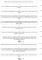
FIG. 1 is a flowchart of a control method for an electric tool; -
FIG. 2 is a flowchart of a control method for an electric tool; -
FIG. 3 is a preferred flowchart of calculating a slope value according to an embodiment; -
FIG. 4 is a schematic structural diagram of a control apparatus for an electric tool according to an embodiment; -
FIG. 5 is a schematic structure diagram of a circuit structure of an electric tool according to an embodiment; -
FIG. 6 is a front view of the appearance and structure of an electric tool according to an embodiment; and -
FIG. 7 is a top view of the appearance and structure of an electric tool according to an embodiment. - The technical solutions of the present invention will be described clearly and completely with reference to the accompanying drawings. The described embodiments are some embodiments, instead of all embodiments, helping to understand the invention as claimed in
claims 1 and 4. - Firstly, a first concept is described in detail as follows with reference to
FIG. 1 to FIG. 7 . - According to an embodiment under the first concept, a control method for an electric motor of an electric tool is provided, and the method may be performed by a processor in the electric tool, and
FIG. 1 shows a first preferred embodiment of the control method. In this embodiment, the control method for an electric motor includes the following steps. - S1: Obtain current values during a running process of the electric tool. Besides the current values, voltage values, power values, and so on may also be obtained, and any parameters that can characterize an output shaft load are feasible. The current values are used as an example. A current collection circuit may be used to collect n current values I1...In when the electric motor of the electric tool rotates to reach a certain time point. Then, the processor obtains the current values. In addition, since an inrush current phenomenon occurs when the electric motor is just turned on, running current values obtained in the solution should be current values collected after the inrush current phenomenon ends. For example, the collection circuit may wait for a while to avoid the inrush current phenomenon, then begin to collect current values, and send the current values to the processor to perform following computation.
- S2: Calculate average current values according to a composite average algorithm. The composite average algorithm includes a combination of at least two average algorithms. There are various types of average algorithms, such as an arithmetical average algorithm, a sliding average algorithm, a geometrical average algorithm, a weighing average algorithm and so on. The present composite average algorithm can use a combination of any two of the plurality of average algorithms to calculate average values. For example, firstly, a certain algorithm is used to calculate average values, secondly, another algorithm is used to calculate average values again based on a calculation result of the first algorithm, and so on, and the average calculation may be performed at least twice. To enhance calculation efficiency, a combination of the arithmetical average algorithm and the sliding average algorithm is preferably used in this embodiment as the foregoing composite average algorithm.
- The quantity of current values, the quantity of calculated average current values, and the quantity of times of average calculation used during the foregoing calculation process may be set as required and according to computation capability and data storage capability of the processor and a memory.
- S3: Calculate slope values of the currents according to the average current values. That is, calculate a plurality of slope values K1...Kn according to the plurality of average current values
I1 ...In. The slopes may be calculated through a plurality of methods. For example, a linear regression method and a difference method are both feasible. To facilitate following determining, the calculated slope values may be magnified for a predetermined quantity of times. - S4: Interrupt torque output of the electric tool according to the slope values of the currents. Data such as a slope value when a fastener reaches an expected position may be measured through experiments, and a condition for interrupting the torque output is determined according to experimental data. For example, a threshold range or a change trend of the slope value is set according to the experimental data. When the slope value falls in a set threshold range or the change trend meets a predetermined change trend, the electric motor is controlled to stop torque output. A torque may be interrupted by one or more different methods, including, but not limited to, interrupting a power provided for the electric motor, reducing the power provided for the electric motor, braking the electric motor efficiently, or motivating a mechanical clutch disposed between the electric motor and an output mandrel. In an exemplary embodiment, a torque is interrupted by braking the electric motor, thereby setting the fastener at an expected position.
- The control method for an electric motor of an electric tool according to an embodiment calculates average current values through the composite average algorithm and calculates slope values according to the plurality of average current values. The slope values calculated in this manner can reflect an actual working condition of the electric motor more accurately, and subsequently, the slope values may be used as a judgment basis for controlling torque output, reduce a misjudgment rate of a shutdown control, and enhance efficiency of an automatic fastening operation.
-
FIG. 2 is a flowchart of a control method for an electric tool according to a second preferred embodiment under the first concept. This embodiment is different from the first preferred embodiment in that, in this embodiment, a step corresponding to step S2 in the first preferred embodiment may further include the following sub-steps. - S21: Use the arithmetical average algorithm to calculate average current values
I of the currents I. It is assumed that n actual current values I1...In during a running process are collected in a certain time period. If an average value is calculated for every three values, several arithmetical average valuesI1 =(I1+I2+I3)/3,I2 =(I4+I5+I6)/3, ...,In =(In-1+I n-2+In)/3 may be obtained. If an average value is calculated for every five values, several arithmetical average valuesI1 =(I1+I2+I3+I4+I5)/5,I2 = (I6+I7+I8+I9+I10)/5, ..., andIn =(In-1+I n-2+I n-3+I n-4+In)/5 may be obtained. - S22: Use the sliding average algorithm to calculate average values of the average current values
I. That is, the sliding average calculation is performed based on the result of the arithmetical average calculation. If the sliding average calculation is performed for every three average current valuesI, several sliding average valuesI' 1=(I1 +I2 +I3 )/3,I' 2=(I2 +I3 +I4 )/3, ..., andI' n=(I n -1+I n-2+In )/3 may be obtained. If the sliding average calculation is performed for every five average current valuesI, several sliding average valuesI' 1=(I1 +I2 +I3 +I4 +I5 )/5,I' 2=(I2 +I3 +I4 +I5 +I6 )/5, ..., andI' n=(I n -1+I n-2+ I n-3+ I n-4+ In)/5 may be obtained. In other implementations, the sliding average algorithm may also be used to calculate average current values firstly, and then the arithmetical average algorithm is used to calculate average values of average current values. That is, the sequence of performing steps S21 and S22 is not limited in the embodiments. - The average current values calculated sequentially according to the arithmetical average algorithm and the sliding average algorithm can reflect an actual working condition of the electric motor more accurately and provide more reliable data for a following shutdown control.
- Furthermore, to enhance credibility of the current values, the sliding average calculation may be performed a plurality of times in step S22. That is, the sliding average algorithm is used to iterate calculation of average values of the average current values I for N times, wherein N≥2, and the specific iteration operation is to take a result of previous average computation as a data source of next average computation.
- Specifically,
I 1 '...In ' obtained in step S22 are results of the first sliding average calculation, and a next iteration calculation is performed depending on the results, so as to obtain second sliding average current valuesI" 1=(I' 1+I' 2+I' 3+I' 4+I' 5)/5,I" 2=(I' 2+I' 3+I' 4+I' 5+I' 6)/5, ..., andI" n=(I' n-1+I 'n-2+I 'n-3+I' n-4+I' n)/5. In a similar way, on the basis of this, the third sliding average calculation may also be performed to obtainI ‴1=(I "1+I "2+I "3+I "4+I "5)/5,I ‴2=(I "2+I "3+I "4+I "5+I "6)/5, ..., andI ‴n=(I "n-1+I " n-2+I " n-3+I " n-4+I "n)/5. The actual quantity of iteration times may be considered with reference to an actual fluctuation condition of currents and computation costs. In this embodiment, N=3, that is, iteration is performed three times to obtain finally required average current valuesI ‴1 ...I ‴n. - If the value of N is 2, iteration is performed twice, that is,
I "1...I "n are taken as final results. - This embodiment is further different from the first preferred embodiment in that, in this embodiment, a step corresponding to step S3 in the first preferred embodiment further includes the following sub-steps.
- S31: Determine time points corresponding to two neighboring average current values, so as to determine a time t between calculating the two neighboring average current values.
- S32: Use a method of dividing a difference between two neighboring average current values by a difference between corresponding time points to calculate a slope value of the currents. That is, the slope value Ki=(
I ‴i-I ‴i-1)/t, and t represents a time between calculatingI ‴I and calculatingI ‴i-1. - More preferably, the slope value may also be calculated by using a mean algorithm.
FIG. 3 is another preferred flowchart of calculating a slope value. That is, a step corresponding to step S3 in the first preferred embodiment may further include the following sub-steps. - S'31: Determine time points corresponding to two neighboring average current values.
- S'32: Use a method of dividing a difference between two neighboring average current values by a difference between corresponding time points to calculate primary slope values of the currents. Step S'31 and step S'32 are the same as step S31 and step S32, and after a period of time, a plurality of slope values k1...kn may be calculated.
- S'33: Use the average algorithm to calculate average slope values of the primary slope values. For example, if an average value is calculated for every five values,
K =(ki+...+ki+4)/5, and furthermore, if an average value is calculated for every three values,K =(ki+...+ki+2)/3. - The foregoing preferred solution uses slope values calculated at a plurality of time points to perform average computation to obtain finally required slope values, and the average slope values are closer to an actual working condition and can enhance accuracy of a following shutdown control operation. To enhance the computation efficiency, during the foregoing process of calculating average slope values, this embodiment preferably performs primary arithmetical average computation.
- In this embodiment, a step corresponding to step S4 in the first preferred embodiment may include the following sub-steps.
- S41: Determine a slope threshold and a triggering condition according to a load of the electric tool. The load may be a current power value or current value of the electric motor or another value of a parameter reflecting an output shaft load, or a current value calculated in the foregoing step. For example, the average current value at a certain time calculated in step S21 or step S22 is
Ij , and according toIj , a slope threshold may be determined specifically through a table look-up manner, that is, a slope threshold comparison table is preset, different average current value ranges correspond to different slope thresholds, and then, a most suitable slope threshold may be determined according to an actual working condition, so as to modify a value of a counter more accurately, be closer to the actual working condition, and then further enhance efficiency of a shutdown control. - The triggering condition in this embodiment is a condition related to the slope value. A person skilled in the art can understand that, the triggering condition of the electric tool usually is not a simple threshold comparison result obtained by one comparison, but a series of comparison results obtained by a plurality of continuous comparisons. Furthermore, for a different working condition, the triggering condition is also different. Therefore, there is a plurality of types of triggering conditions in the art, and the triggering condition, similar to the slope threshold, may also be determined according to a current load condition.
- Furthermore, when the load of the electric tool is greater than the first load, the slope threshold is determined as the first slope threshold, and when the load of the electric tool is less than the first load, the slope threshold is determined as the second slope threshold. The second slope threshold is less than the first slope threshold. That is, when the load is large, the slope threshold is large, and when the load is small, the slope threshold is small.
- Furthermore, when the load of the electric tool is greater than the first load, the triggering condition is that the slope values of the currents calculated at the N continuous time points are all greater than the first slope threshold. For example, the slope values K calculated at the five time points i ms, (i+25) ms, (i+75) ms, (i+100) ms are all greater than the slope threshold, and then torque output is interrupted.
- When the load of the electric tool is less than the first load, the triggering condition is that the slope values of the currents calculated at the first M time points among the N continuous time points are all greater than the second slope threshold, and at least a part of the slope values of the currents calculated at the latter N-M time points are less than the second slope threshold. For example, the slope values K calculated at the three time points i ms, (i+25) ms, and (i+75) ms are all greater than the slope threshold, and the slope values K calculated at the two time points (i+100) ms and (i+125) ms are both less than the slope threshold, and then, torque output is interrupted.
- In the preferred solution, different slope thresholds and shutdown triggering conditions are set for different working conditions, so as to adapt to different working environments, thereby enhancing accuracy and efficiency of an automatic control operation.
- Preferably, the slope thresholds include at least three different slope thresholds, and the triggering conditions corresponding to at least a part of different slope thresholds are different. For example, three different slope thresholds are Kx, Ky, and Kz, Kx may correspond to a first triggering condition, and Ky and Kz correspond to a second triggering condition. More preferably, three to nine different slope thresholds are set according to different working conditions. When nine different slope thresholds K1-K9 are set according to the load, K1 and K2 correspond to the same triggering condition, K3-K5 correspond to the same triggering condition, and K6, K7, K8, and K9 correspond to different triggering conditions respectively. Of course, other corresponding relations are also possible and will not be listed one by one herein.
- S42: Compare the calculated slope values of the N neighboring currents with the slope threshold respectively. For example, K=40 at the ith ms after the electric motor begins to run, K=50 at the (i+25)th ms, K=60 at the (i+50)th ms, K=65 at the (i+75)th ms, and K=70 at the (i+100)th ms, and relations between K and the slope threshold are determined respectively at the five time points, i ms, (i+25) ms, (i+75) ms, and (i+100) ms. According to the plurality of K, it can be known that, the cycle for calculating the slope value in this embodiment is 25 ms, that is, an average slope value is calculated every 25 ms, and in other preferred manners, the calculation cycle may be set according to hardware performance and actual demand. For example, 10 ms, 50 ms, or a shorter or longer calculation cycle is feasible, and the calculation cycle is not limited.
- S43: Determine whether a comparison result meets the triggering condition, and interrupt the torque output of the electric tool when the comparison result meets the triggering condition. After the slope threshold is determined, in a series of comparisons as described above, the slope values at some time points may be possibly greater than the slope threshold, the slope values at other time points may be possibly less than the slope threshold, and the series of comparison results may form a comparison result change trend of slopes and thresholds, and if the change trend meets the shut-down condition determined before, torque output is interrupted.
- In a specific embodiment, a counter may be used to measure the change trend of a relation between slope values and thresholds. Specifically, after the slope values are compared with the threshold, the value of the counter may be modified according to the comparison results, that is, the value of the counter is increased or reduced, and at the same time, the values of the counter at the foregoing five time points are recorded respectively.
- It is assumed that K=40 at the ith ms, K=50 at the (i+25)th ms, K=60 at the (i+50)th ms, K=65 at the (i+75)th ms, and K=70 at the (i+100)th ms, the slope threshold is 50, the initial value of the counter is 0, and the modification rule is to add 1 when the slope value is greater than 50, subtract 1 when the slope value is less than 50, and when the value of the counter is 0, no subtraction is performed. The values of the counter at the foregoing five time points are sequentially 0, 1, 2, 3, and 4, and it can be learned that the value of the counter is increased continuously, and the change trend of the value of the counter may serve as the foregoing triggering condition.
- Another embodiment under the first concept further provides a controlling apparatus for an electric tool, and as shown in
FIG. 4 , the apparatus includes: - an obtaining
unit 21, configured to obtain parameters characterizing an output shaft load during a running process of the electric tool, the parameters possibly being current values; - an average
parameter calculation unit 22, configured to calculate average current values according to a composite average algorithm, the composite average algorithm including a combination of at least two average algorithms; - a slope
value calculation unit 23, configured to calculate slope values of the currents according to the average current values; and - an
execution unit 24, configured to interrupt torque output of the electric tool according to the slope values of the currents. - The control apparatus for an electric motor of an electric tool according to an embodiment of the present invention calculates average current values through the composite average algorithm, and calculates slope values according to the plurality of average current values. The calculated slope values can reflect the actual working condition of the electric motor more accurately, and may be used as a judgment basis for controlling torque output subsequently, thereby reducing a misjudgment rate of a shutdown control and enhancing efficiency of an automatic fastening operation.
- Preferably, the composite average algorithm used by the average
parameter calculation unit 22 of the apparatus is a combination of an arithmetical average algorithm and a sliding average algorithm. - Preferably, the average
parameter calculation unit 22 may include: - an arithmetical average calculation unit, configured to use the arithmetical average algorithm to calculate average currents
I of the currents I; and - a sliding average calculation unit, configured to use the sliding average algorithm to calculate average values of the average currents
I. - The average current values calculated sequentially according to the arithmetical average algorithm and the sliding average algorithm in the preferred solution can reflect the actual working condition of the electric motor more accurately, and provide more reliable data for a following shutdown control.
- Furthermore, to enhance the credibility of the current values, the sliding average calculation unit uses the sliding average algorithm to iterate calculation of average values of the average current values I for N times, wherein N≥2, and the specific iteration operation is to take a result of previous average computation as a data source of next average computation.
- In a preferred implementation, the slope
value calculation unit 23 may include: - a time determining unit, configured to determine time points corresponding to two neighboring average current values; and
- a difference calculation unit, configured to use a method of dividing a difference between two neighboring average current values by a difference between corresponding time points to calculate slope values of the currents.
- In another preferred implementation, the slope
value calculation unit 23 may include: - a time determining unit, configured to determine time points corresponding to two neighboring average current values;
- a difference calculation unit, configured to use a method of dividing a difference between two neighboring average current values by a difference between corresponding time points to calculate primary slope values of the currents; and
- an average slope value calculation unit, configured to use the average algorithm to calculate slope values of the currents according to the primary slope values of the plurality of neighboring time points.
- Furthermore, the average algorithm used by the average slope value calculation unit preferably performs primary arithmetical average computation.
- According to the present invention, the
execution unit 24 includes: - an execution condition setting unit, configured to determine a slope threshold and a triggering condition according to the load of the electric tool;
- a slope comparison unit, configured to compare the calculated slope values of the N neighboring currents with the slope threshold respectively; and
- a judging unit, configured to determine whether a comparison result meets the triggering condition, and interrupt the torque output of the electric tool when the comparison result meets the triggering condition.
- Furthermore, when a load of the electric tool is greater than a first load, the slope threshold is a first slope threshold, when the load of the electric tool is less than a first load, the slope threshold is a second slope threshold, and the second slope threshold is less than the first slope threshold.
- When the load of the electric tool is greater than the first load, the triggering condition is that the slope values of the currents calculated at the N continuous time points are all greater than the first slope threshold.
- When the load of the electric tool is less than the first load, the triggering condition is that the slope values of the currents calculated at the first M time points among the N continuous time points are all greater than the second slope threshold, and at least a part of the slope values of the currents calculated at the latter N-M time points are less than the second slope threshold.
- Preferably, the slope thresholds include at least three different slope thresholds, and the triggering conditions corresponding to at least a part of different slope thresholds are different.
- Another embodiment under the first concept further provides an electric tool, and as shown in
FIG. 5 , the tool includes anelectric motor 31, adrilling bit 32, aparameter collection unit 33, and thecontrol apparatus 34 for an electric tool provided in the foregoing embodiments. Theelectric motor 31 is configured to drive thedrilling bit 32 to rotate. Theparameter collection unit 33 is configured to collect parameters of theelectric motor 31 characterizing an output shaft load, and with reference to the foregoing embodiments, the parameters may be current values. Thecontrol apparatus 34 for an electric tool may obtain current values collected by theparameter collection unit 33, and perform a control operation as described in the foregoing embodiments on the electric motor. - For example, when the
control apparatus 34 determines and calculates the current values collected byparameter collection unit 33, as described in the foregoing embodiments, and determines that an interruption condition is met, thecontrol apparatus 34 may send a control instruction for interrupting torque output to theelectric motor 31, so as to make theelectric motor 31 stop rotation. - The
control apparatus 34 may be a central processing unit (CPU), a microcontroller, a field-programmable gate array (FPGA), and so on. The members may be disposed in a housing of the electric tool as shown inFIG. 6 and FIG. 7 . - To avoid an inrush current phenomenon, the
parameter collection unit 33 may monitor whether theelectric motor 31 is started and collect running current values of theelectric motor 31 continuously after waiting for a predetermined time period when theelectric motor 31 is started. - Regarding the electric tool according to an embodiment, the current signal collection circuit may collect running currents of the electric motor in real time, and the control apparatus calculates average current values through the composite average algorithm, and calculates slope values according to the plurality of average current values. Thus, the calculated slope values can reflect an actual working condition of the electric motor more accurately, and subsequently, the slope values may be used as a judgment basis for controlling torque output of the electric motor, reduce a misjudgment rate of a shutdown control, and enhance efficiency of an automatic fastening operation.
- In a preferred implementation, the electric tool may further include:
amode setting apparatus 35, configured to set a working mode of theelectric motor 31. Thecontrol apparatus 34 controls the electric motor in a predetermined working mode, and themode setting apparatus 35 sets a working mode of theelectric motor 31 through thecontrol apparatus 34. - Furthermore, the foregoing working modes include at least a drilling mode and a screwdriver mode, and in this embodiment, the screwdriver mode is used as the predetermined working mode.
- Preferably, the
mode setting apparatus 35 may include a key unit 351 configured to receive a user operation and a mode selection unit configured to set the working mode of the electric motor according to the user operation. The key unit 351 may be disposed at a position shown inFIG. 6 and FIG. 7 , so that a user can operate conveniently. In this embodiment, the key unit 351 has two keys respectively corresponding to the drilling mode and the screwdriver mode. The mode selection unit may be set inside the housing, the two keys may send an electric signal to the mode selection unit respectively, and according to the received electric signal, the mode selection unit sends a mode setting instruction to theelectric motor 31 to set a working mode of theelectric motor 31. - In the foregoing embodiments, the control method, the control apparatus and the electric tool all determine a load condition of an output shaft of a current electric tool through obtaining current values of the electric tool during a running process, and perform a corresponding control according to a working condition reflected by the load condition. In other embodiments, the load condition of the output shaft of the current electric tool may also be obtained through obtaining various parameters of the electric motor of the electric tool during a running process, such as a rotation speed of the electric motor, a voltage of the electric motor, a voltage change of a power supply and a torque of an output shaft, and a corresponding control is performed according to a working condition reflected by the load condition. That is, the control method and the control apparatus provided can also calculate average values of parameters characterizing an output shaft load according to the composite average algorithm through obtaining parameters characterizing the output shaft load, calculate the slope values according to the average values, and interrupt torque output of the electric tool according to the slope values.
- Accordingly, the electric tool includes a sensor configured to collect parameters characterizing the output shaft load.
- Obviously, the embodiments are only to describe the examples clearly, instead of limiting the implementations. A person of ordinary skill in the art can further make other different forms of variations or modifications on the basis of the foregoing description. The implementations cannot be listed exhaustively herein.
- The electric screwdriver is used as an example for description. Of course, the control method of the present invention may also be applied to other electric tools, such as an electric drill and an electric spanner. The application may be implemented by a person of ordinary skill in the art easily according to the foregoing implementations, and will not be repeated by the applicant herein.
Claims (13)
- A control method for an electric tool, comprising:obtaining parameters characterizing an output shaft load during a running process of an electric tool;calculating average values of the parameters characterizing the output shaft load according to a composite average algorithm, wherein the composite average algorithm comprises a combination of at least two different types of average algorithms;calculating slope values of the parameters characterizing the output shaft load according to the average values of the parameters characterizing the output shaft load; andinterrupting torque output of the electric tool according to the slope values of the parameters characterizing the output shaft load,wherein the step of interrupting torque output of the electric tool according to the slope values of the parameters characterizing the output shaft load comprises:determining a slope threshold and a triggering condition according to a load of the electric tool;comparing calculated slope values of N neighboring parameters characterizing the output shaft load with the slope threshold respectively; anddetermining whether a comparison result meets the triggering condition, and when the comparison result meets the triggering condition, interrupting torque output of the electric tool, andcharacterised in thatwhen the load of the electric tool is greater than a first load, the slope threshold is a first slope threshold, when the load of the electric tool is less than the first load, the slope threshold is a second slope threshold, and the second slope threshold is less than the first slope threshold.
- The control method according to claim 1, wherein the step of calculating average values of the parameters characterizing the output shaft load according to a composite average algorithm comprises:calculating average parameters of the parameters characterizing the output shaft load by using an arithmetical average algorithm; andcalculating average values of the average parameters by using the sliding average algorithm.
- The method according to claim 1, wherein the step of calculating slope values of the parameters characterizing the output shaft load according to the average values of the parameters characterizing the output shaft load comprises:determining time points corresponding to the average values of two neighboring parameters characterizing the output shaft load;calculating primary slope values of the parameters characterizing the output shaft load by using a method of dividing a difference between the average values of the two neighboring parameters characterizing the output shaft load by a difference between the corresponding time points; andcalculating average slope values of the primary slope values by using an average algorithm.
- A control apparatus (34) for an electric tool, comprising:an obtaining unit (21), configured to obtain parameters characterizing an output shaft load during a running process of an electric tool;an average parameter calculation unit (22), configured to calculate average values of the parameters characterizing the output shaft load according to a composite average algorithm, wherein the composite average algorithm comprises a combination of at least two different types of average algorithms;a slope value calculation unit (23), configured to calculate slope values of the parameters characterizing the output shaft load according to the average values of the parameters characterizing the output shaft load; andan execution unit (24), configured to interrupt torque output of the electric tool according to the slope values of the parameters characterizing the output shaft load,wherein the execution unit comprises:an execution condition setting unit, configured to determine a slope threshold and a triggering condition according to a load of the electric tool;a slope comparison unit, configured to compare the calculated slope values of the N neighboring parameters characterizing the output shaft load with the slope threshold respectively;a judging unit, configured to determine whether a comparison result meets the triggering condition, and interrupt torque output of the electric tool when the comparison result meets the triggering condition,characterised in thatwhen the load of the electric tool is greater than a first load, the slope threshold is a first slope threshold, when the load of the electric tool is less than the first load, the slope threshold is a second slope threshold, and the second slope threshold is less than the first slope threshold.
- The control method according to claim 1 or the apparatus according to claim 4 wherein the different types of average algorithms are used alternately to calculate the average values and the average calculation is performed at least twice.
- The method according to claim 1 or 5 or the apparatus according to claim 4 or 5, wherein the composite average algorithm is a combination of an arithmetical average algorithm and a sliding average algorithm.
- The apparatus according to claim 4, wherein the average parameter calculation unit comprises:an arithmetical average calculation unit, configured to calculate average parameters of the parameters characterizing the output shaft load by using an arithmetical average algorithm; anda sliding average calculation unit, configured to calculate average values of average parameters by using a sliding average algorithm.
- The method according to claim 2 or the apparatus according to claim 7, wherein the steps of calculating average values of average parameters by using a sliding average algorithm comprises: iterating calculation of the average values of the average parameters for N times by using the sliding average algorithm, wherein N≥2, and a specific iteration operation is to take a result of previous average computation as a data source of next average computation.
- The apparatus according to claim 4, wherein the slope value calculation unit comprises:a time determining unit, configured to determine time points corresponding to the average values of two neighboring parameters characterizing the output shaft load;a difference calculation unit, configured to calculate primary slope values of the parameters characterizing the output shaft load by using a method of dividing a difference between the average values of the two neighboring parameters characterizing the output shaft load by a difference between the corresponding time points; andan average slope value calculation unit, configured to calculate average slope values of the primary slope values by using the average algorithm.
- The method according to claim 1 or apparatus according to claim 4, wherein when the load of the electric tool is greater than the first load, the triggering condition is that the slope values of the parameters characterizing the output shaft load calculated at N continuous time points are all greater than the first slope threshold; or
wherein when the load of the electric tool is less than the first load, the triggering condition is that the slope values of the parameters characterizing the output shaft load calculated at the first M time points among N continuous time points are all greater than the second slope threshold, and at least a part of the slope values of the parameters characterizing the output shaft load calculated at the latter N-M time points are less than the second slope threshold. - The method according to claim 1 or apparatus according to claim 4, wherein the slope thresholds comprise at least three different slope thresholds, and the triggering conditions corresponding to at least a part of the different slope thresholds are not the same.
- An electric tool, comprising an electric motor (31) and an output shaft, wherein the electric motor is configured to drive the output shaft to move and the electric tool further comprises:a parameter collection unit (33), configured to collect parameters characterizing an output shaft load during a running process of the electric motor; andthe control apparatus (34) for an electric tool according to any one of claims 4 to 11.
- The electric tool according to claim 12, further comprising:a mode setting apparatus (35), configured to set working modes of the electric motor comprising at least a drilling mode and a screwdriver mode;wherein the control apparatus (34) controls the electric motor in the screwdriver mode.
Applications Claiming Priority (2)
| Application Number | Priority Date | Filing Date | Title |
|---|---|---|---|
| CN201610480495.1A CN107544426B (en) | 2016-06-27 | 2016-06-27 | Control method and device of electric tool and electric tool |
| PCT/CN2017/090409 WO2018001255A1 (en) | 2016-06-27 | 2017-06-27 | Method and apparatus for controlling electric tool, and electric tool |
Publications (3)
| Publication Number | Publication Date |
|---|---|
| EP3476509A1 EP3476509A1 (en) | 2019-05-01 |
| EP3476509A4 EP3476509A4 (en) | 2020-02-12 |
| EP3476509B1 true EP3476509B1 (en) | 2025-06-25 |
Family
ID=60786581
Family Applications (1)
| Application Number | Title | Priority Date | Filing Date |
|---|---|---|---|
| EP17819252.2A Active EP3476509B1 (en) | 2016-06-27 | 2017-06-27 | Method and apparatus for controlling electric tool, and electric tool |
Country Status (5)
| Country | Link |
|---|---|
| US (1) | US10962950B2 (en) |
| EP (1) | EP3476509B1 (en) |
| JP (1) | JP6698182B2 (en) |
| CN (1) | CN107544426B (en) |
| WO (1) | WO2018001255A1 (en) |
Families Citing this family (7)
| Publication number | Priority date | Publication date | Assignee | Title |
|---|---|---|---|---|
| WO2020200188A1 (en) * | 2019-04-04 | 2020-10-08 | 南京德朔实业有限公司 | Smart electric tool and system having same, and control method |
| CN113561113B (en) * | 2020-04-28 | 2022-09-20 | 南京泉峰科技有限公司 | Intelligent electric tool and control method thereof |
| JP7465190B2 (en) * | 2020-10-12 | 2024-04-10 | パナソニックホールディングス株式会社 | Electric tool, motor control method and program |
| CN114453620B (en) * | 2020-11-09 | 2024-01-05 | 南京泉峰科技有限公司 | Intelligent electric tools and control methods thereof |
| US12627107B2 (en) | 2021-08-11 | 2026-05-12 | Milwaukee Electric Tool Corporation | System and methods for determining crimp applications and reporting power tool usage |
| US12489382B2 (en) | 2021-12-15 | 2025-12-02 | Milwaukee Electric Tool Corporation | Adaptive trigger mapping |
| CN114301373B (en) * | 2021-12-30 | 2024-03-22 | 深圳市汇川技术股份有限公司 | Motor control method, equipment and storage medium |
Citations (1)
| Publication number | Priority date | Publication date | Assignee | Title |
|---|---|---|---|---|
| US20140284070A1 (en) * | 2012-06-08 | 2014-09-25 | Black & Decker Inc. | Operating mode indicator for a power tool |
Family Cites Families (25)
| Publication number | Priority date | Publication date | Assignee | Title |
|---|---|---|---|---|
| US3926264A (en) * | 1973-11-23 | 1975-12-16 | Thor Power Tool Co | Control circuit for a power tool |
| JP3108546B2 (en) * | 1992-09-25 | 2000-11-13 | 株式会社東芝 | Detector redundancy system error handling device |
| GB9320181D0 (en) * | 1993-09-30 | 1993-11-17 | Black & Decker Inc | Improvements in and relating to power tools |
| JP3514529B2 (en) * | 1994-06-06 | 2004-03-31 | 沖電気工業株式会社 | Multi-level FSK detection circuit |
| JP4292725B2 (en) * | 2001-03-22 | 2009-07-08 | パナソニック電工株式会社 | Tightening tool |
| US7110924B2 (en) * | 2002-05-15 | 2006-09-19 | Caterpillar Inc. | Method for controlling the performance of a target system |
| JP2006015438A (en) * | 2004-06-30 | 2006-01-19 | Matsushita Electric Works Ltd | Impact fastening tool |
| EP2046535B1 (en) * | 2006-08-02 | 2019-03-13 | Wallace, Margaret | A method and apparatus for determining when a threaded fastener has been tightened to a predetermined tightness |
| US7432721B2 (en) * | 2006-12-18 | 2008-10-07 | Temic Automotive Of North America, Inc. | Solenoid actuator motion detection |
| CN101082822A (en) * | 2007-06-01 | 2007-12-05 | 张建华 | Control method of vehicle DC electric machine |
| CN101771379B (en) * | 2009-01-04 | 2015-02-04 | 苏州宝时得电动工具有限公司 | Control method of electric tool and electric tool implementing the control method |
| JP5483089B2 (en) * | 2010-03-11 | 2014-05-07 | 日立工機株式会社 | Impact tools |
| JP5576819B2 (en) * | 2011-03-23 | 2014-08-20 | パナソニック株式会社 | Lighting device and lighting apparatus |
| KR101234669B1 (en) * | 2011-12-08 | 2013-02-19 | 현대자동차주식회사 | Method for current correction of dc-dc converter a green car |
| DE102011089910A1 (en) * | 2011-12-27 | 2013-06-27 | Robert Bosch Gmbh | Hand tool device |
| US9908182B2 (en) * | 2012-01-30 | 2018-03-06 | Black & Decker Inc. | Remote programming of a power tool |
| JP5965694B2 (en) * | 2012-03-29 | 2016-08-10 | 株式会社バンガードシステムズ | Screw tightening device and control method |
| US20130327552A1 (en) * | 2012-06-08 | 2013-12-12 | Black & Decker Inc. | Power tool having multiple operating modes |
| CN103678322B (en) * | 2012-09-03 | 2016-12-28 | 阿里巴巴集团控股有限公司 | The integration system of a kind of sample data and method |
| CN105227013B (en) * | 2014-06-30 | 2018-01-16 | 南京德朔实业有限公司 | A kind of electric tool and its control method |
| CN104133388B (en) * | 2014-07-04 | 2016-06-08 | 北京航空航天大学 | A kind of multifunctional sampling instrument control device and control method thereof |
| CN104090189B (en) * | 2014-07-21 | 2017-12-15 | Tcl集团股份有限公司 | A kind of equipment working state detection method and equipment working state detection means |
| US9808591B2 (en) * | 2014-08-15 | 2017-11-07 | Covidien Lp | Methods and systems for breath delivery synchronization |
| CN104656551B (en) * | 2014-09-02 | 2016-09-14 | 苏州宝时得电动工具有限公司 | The control method of electric tool and system, electric tool |
| US10115567B2 (en) * | 2014-09-17 | 2018-10-30 | Tokyo Electron Limited | Plasma processing apparatus |
-
2016
- 2016-06-27 CN CN201610480495.1A patent/CN107544426B/en active Active
-
2017
- 2017-06-27 JP JP2018567946A patent/JP6698182B2/en active Active
- 2017-06-27 EP EP17819252.2A patent/EP3476509B1/en active Active
- 2017-06-27 WO PCT/CN2017/090409 patent/WO2018001255A1/en not_active Ceased
-
2018
- 2018-12-21 US US16/229,747 patent/US10962950B2/en active Active
Patent Citations (1)
| Publication number | Priority date | Publication date | Assignee | Title |
|---|---|---|---|---|
| US20140284070A1 (en) * | 2012-06-08 | 2014-09-25 | Black & Decker Inc. | Operating mode indicator for a power tool |
Also Published As
| Publication number | Publication date |
|---|---|
| EP3476509A4 (en) | 2020-02-12 |
| US10962950B2 (en) | 2021-03-30 |
| JP2019525845A (en) | 2019-09-12 |
| CN107544426B (en) | 2021-09-07 |
| US20190187659A1 (en) | 2019-06-20 |
| EP3476509A1 (en) | 2019-05-01 |
| WO2018001255A1 (en) | 2018-01-04 |
| JP6698182B2 (en) | 2020-05-27 |
| CN107544426A (en) | 2018-01-05 |
Similar Documents
| Publication | Publication Date | Title |
|---|---|---|
| US10962950B2 (en) | Method and apparatus for controlling electric tool, and electric tool | |
| US11919129B2 (en) | Adaptive impact blow detection | |
| CN101771379B (en) | Control method of electric tool and electric tool implementing the control method | |
| JP7457799B2 (en) | How to operate a manual machine tool and a manual machine tool | |
| JP5780896B2 (en) | Electric tool | |
| CN108370152B (en) | Overload detection in power tools | |
| CN100441868C (en) | Apparatus and method for controlling compressor operation | |
| US12145242B2 (en) | Method for detecting a first operating state of a handheld power tool | |
| CN117279745A (en) | Power tools including machine learning module for controlling field weakening of permanent magnet motors | |
| CN106483846B (en) | Control method of electric tool and electric tool for executing control method | |
| CN216657837U (en) | Electric tool | |
| CN103386665B (en) | Control method of electric tool and electric tool used for executing control method | |
| US20240256961A1 (en) | Method for Generating a Training Dataset, Method for Training an Artificial Intelligence Means, Artificial Intelligence Means, and Hand-Held Power Tool | |
| CN118393865A (en) | Method for controlling a hand-held power tool and hand-held power tool | |
| US20240139916A1 (en) | Impact tool including an electronic clutch | |
| CN118393861A (en) | Method for selecting data for training an artificial intelligence system, method for generating a training data set and training data set | |
| CN118393870A (en) | Method for selecting data for training artificial intelligence, method for generating training data set, training data set | |
| CN118393869A (en) | Method for controlling a hand-held power tool and hand-held power tool | |
| CN118393862A (en) | Method for controlling a hand-held power tool and hand-held power tool | |
| JP7791886B2 (en) | Method for operating a manual machine tool and manual machine tool | |
| WO2021016886A1 (en) | Gimbal control method, gimbal, and computer-readable storage medium | |
| TWI576213B (en) | Torsion control method and device for electric impact power tool | |
| CN113561113A (en) | Intelligent electric tool and control method thereof | |
| EP4212284A1 (en) | Impact rotary tool, torque calculation method, and program | |
| CN106142020A (en) | Utilize the method that trigger controls motor |
Legal Events
| Date | Code | Title | Description |
|---|---|---|---|
| STAA | Information on the status of an ep patent application or granted ep patent |
Free format text: STATUS: THE INTERNATIONAL PUBLICATION HAS BEEN MADE |
|
| PUAI | Public reference made under article 153(3) epc to a published international application that has entered the european phase |
Free format text: ORIGINAL CODE: 0009012 |
|
| STAA | Information on the status of an ep patent application or granted ep patent |
Free format text: STATUS: REQUEST FOR EXAMINATION WAS MADE |
|
| 17P | Request for examination filed |
Effective date: 20181210 |
|
| AK | Designated contracting states |
Kind code of ref document: A1 Designated state(s): AL AT BE BG CH CY CZ DE DK EE ES FI FR GB GR HR HU IE IS IT LI LT LU LV MC MK MT NL NO PL PT RO RS SE SI SK SM TR |
|
| AX | Request for extension of the european patent |
Extension state: BA ME |
|
| DAV | Request for validation of the european patent (deleted) | ||
| DAX | Request for extension of the european patent (deleted) | ||
| REG | Reference to a national code |
Ref country code: DE Ref legal event code: R079 Free format text: PREVIOUS MAIN CLASS: B23B0045020000 Ipc: B25B0023147000 |
|
| A4 | Supplementary search report drawn up and despatched |
Effective date: 20200110 |
|
| RIC1 | Information provided on ipc code assigned before grant |
Ipc: B25B 23/147 20060101AFI20200106BHEP Ipc: B25F 5/00 20060101ALI20200106BHEP Ipc: B23B 45/02 20060101ALI20200106BHEP |
|
| STAA | Information on the status of an ep patent application or granted ep patent |
Free format text: STATUS: EXAMINATION IS IN PROGRESS |
|
| 17Q | First examination report despatched |
Effective date: 20230324 |
|
| P01 | Opt-out of the competence of the unified patent court (upc) registered |
Effective date: 20240312 |
|
| GRAP | Despatch of communication of intention to grant a patent |
Free format text: ORIGINAL CODE: EPIDOSNIGR1 |
|
| STAA | Information on the status of an ep patent application or granted ep patent |
Free format text: STATUS: GRANT OF PATENT IS INTENDED |
|
| INTG | Intention to grant announced |
Effective date: 20241106 |
|
| GRAJ | Information related to disapproval of communication of intention to grant by the applicant or resumption of examination proceedings by the epo deleted |
Free format text: ORIGINAL CODE: EPIDOSDIGR1 |
|
| STAA | Information on the status of an ep patent application or granted ep patent |
Free format text: STATUS: EXAMINATION IS IN PROGRESS |
|
| INTC | Intention to grant announced (deleted) | ||
| GRAP | Despatch of communication of intention to grant a patent |
Free format text: ORIGINAL CODE: EPIDOSNIGR1 |
|
| STAA | Information on the status of an ep patent application or granted ep patent |
Free format text: STATUS: GRANT OF PATENT IS INTENDED |
|
| INTG | Intention to grant announced |
Effective date: 20250408 |
|
| GRAS | Grant fee paid |
Free format text: ORIGINAL CODE: EPIDOSNIGR3 |
|
| GRAA | (expected) grant |
Free format text: ORIGINAL CODE: 0009210 |
|
| STAA | Information on the status of an ep patent application or granted ep patent |
Free format text: STATUS: THE PATENT HAS BEEN GRANTED |
|
| AK | Designated contracting states |
Kind code of ref document: B1 Designated state(s): AL AT BE BG CH CY CZ DE DK EE ES FI FR GB GR HR HU IE IS IT LI LT LU LV MC MK MT NL NO PL PT RO RS SE SI SK SM TR |
|
| REG | Reference to a national code |
Ref country code: GB Ref legal event code: FG4D |
|
| REG | Reference to a national code |
Ref country code: CH Ref legal event code: EP |
|
| PGFP | Annual fee paid to national office [announced via postgrant information from national office to epo] |
Ref country code: DE Payment date: 20250617 Year of fee payment: 9 |
|
| PGFP | Annual fee paid to national office [announced via postgrant information from national office to epo] |
Ref country code: GB Payment date: 20250625 Year of fee payment: 9 |
|
| REG | Reference to a national code |
Ref country code: CH Ref legal event code: EP |
|
| REG | Reference to a national code |
Ref country code: IE Ref legal event code: FG4D |
|
| REG | Reference to a national code |
Ref country code: DE Ref legal event code: R096 Ref document number: 602017090160 Country of ref document: DE |
|
| PGFP | Annual fee paid to national office [announced via postgrant information from national office to epo] |
Ref country code: FR Payment date: 20250630 Year of fee payment: 9 |
|
| PG25 | Lapsed in a contracting state [announced via postgrant information from national office to epo] |
Ref country code: FI Free format text: LAPSE BECAUSE OF FAILURE TO SUBMIT A TRANSLATION OF THE DESCRIPTION OR TO PAY THE FEE WITHIN THE PRESCRIBED TIME-LIMIT Effective date: 20250625 |
|
| REG | Reference to a national code |
Ref country code: LT Ref legal event code: MG9D |
|
| PG25 | Lapsed in a contracting state [announced via postgrant information from national office to epo] |
Ref country code: GR Free format text: LAPSE BECAUSE OF FAILURE TO SUBMIT A TRANSLATION OF THE DESCRIPTION OR TO PAY THE FEE WITHIN THE PRESCRIBED TIME-LIMIT Effective date: 20250926 Ref country code: NO Free format text: LAPSE BECAUSE OF FAILURE TO SUBMIT A TRANSLATION OF THE DESCRIPTION OR TO PAY THE FEE WITHIN THE PRESCRIBED TIME-LIMIT Effective date: 20250925 |
|
| PG25 | Lapsed in a contracting state [announced via postgrant information from national office to epo] |
Ref country code: BG Free format text: LAPSE BECAUSE OF FAILURE TO SUBMIT A TRANSLATION OF THE DESCRIPTION OR TO PAY THE FEE WITHIN THE PRESCRIBED TIME-LIMIT Effective date: 20250625 |
|
| PG25 | Lapsed in a contracting state [announced via postgrant information from national office to epo] |
Ref country code: HR Free format text: LAPSE BECAUSE OF FAILURE TO SUBMIT A TRANSLATION OF THE DESCRIPTION OR TO PAY THE FEE WITHIN THE PRESCRIBED TIME-LIMIT Effective date: 20250625 |
|
| PG25 | Lapsed in a contracting state [announced via postgrant information from national office to epo] |
Ref country code: RS Free format text: LAPSE BECAUSE OF FAILURE TO SUBMIT A TRANSLATION OF THE DESCRIPTION OR TO PAY THE FEE WITHIN THE PRESCRIBED TIME-LIMIT Effective date: 20250925 |
|
| PG25 | Lapsed in a contracting state [announced via postgrant information from national office to epo] |
Ref country code: LV Free format text: LAPSE BECAUSE OF FAILURE TO SUBMIT A TRANSLATION OF THE DESCRIPTION OR TO PAY THE FEE WITHIN THE PRESCRIBED TIME-LIMIT Effective date: 20250625 |
|
| REG | Reference to a national code |
Ref country code: NL Ref legal event code: MP Effective date: 20250625 |
|
| PG25 | Lapsed in a contracting state [announced via postgrant information from national office to epo] |
Ref country code: NL Free format text: LAPSE BECAUSE OF FAILURE TO SUBMIT A TRANSLATION OF THE DESCRIPTION OR TO PAY THE FEE WITHIN THE PRESCRIBED TIME-LIMIT Effective date: 20250625 |
|
| PG25 | Lapsed in a contracting state [announced via postgrant information from national office to epo] |
Ref country code: PT Free format text: LAPSE BECAUSE OF FAILURE TO SUBMIT A TRANSLATION OF THE DESCRIPTION OR TO PAY THE FEE WITHIN THE PRESCRIBED TIME-LIMIT Effective date: 20251027 |
|
| REG | Reference to a national code |
Ref country code: AT Ref legal event code: MK05 Ref document number: 1805993 Country of ref document: AT Kind code of ref document: T Effective date: 20250625 |
|
| PG25 | Lapsed in a contracting state [announced via postgrant information from national office to epo] |
Ref country code: IS Free format text: LAPSE BECAUSE OF FAILURE TO SUBMIT A TRANSLATION OF THE DESCRIPTION OR TO PAY THE FEE WITHIN THE PRESCRIBED TIME-LIMIT Effective date: 20251025 |
|
| PG25 | Lapsed in a contracting state [announced via postgrant information from national office to epo] |
Ref country code: AT Free format text: LAPSE BECAUSE OF FAILURE TO SUBMIT A TRANSLATION OF THE DESCRIPTION OR TO PAY THE FEE WITHIN THE PRESCRIBED TIME-LIMIT Effective date: 20250625 Ref country code: SM Free format text: LAPSE BECAUSE OF FAILURE TO SUBMIT A TRANSLATION OF THE DESCRIPTION OR TO PAY THE FEE WITHIN THE PRESCRIBED TIME-LIMIT Effective date: 20250625 |
|
| PG25 | Lapsed in a contracting state [announced via postgrant information from national office to epo] |
Ref country code: CZ Free format text: LAPSE BECAUSE OF FAILURE TO SUBMIT A TRANSLATION OF THE DESCRIPTION OR TO PAY THE FEE WITHIN THE PRESCRIBED TIME-LIMIT Effective date: 20250625 |
|
| PG25 | Lapsed in a contracting state [announced via postgrant information from national office to epo] |
Ref country code: PL Free format text: LAPSE BECAUSE OF FAILURE TO SUBMIT A TRANSLATION OF THE DESCRIPTION OR TO PAY THE FEE WITHIN THE PRESCRIBED TIME-LIMIT Effective date: 20250625 |
|
| PG25 | Lapsed in a contracting state [announced via postgrant information from national office to epo] |
Ref country code: EE Free format text: LAPSE BECAUSE OF FAILURE TO SUBMIT A TRANSLATION OF THE DESCRIPTION OR TO PAY THE FEE WITHIN THE PRESCRIBED TIME-LIMIT Effective date: 20250625 |
|
| PG25 | Lapsed in a contracting state [announced via postgrant information from national office to epo] |
Ref country code: SK Free format text: LAPSE BECAUSE OF FAILURE TO SUBMIT A TRANSLATION OF THE DESCRIPTION OR TO PAY THE FEE WITHIN THE PRESCRIBED TIME-LIMIT Effective date: 20250625 |
|
| REG | Reference to a national code |
Ref country code: CH Ref legal event code: H13 Free format text: ST27 STATUS EVENT CODE: U-0-0-H10-H13 (AS PROVIDED BY THE NATIONAL OFFICE) Effective date: 20260127 |
|
| PG25 | Lapsed in a contracting state [announced via postgrant information from national office to epo] |
Ref country code: ES Free format text: LAPSE BECAUSE OF FAILURE TO SUBMIT A TRANSLATION OF THE DESCRIPTION OR TO PAY THE FEE WITHIN THE PRESCRIBED TIME-LIMIT Effective date: 20250625 |
|
| PG25 | Lapsed in a contracting state [announced via postgrant information from national office to epo] |
Ref country code: LU Free format text: LAPSE BECAUSE OF NON-PAYMENT OF DUE FEES Effective date: 20250627 |
|
| REG | Reference to a national code |
Ref country code: BE Ref legal event code: MM Effective date: 20250630 |
|
| PG25 | Lapsed in a contracting state [announced via postgrant information from national office to epo] |
Ref country code: RO Free format text: LAPSE BECAUSE OF FAILURE TO SUBMIT A TRANSLATION OF THE DESCRIPTION OR TO PAY THE FEE WITHIN THE PRESCRIBED TIME-LIMIT Effective date: 20250625 |
|
| PG25 | Lapsed in a contracting state [announced via postgrant information from national office to epo] |
Ref country code: MC Free format text: LAPSE BECAUSE OF FAILURE TO SUBMIT A TRANSLATION OF THE DESCRIPTION OR TO PAY THE FEE WITHIN THE PRESCRIBED TIME-LIMIT Effective date: 20250625 |
|
| PG25 | Lapsed in a contracting state [announced via postgrant information from national office to epo] |
Ref country code: DK Free format text: LAPSE BECAUSE OF FAILURE TO SUBMIT A TRANSLATION OF THE DESCRIPTION OR TO PAY THE FEE WITHIN THE PRESCRIBED TIME-LIMIT Effective date: 20250625 Ref country code: IE Free format text: LAPSE BECAUSE OF NON-PAYMENT OF DUE FEES Effective date: 20250627 |
|
| PG25 | Lapsed in a contracting state [announced via postgrant information from national office to epo] |
Ref country code: BE Free format text: LAPSE BECAUSE OF NON-PAYMENT OF DUE FEES Effective date: 20250630 Ref country code: IT Free format text: LAPSE BECAUSE OF FAILURE TO SUBMIT A TRANSLATION OF THE DESCRIPTION OR TO PAY THE FEE WITHIN THE PRESCRIBED TIME-LIMIT Effective date: 20250625 |
|
| PG25 | Lapsed in a contracting state [announced via postgrant information from national office to epo] |
Ref country code: CH Free format text: LAPSE BECAUSE OF NON-PAYMENT OF DUE FEES Effective date: 20250630 |
|
| PLBE | No opposition filed within time limit |
Free format text: ORIGINAL CODE: 0009261 |
|
| STAA | Information on the status of an ep patent application or granted ep patent |
Free format text: STATUS: NO OPPOSITION FILED WITHIN TIME LIMIT |
|
| REG | Reference to a national code |
Ref country code: CH Ref legal event code: L10 Free format text: ST27 STATUS EVENT CODE: U-0-0-L10-L00 (AS PROVIDED BY THE NATIONAL OFFICE) Effective date: 20260507 |