EP3476506B1 - Device for automatically removing burrs from a wheel hub section - Google Patents
Device for automatically removing burrs from a wheel hub section Download PDFInfo
- Publication number
- EP3476506B1 EP3476506B1 EP18203000.7A EP18203000A EP3476506B1 EP 3476506 B1 EP3476506 B1 EP 3476506B1 EP 18203000 A EP18203000 A EP 18203000A EP 3476506 B1 EP3476506 B1 EP 3476506B1
- Authority
- EP
- European Patent Office
- Prior art keywords
- cylinder
- wheel
- support plate
- sliding block
- clamping
- Prior art date
- Legal status (The legal status is an assumption and is not a legal conclusion. Google has not performed a legal analysis and makes no representation as to the accuracy of the status listed.)
- Active
Links
Images


Classifications
-
- B—PERFORMING OPERATIONS; TRANSPORTING
- B24—GRINDING; POLISHING
- B24B—MACHINES, DEVICES, OR PROCESSES FOR GRINDING OR POLISHING; DRESSING OR CONDITIONING OF ABRADING SURFACES; FEEDING OF GRINDING, POLISHING, OR LAPPING AGENTS
- B24B9/00—Machines or devices designed for grinding edges or bevels on work or for removing burrs; Accessories therefor
- B24B9/02—Machines or devices designed for grinding edges or bevels on work or for removing burrs; Accessories therefor characterised by a special design with respect to properties of materials specific to articles to be ground
- B24B9/04—Machines or devices designed for grinding edges or bevels on work or for removing burrs; Accessories therefor characterised by a special design with respect to properties of materials specific to articles to be ground of metal, e.g. skate blades
-
- B—PERFORMING OPERATIONS; TRANSPORTING
- B23—MACHINE TOOLS; METAL-WORKING NOT OTHERWISE PROVIDED FOR
- B23D—PLANING; SLOTTING; SHEARING; BROACHING; SAWING; FILING; SCRAPING; LIKE OPERATIONS FOR WORKING METAL BY REMOVING MATERIAL, NOT OTHERWISE PROVIDED FOR
- B23D79/00—Methods, machines, or devices not covered elsewhere, for working metal by removal of material
-
- B—PERFORMING OPERATIONS; TRANSPORTING
- B22—CASTING; POWDER METALLURGY
- B22D—CASTING OF METALS; CASTING OF OTHER SUBSTANCES BY THE SAME PROCESSES OR DEVICES
- B22D31/00—Cutting-off surplus material, e.g. gates; Cleaning and working on castings
- B22D31/002—Cleaning, working on castings
-
- B—PERFORMING OPERATIONS; TRANSPORTING
- B23—MACHINE TOOLS; METAL-WORKING NOT OTHERWISE PROVIDED FOR
- B23B—TURNING; BORING
- B23B5/00—Turning-machines or devices specially adapted for particular work; Accessories specially adapted therefor
- B23B5/28—Turning-machines or devices specially adapted for particular work; Accessories specially adapted therefor for turning wheels or wheel sets or cranks thereon, i.e. wheel lathes
-
- B—PERFORMING OPERATIONS; TRANSPORTING
- B23—MACHINE TOOLS; METAL-WORKING NOT OTHERWISE PROVIDED FOR
- B23Q—DETAILS, COMPONENTS, OR ACCESSORIES FOR MACHINE TOOLS, e.g. ARRANGEMENTS FOR COPYING OR CONTROLLING; MACHINE TOOLS IN GENERAL CHARACTERISED BY THE CONSTRUCTION OF PARTICULAR DETAILS OR COMPONENTS; COMBINATIONS OR ASSOCIATIONS OF METAL-WORKING MACHINES, NOT DIRECTED TO A PARTICULAR RESULT
- B23Q1/00—Members which are comprised in the general build-up of a form of machine, particularly relatively large fixed members
- B23Q1/25—Movable or adjustable work or tool supports
- B23Q1/26—Movable or adjustable work or tool supports characterised by constructional features relating to the co-operation of relatively movable members; Means for preventing relative movement of such members
-
- B—PERFORMING OPERATIONS; TRANSPORTING
- B23—MACHINE TOOLS; METAL-WORKING NOT OTHERWISE PROVIDED FOR
- B23Q—DETAILS, COMPONENTS, OR ACCESSORIES FOR MACHINE TOOLS, e.g. ARRANGEMENTS FOR COPYING OR CONTROLLING; MACHINE TOOLS IN GENERAL CHARACTERISED BY THE CONSTRUCTION OF PARTICULAR DETAILS OR COMPONENTS; COMBINATIONS OR ASSOCIATIONS OF METAL-WORKING MACHINES, NOT DIRECTED TO A PARTICULAR RESULT
- B23Q3/00—Devices holding, supporting, or positioning work or tools, of a kind normally removable from the machine
- B23Q3/02—Devices holding, supporting, or positioning work or tools, of a kind normally removable from the machine for mounting on a work-table, tool-slide, or analogous part
- B23Q3/06—Work-clamping means
- B23Q3/062—Work-clamping means adapted for holding workpieces having a special form or being made from a special material
-
- B—PERFORMING OPERATIONS; TRANSPORTING
- B23—MACHINE TOOLS; METAL-WORKING NOT OTHERWISE PROVIDED FOR
- B23Q—DETAILS, COMPONENTS, OR ACCESSORIES FOR MACHINE TOOLS, e.g. ARRANGEMENTS FOR COPYING OR CONTROLLING; MACHINE TOOLS IN GENERAL CHARACTERISED BY THE CONSTRUCTION OF PARTICULAR DETAILS OR COMPONENTS; COMBINATIONS OR ASSOCIATIONS OF METAL-WORKING MACHINES, NOT DIRECTED TO A PARTICULAR RESULT
- B23Q3/00—Devices holding, supporting, or positioning work or tools, of a kind normally removable from the machine
- B23Q3/02—Devices holding, supporting, or positioning work or tools, of a kind normally removable from the machine for mounting on a work-table, tool-slide, or analogous part
- B23Q3/06—Work-clamping means
- B23Q3/08—Work-clamping means other than mechanically-actuated
-
- B—PERFORMING OPERATIONS; TRANSPORTING
- B23—MACHINE TOOLS; METAL-WORKING NOT OTHERWISE PROVIDED FOR
- B23Q—DETAILS, COMPONENTS, OR ACCESSORIES FOR MACHINE TOOLS, e.g. ARRANGEMENTS FOR COPYING OR CONTROLLING; MACHINE TOOLS IN GENERAL CHARACTERISED BY THE CONSTRUCTION OF PARTICULAR DETAILS OR COMPONENTS; COMBINATIONS OR ASSOCIATIONS OF METAL-WORKING MACHINES, NOT DIRECTED TO A PARTICULAR RESULT
- B23Q5/00—Driving or feeding mechanisms; Control arrangements therefor
- B23Q5/22—Feeding members carrying tools or work
- B23Q5/26—Fluid-pressure drives
-
- B—PERFORMING OPERATIONS; TRANSPORTING
- B23—MACHINE TOOLS; METAL-WORKING NOT OTHERWISE PROVIDED FOR
- B23Q—DETAILS, COMPONENTS, OR ACCESSORIES FOR MACHINE TOOLS, e.g. ARRANGEMENTS FOR COPYING OR CONTROLLING; MACHINE TOOLS IN GENERAL CHARACTERISED BY THE CONSTRUCTION OF PARTICULAR DETAILS OR COMPONENTS; COMBINATIONS OR ASSOCIATIONS OF METAL-WORKING MACHINES, NOT DIRECTED TO A PARTICULAR RESULT
- B23Q5/00—Driving or feeding mechanisms; Control arrangements therefor
- B23Q5/22—Feeding members carrying tools or work
- B23Q5/34—Feeding other members supporting tools or work, e.g. saddles, tool-slides, through mechanical transmission
-
- B—PERFORMING OPERATIONS; TRANSPORTING
- B24—GRINDING; POLISHING
- B24B—MACHINES, DEVICES, OR PROCESSES FOR GRINDING OR POLISHING; DRESSING OR CONDITIONING OF ABRADING SURFACES; FEEDING OF GRINDING, POLISHING, OR LAPPING AGENTS
- B24B19/00—Single-purpose machines or devices for particular grinding operations not covered by any other main group
- B24B19/26—Single-purpose machines or devices for particular grinding operations not covered by any other main group for grinding workpieces with arcuate surfaces, e.g. parts of car bodies, bumpers or magnetic recording heads
- B24B19/28—Single-purpose machines or devices for particular grinding operations not covered by any other main group for grinding workpieces with arcuate surfaces, e.g. parts of car bodies, bumpers or magnetic recording heads for grinding shoes or linings of drum brakes
-
- B—PERFORMING OPERATIONS; TRANSPORTING
- B24—GRINDING; POLISHING
- B24B—MACHINES, DEVICES, OR PROCESSES FOR GRINDING OR POLISHING; DRESSING OR CONDITIONING OF ABRADING SURFACES; FEEDING OF GRINDING, POLISHING, OR LAPPING AGENTS
- B24B27/00—Other grinding machines or devices
- B24B27/0023—Other grinding machines or devices grinding machines with a plurality of working posts
-
- B—PERFORMING OPERATIONS; TRANSPORTING
- B24—GRINDING; POLISHING
- B24B—MACHINES, DEVICES, OR PROCESSES FOR GRINDING OR POLISHING; DRESSING OR CONDITIONING OF ABRADING SURFACES; FEEDING OF GRINDING, POLISHING, OR LAPPING AGENTS
- B24B27/00—Other grinding machines or devices
- B24B27/0076—Other grinding machines or devices grinding machines comprising two or more grinding tools
-
- B—PERFORMING OPERATIONS; TRANSPORTING
- B24—GRINDING; POLISHING
- B24B—MACHINES, DEVICES, OR PROCESSES FOR GRINDING OR POLISHING; DRESSING OR CONDITIONING OF ABRADING SURFACES; FEEDING OF GRINDING, POLISHING, OR LAPPING AGENTS
- B24B41/00—Component parts such as frames, beds, carriages, headstocks
- B24B41/06—Work supports, e.g. adjustable steadies
-
- B—PERFORMING OPERATIONS; TRANSPORTING
- B24—GRINDING; POLISHING
- B24B—MACHINES, DEVICES, OR PROCESSES FOR GRINDING OR POLISHING; DRESSING OR CONDITIONING OF ABRADING SURFACES; FEEDING OF GRINDING, POLISHING, OR LAPPING AGENTS
- B24B49/00—Measuring or gauging equipment for controlling the feed movement of the grinding tool or work; Arrangements of indicating or measuring equipment, e.g. for indicating the start of the grinding operation
- B24B49/02—Measuring or gauging equipment for controlling the feed movement of the grinding tool or work; Arrangements of indicating or measuring equipment, e.g. for indicating the start of the grinding operation according to the instantaneous size and required size of the workpiece acted upon, the measuring or gauging being continuous or intermittent
-
- B—PERFORMING OPERATIONS; TRANSPORTING
- B24—GRINDING; POLISHING
- B24B—MACHINES, DEVICES, OR PROCESSES FOR GRINDING OR POLISHING; DRESSING OR CONDITIONING OF ABRADING SURFACES; FEEDING OF GRINDING, POLISHING, OR LAPPING AGENTS
- B24B5/00—Machines or devices designed for grinding surfaces of revolution on work, including those which also grind adjacent plane surfaces; Accessories therefor
- B24B5/02—Machines or devices designed for grinding surfaces of revolution on work, including those which also grind adjacent plane surfaces; Accessories therefor involving centres or chucks for holding work
- B24B5/06—Machines or devices designed for grinding surfaces of revolution on work, including those which also grind adjacent plane surfaces; Accessories therefor involving centres or chucks for holding work for grinding cylindrical surfaces internally
-
- B—PERFORMING OPERATIONS; TRANSPORTING
- B24—GRINDING; POLISHING
- B24B—MACHINES, DEVICES, OR PROCESSES FOR GRINDING OR POLISHING; DRESSING OR CONDITIONING OF ABRADING SURFACES; FEEDING OF GRINDING, POLISHING, OR LAPPING AGENTS
- B24B5/00—Machines or devices designed for grinding surfaces of revolution on work, including those which also grind adjacent plane surfaces; Accessories therefor
- B24B5/36—Single-purpose machines or devices
- B24B5/44—Single-purpose machines or devices for grinding rims of vehicle wheels, e.g. for bicycles
-
- B—PERFORMING OPERATIONS; TRANSPORTING
- B23—MACHINE TOOLS; METAL-WORKING NOT OTHERWISE PROVIDED FOR
- B23B—TURNING; BORING
- B23B2215/00—Details of workpieces
- B23B2215/08—Automobile wheels
-
- B—PERFORMING OPERATIONS; TRANSPORTING
- B23—MACHINE TOOLS; METAL-WORKING NOT OTHERWISE PROVIDED FOR
- B23B—TURNING; BORING
- B23B2220/00—Details of turning, boring or drilling processes
- B23B2220/08—Deburring
-
- B—PERFORMING OPERATIONS; TRANSPORTING
- B23—MACHINE TOOLS; METAL-WORKING NOT OTHERWISE PROVIDED FOR
- B23Q—DETAILS, COMPONENTS, OR ACCESSORIES FOR MACHINE TOOLS, e.g. ARRANGEMENTS FOR COPYING OR CONTROLLING; MACHINE TOOLS IN GENERAL CHARACTERISED BY THE CONSTRUCTION OF PARTICULAR DETAILS OR COMPONENTS; COMBINATIONS OR ASSOCIATIONS OF METAL-WORKING MACHINES, NOT DIRECTED TO A PARTICULAR RESULT
- B23Q2703/00—Work clamping
- B23Q2703/02—Work clamping means
- B23Q2703/04—Work clamping means using fluid means or a vacuum
Definitions
- the present invention relates to the technical field of burr removal after machining of wheels, specifically to a device for removing burrs from a riser of an aluminum alloy wheel.
- CN 107 283 000 A relates to a high-precision device for removing burrs of a wheel riser, which integrates a precision positioning system with a burr removing tool system, according to the preamble of appended claim 1.
- the object of the present invention is to provide a device for automatically removing burrs from the edge of a wheel riser, which solves the problem of inconsistency of the riser after burr removal of a wheel, improves the effect of removing burrs from the edge of the riser, improves the efficiency of removing burrs and reduces the risk of riser corrosion.
- the device is simple, flexible and efficient, and can meet automatic continuous operation.
- a device for automatically removing burrs from a wheel riser is composed of a frame, a clamping gear rack structure, a support plate, a servo motor, lower guide rails, a left sliding plate, a clamping cylinder, a shaft, a clamping wheel, a left burr tool, ranging sensors, a feed gear rack structure, a left sliding block, a movable support plate, guide pillars, a feed cylinder, a right sliding block, upper guide rails, a cylinder support plate, a distance adjusting cylinder, a right burr tool and a right sliding plate.
- the support plate is fixed on the frame, the lower guide rails are mounted on the support plate, the left sliding plate is connected with the right sliding plate by the clamping gear rack structure, the servo motor is connected with the clamping wheel through the shaft, the clamping cylinder is connected with the left sliding plate , and the servo motor is mounted on the left sliding plate .
- the clamping cylinder drives the left sliding plate to move
- the right sliding plate moves synchronously with the left sliding plate under the action of the clamping gear rack structure to control the clamping wheel to center and clamp a wheel.
- the servo motor controls the rotation of the clamping wheel, so that the wheel can rotate while being clamped.
- Two guide pillars are bilaterally symmetrically mounted at the upper part of the frame , the feed cylinder is mounted in the upper center of the frame , the output end of the feed cylinder is connected to the movable support plate , the upper guide rails are mounted on the movable support plate , the left sliding block is connected with the right sliding block by the feed gear rack structure , the left burr tool and the right burr tool are respectively fixed on the left sliding block and the right sliding block , a ranging sensor is respectively mounted on the left burr tool and the right burr tool , the cylinder support plate is fixed on the movable support plate , the distance adjusting cylinder is mounted on the cylinder support plate , and the output end of the distance adjusting cylinder is connected to the right sliding block .
- the feed cylinder controls the movable support plate to move up and down so as to realize feeding and resetting of the burr tools.
- the two ranging sensors measure the distances from the tools to the burrs of the riser, an average value is taken and then a signal is fed back to the feed cylinder to determine the exact descending distances of the burr tools, and the burrs are accurately removed by cooperation of the rotating wheel and the linearly fed tools.
- the distance between the tools is adjusted according to the diameter of a cap slot of a wheel produced on an automatic line, that is, the distance adjusting cylinder is started, and the distance between the left burr tool and the right burr tool can be adjusted under the action of the gear rack structure, so that the distance between the tools is matched with the diameter of the cap slot of the produced wheel;
- the roller bed stops rotating, and then the clamping cylinder is started to center and clamp the wheel;
- the ranging sensors measure the distances from the tools to the edge of the riser and feed the measurement results back to the feed cylinder, the feed cylinder accurately descends for feeding, at the same time, the servo motor drives the clamping wheel to rotate so as to drive the hub to rotate, and the burr tools remove burrs when contacting the rotating wheel; and finally, the burr tools ascend to reset, the clamping wheel stops rotating and releases the hub, the roller bed rotates away the hub from which the burrs have been
- the present invention can meet the requirement for automatically removing burrs from a riser in wheel line operation, and greatly improves the removal effect compared with a manual burr removal method.
- the device can, according to the deformation of the riser of each wheel, correspondingly adjust the feed distance of the tools, thereby greatly improving the consistency of products.
- the fillets at the edge of the riser are smooth and uniform, which solves the problem of inconsistency of the riser after the burrs are removed from the wheel.
- a device for automatically removing burrs from a wheel riser is composed of a frame 1, a clamping gear rack structure 2, a support plate 3, a servo motor 4, lower guide rails 5, a left sliding plate 6, a clamping cylinder 7, a shaft 8, a clamping wheel 9, a left burr tool 10, ranging sensors 11, a feed gear rack structure 12, a left sliding block 13, a movable support plate 14, guide pillars 15, a feed cylinder 16, a right sliding block 17, upper guide rails 18, a cylinder support plate 19, a distance adjusting cylinder 20, a right burr tool 21 and a right sliding plate 22.
- the support plate 3 is fixed on the frame 1, the lower guide rails 5 are mounted on the support plate 3, the left sliding plate 6 is connected with the right sliding plate 22 by the clamping gear rack structure 2, the servo motor 4 is connected with the clamping wheel 9 through the shaft 8, the clamping cylinder 7 is connected with the left sliding plate 6, and the servo motor 4 is mounted on the left sliding plate 6.
- the clamping cylinder 7 drives the left sliding plate 6 to move
- the right sliding plate 22 moves synchronously with the left sliding plate 6 under the action of the clamping gear rack structure 2 to control the clamping wheel 9 to center and clamp a wheel.
- the servo motor 4 controls the rotation of the clamping wheel 9, so that the wheel can rotate while being clamped.
- Two guide pillars 15 are bilaterally symmetrically mounted at the upper part of the frame 1, the feed cylinder 16 is mounted in the upper center of the frame 1, the output end of the feed cylinder 16 is connected to the movable support plate 14, the upper guide rails 18 are mounted on the movable support plate 14, the left sliding block 13 is connected with the right sliding block 17 by the feed gear rack structure 12, the left burr tool 10 and the right burr tool 21 are respectively fixed on the left sliding block 13 and the right sliding block 17, a ranging sensor 11 is respectively mounted on the left burr tool 10 and the right burr tool 21, the cylinder support plate 19 is fixed on the movable support plate 14, the distance adjusting cylinder 20 is mounted on the cylinder support plate 19, and the output end of the distance adjusting cylinder 20 is connected to the right sliding block 17.
- the feed cylinder 16 controls the movable support plate 14 to move up and down so as to realize feeding and resetting of the burr tools.
- the two ranging sensors 11 measure the distances from the tools to the burrs of the riser, an average value is taken and then a signal is fed back to the feed cylinder 16 to determine the exact descending distances of the burr tools, and the burrs are accurately removed by cooperation of the rotating wheel and the linearly fed tools.
- the distance between the tools is adjusted according to the diameter of a cap slot of a wheel produced on an automatic line, that is, the distance adjusting cylinder is started, and the distance between the left burr tool and the right burr tool can be adjusted under the action of the gear rack structure, so that the distance between the tools is matched with the diameter of the cap slot of the produced wheel;
- the roller bed stops rotating, and then the clamping cylinder is started to center and clamp the wheel;
- the ranging sensors measure the distances from the tools to the edge of the riser and feed the measurement results back to the feed cylinder, the feed cylinder accurately descends for feeding, at the same time, the servo motor drives the clamping wheel to rotate so as to drive the hub to rotate, and the burr tools remove burrs when contacting the rotating wheel; and finally, the burr tools ascend to reset, the clamping wheel stops rotating and releases the hub, the roller bed rotates away the hub from which the burrs have been
- the present invention can meet the requirement for automatically removing burrs from a riser in wheel line operation, and greatly improves the removal effect compared with a manual burr removal method.
- the device can, according to the deformation of the riser of each wheel, correspondingly adjust the feed distance of the tools, thereby greatly improving the consistency of products.
- the fillets at the edge of the riser are smooth and uniform, which solves the problem of inconsistency of the riser after the burrs are removed from the wheel.
Landscapes
- Engineering & Computer Science (AREA)
- Mechanical Engineering (AREA)
- Physics & Mathematics (AREA)
- Optics & Photonics (AREA)
- Punching Or Piercing (AREA)
- Jigs For Machine Tools (AREA)
- Milling Processes (AREA)
Description
- The present invention relates to the technical field of burr removal after machining of wheels, specifically to a device for removing burrs from a riser of an aluminum alloy wheel.
- The machining accuracy and machining quality of a wheel riser directly affect the installation of a buckle cap. After the wheel is machined, the edge of the riser is synthesized by casting and machined surfaces, so a circle of burrs remains. Currently, the burrs here are removed manually, the effect is not ideal, the front casting deformation of the riser increases the difficulty of removal, the deep or shallow groove and the large or small force will cause the burrs at the edge of the riser not to be removed smoothly, the customer will complain poor product consistency, and when the burrs are removed manually, the burrs may be missing or remain, and the unqualified appearance and the incomplete coverage of a paint film after coating cause corrosion. Based on the current situation, this patent provides a device for automatically removing burrs from a wheel riser.
-
CN 107 283 000 A relates to a high-precision device for removing burrs of a wheel riser, which integrates a precision positioning system with a burr removing tool system, according to the preamble of appended claim 1. - The object of the present invention is to provide a device for automatically removing burrs from the edge of a wheel riser, which solves the problem of inconsistency of the riser after burr removal of a wheel, improves the effect of removing burrs from the edge of the riser, improves the efficiency of removing burrs and reduces the risk of riser corrosion. The device is simple, flexible and efficient, and can meet automatic continuous operation.
- In order to achieve the above object, a technical solution according to anyone of claim 1-2 is provided. The technical solution of the present invention is: a device for automatically removing burrs from a wheel riser is composed of a frame, a clamping gear rack structure, a support plate, a servo motor, lower guide rails, a left sliding plate, a clamping cylinder, a shaft, a clamping wheel, a left burr tool, ranging sensors, a feed gear rack structure, a left sliding block, a movable support plate, guide pillars, a feed cylinder, a right sliding block, upper guide rails, a cylinder support plate, a distance adjusting cylinder, a right burr tool and a right sliding plate.
- The support plate is fixed on the frame, the lower guide rails are mounted on the support plate, the left sliding plate is connected with the right sliding plate by the clamping gear rack structure, the servo motor is connected with the clamping wheel through the shaft, the clamping cylinder is connected with the left sliding plate , and the servo motor is mounted on the left sliding plate . When the clamping cylinder drives the left sliding plate to move, the right sliding plate moves synchronously with the left sliding plate under the action of the clamping gear rack structure to control the clamping wheel to center and clamp a wheel. The servo motor controls the rotation of the clamping wheel, so that the wheel can rotate while being clamped.
- Two guide pillars are bilaterally symmetrically mounted at the upper part of the frame , the feed cylinder is mounted in the upper center of the frame , the output end of the feed cylinder is connected to the movable support plate , the upper guide rails are mounted on the movable support plate , the left sliding block is connected with the right sliding block by the feed gear rack structure , the left burr tool and the right burr tool are respectively fixed on the left sliding block and the right sliding block , a ranging sensor is respectively mounted on the left burr tool and the right burr tool , the cylinder support plate is fixed on the movable support plate , the distance adjusting cylinder is mounted on the cylinder support plate , and the output end of the distance adjusting cylinder is connected to the right sliding block . When the distance adjusting cylinder drives the right sliding block to move, the left sliding block and the right sliding block move synchronously under the action of the feed gear rack structure , so that the left burr tool and the right burr tool move synchronously to adjust the distance between the tools according to the diameter of a cap slot. Under the guidance of the guide pillars , the feed cylinder controls the movable support plate to move up and down so as to realize feeding and resetting of the burr tools. The two ranging sensors measure the distances from the tools to the burrs of the riser, an average value is taken and then a signal is fed back to the feed cylinder to determine the exact descending distances of the burr tools, and the burrs are accurately removed by cooperation of the rotating wheel and the linearly fed tools.
- During operation, firstly, the distance between the tools is adjusted according to the diameter of a cap slot of a wheel produced on an automatic line, that is, the distance adjusting cylinder is started, and the distance between the left burr tool and the right burr tool can be adjusted under the action of the gear rack structure, so that the distance between the tools is matched with the diameter of the cap slot of the produced wheel; when the wheel reaches a position below the device along a roller bed, the roller bed stops rotating, and then the clamping cylinder is started to center and clamp the wheel; next, the ranging sensors measure the distances from the tools to the edge of the riser and feed the measurement results back to the feed cylinder, the feed cylinder accurately descends for feeding, at the same time, the servo motor drives the clamping wheel to rotate so as to drive the hub to rotate, and the burr tools remove burrs when contacting the rotating wheel; and finally, the burr tools ascend to reset, the clamping wheel stops rotating and releases the hub, the roller bed rotates away the hub from which the burrs have been removed, and receives next hub to be deburred, and so on.
- The present invention can meet the requirement for automatically removing burrs from a riser in wheel line operation, and greatly improves the removal effect compared with a manual burr removal method. The device can, according to the deformation of the riser of each wheel, correspondingly adjust the feed distance of the tools, thereby greatly improving the consistency of products. By adopting the device to remove burrs, the fillets at the edge of the riser are smooth and uniform, which solves the problem of inconsistency of the riser after the burrs are removed from the wheel.
-
-
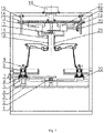
Fig. 1 is a front view of a device for automatically removing burrs from a wheel riser; -
Fig. 2 is a left view of the device for automatically removing burrs from the wheel riser; -
Fig. 3 is a top view of the device for automatically removing burrs from the wheel riser; - In which, 1-frame, 2-clamping gear rack structure, 3-support plate, 4-servo motor, 5-lower guide rail, 6-left sliding plate, 7-clamping cylinder, 8-shaft, 9-clamping wheel, 10-left burr tool, 11-ranging sensor, 12-feed gear rack structure, 13-left sliding block, 14-movable support plate, 15-guide pillar, 16-feed cylinder, 17-right sliding block, 18-upper guide rail, 19-cylinder support plate, 20-distance adjusting cylinder, 21-right burr tool, 22-right sliding plate.
- The details and working conditions of the specific device proposed by the present invention will be described below in combination with the accompanying drawings.
- A device for automatically removing burrs from a wheel riser is composed of a frame 1, a clamping gear rack structure 2, a support plate 3, a servo motor 4, lower guide rails 5, a left
sliding plate 6, a clamping cylinder 7, a shaft 8, aclamping wheel 9, aleft burr tool 10, rangingsensors 11, a feed gear rack structure 12, a left slidingblock 13, amovable support plate 14,guide pillars 15, afeed cylinder 16, a right slidingblock 17,upper guide rails 18, acylinder support plate 19, adistance adjusting cylinder 20, aright burr tool 21 and a rightsliding plate 22. - The support plate 3 is fixed on the frame 1, the lower guide rails 5 are mounted on the support plate 3, the left
sliding plate 6 is connected with the rightsliding plate 22 by the clamping gear rack structure 2, the servo motor 4 is connected with theclamping wheel 9 through the shaft 8, the clamping cylinder 7 is connected with the leftsliding plate 6, and the servo motor 4 is mounted on the leftsliding plate 6. When the clamping cylinder 7 drives the left slidingplate 6 to move, the right slidingplate 22 moves synchronously with the left slidingplate 6 under the action of the clamping gear rack structure 2 to control theclamping wheel 9 to center and clamp a wheel. The servo motor 4 controls the rotation of theclamping wheel 9, so that the wheel can rotate while being clamped. - Two
guide pillars 15 are bilaterally symmetrically mounted at the upper part of the frame 1, thefeed cylinder 16 is mounted in the upper center of the frame 1, the output end of thefeed cylinder 16 is connected to themovable support plate 14, theupper guide rails 18 are mounted on themovable support plate 14, the left slidingblock 13 is connected with the right slidingblock 17 by the feed gear rack structure 12, theleft burr tool 10 and theright burr tool 21 are respectively fixed on the left slidingblock 13 and the right slidingblock 17, a rangingsensor 11 is respectively mounted on theleft burr tool 10 and theright burr tool 21, thecylinder support plate 19 is fixed on themovable support plate 14, thedistance adjusting cylinder 20 is mounted on thecylinder support plate 19, and the output end of thedistance adjusting cylinder 20 is connected to the right slidingblock 17. When thedistance adjusting cylinder 20 drives the right slidingblock 17 to move, the left slidingblock 13 and the right slidingblock 17 move synchronously under the action of the feed gear rack structure 12, so that theleft burr tool 10 and theright burr tool 21 move synchronously to adjust the distance between the tools according to the diameter of a cap slot. Under the guidance of theguide pillars 15, thefeed cylinder 16 controls themovable support plate 14 to move up and down so as to realize feeding and resetting of the burr tools. The two rangingsensors 11 measure the distances from the tools to the burrs of the riser, an average value is taken and then a signal is fed back to thefeed cylinder 16 to determine the exact descending distances of the burr tools, and the burrs are accurately removed by cooperation of the rotating wheel and the linearly fed tools. - During operation, firstly, the distance between the tools is adjusted according to the diameter of a cap slot of a wheel produced on an automatic line, that is, the distance adjusting cylinder is started, and the distance between the left burr tool and the right burr tool can be adjusted under the action of the gear rack structure, so that the distance between the tools is matched with the diameter of the cap slot of the produced wheel; when the wheel reaches a position below the device along a roller bed, the roller bed stops rotating, and then the clamping cylinder is started to center and clamp the wheel; next, the ranging sensors measure the distances from the tools to the edge of the riser and feed the measurement results back to the feed cylinder, the feed cylinder accurately descends for feeding, at the same time, the servo motor drives the clamping wheel to rotate so as to drive the hub to rotate, and the burr tools remove burrs when contacting the rotating wheel; and finally, the burr tools ascend to reset, the clamping wheel stops rotating and releases the hub, the roller bed rotates away the hub from which the burrs have been removed, and receives next hub to be deburred, and so on.
- The present invention can meet the requirement for automatically removing burrs from a riser in wheel line operation, and greatly improves the removal effect compared with a manual burr removal method. The device can, according to the deformation of the riser of each wheel, correspondingly adjust the feed distance of the tools, thereby greatly improving the consistency of products. By adopting the device to remove burrs, the fillets at the edge of the riser are smooth and uniform, which solves the problem of inconsistency of the riser after the burrs are removed from the wheel.
Claims (2)
- A device for automatically removing burrs from a wheel riser, comprising a frame (1), a support plate (3), lower guide rails (5), a left sliding plate (6), a right sliding plate (22), a servo motor (4), a shaft (8), a clamping cylinder (7), a left burr tool (10), a right burr tool (21), a feed gear rack structure (12), a left sliding block (13), a right sliding block (17), two guide pillars (15), a feed cylinder (16), a cylinder support plate (19), a movable support plate (14), a distance adjusting cylinder (20), whereinthe support plate (3) is fixed on the frame (1), the lower guide rails (5) are mounted on the support plate (3), the clamping cylinder (7) is connected with the left sliding plate (6), the left sliding block (13) is connected with the right sliding block (17) by the feed gear rack structure (12), the left burr tool (10) and the right burr tool (21) are respectively fixed on the left sliding block (13) and the right sliding block (17),characterized in that the device further comprises a clamping wheel (9), a clamping gear rack structure (2), upper guide rails (18), ranging sensors (11), the left sliding plate (6) being connected with the right sliding plate (22) by the clamping gear rack structure (2), the servo motor (4) is connected with the clamping wheel (9) through the shaft (8),when the clamping cylinder (7) drives the left sliding plate (6) to move, the right sliding plate (22) moves synchronously with the left sliding plate (6) under the action of the clamping gear rack structure (2) to control the clamping wheel (9) to center and clamp a wheel, wherein the servo motor (4) is mounted on the left sliding plate (6) and controls the rotation of the clamping wheel (9), so that the wheel can rotate while being clamped,wherein the two guide pillars (15) are bilaterally symmetrically mounted at the upper part of the frame (1), the feed cylinder (16) is mounted in the upper center of the frame (1), the output end of the feed cylinder (16) is connected to the movable support plate (14), wherein the upper guide rails (18) are mounted on the movable support plate (14), the ranging sensors (11) are respectively mounted on the left burr tool (10) and the right burr tool (21),the cylinder support plate (19) is fixed on the movable support plate (14), wherein the distance adjusting cylinder (20) is mounted on the cylinder support plate (19), and the output end of the distance adjusting cylinder (20) is connected to the right sliding block (17).
- The device for automatically removing burrs from a wheel riser according to claim 1, wherein when the distance adjusting cylinder (20) drives the right sliding block (17) to move, the left sliding block (13) and the right sliding block (17) move synchronously under the action of the feed gear rack structure (12), so that the left burr tool (10) and the right burr tool (21) move synchronously to adjust the distance between the tools according to the diameter of a cap slot, under the guidance of the guide pillars (15), the feed cylinder (16) controls the movable support plate (14) to move up and down so as to realize feeding and resetting of the burr tools, the two ranging sensors (11) measure the distances from the tools to the burrs of the riser, an average value is taken and then a signal is fed back to the feed cylinder (16) to determine the exact descending distances of the burr tools, and the burrs are accurately removed by cooperation of the rotating wheel and the linearly fed tools.
Applications Claiming Priority (1)
| Application Number | Priority Date | Filing Date | Title |
|---|---|---|---|
| CN201711049081.4A CN107717126A (en) | 2017-10-31 | 2017-10-31 | A kind of device for being used to remove aluminum-alloy wheel rising head burr |
Publications (2)
| Publication Number | Publication Date |
|---|---|
| EP3476506A1 EP3476506A1 (en) | 2019-05-01 |
| EP3476506B1 true EP3476506B1 (en) | 2022-12-07 |
Family
ID=61202036
Family Applications (1)
| Application Number | Title | Priority Date | Filing Date |
|---|---|---|---|
| EP18203000.7A Active EP3476506B1 (en) | 2017-10-31 | 2018-10-26 | Device for automatically removing burrs from a wheel hub section |
Country Status (4)
| Country | Link |
|---|---|
| US (1) | US11213925B2 (en) |
| EP (1) | EP3476506B1 (en) |
| CN (1) | CN107717126A (en) |
| MA (1) | MA44575B1 (en) |
Families Citing this family (20)
| Publication number | Priority date | Publication date | Assignee | Title |
|---|---|---|---|---|
| CN108296898A (en) * | 2018-04-16 | 2018-07-20 | 马鞍山市增润机械制造有限公司 | A kind of jade bracelet grinding apparatus safety aid and its control method |
| CN108608609A (en) * | 2018-04-19 | 2018-10-02 | 王海彬 | A kind of novel rubber product production device for deburring |
| CN109116114A (en) * | 2018-10-09 | 2019-01-01 | 江苏英锐半导体有限公司 | A kind of resistivity detecting device for wafer flow |
| CN110076651B (en) * | 2019-05-18 | 2024-07-12 | 浙江科泰汽车部件有限公司 | Automobile screw production equipment for deburring |
| CN110181123A (en) * | 2019-06-12 | 2019-08-30 | 赣州群星机械有限公司 | Remove tooth set milling inside groove burr device |
| CN110421452B (en) * | 2019-08-21 | 2021-05-04 | 肇庆市建泯装饰材料有限公司 | Complicated curved surface plank grinding device |
| CN112220295A (en) * | 2019-11-20 | 2021-01-15 | 绍兴市载沣智能科技有限公司 | Display equipment for ensuring stability of electronic product and display method thereof |
| CN112192374B (en) * | 2020-09-18 | 2021-12-07 | 河南省儿童医院郑州儿童医院 | A grinding device for machining of mechanical seal spare |
| CN112428496B (en) * | 2020-10-29 | 2025-04-25 | 济南伦渠数控机电有限公司 | A new corner cleaning method and structure for cleaning corner seams of plastic doors and windows |
| CN112428497B (en) * | 2020-10-29 | 2024-06-14 | 济南伦渠数控机电有限公司 | Corner cleaning method and structure for simultaneous cleaning of the four corners of plastic doors and windows |
| CN112453369B (en) * | 2020-11-25 | 2021-11-23 | 烟台万隆真空冶金股份有限公司 | Automatic machining system for casting head of casting part |
| CN112548828A (en) * | 2020-12-10 | 2021-03-26 | 芜湖恩之伟汽车零部件有限公司 | Automobile wheel hub burnishing device |
| CN112605783B (en) * | 2020-12-30 | 2022-06-24 | 青岛捷泰塑业新材料有限公司 | Foamed plastic board edging machine |
| CN113092140B (en) * | 2021-05-14 | 2023-01-17 | 烟台大学 | A Two-wheeled Motorcycle Online Angle Test Device |
| CN113857518A (en) * | 2021-09-30 | 2021-12-31 | 轻工业西安机械设计研究院有限公司 | Automobile gear round hole machining machine tool and method |
| CN114454001B (en) * | 2022-02-28 | 2023-10-20 | 苏州勇讯精密机械有限公司 | A burr grinding device and grinding method for hydraulic valve block hole processing |
| CN115106783B (en) * | 2022-07-11 | 2023-09-22 | 江苏苏美达铝业有限公司 | High-efficient quick wheel hub cuts and emits device |
| CN116659389B (en) * | 2023-05-17 | 2024-01-30 | 儒拉玛特自动化技术(合肥)有限公司 | A fully automatic pass-and-stop gauge detection device |
| CN119217264B (en) * | 2024-09-23 | 2025-03-14 | 山东晨华汽车部件有限公司 | Wheel spoke bolt hole measurement device that polishes |
| CN119057611B (en) * | 2024-11-06 | 2025-04-11 | 江苏弗林特机电科技有限公司 | A burr cleaning device for cylinder inner wall used for electric hammer cylinder processing |
Family Cites Families (13)
| Publication number | Priority date | Publication date | Assignee | Title |
|---|---|---|---|---|
| US5161281A (en) * | 1990-08-14 | 1992-11-10 | Hanen Harry I | Wheel rim cleaning apparatus |
| JP4320665B2 (en) * | 2005-08-09 | 2009-08-26 | 株式会社ワーク | 2-piece wheel plating remover |
| JP4079180B2 (en) * | 2005-08-22 | 2008-04-23 | 株式会社ワーク | 3 piece wheel plating remover |
| JP4107335B2 (en) * | 2005-09-01 | 2008-06-25 | 株式会社ワーク | Wheel manufacturing method |
| US9017141B2 (en) * | 2013-01-04 | 2015-04-28 | White Drive Products, Inc. | Deburring machine and method for deburring |
| CN204240970U (en) * | 2014-12-13 | 2015-04-01 | 中信戴卡股份有限公司 | A kind of wheel diameters pick-up unit |
| TWM515963U (en) * | 2015-08-27 | 2016-01-21 | 發得科技工業股份有限公司 | Rim processing device |
| CN105526870B (en) * | 2016-01-26 | 2017-12-29 | 中信戴卡股份有限公司 | A kind of method for detecting aluminum vehicle wheel strand core wheel depth |
| CN205833111U (en) * | 2016-07-27 | 2016-12-28 | 苏州工业园区雅可集团有限公司 | A kind of high-performance dry-process granulator tablet press mechanism |
| CN106938417A (en) * | 2017-03-20 | 2017-07-11 | 中信戴卡股份有限公司 | A kind of device for being used to remove wheel rim burr automatically |
| CN107283000B (en) * | 2017-07-31 | 2024-01-19 | 中信戴卡股份有限公司 | High-precision device for removing burrs at wheel cap opening |
| CN207326094U (en) * | 2017-10-31 | 2018-05-08 | 中信戴卡股份有限公司 | A kind of device for being used to remove aluminum-alloy wheel riser burr |
| CN108213594A (en) * | 2018-01-24 | 2018-06-29 | 中信戴卡股份有限公司 | A kind of high-precision removes wheel circumference burr device |
-
2017
- 2017-10-31 CN CN201711049081.4A patent/CN107717126A/en active Pending
-
2018
- 2018-10-26 EP EP18203000.7A patent/EP3476506B1/en active Active
- 2018-10-26 US US16/172,120 patent/US11213925B2/en active Active
- 2018-10-26 MA MA44575A patent/MA44575B1/en unknown
Also Published As
| Publication number | Publication date |
|---|---|
| CN107717126A (en) | 2018-02-23 |
| US20190126424A1 (en) | 2019-05-02 |
| MA44575B1 (en) | 2023-01-31 |
| US11213925B2 (en) | 2022-01-04 |
| EP3476506A1 (en) | 2019-05-01 |
Similar Documents
| Publication | Publication Date | Title |
|---|---|---|
| EP3476506A1 (en) | Device for automatically removing burrs from a wheel hub section | |
| EP3431225B1 (en) | Wheel blank positioning end face correction device | |
| EP3520935B1 (en) | Device for removing circumferential burrs of wheel with high precision | |
| US11370077B2 (en) | Device for removing burrs from bolt holes of aluminum alloy wheel | |
| CN210160773U (en) | A kind of automatic centering device for sheet metal cutting for machining | |
| US10730114B2 (en) | Device for trimming positioning end surface of wheel blank | |
| US20190202019A1 (en) | Device for removing tool joint edge burrs of wheel | |
| CN108068093A (en) | A wheel blank outer rim marking device | |
| CN103008935A (en) | Cover sealing welding machine of compressor | |
| CN107414097B (en) | Round corner trimming device for outer wheel rim of vehicle | |
| CN211218046U (en) | Automatic guiding and correcting device for aluminum material belt production line | |
| CN207606824U (en) | A wheel blank outer rim marking device | |
| CN117620927A (en) | An elevator door panel is processed with a clamping and positioning mechanism | |
| CN202944123U (en) | Novel chuck and corresponding engraving machine | |
| CN203600008U (en) | Wheel rim corner position online detection device | |
| CN207188619U (en) | Oiling forcing press | |
| CN105035852A (en) | Automatic upper and lower disc layer winding machine capable of adjusting silk disc width and precisely positioning | |
| CN205011142U (en) | Hypothecium is around machine in automation of adjustable silk dish width, accurate positioning | |
| CN207326094U (en) | A kind of device for being used to remove aluminum-alloy wheel riser burr | |
| CN201900326U (en) | Double-sided sawing machine tool of aluminum alloy members | |
| CN113587875B (en) | Zero point positioning method for length measurement of vertical continuous casting billet | |
| SE436846B (en) | DEVICE FOR THE MANUFACTURE OF CYLINDRICAL NECK BODIES | |
| CN204308330U (en) | A kind of chain digital control gear hobbing machine laser tooth mesh device | |
| CN117020657A (en) | Double-procedure aluminum plate slotting and cutting integrated machine | |
| CN207548377U (en) | A kind of device for aluminum-alloy wheel bolt hole deburring |
Legal Events
| Date | Code | Title | Description |
|---|---|---|---|
| PUAI | Public reference made under article 153(3) epc to a published international application that has entered the european phase |
Free format text: ORIGINAL CODE: 0009012 |
|
| STAA | Information on the status of an ep patent application or granted ep patent |
Free format text: STATUS: REQUEST FOR EXAMINATION WAS MADE |
|
| 17P | Request for examination filed |
Effective date: 20181026 |
|
| AK | Designated contracting states |
Kind code of ref document: A1 Designated state(s): AL AT BE BG CH CY CZ DE DK EE ES FI FR GB GR HR HU IE IS IT LI LT LU LV MC MK MT NL NO PL PT RO RS SE SI SK SM TR |
|
| AX | Request for extension of the european patent |
Extension state: BA ME |
|
| RIC1 | Information provided on ipc code assigned before grant |
Ipc: B24B 9/04 20060101ALI20220406BHEP Ipc: B22D 31/00 20060101ALI20220406BHEP Ipc: B23B 5/28 20060101AFI20220406BHEP |
|
| GRAP | Despatch of communication of intention to grant a patent |
Free format text: ORIGINAL CODE: EPIDOSNIGR1 |
|
| STAA | Information on the status of an ep patent application or granted ep patent |
Free format text: STATUS: GRANT OF PATENT IS INTENDED |
|
| INTG | Intention to grant announced |
Effective date: 20220601 |
|
| GRAS | Grant fee paid |
Free format text: ORIGINAL CODE: EPIDOSNIGR3 |
|
| GRAA | (expected) grant |
Free format text: ORIGINAL CODE: 0009210 |
|
| STAA | Information on the status of an ep patent application or granted ep patent |
Free format text: STATUS: THE PATENT HAS BEEN GRANTED |
|
| AK | Designated contracting states |
Kind code of ref document: B1 Designated state(s): AL AT BE BG CH CY CZ DE DK EE ES FI FR GB GR HR HU IE IS IT LI LT LU LV MC MK MT NL NO PL PT RO RS SE SI SK SM TR |
|
| REG | Reference to a national code |
Ref country code: GB Ref legal event code: FG4D |
|
| REG | Reference to a national code |
Ref country code: CH Ref legal event code: EP Ref country code: AT Ref legal event code: REF Ref document number: 1536000 Country of ref document: AT Kind code of ref document: T Effective date: 20221215 |
|
| REG | Reference to a national code |
Ref country code: DE Ref legal event code: R096 Ref document number: 602018043918 Country of ref document: DE |
|
| REG | Reference to a national code |
Ref country code: IE Ref legal event code: FG4D |
|
| REG | Reference to a national code |
Ref country code: MA Ref legal event code: VAGR Ref document number: 44575 Country of ref document: MA Kind code of ref document: B1 |
|
| REG | Reference to a national code |
Ref country code: LT Ref legal event code: MG9D |
|
| REG | Reference to a national code |
Ref country code: NL Ref legal event code: MP Effective date: 20221207 |
|
| PG25 | Lapsed in a contracting state [announced via postgrant information from national office to epo] |
Ref country code: SE Free format text: LAPSE BECAUSE OF FAILURE TO SUBMIT A TRANSLATION OF THE DESCRIPTION OR TO PAY THE FEE WITHIN THE PRESCRIBED TIME-LIMIT Effective date: 20221207 Ref country code: NO Free format text: LAPSE BECAUSE OF FAILURE TO SUBMIT A TRANSLATION OF THE DESCRIPTION OR TO PAY THE FEE WITHIN THE PRESCRIBED TIME-LIMIT Effective date: 20230307 Ref country code: LT Free format text: LAPSE BECAUSE OF FAILURE TO SUBMIT A TRANSLATION OF THE DESCRIPTION OR TO PAY THE FEE WITHIN THE PRESCRIBED TIME-LIMIT Effective date: 20221207 Ref country code: FI Free format text: LAPSE BECAUSE OF FAILURE TO SUBMIT A TRANSLATION OF THE DESCRIPTION OR TO PAY THE FEE WITHIN THE PRESCRIBED TIME-LIMIT Effective date: 20221207 Ref country code: ES Free format text: LAPSE BECAUSE OF FAILURE TO SUBMIT A TRANSLATION OF THE DESCRIPTION OR TO PAY THE FEE WITHIN THE PRESCRIBED TIME-LIMIT Effective date: 20221207 |
|
| REG | Reference to a national code |
Ref country code: AT Ref legal event code: MK05 Ref document number: 1536000 Country of ref document: AT Kind code of ref document: T Effective date: 20221207 |
|
| PG25 | Lapsed in a contracting state [announced via postgrant information from national office to epo] |
Ref country code: RS Free format text: LAPSE BECAUSE OF FAILURE TO SUBMIT A TRANSLATION OF THE DESCRIPTION OR TO PAY THE FEE WITHIN THE PRESCRIBED TIME-LIMIT Effective date: 20221207 Ref country code: PL Free format text: LAPSE BECAUSE OF FAILURE TO SUBMIT A TRANSLATION OF THE DESCRIPTION OR TO PAY THE FEE WITHIN THE PRESCRIBED TIME-LIMIT Effective date: 20221207 Ref country code: LV Free format text: LAPSE BECAUSE OF FAILURE TO SUBMIT A TRANSLATION OF THE DESCRIPTION OR TO PAY THE FEE WITHIN THE PRESCRIBED TIME-LIMIT Effective date: 20221207 Ref country code: HR Free format text: LAPSE BECAUSE OF FAILURE TO SUBMIT A TRANSLATION OF THE DESCRIPTION OR TO PAY THE FEE WITHIN THE PRESCRIBED TIME-LIMIT Effective date: 20221207 Ref country code: GR Free format text: LAPSE BECAUSE OF FAILURE TO SUBMIT A TRANSLATION OF THE DESCRIPTION OR TO PAY THE FEE WITHIN THE PRESCRIBED TIME-LIMIT Effective date: 20230308 |
|
| PG25 | Lapsed in a contracting state [announced via postgrant information from national office to epo] |
Ref country code: NL Free format text: LAPSE BECAUSE OF FAILURE TO SUBMIT A TRANSLATION OF THE DESCRIPTION OR TO PAY THE FEE WITHIN THE PRESCRIBED TIME-LIMIT Effective date: 20221207 |
|
| PG25 | Lapsed in a contracting state [announced via postgrant information from national office to epo] |
Ref country code: SM Free format text: LAPSE BECAUSE OF FAILURE TO SUBMIT A TRANSLATION OF THE DESCRIPTION OR TO PAY THE FEE WITHIN THE PRESCRIBED TIME-LIMIT Effective date: 20221207 Ref country code: RO Free format text: LAPSE BECAUSE OF FAILURE TO SUBMIT A TRANSLATION OF THE DESCRIPTION OR TO PAY THE FEE WITHIN THE PRESCRIBED TIME-LIMIT Effective date: 20221207 Ref country code: PT Free format text: LAPSE BECAUSE OF FAILURE TO SUBMIT A TRANSLATION OF THE DESCRIPTION OR TO PAY THE FEE WITHIN THE PRESCRIBED TIME-LIMIT Effective date: 20230410 Ref country code: EE Free format text: LAPSE BECAUSE OF FAILURE TO SUBMIT A TRANSLATION OF THE DESCRIPTION OR TO PAY THE FEE WITHIN THE PRESCRIBED TIME-LIMIT Effective date: 20221207 Ref country code: CZ Free format text: LAPSE BECAUSE OF FAILURE TO SUBMIT A TRANSLATION OF THE DESCRIPTION OR TO PAY THE FEE WITHIN THE PRESCRIBED TIME-LIMIT Effective date: 20221207 Ref country code: AT Free format text: LAPSE BECAUSE OF FAILURE TO SUBMIT A TRANSLATION OF THE DESCRIPTION OR TO PAY THE FEE WITHIN THE PRESCRIBED TIME-LIMIT Effective date: 20221207 |
|
| PG25 | Lapsed in a contracting state [announced via postgrant information from national office to epo] |
Ref country code: SK Free format text: LAPSE BECAUSE OF FAILURE TO SUBMIT A TRANSLATION OF THE DESCRIPTION OR TO PAY THE FEE WITHIN THE PRESCRIBED TIME-LIMIT Effective date: 20221207 Ref country code: IS Free format text: LAPSE BECAUSE OF FAILURE TO SUBMIT A TRANSLATION OF THE DESCRIPTION OR TO PAY THE FEE WITHIN THE PRESCRIBED TIME-LIMIT Effective date: 20230407 Ref country code: AL Free format text: LAPSE BECAUSE OF FAILURE TO SUBMIT A TRANSLATION OF THE DESCRIPTION OR TO PAY THE FEE WITHIN THE PRESCRIBED TIME-LIMIT Effective date: 20221207 |
|
| REG | Reference to a national code |
Ref country code: DE Ref legal event code: R097 Ref document number: 602018043918 Country of ref document: DE |
|
| PLBE | No opposition filed within time limit |
Free format text: ORIGINAL CODE: 0009261 |
|
| STAA | Information on the status of an ep patent application or granted ep patent |
Free format text: STATUS: NO OPPOSITION FILED WITHIN TIME LIMIT |
|
| PG25 | Lapsed in a contracting state [announced via postgrant information from national office to epo] |
Ref country code: DK Free format text: LAPSE BECAUSE OF FAILURE TO SUBMIT A TRANSLATION OF THE DESCRIPTION OR TO PAY THE FEE WITHIN THE PRESCRIBED TIME-LIMIT Effective date: 20221207 |
|
| 26N | No opposition filed |
Effective date: 20230908 |
|
| PG25 | Lapsed in a contracting state [announced via postgrant information from national office to epo] |
Ref country code: SI Free format text: LAPSE BECAUSE OF FAILURE TO SUBMIT A TRANSLATION OF THE DESCRIPTION OR TO PAY THE FEE WITHIN THE PRESCRIBED TIME-LIMIT Effective date: 20221207 |
|
| PG25 | Lapsed in a contracting state [announced via postgrant information from national office to epo] |
Ref country code: IT Free format text: LAPSE BECAUSE OF FAILURE TO SUBMIT A TRANSLATION OF THE DESCRIPTION OR TO PAY THE FEE WITHIN THE PRESCRIBED TIME-LIMIT Effective date: 20221207 Ref country code: MC Free format text: LAPSE BECAUSE OF FAILURE TO SUBMIT A TRANSLATION OF THE DESCRIPTION OR TO PAY THE FEE WITHIN THE PRESCRIBED TIME-LIMIT Effective date: 20221207 |
|
| REG | Reference to a national code |
Ref country code: CH Ref legal event code: PL |
|
| REG | Reference to a national code |
Ref country code: BE Ref legal event code: MM Effective date: 20231031 |
|
| PG25 | Lapsed in a contracting state [announced via postgrant information from national office to epo] |
Ref country code: LU Free format text: LAPSE BECAUSE OF NON-PAYMENT OF DUE FEES Effective date: 20231026 |
|
| GBPC | Gb: european patent ceased through non-payment of renewal fee |
Effective date: 20231026 |
|
| PG25 | Lapsed in a contracting state [announced via postgrant information from national office to epo] |
Ref country code: LU Free format text: LAPSE BECAUSE OF NON-PAYMENT OF DUE FEES Effective date: 20231026 |
|
| PG25 | Lapsed in a contracting state [announced via postgrant information from national office to epo] |
Ref country code: GB Free format text: LAPSE BECAUSE OF NON-PAYMENT OF DUE FEES Effective date: 20231026 |
|
| PG25 | Lapsed in a contracting state [announced via postgrant information from national office to epo] |
Ref country code: CH Free format text: LAPSE BECAUSE OF NON-PAYMENT OF DUE FEES Effective date: 20231031 |
|
| PG25 | Lapsed in a contracting state [announced via postgrant information from national office to epo] |
Ref country code: GB Free format text: LAPSE BECAUSE OF NON-PAYMENT OF DUE FEES Effective date: 20231026 Ref country code: CH Free format text: LAPSE BECAUSE OF NON-PAYMENT OF DUE FEES Effective date: 20231031 |
|
| PG25 | Lapsed in a contracting state [announced via postgrant information from national office to epo] |
Ref country code: BE Free format text: LAPSE BECAUSE OF NON-PAYMENT OF DUE FEES Effective date: 20231031 |
|
| PG25 | Lapsed in a contracting state [announced via postgrant information from national office to epo] |
Ref country code: IE Free format text: LAPSE BECAUSE OF NON-PAYMENT OF DUE FEES Effective date: 20231026 |
|
| PG25 | Lapsed in a contracting state [announced via postgrant information from national office to epo] |
Ref country code: IE Free format text: LAPSE BECAUSE OF NON-PAYMENT OF DUE FEES Effective date: 20231026 |
|
| PG25 | Lapsed in a contracting state [announced via postgrant information from national office to epo] |
Ref country code: BG Free format text: LAPSE BECAUSE OF FAILURE TO SUBMIT A TRANSLATION OF THE DESCRIPTION OR TO PAY THE FEE WITHIN THE PRESCRIBED TIME-LIMIT Effective date: 20221207 |
|
| PG25 | Lapsed in a contracting state [announced via postgrant information from national office to epo] |
Ref country code: BG Free format text: LAPSE BECAUSE OF FAILURE TO SUBMIT A TRANSLATION OF THE DESCRIPTION OR TO PAY THE FEE WITHIN THE PRESCRIBED TIME-LIMIT Effective date: 20221207 |
|
| PG25 | Lapsed in a contracting state [announced via postgrant information from national office to epo] |
Ref country code: CY Free format text: LAPSE BECAUSE OF FAILURE TO SUBMIT A TRANSLATION OF THE DESCRIPTION OR TO PAY THE FEE WITHIN THE PRESCRIBED TIME-LIMIT; INVALID AB INITIO Effective date: 20181026 |
|
| PG25 | Lapsed in a contracting state [announced via postgrant information from national office to epo] |
Ref country code: HU Free format text: LAPSE BECAUSE OF FAILURE TO SUBMIT A TRANSLATION OF THE DESCRIPTION OR TO PAY THE FEE WITHIN THE PRESCRIBED TIME-LIMIT; INVALID AB INITIO Effective date: 20181026 |
|
| VS25 | Lapsed in a validation state [announced via postgrant information from nat. office to epo] |
Ref country code: MA Free format text: LAPSE BECAUSE OF NON-PAYMENT OF DUE FEES Effective date: 20241027 |
|
| VSFP | Annual fee paid to validation state [announced via postgrant information from national office to epo] |
Ref country code: MA Payment date: 20231003 Year of fee payment: 6 |
|
| PG25 | Lapsed in a contracting state [announced via postgrant information from national office to epo] |
Ref country code: TR Free format text: LAPSE BECAUSE OF FAILURE TO SUBMIT A TRANSLATION OF THE DESCRIPTION OR TO PAY THE FEE WITHIN THE PRESCRIBED TIME-LIMIT Effective date: 20221207 |
|
| PGFP | Annual fee paid to national office [announced via postgrant information from national office to epo] |
Ref country code: DE Payment date: 20251015 Year of fee payment: 8 |
|
| PGFP | Annual fee paid to national office [announced via postgrant information from national office to epo] |
Ref country code: FR Payment date: 20251027 Year of fee payment: 8 |