EP3476285A1 - System and method for health condition monitoring - Google Patents
System and method for health condition monitoring Download PDFInfo
- Publication number
- EP3476285A1 EP3476285A1 EP18200030.7A EP18200030A EP3476285A1 EP 3476285 A1 EP3476285 A1 EP 3476285A1 EP 18200030 A EP18200030 A EP 18200030A EP 3476285 A1 EP3476285 A1 EP 3476285A1
- Authority
- EP
- European Patent Office
- Prior art keywords
- ecg
- health condition
- condition monitoring
- signal
- wearable device
- Prior art date
- Legal status (The legal status is an assumption and is not a legal conclusion. Google has not performed a legal analysis and makes no representation as to the accuracy of the status listed.)
- Withdrawn
Links
- 0 CC1C(*)CCC1 Chemical compound CC1C(*)CCC1 0.000 description 1
Images









Classifications
-
- A—HUMAN NECESSITIES
- A61—MEDICAL OR VETERINARY SCIENCE; HYGIENE
- A61B—DIAGNOSIS; SURGERY; IDENTIFICATION
- A61B5/00—Measuring for diagnostic purposes; Identification of persons
- A61B5/68—Arrangements of detecting, measuring or recording means, e.g. sensors, in relation to patient
- A61B5/6801—Arrangements of detecting, measuring or recording means, e.g. sensors, in relation to patient specially adapted to be attached to or worn on the body surface
- A61B5/6802—Sensor mounted on worn items
- A61B5/6804—Garments; Clothes
- A61B5/6805—Vests, e.g. shirts or gowns
-
- A—HUMAN NECESSITIES
- A61—MEDICAL OR VETERINARY SCIENCE; HYGIENE
- A61B—DIAGNOSIS; SURGERY; IDENTIFICATION
- A61B5/00—Measuring for diagnostic purposes; Identification of persons
- A61B5/0002—Remote monitoring of patients using telemetry, e.g. transmission of vital signals via a communication network
- A61B5/0015—Remote monitoring of patients using telemetry, e.g. transmission of vital signals via a communication network characterised by features of the telemetry system
- A61B5/002—Monitoring the patient using a local or closed circuit, e.g. in a room or building
-
- A—HUMAN NECESSITIES
- A61—MEDICAL OR VETERINARY SCIENCE; HYGIENE
- A61B—DIAGNOSIS; SURGERY; IDENTIFICATION
- A61B5/00—Measuring for diagnostic purposes; Identification of persons
- A61B5/02—Detecting, measuring or recording for evaluating the cardiovascular system, e.g. pulse, heart rate, blood pressure or blood flow
- A61B5/0205—Simultaneously evaluating both cardiovascular conditions and different types of body conditions, e.g. heart and respiratory condition
-
- A—HUMAN NECESSITIES
- A61—MEDICAL OR VETERINARY SCIENCE; HYGIENE
- A61B—DIAGNOSIS; SURGERY; IDENTIFICATION
- A61B5/00—Measuring for diagnostic purposes; Identification of persons
- A61B5/08—Measuring devices for evaluating the respiratory organs
- A61B5/0816—Measuring devices for examining respiratory frequency
-
- A—HUMAN NECESSITIES
- A61—MEDICAL OR VETERINARY SCIENCE; HYGIENE
- A61B—DIAGNOSIS; SURGERY; IDENTIFICATION
- A61B5/00—Measuring for diagnostic purposes; Identification of persons
- A61B5/24—Detecting, measuring or recording bioelectric or biomagnetic signals of the body or parts thereof
- A61B5/316—Modalities, i.e. specific diagnostic methods
- A61B5/318—Heart-related electrical modalities, e.g. electrocardiography [ECG]
- A61B5/346—Analysis of electrocardiograms
- A61B5/349—Detecting specific parameters of the electrocardiograph cycle
-
- A—HUMAN NECESSITIES
- A61—MEDICAL OR VETERINARY SCIENCE; HYGIENE
- A61B—DIAGNOSIS; SURGERY; IDENTIFICATION
- A61B5/00—Measuring for diagnostic purposes; Identification of persons
- A61B5/24—Detecting, measuring or recording bioelectric or biomagnetic signals of the body or parts thereof
- A61B5/316—Modalities, i.e. specific diagnostic methods
- A61B5/318—Heart-related electrical modalities, e.g. electrocardiography [ECG]
- A61B5/346—Analysis of electrocardiograms
- A61B5/349—Detecting specific parameters of the electrocardiograph cycle
- A61B5/35—Detecting specific parameters of the electrocardiograph cycle by template matching
-
- A—HUMAN NECESSITIES
- A61—MEDICAL OR VETERINARY SCIENCE; HYGIENE
- A61B—DIAGNOSIS; SURGERY; IDENTIFICATION
- A61B5/00—Measuring for diagnostic purposes; Identification of persons
- A61B5/72—Signal processing specially adapted for physiological signals or for diagnostic purposes
- A61B5/7203—Signal processing specially adapted for physiological signals or for diagnostic purposes for noise prevention, reduction or removal
-
- A—HUMAN NECESSITIES
- A61—MEDICAL OR VETERINARY SCIENCE; HYGIENE
- A61B—DIAGNOSIS; SURGERY; IDENTIFICATION
- A61B7/00—Instruments for auscultation
- A61B7/003—Detecting lung or respiration noise
-
- A—HUMAN NECESSITIES
- A61—MEDICAL OR VETERINARY SCIENCE; HYGIENE
- A61B—DIAGNOSIS; SURGERY; IDENTIFICATION
- A61B2562/00—Details of sensors; Constructional details of sensor housings or probes; Accessories for sensors
- A61B2562/02—Details of sensors specially adapted for in-vivo measurements
- A61B2562/0209—Special features of electrodes classified in A61B5/24, A61B5/25, A61B5/283, A61B5/291, A61B5/296, A61B5/053
-
- A—HUMAN NECESSITIES
- A61—MEDICAL OR VETERINARY SCIENCE; HYGIENE
- A61B—DIAGNOSIS; SURGERY; IDENTIFICATION
- A61B2562/00—Details of sensors; Constructional details of sensor housings or probes; Accessories for sensors
- A61B2562/02—Details of sensors specially adapted for in-vivo measurements
- A61B2562/028—Microscale sensors, e.g. electromechanical sensors [MEMS]
-
- A—HUMAN NECESSITIES
- A61—MEDICAL OR VETERINARY SCIENCE; HYGIENE
- A61B—DIAGNOSIS; SURGERY; IDENTIFICATION
- A61B5/00—Measuring for diagnostic purposes; Identification of persons
- A61B5/02—Detecting, measuring or recording for evaluating the cardiovascular system, e.g. pulse, heart rate, blood pressure or blood flow
- A61B5/024—Measuring pulse rate or heart rate
- A61B5/0245—Measuring pulse rate or heart rate by using sensing means generating electric signals, i.e. ECG signals
-
- A—HUMAN NECESSITIES
- A61—MEDICAL OR VETERINARY SCIENCE; HYGIENE
- A61B—DIAGNOSIS; SURGERY; IDENTIFICATION
- A61B5/00—Measuring for diagnostic purposes; Identification of persons
- A61B5/72—Signal processing specially adapted for physiological signals or for diagnostic purposes
- A61B5/7235—Details of waveform analysis
- A61B5/7253—Details of waveform analysis characterised by using transforms
- A61B5/7257—Details of waveform analysis characterised by using transforms using Fourier transforms
-
- A—HUMAN NECESSITIES
- A61—MEDICAL OR VETERINARY SCIENCE; HYGIENE
- A61B—DIAGNOSIS; SURGERY; IDENTIFICATION
- A61B5/00—Measuring for diagnostic purposes; Identification of persons
- A61B5/72—Signal processing specially adapted for physiological signals or for diagnostic purposes
- A61B5/7271—Specific aspects of physiological measurement analysis
- A61B5/7278—Artificial waveform generation or derivation, e.g. synthesizing signals from measured signals
Definitions
- the present invention relates to a system and a method for health condition monitoring, and more particularly to a system and a method for health condition monitoring suitable for long term use.
- An object of the present invention is to provide a system and a method for health condition monitoring which can monitor both the heart and the lung functions of the user at anywhere and over a long duration with comfort.
- a system for health condition monitoring including a wearable device, a portable device and a server.
- the portable device is capable of communicating between the wearable device and the server.
- the system for health condition monitoring further includes a non-contact ECG (electrocardiography) acquisition module, a non-contact audio acquisition module, a first signal processing and analysis module and a second signal processing and analysis module.
- the non-contact ECG acquisition module is embedded in the wearable device for capturing ECG signals from a user wearing the wearable device.
- the non-contact audio acquisition module is embedded in the wearable device for capturing a respiratory sound signal and a heart sound signal from the user wearing the wearable device.
- the first signal processing and analysis module is embedded in the wearable device and connected with the non-contact ECG acquisition module and the non-contact audio acquisition module.
- the first signal processing and analysis module is used for receiving and processing the ECG signals, the respiratory sound signal and the heart sound signal from the non-contact ECG acquisition module and the non-contact audio acquisition module.
- QRS detection, HR (heart rate) calculation and ECG derived RR (respiratory rate) determination are performed in the first signal processing and analysis module.
- the second signal processing and analysis module is provided on the server for receiving and processing the ECG signals, the respiratory sound signal and the heart sound signal uploaded by the portable device.
- heart sound localization, heart sound cancellation, respiratory sound restoration, and sound based RR determination are performed in the second signal processing and analysis module, so as to obtain information for health condition monitoring.
- a method for health condition monitoring includes steps of: (a) providing a wearable device, a portable device and a server, the wearable device comprising an embedded non-contact ECG acquisition module, an embedded non-contact audio acquisition module and an embedded first signal processing and analysis module, the portable device being capable of communicating between the wearable device and the server, the server comprising a second signal processing and analysis module; (b) capturing ECG signals by the non-contact ECG acquisition module and capturing a respiratory sound signal and a heart sound signal by the non-contact audio acquisition module from the user wearing the wearable device; (c) processing the ECG signals, the respiratory sound signal and the heart sound signal by the first signal processing and analysis module to perform QRS detection, HR (heart rate) calculation and ECG derived RR (respiratory rate) determination; and (d) processing the ECG signals, the respiratory sound signal and the heart sound signal by the second signal processing and analysis module to perform heart sound localization, heart sound cancellation, respiratory sound restoration,
- FIG. 1 is a diagram illustrating a system for health condition monitoring according to an embodiment of the present invention.
- the system 1 for health condition monitoring includes a wearable device 20, a portable device 30 and a server 40.
- the wearable device 20 When the wearable device 20 is worn by a user, the ECG (electrocardiography), the heart sound and the respiratory sound of the user can be acquired.
- the wearable device 20 can communicate with the portable device 30 for data transmission.
- the data can be further uploaded to the server 40 through the internet web services.
- the doctors, caretakers and family members of the user can retrieve data or be informed of situation where the user is in need of care or emergency medical treatments.
- the wearable device 20 is a wearable vest and the portable device 30 is a smart phone or a tablet.
- FIG. 2 is a diagram illustrating a system for health condition monitoring according to another embodiment of the present invention.
- the system 1 may include plural wearable devices 20A, 20B and plural portable devices 30A, 30B.
- the plural wearable devices 20A may communicate with the same portable device 30A, and the plural wearable devices 20B may communicate with the same portable device 30B.
- the plural wearable devices 20A may be worn by family members, so that the health conditions of the family may be monitored on the same portable device 30A.
- the plural wearable devices 20B may be worn by members of another family, sport team or military unit, so as to monitor the health conditions of the members for the same group on the same portable device 30B.
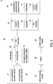
- FIG. 3 is a detailed diagram illustrating the system for health condition monitoring of FIG. 1 .
- the wearable device 20 includes a non-contact ECG acquisition module 21 and a non-contact audio acquisition module 22 to acquire ECG signals and audio signals, respectively, from the user wearing the wearable device 20.
- the non-contact ECG acquisition module 21 and the non-contact audio acquisition module 22 are embedded in the wearable device 20 and do not directly contact the skin of the user. In other words, direct skin contact is not necessary for the system 1 for health condition monitoring of the present invention, so the user can be fully clothed. This not only fulfils the requirement of hygiene purpose but also makes the wearer feel comfortable to improve the compliance of long term use.
- the non-contact ECG acquisition module 21 includes three or more non-contact ECG sensors.
- FIG. 4 is a diagram illustrating the positions of the three non-contact ECG sensors on a human body while wearing the wearable device. When the user is wearing the wearable device 20, the three non-contact ECG sensors will be placed at the positions shown as grey circles in FIG. 4 , which are at the top of the manubrium, the left side of the ninth rib, and the right side of the ninth rib.
- the ECG signals captured from the non-contact ECG sensors located at the top of the manubrium vs. the left side of the ninth rib have similar waveform as the traditional ECG.
- the ECG signals captured from the non-contact ECG sensors located at the left side of the ninth rib vs. the right side of the ninth rib are interfered less by muscle movement, and are thus chosen for ECG signal records during exercises.
- the non-contact ECG acquisition module 21 is used for capturing ECG signals from the user wearing the wearable device 20 through the non-contact ECG sensors.
- FIG. 5 is a circuit diagram illustrating the non-contact ECG acquisition module according to an embodiment of the present invention.
- the non-contact ECG acquisition module 21 includes three non-contact ECG sensors 211 based on capacitance, two differential amplifying circuits 212 and two power line filters 213.
- the three non-contact ECG sensors 211 capture the ECG signals, and then the ECG signals are pre-processed by the non-contact ECG acquisition module 21.
- a pair of non-contact ECG sensors 211 will provide one differential ECG signal.
- the ECG signals from paired non-contact ECG sensors 211 are differentiated by the differential amplifying circuit 212 and then filtered by the power line filter 213. Accordingly, two sets of differential ECG signals are acquired from the three non-contact ECG sensors 211 in the wearable device 20.
- One set of differential non-contact ECG signal provides an ECG signal that emulates 3-leads ECG
- another set of differential non-contact ECG signal provides an ECG signal that is robust to motions of user's daily activities.
- the emulated 3-leads ECG allows medical practitioners to examine user's ECG signal they are familiar with while the robust ECG signals are used for IBI (inter-beat interval) computation.
- the non-contact ECG acquisition module 21 is configured to emulate conventional 3-leads ECG output, and is resistant to motions of user and suitable for long term signal acquisition.
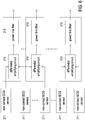
- FIG. 6 is a circuit diagram illustrating the non-contact ECG acquisition module according to another embodiment of the present invention.
- the non-contact ECG acquisition module 21 includes more than three non-contact ECG sensors 211, more than two differential amplifying circuits 212 and more than two power line filters 213.
- the non-contact ECG sensors 211 capture the ECG signals, and then the ECG signals are pre-processed by the non-contact ECG acquisition module 21.
- a pair of non-contact ECG sensors can provide one differential ECG signal, which is further filtered by the power line filter 213.
- the ECG signal pre-processing further includes ground equalization, isolated gain, and other differential subsystems. All parameters for the ECG signal pre-processing are tunable from a microcontroller 23 of the wearable device 20, and this allows tuning of circuitries for different users.
- the non-contact audio acquisition module 22 includes two or more non-contact audio sensors for capturing a respiratory sound signal and a heart sound signal from the user wearing the wearable device 20.
- FIG. 7 is a diagram illustrating the positions of the two non-contact audio sensors on a human body while wearing the wearable device. When the user is wearing the wearable device 20, the two non-contact audio sensors will be placed at the positions shown as grey hexagons in FIG. 7 .
- the primary non-contact audio sensor is located at the lung area in the right chest, and the auxiliary non-contact audio sensor is located at the heart area in the left chest, so as to capture the respiratory sound signal by the primary audio path and capture the heart sound signal by the secondary audio path, respectively.
- the non-contact audio sensor is a MEMS (microelectro-mechanical system) microphone sensor.
- FIG. 8 is a schematic view illustrating the non-contact audio sensor.
- the non-contact audio sensor includes an audio sensor chip 221, a flexible PCB board 222, an acoustic chamber 223 and a holder 224.
- the audio sensor chip 221 is mounted on the flexible PCB board 222, and the flexible PCB board 222 is assembled with the acoustic chamber 223 by the holder 224 to form an integrated component.
- the bell-shaped acoustic chamber 223 totally encloses the audio sensor chip 221 and uses bell-shaped waveguide to optimize transfer of sound from user's body to the audio sensor chip 221 while blocking external soundwave, so as to amplify lung or heart sound and attenuate external undesirable sound.
- the wearable device 20 also includes a microcontroller 23, a first signal processing and analysis module 24, a data storage 25 and a first transceiver 26, which are all embedded in the wearable device 20.
- the microcontroller 23 is connected with the non-contact ECG acquisition module 21 and the non-contact audio acquisition module 22, and transmits the ECG signals and the audio signals from the non-contact ECG acquisition module 21 and the non-contact audio acquisition module 22 to the first signal processing and analysis module 24 for further processing.
- the first signal processing and analysis module 24 includes a digital signal processor.
- the captured signals and processed data can be stored in the data storage 25.
- the data storage 25 is a flash memory.
- the microcontroller 23 manages the operations of the non-contact ECG acquisition module 21, the non-contact audio acquisition module 22, and the first signal processing and analysis module 24.
- the microcontroller 23 also manages the operations of the data storage 25, and manages the communication with the portable device 30 through the first transceiver 26.
- the microcontroller 23 is a Bluetooth microcontroller
- the first transceiver 26 is a Bluetooth transceiver.
- the wearable device 20 further includes a battery charging module 27, a battery 28 and a power supply module 29.
- the wearable device 20 is powered by the battery 28.
- the battery 28 is a lithium polymer battery but not limited thereto.
- the battery charging module 27 is connected with the battery 28 and manages the charging procedure of the battery 28.
- the power supply module 29 is connected with the battery 28 and converts the power from the battery 28 into the required voltages for the non-contact ECG acquisition module 21, the non-contact audio acquisition module 22, the microcontroller 23, the first signal processing and analysis module 24, the data storage 25 and the first transceiver 26.
- FIG. 9 is a schematic view illustrating the wearable device
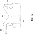
- FIG. 10 is another schematic view illustrating the wearable device in wearing state.
- the wearable device 20 is a wearable vest, which is used to host the non-contact ECG acquisition module 21 and the non-contact audio acquisition module 22 and to make sure the wearer comfortable.
- the wearable device 20 is with two-layer design which is fully detachable.
- the wearable device 20 includes an outer layer 201 and an inner layer 202.
- the outer layer 201 is made of elastic fabric and hence it is stretchable and can apply pressure to the body of the wearer.
- the inner layer 202 is made of meshed clothing with 100% cotton which is comfortable for users to wear.
- the non-contact ECG acquisition module 21 and the non-contact audio acquisition module 22 and wires thereof are attached to the inner layer 202 and deployed between the outer layer 201 and the inner layer 202.
- the outer layer 201 and the inner layer 202 are bonded together using snap fasteners, so the wearable device 20 is washable to fulfill the requirement for hygiene purpose.
- the design of the wearable device 20 makes the non-contact ECG acquisition module 21 and the non-contact audio acquisition module 22 fastened firmly to the proper positions to obtain signals with good quality. Accordingly, the wearable device 20 is able to provide safety, capability, convenience and comfort to the users.
- all sensors of the non-contact ECG acquisition module 21 and the non-contact audio acquisition module 22 are built as flexible PCB to make the wearable device 20 comfortable for the user to wear.
- each of the sensors is independently attached to a patch, and the sensor patches are sewed to the proper positions in the inner-side of the inner layer 202 to hold the sensors. Therefore, the non-contact ECG acquisition module 21 and the non-contact audio acquisition module 22 are deployed between the outer layer 201 and the inner layer 202, and the sensors of the modules 21 and 22 are fastened firmly to the proper positions and face the human body to obtain signals with good quality.
- an inner conduit is provided to contain wires of the non-contact ECG acquisition module 21 and the non-contact audio acquisition module 22 therein so the wires are invisible to the user.
- the inner conduit is also sewed to the inner-side of the inner layer 202 and deployed between the outer layer 201 and the inner layer 202.
- rubber pads are provided under the sensor patches of the non-contact ECG acquisition module 21 to make the ECG sensors more protruding so that the wearable device 20 needs not to be too tight.
- the wearable device 20 includes two bonding parts 203 located at two open sides of the wearable device 20, which makes the wearable device 20 convenient to put on.
- the two bonding parts 203 are hook-and-loop fasteners, such as Vecro. It is flexible for the user with different sizes by adjusting the bonding position of two bonding parts 203.
- the wearable device 20 uses conductive clothing adopted for soft grounding.
- the wearable device 20 includes a two-section strip 204 made of conductive clothing to ensure secure grounding.
- the two-section strip 204 includes a first portion 2041 and a second portion 2042.
- the first portion 2041 is connected with the electronic components in the wearable device 20, such as the non-contact ECG acquisition module 21 and the non-contact audio acquisition module 22.
- the second portion 2042 is connected with the first portion 2041, and is replaceable to replace the worn-out portion.
- a deep-V collar 205 is provided around the neck of the wearer, and two large indentations 206 are provided around the shoulders and arms of the wearer, which are designed to leave more space to the wearer to make him feel comfortable.
- the large indentations 206 make the wearable device 20 less movable while the wearer moving his arms. Therefore, the ECG signals can be obtained with high quality because of reduced interference.
- the wearable device 20 further includes a pocket 207 disposed on the outside of the wearable device 20.
- the pocket 207 is used to accommodate hard components of the system, such as the battery 28, so that wearable device 20 is comfortable for the user to wear.
- the portable device 30 includes a second transceiver 31, an application (App) 32 and a first database 33.
- the second transceiver 31 of the portable device 30 is communicated with the first transceiver 26.
- the second transceiver 31 is also a Bluetooth transceiver, and the communication between the first transceiver 26 and the second transceiver 31 is through the Bluetooth protocol catered for low power consumption.
- NFC Near Field Communication
- the App 32 is designed to communicate with the wearable device 20 for its operation and data transmission, and also communicate with the server 40 for its operation and data transmission.
- the data can be stored in the first database 33 and can be observed on the portable device 30 for result display or further uploaded to the server 40 through internet web services, such as mobile data network.
- the portable device 30 provides various functionalities.
- the portable device 30 is able to provide system control, result display and cloud services.
- the portable device 30 can display the real-time waveforms of the signals for real-time monitoring.
- the user may listen to the lungs/heart sounds through the portable device 30.
- the user can control the system 1 via the portable device 30.
- the portable device 30 can display or issue the warning/alarm signal when the user is in need of care or emergency medical treatments.
- the server 40 includes a cloud server 41, a second signal processing and analysis module 42 and a second database 43.
- the cloud server 41 is interacted with the application 32 of the portable device 30 through the internet web services to receive the data transmitted from the portable device 30 by the application 32.
- the received data including the ECG signals and the audio signals, can be further processed by the second signal processing and analysis module 42.
- the received data and the processed data can be stored in the second database 43.
- FIG. 11 is a diagram illustrating a method for health condition monitoring according to an embodiment of the present invention.
- the ECG signal obtained by the non-contact ECG acquisition module 21 is first filtered to remove the baseline wandering and other noise out of the desired band.
- the filtering can be realized by different techniques according to the application scenario, and can be performed in both the first signal processing and analysis module 24 of the wearable device 20 and the second signal processing and analysis module 42 of the server 40.
- the filtering can be implemented by some sophisticated technique such as non-linear filtering to retain the details in the waveform of the signal.
- the filtering can be implemented by some simple technique such as linear filtering.
- the bandwidth used in the present invention depends on the characteristics of the ECG signal obtained by the non-contact ECG acquisition module 21.
- the bandwidth used in filtering the ECG signal obtained by the non-contact ECG acquisition module 21 applied to the side of the user's body is 0.67-150 Hz.
- the bandwidth 10-50 Hz is used in filtering the ECG signal to acquire a reliable QRS detection.
- waveform analysis and peak detection are conducted to the filtered ECG signal.
- Different techniques can be used to do this.
- a derivative processing based technique can be used in the first signal processing and analysis module 24 of the wearable device 20 to detect the QRS complex, while in the second signal processing and analysis module 42 of the server 40, a template matching based technique can be applied to do this job.
- FIG. 12 is a diagram illustrating the QRS detection in the wearable device which uses a derivative processing based technique.
- the filtered ECG signal is differentiated to provide the QRS complex slope information.
- the signal is squared point by point to attenuate the noise and emphasize the ECG components (i.e. the ECG frequencies).
- the moving-window integration is applied to obtain the waveform feature information of the R wave.
- the QRS complex corresponds to the rising edge of the integration waveform.
- a fiducial mark for the temporal location of the QRS complex can be determined from this rising edge.
- the threshold will be adjusted automatically to float over the noisy/interference components.
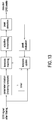
- FIG. 13 is a diagram illustrating the QRS detection in the server which uses a template matching based technique.
- the template pre-stored in the system will be used during the initial phase.
- the template matching is conducted by correlating the template model with the filtered ECG signal.
- Adaptive thresholding is then applied to detect the R peaks.
- the detected peaks will be evaluated, and IBI (inter-beat interval) will be calculated.
- IBI inter-beat interval
- Those intervals which exceed the pre-defined percentage (e.g. 120%) of their previous intervals will be treated as unreliable and the corresponding peaks will be discarded.
- the corresponding QRS complex will be used to update the template.
- the template will be updated regularly once the timer reaches the pre-defined value of time duration (e.g. 10 seconds).
- the output of the waveform analysis and QRS detection will be used to do the feature extraction and heart rate (HR) and heart rate variability (HRV) calculation, as shown in FIG. 11 .
- HR heart rate
- HRV heart rate variability
- the respiratory sound signal and the heart sound signal captured by the two non-contact audio sensors of the non-contact audio acquisition module 22 are first processed in the first signal processing and analysis module 24 of the wearable device 20 for bandpass filtering and adaptive noise cancellation (ANC).
- the first signal processing and analysis module 24 includes an adaptive filter with ANC configuration. As shown in FIG. 9 , the respiratory sound signal and the heart sound signal are first filtered to compress the components out of the desired band. Then the adaptive filter with ANC configuration is applied to suppress both the ambient noise and the heart sound simultaneously.
- the system 1 for health condition monitoring uses a dual-channel framework consisting of two audio sensors.
- the heart sound signal captured by the auxiliary non-contact audio sensor and the respiratory sound signal captured by primary non-contact audio sensor constitute the configuration of ANC, where both the ambient noise and the heart sound will be suppressed.
- the heart sound signal captured by the auxiliary non-contact audio sensor is not only used as a part of the ANC configuration to suppress the heart sound, but also used to estimate the locations of heart sound portions with an algorithm proposed in the present invention, which is named multiband products based on FFT (fast Fourier transform) coefficients.
- the short-time Fourier transform (STFT) is applied to the filtered heart sound signal from the auxiliary non-contact audio sensor every particular time period to transform it into frequency domain. Setting the time period to a pre-defined value N 1 , where N 1 ranges from 10 ms to 1000 ms. In an embodiment, N 1 ranges from 32 ms to 64 ms.
- the overlap between the successive frames could be 0-100%. In an embodiment, the overlap between the successive frames is 20-80%, more preferably 40-60%, and most preferably 50%.
- the multiband product P j,k is compared with an adaptive threshold. If the multiband product P j,k is greater than the adaptive threshold, the corresponding ⁇ is identified as belonging to the heart sound portion.
- the accuracy of estimation of heart sound locations can be improved by combining the information provided by ECG signals and the locations estimated from the audio signals.
- ECG signal and the heart sound signal pre-ejection period (PEP), which is the time interval from R-peak of ECG to the first heart sound (S1) of PCG (phonocardiogram) recorded from the chest. Since ECG signal and the respiratory sound signal are collected at the same time and the approximate value of PEP is around 100 ms, when the R-peak is detected, the processed respiratory sound signal can be searched at the portion about 100 ms apart from the point of the R-peak. Therefore S1 can be identified with higher accuracy.
- the information of accurate locations of heart sounds is then exploited in the further step to remove the residual heart sound from the output of the ANC for heart sound cancellation.
- the restoration of respiratory sound during the removed heart sound portions can be done by estimating the removed data by linear prediction, using either autoregressive (AR) or moving average (MA) models.
- the STFT is applied to the signal at the output of ANC similar as described in Paragraph [0052], therefore FFT coefficients S ANC ( ⁇ , f) are obtained.
- the information is used in the ANC path, i.e. the FFT coefficients in S ANC ( ⁇ , f) corresponding to the heart sound portions will be removed from S ANC ( ⁇ , f).
- the gap between two successive respiratory sound portions is filled in by interpolated FFT coefficients obtained from the linear prediction.
- the linear prediction is conducted in each sub-band of the desired frequency bands, using either AR or MA models.
- the refurbished FFT coefficients after interpolation are denoted as S ANC,r ( ⁇ , f).
- IFFT inverse FFT
- Respiratory rate can be estimated from ECG signals. After the R-peak detection is done, IBI can be calculated from the locations of R-peaks. Applying spectrum analysis to the IBI, the respiratory rate can be estimated by searching the maximum point in the frequency range of 0.2-1 Hz of the spectrum. Accordingly, the ECG derived RR is obtained.
- the respiratory rate can also be estimated from the cleaned respiratory signals after heart sound cancellation by a spectral processing method.
- the autocorrelation function is applied to this result and generally the second peak in the autocorrelation represents the RR. Accordingly, the sound based RR is obtained. However in the case when one respiratory phase is more prominent, the RR may be better estimated by the first peak.
- This method includes a logical analysis to choose the weights used in the RR combination, i.e. the weight will be assigned based on the quality of the signal itself. The signal with better quality will be assigned a heavier weight. The evaluation of signal quality will be approximated by the peak evaluation mentioned in the ECG signal processing.
- the RR-interval is corrected to get the NN-interval.
- the difference between the NN-interval and the RR-interval, i.e. the percentage on the number of RR-intervals that have been rectified, can be used as an indicator of the quality of the ECG signal.
- the values of weight pairs can be determined based on the indicator by looking up the table pre-defined in the system.
- the data fusion may be used in different levels and aspects.
- the data fusion may be used in localizing heart sound portions from respiratory sound by combining position information derived from the secondary audio path and that from ECG signal.
- the data fusion may be used in calculation of RR by combining RR estimate derived from ECG signal and RR estimate derived from respiratory sound.
- the data fusion may be used in weighted RR combination by a score system based on logical analysis, i.e. RR estimate from better signal quality is assigned a heavier weight while signal quality is evaluated by the percentage of the number of RR intervals to be corrected to get NN-interval in ECG.
- the data fusion may also be used in identification of specific events and health condition analysis by combing all information derived from the whole feature space, which is spanned by the individual spaces from ECG and respiration respectively.
- FIG. 14 is a flow chart illustrating a method for health condition monitoring according to an embodiment of the present invention.
- a wearable device a portable device and a server are provided (Step S51).
- the wearable device includes an embedded non-contact ECG acquisition module, an embedded non-contact audio acquisition module and an embedded first signal processing and analysis module.
- the portable device is capable of communicating between the wearable device and the server.
- the server includes a second signal processing and analysis module.
- ECG signals are captured by the non-contact ECG acquisition module, and a respiratory sound signal and a heart sound signal are captured by the non-contact audio acquisition module from the user wearing the wearable device (Step S52).
- the ECG signals, the respiratory sound signal and the heart sound signal are processed by the first signal processing and analysis module to perform QRS detection, HR calculation and ECG derived RR determination (Step S53).
- the ECG signals, the respiratory sound signal and the heart sound signal are processed by the second signal processing and analysis module to perform heart sound localization, heart sound cancellation, respiratory sound restoration, and sound based RR determination, and thus obtaining information for health condition monitoring (Step S54).
- a final result of RR from the ECG derived RR and the sound based RR is obtained by a weighted method, where the RR from better signal quality is assigned a heavier weight.
- the present invention provides a system and a method for health condition monitoring.
- the inventive system for health condition monitoring includes a wearable device, a portable device and a server.
- the non-contact ECG acquisition module and the non-contact audio acquisition module used to acquire ECG signals and audio signals are embedded in the wearable device and do not directly contact the skin of the user, which fulfils the requirement of hygiene purpose and makes the wearer feel comfortable to improve the compliance of long term use.
- the wearable device is designed to provide safety, capability, convenience and comfort to the users.
- the wearable device also includes a signal processing and analysis module capable of performing QRS detection, HR calculation and ECG derived RR determination. Other signal processing and analysis may be performed on the server side.
- the dual-channel framework consisting of two audio sensors are used to capture the respiratory sound signal and the heart sound signal, and the multiband products based on FFT coefficients are used for the heart sound localization and the heart sound cancellation.
- the features extracted from ECG signals, the respiratory sound signal and the heart sound signal can be further combined by data fusion analysis to give the final results on condition analysis for the heart and the lung of the user.
- the doctors, caretakers and family members of the user can retrieve data or be informed of situation where the user is in need of care or emergency medical treatments.
- the present invention provides a system and a method for health condition monitoring incorporating ECG and audio sensors, which can be used for the detection, recording, and analysis of signals related to heart and lung functions, anywhere and over a long duration, including treatment response/rehabilitation. Further, the proposed system and method for health condition monitoring may also provide early warning of chronic diseases or alarm for fatigue, stress level etc. Thus, the proposed system and method provide not only current monitoring but also preventative monitoring for health conditions of the user.
Landscapes
- Health & Medical Sciences (AREA)
- Life Sciences & Earth Sciences (AREA)
- Engineering & Computer Science (AREA)
- Cardiology (AREA)
- Animal Behavior & Ethology (AREA)
- Veterinary Medicine (AREA)
- Public Health (AREA)
- Biomedical Technology (AREA)
- Heart & Thoracic Surgery (AREA)
- Medical Informatics (AREA)
- Molecular Biology (AREA)
- Surgery (AREA)
- General Health & Medical Sciences (AREA)
- Physics & Mathematics (AREA)
- Biophysics (AREA)
- Pathology (AREA)
- Pulmonology (AREA)
- Physiology (AREA)
- Signal Processing (AREA)
- Computer Networks & Wireless Communication (AREA)
- Artificial Intelligence (AREA)
- Computer Vision & Pattern Recognition (AREA)
- Psychiatry (AREA)
- Medical Treatment And Welfare Office Work (AREA)
- Measuring And Recording Apparatus For Diagnosis (AREA)
- Measurement Of The Respiration, Hearing Ability, Form, And Blood Characteristics Of Living Organisms (AREA)
- Measurement And Recording Of Electrical Phenomena And Electrical Characteristics Of The Living Body (AREA)
Abstract
Description
- The present invention relates to a system and a method for health condition monitoring, and more particularly to a system and a method for health condition monitoring suitable for long term use.
- Nowadays, chronic heart problems and respiratory disorders are common progressive diseases, which are major causes of disabilities and leading causes of death. Monitoring and management of these diseases are important for medical care and can improve the quality of life for patients. In a wider circumstance, preventative monitoring allows health disorders to be detected during activities for military personnel while performance monitoring helps to improve the training via heart rate and breathing for sportsmen.
- Frequent monitoring of heart and respiratory functions can provide crucial information but frequent visit to hospitals is costly and inconvenient. Thus, some electronic systems have been developed for health condition monitoring. However, these systems restrict the movement of the user and may require the user to be physically connected to stationary machines, which is inconvenient and uncomfortable for use or even long term use. In addition, these systems either only monitor single function for heart or lung or can detect both heart and lung activities only within short period of time.
- Therefore, there is a need of providing a system and a method for health condition monitoring to obviate the drawbacks encountered from the prior arts.
- An object of the present invention is to provide a system and a method for health condition monitoring which can monitor both the heart and the lung functions of the user at anywhere and over a long duration with comfort.
- In accordance with an aspect of the present invention, there is provided a system for health condition monitoring including a wearable device, a portable device and a server. The portable device is capable of communicating between the wearable device and the server. The system for health condition monitoring further includes a non-contact ECG (electrocardiography) acquisition module, a non-contact audio acquisition module, a first signal processing and analysis module and a second signal processing and analysis module. The non-contact ECG acquisition module is embedded in the wearable device for capturing ECG signals from a user wearing the wearable device. The non-contact audio acquisition module is embedded in the wearable device for capturing a respiratory sound signal and a heart sound signal from the user wearing the wearable device. The first signal processing and analysis module is embedded in the wearable device and connected with the non-contact ECG acquisition module and the non-contact audio acquisition module. The first signal processing and analysis module is used for receiving and processing the ECG signals, the respiratory sound signal and the heart sound signal from the non-contact ECG acquisition module and the non-contact audio acquisition module. Particularly, QRS detection, HR (heart rate) calculation and ECG derived RR (respiratory rate) determination are performed in the first signal processing and analysis module. The second signal processing and analysis module is provided on the server for receiving and processing the ECG signals, the respiratory sound signal and the heart sound signal uploaded by the portable device. Particularly, heart sound localization, heart sound cancellation, respiratory sound restoration, and sound based RR determination are performed in the second signal processing and analysis module, so as to obtain information for health condition monitoring.
- In accordance with another aspect of the present invention, there is provided a method for health condition monitoring. The method includes steps of: (a) providing a wearable device, a portable device and a server, the wearable device comprising an embedded non-contact ECG acquisition module, an embedded non-contact audio acquisition module and an embedded first signal processing and analysis module, the portable device being capable of communicating between the wearable device and the server, the server comprising a second signal processing and analysis module; (b) capturing ECG signals by the non-contact ECG acquisition module and capturing a respiratory sound signal and a heart sound signal by the non-contact audio acquisition module from the user wearing the wearable device; (c) processing the ECG signals, the respiratory sound signal and the heart sound signal by the first signal processing and analysis module to perform QRS detection, HR (heart rate) calculation and ECG derived RR (respiratory rate) determination; and (d) processing the ECG signals, the respiratory sound signal and the heart sound signal by the second signal processing and analysis module to perform heart sound localization, heart sound cancellation, respiratory sound restoration, and sound based RR determination, and thus obtaining information for health condition monitoring.
-
-
FIG. 1 is a diagram illustrating a system for health condition monitoring according to an embodiment of the present invention; -
FIG. 2 is a diagram illustrating a system for health condition monitoring according to another embodiment of the present invention; -
FIG. 3 is a detailed diagram illustrating the system for health condition monitoring ofFIG. 1 ; -
FIG. 4 is a diagram illustrating the positions of the three non-contact ECG sensors on a human body while wearing the wearable device; -
FIG. 5 is a circuit diagram illustrating the non-contact ECG acquisition module according to an embodiment of the present invention; -
FIG. 6 is a circuit diagram illustrating the non-contact ECG acquisition module according to another embodiment of the present invention; -
FIG. 7 is a diagram illustrating the positions of the two non-contact audio sensors on a human body while wearing the wearable device; -
FIG. 8 is a schematic view illustrating the non-contact audio sensor; -
FIG. 9 is a schematic view illustrating the wearable device; -
FIG. 10 is another schematic view illustrating the wearable device in wearing state; -
FIG. 11 is a diagram illustrating a method for health condition monitoring according to an embodiment of the present invention; -
FIG. 12 is a diagram illustrating the QRS detection in the wearable device; -
FIG. 13 is a diagram illustrating the QRS detection in the server; and -
FIG. 14 is a flow chart illustrating a method for health condition monitoring according to an embodiment of the present invention. - The present disclosure will now be described more specifically with reference to the following embodiments. It is to be noted that the following descriptions of preferred embodiments of this disclosure are presented herein for purpose of illustration and description only. It is not intended to be exhaustive or to be limited to the precise form disclosed.
-
FIG. 1 is a diagram illustrating a system for health condition monitoring according to an embodiment of the present invention. As shown inFIG. 1 , thesystem 1 for health condition monitoring includes awearable device 20, aportable device 30 and aserver 40. When thewearable device 20 is worn by a user, the ECG (electrocardiography), the heart sound and the respiratory sound of the user can be acquired. Thewearable device 20 can communicate with theportable device 30 for data transmission. Moreover, the data can be further uploaded to theserver 40 through the internet web services. By means of theportable device 30 and theserver 40, the doctors, caretakers and family members of the user can retrieve data or be informed of situation where the user is in need of care or emergency medical treatments. Preferably but not exclusively, thewearable device 20 is a wearable vest and theportable device 30 is a smart phone or a tablet. -
FIG. 2 is a diagram illustrating a system for health condition monitoring according to another embodiment of the present invention. As shown inFIG. 2 , thesystem 1 may include pluralwearable devices portable devices wearable devices 20A may communicate with the sameportable device 30A, and the pluralwearable devices 20B may communicate with the sameportable device 30B. For example, the pluralwearable devices 20A may be worn by family members, so that the health conditions of the family may be monitored on the sameportable device 30A. Similarly, the pluralwearable devices 20B may be worn by members of another family, sport team or military unit, so as to monitor the health conditions of the members for the same group on the sameportable device 30B. -
FIG. 3 is a detailed diagram illustrating the system for health condition monitoring ofFIG. 1 . As shown inFIG. 3 , thewearable device 20 includes a non-contactECG acquisition module 21 and a non-contactaudio acquisition module 22 to acquire ECG signals and audio signals, respectively, from the user wearing thewearable device 20. The non-contactECG acquisition module 21 and the non-contactaudio acquisition module 22 are embedded in thewearable device 20 and do not directly contact the skin of the user. In other words, direct skin contact is not necessary for thesystem 1 for health condition monitoring of the present invention, so the user can be fully clothed. This not only fulfils the requirement of hygiene purpose but also makes the wearer feel comfortable to improve the compliance of long term use. - In an embodiment, the non-contact
ECG acquisition module 21 includes three or more non-contact ECG sensors.FIG. 4 is a diagram illustrating the positions of the three non-contact ECG sensors on a human body while wearing the wearable device. When the user is wearing thewearable device 20, the three non-contact ECG sensors will be placed at the positions shown as grey circles inFIG. 4 , which are at the top of the manubrium, the left side of the ninth rib, and the right side of the ninth rib. The ECG signals captured from the non-contact ECG sensors located at the top of the manubrium vs. the left side of the ninth rib have similar waveform as the traditional ECG. In addition, since there are relatively less muscles at both sides of the ninth rib, the ECG signals captured from the non-contact ECG sensors located at the left side of the ninth rib vs. the right side of the ninth rib are interfered less by muscle movement, and are thus chosen for ECG signal records during exercises. - The non-contact
ECG acquisition module 21 is used for capturing ECG signals from the user wearing thewearable device 20 through the non-contact ECG sensors.FIG. 5 is a circuit diagram illustrating the non-contact ECG acquisition module according to an embodiment of the present invention. As shown inFIG. 5 , the non-contactECG acquisition module 21 includes threenon-contact ECG sensors 211 based on capacitance, twodifferential amplifying circuits 212 and two power line filters 213. The threenon-contact ECG sensors 211 capture the ECG signals, and then the ECG signals are pre-processed by the non-contactECG acquisition module 21. A pair ofnon-contact ECG sensors 211 will provide one differential ECG signal. In an embodiment, the ECG signals from pairednon-contact ECG sensors 211, i.e. sensors located at the top of the manubrium vs. the left side of the ninth rib and sensors located at the left side of the ninth rib vs. the right side of the ninth rib, are differentiated by thedifferential amplifying circuit 212 and then filtered by thepower line filter 213. Accordingly, two sets of differential ECG signals are acquired from the threenon-contact ECG sensors 211 in thewearable device 20. One set of differential non-contact ECG signal provides an ECG signal that emulates 3-leads ECG, while another set of differential non-contact ECG signal provides an ECG signal that is robust to motions of user's daily activities. The emulated 3-leads ECG allows medical practitioners to examine user's ECG signal they are familiar with while the robust ECG signals are used for IBI (inter-beat interval) computation. - Therefore, by means of the three
non-contact ECG sensors 211 and the dualdifferential amplifying circuits 212, the non-contactECG acquisition module 21 is configured to emulate conventional 3-leads ECG output, and is resistant to motions of user and suitable for long term signal acquisition. - Nevertheless, the numbers of the
non-contact ECG sensors 211, thedifferential amplifying circuits 212 and the power line filters 213 included in the non-contactECG acquisition module 21 are not limited to those shown inFIG. 5 .FIG. 6 is a circuit diagram illustrating the non-contact ECG acquisition module according to another embodiment of the present invention. As shown inFIG. 6 , the non-contactECG acquisition module 21 includes more than threenon-contact ECG sensors 211, more than twodifferential amplifying circuits 212 and more than two power line filters 213. Thenon-contact ECG sensors 211 capture the ECG signals, and then the ECG signals are pre-processed by the non-contactECG acquisition module 21. Similar to the embodiment shown inFIG. 5 , a pair of non-contact ECG sensors can provide one differential ECG signal, which is further filtered by thepower line filter 213. - In an embodiment, the ECG signal pre-processing further includes ground equalization, isolated gain, and other differential subsystems. All parameters for the ECG signal pre-processing are tunable from a
microcontroller 23 of thewearable device 20, and this allows tuning of circuitries for different users. - In an embodiment, the non-contact
audio acquisition module 22 includes two or more non-contact audio sensors for capturing a respiratory sound signal and a heart sound signal from the user wearing thewearable device 20.FIG. 7 is a diagram illustrating the positions of the two non-contact audio sensors on a human body while wearing the wearable device. When the user is wearing thewearable device 20, the two non-contact audio sensors will be placed at the positions shown as grey hexagons inFIG. 7 . The primary non-contact audio sensor is located at the lung area in the right chest, and the auxiliary non-contact audio sensor is located at the heart area in the left chest, so as to capture the respiratory sound signal by the primary audio path and capture the heart sound signal by the secondary audio path, respectively. In an embodiment, the non-contact audio sensor is a MEMS (microelectro-mechanical system) microphone sensor. -
FIG. 8 is a schematic view illustrating the non-contact audio sensor. As shown inFIG. 8 , the non-contact audio sensor includes anaudio sensor chip 221, aflexible PCB board 222, anacoustic chamber 223 and aholder 224. Theaudio sensor chip 221 is mounted on theflexible PCB board 222, and theflexible PCB board 222 is assembled with theacoustic chamber 223 by theholder 224 to form an integrated component. The bell-shapedacoustic chamber 223 totally encloses theaudio sensor chip 221 and uses bell-shaped waveguide to optimize transfer of sound from user's body to theaudio sensor chip 221 while blocking external soundwave, so as to amplify lung or heart sound and attenuate external undesirable sound. - Referring to
FIG. 3 again. Thewearable device 20 also includes amicrocontroller 23, a first signal processing andanalysis module 24, adata storage 25 and afirst transceiver 26, which are all embedded in thewearable device 20. Themicrocontroller 23 is connected with the non-contactECG acquisition module 21 and the non-contactaudio acquisition module 22, and transmits the ECG signals and the audio signals from the non-contactECG acquisition module 21 and the non-contactaudio acquisition module 22 to the first signal processing andanalysis module 24 for further processing. In an embodiment, the first signal processing andanalysis module 24 includes a digital signal processor. The captured signals and processed data can be stored in thedata storage 25. In an embodiment, thedata storage 25 is a flash memory. Themicrocontroller 23 manages the operations of the non-contactECG acquisition module 21, the non-contactaudio acquisition module 22, and the first signal processing andanalysis module 24. Themicrocontroller 23 also manages the operations of thedata storage 25, and manages the communication with theportable device 30 through thefirst transceiver 26. Preferably but not exclusively, themicrocontroller 23 is a Bluetooth microcontroller, and thefirst transceiver 26 is a Bluetooth transceiver. - The
wearable device 20 further includes abattery charging module 27, abattery 28 and apower supply module 29. Thewearable device 20 is powered by thebattery 28. In an embodiment, thebattery 28 is a lithium polymer battery but not limited thereto. Thebattery charging module 27 is connected with thebattery 28 and manages the charging procedure of thebattery 28. Thepower supply module 29 is connected with thebattery 28 and converts the power from thebattery 28 into the required voltages for the non-contactECG acquisition module 21, the non-contactaudio acquisition module 22, themicrocontroller 23, the first signal processing andanalysis module 24, thedata storage 25 and thefirst transceiver 26. -
FIG. 9 is a schematic view illustrating the wearable device, andFIG. 10 is another schematic view illustrating the wearable device in wearing state. As shown inFIGS. 9 and10 , thewearable device 20 is a wearable vest, which is used to host the non-contactECG acquisition module 21 and the non-contactaudio acquisition module 22 and to make sure the wearer comfortable. Thewearable device 20 is with two-layer design which is fully detachable. Thewearable device 20 includes anouter layer 201 and aninner layer 202. Theouter layer 201 is made of elastic fabric and hence it is stretchable and can apply pressure to the body of the wearer. Theinner layer 202 is made of meshed clothing with 100% cotton which is comfortable for users to wear. The non-contactECG acquisition module 21 and the non-contactaudio acquisition module 22 and wires thereof are attached to theinner layer 202 and deployed between theouter layer 201 and theinner layer 202. Theouter layer 201 and theinner layer 202 are bonded together using snap fasteners, so thewearable device 20 is washable to fulfill the requirement for hygiene purpose. Most important, the design of thewearable device 20 makes the non-contactECG acquisition module 21 and the non-contactaudio acquisition module 22 fastened firmly to the proper positions to obtain signals with good quality. Accordingly, thewearable device 20 is able to provide safety, capability, convenience and comfort to the users. - In an embodiment, all sensors of the non-contact
ECG acquisition module 21 and the non-contactaudio acquisition module 22 are built as flexible PCB to make thewearable device 20 comfortable for the user to wear. To secure the ECG sensors of the non-contactECG acquisition module 21 and the audio sensors of the non-contactaudio acquisition module 22 to the proper positions of the human body, each of the sensors is independently attached to a patch, and the sensor patches are sewed to the proper positions in the inner-side of theinner layer 202 to hold the sensors. Therefore, the non-contactECG acquisition module 21 and the non-contactaudio acquisition module 22 are deployed between theouter layer 201 and theinner layer 202, and the sensors of themodules - In an embodiment, an inner conduit is provided to contain wires of the non-contact
ECG acquisition module 21 and the non-contactaudio acquisition module 22 therein so the wires are invisible to the user. The inner conduit is also sewed to the inner-side of theinner layer 202 and deployed between theouter layer 201 and theinner layer 202. In addition, rubber pads are provided under the sensor patches of the non-contactECG acquisition module 21 to make the ECG sensors more protruding so that thewearable device 20 needs not to be too tight. - In an embodiment, the
wearable device 20 includes twobonding parts 203 located at two open sides of thewearable device 20, which makes thewearable device 20 convenient to put on. Preferably but not exclusively, the twobonding parts 203 are hook-and-loop fasteners, such as Vecro. It is flexible for the user with different sizes by adjusting the bonding position of twobonding parts 203. - In an embodiment, the
wearable device 20 uses conductive clothing adopted for soft grounding. Thewearable device 20 includes a two-section strip 204 made of conductive clothing to ensure secure grounding. The two-section strip 204 includes afirst portion 2041 and asecond portion 2042. Thefirst portion 2041 is connected with the electronic components in thewearable device 20, such as the non-contactECG acquisition module 21 and the non-contactaudio acquisition module 22. Thesecond portion 2042 is connected with thefirst portion 2041, and is replaceable to replace the worn-out portion. - As shown in
FIG. 10 , a deep-V collar 205 is provided around the neck of the wearer, and twolarge indentations 206 are provided around the shoulders and arms of the wearer, which are designed to leave more space to the wearer to make him feel comfortable. Besides, thelarge indentations 206 make thewearable device 20 less movable while the wearer moving his arms. Therefore, the ECG signals can be obtained with high quality because of reduced interference. - In an embodiment, the
wearable device 20 further includes apocket 207 disposed on the outside of thewearable device 20. Thepocket 207 is used to accommodate hard components of the system, such as thebattery 28, so thatwearable device 20 is comfortable for the user to wear. - Referring to
FIG. 3 again. Theportable device 30 includes asecond transceiver 31, an application (App) 32 and afirst database 33. Thesecond transceiver 31 of theportable device 30 is communicated with thefirst transceiver 26. Preferably but not exclusively, thesecond transceiver 31 is also a Bluetooth transceiver, and the communication between thefirst transceiver 26 and thesecond transceiver 31 is through the Bluetooth protocol catered for low power consumption. NFC (Near Field Communication) system is used to power up thewearable device 20 from deep sleep and pairing for Bluetooth, which removes the need for mechanical switches and button forwearable device 20. TheApp 32 is designed to communicate with thewearable device 20 for its operation and data transmission, and also communicate with theserver 40 for its operation and data transmission. The data can be stored in thefirst database 33 and can be observed on theportable device 30 for result display or further uploaded to theserver 40 through internet web services, such as mobile data network. - Except for data transmission, the
portable device 30 provides various functionalities. By the customizedApp 32, theportable device 30 is able to provide system control, result display and cloud services. For example, theportable device 30 can display the real-time waveforms of the signals for real-time monitoring. The user may listen to the lungs/heart sounds through theportable device 30. The user can control thesystem 1 via theportable device 30. Moreover, theportable device 30 can display or issue the warning/alarm signal when the user is in need of care or emergency medical treatments. - The
server 40 includes acloud server 41, a second signal processing andanalysis module 42 and asecond database 43. Thecloud server 41 is interacted with theapplication 32 of theportable device 30 through the internet web services to receive the data transmitted from theportable device 30 by theapplication 32. The received data, including the ECG signals and the audio signals, can be further processed by the second signal processing andanalysis module 42. The received data and the processed data can be stored in thesecond database 43. -
FIG. 11 is a diagram illustrating a method for health condition monitoring according to an embodiment of the present invention. For ECG signal processing, the ECG signal obtained by the non-contactECG acquisition module 21 is first filtered to remove the baseline wandering and other noise out of the desired band. The filtering can be realized by different techniques according to the application scenario, and can be performed in both the first signal processing andanalysis module 24 of thewearable device 20 and the second signal processing andanalysis module 42 of theserver 40. For example, when the filtering is performed in the second signal processing andanalysis module 42 of theserver 40, the filtering can be implemented by some sophisticated technique such as non-linear filtering to retain the details in the waveform of the signal. When the filtering is performed in the first signal processing andanalysis module 24 of thewearable device 20, the filtering can be implemented by some simple technique such as linear filtering. However, other than the bandwidth usually used in filtering the ECG signal obtained by traditional ECG devices, the bandwidth used in the present invention depends on the characteristics of the ECG signal obtained by the non-contactECG acquisition module 21. In an embodiment, the bandwidth used in filtering the ECG signal obtained by the non-contactECG acquisition module 21 applied to the side of the user's body is 0.67-150 Hz. Particularly, the bandwidth 10-50 Hz is used in filtering the ECG signal to acquire a reliable QRS detection. - After the filtering for baseline wandering removal and noise reduction, waveform analysis and peak detection are conducted to the filtered ECG signal. Different techniques can be used to do this. For example, a derivative processing based technique can be used in the first signal processing and
analysis module 24 of thewearable device 20 to detect the QRS complex, while in the second signal processing andanalysis module 42 of theserver 40, a template matching based technique can be applied to do this job. -
FIG. 12 is a diagram illustrating the QRS detection in the wearable device which uses a derivative processing based technique. The filtered ECG signal is differentiated to provide the QRS complex slope information. After the derivative processing, the signal is squared point by point to attenuate the noise and emphasize the ECG components (i.e. the ECG frequencies). Then the moving-window integration is applied to obtain the waveform feature information of the R wave. The QRS complex corresponds to the rising edge of the integration waveform. A fiducial mark for the temporal location of the QRS complex can be determined from this rising edge. Finally the threshold will be adjusted automatically to float over the noisy/interference components. -
FIG. 13 is a diagram illustrating the QRS detection in the server which uses a template matching based technique. For the template matching based technique, the template pre-stored in the system will be used during the initial phase. The template matching is conducted by correlating the template model with the filtered ECG signal. Adaptive thresholding is then applied to detect the R peaks. The detected peaks will be evaluated, and IBI (inter-beat interval) will be calculated. Those intervals which exceed the pre-defined percentage (e.g. 120%) of their previous intervals will be treated as unreliable and the corresponding peaks will be discarded. For those peaks which pass the evaluation, the corresponding QRS complex will be used to update the template. The template will be updated regularly once the timer reaches the pre-defined value of time duration (e.g. 10 seconds). - Afterward, the output of the waveform analysis and QRS detection will be used to do the feature extraction and heart rate (HR) and heart rate variability (HRV) calculation, as shown in
FIG. 11 . The results of the feature extraction and HR/HRV calculation are not only a part of the final output but also intermediate output that would be exploited in further processing steps. - For audio signal processing, the respiratory sound signal and the heart sound signal captured by the two non-contact audio sensors of the non-contact
audio acquisition module 22 are first processed in the first signal processing andanalysis module 24 of thewearable device 20 for bandpass filtering and adaptive noise cancellation (ANC). In an embodiment, the first signal processing andanalysis module 24 includes an adaptive filter with ANC configuration. As shown inFIG. 9 , the respiratory sound signal and the heart sound signal are first filtered to compress the components out of the desired band. Then the adaptive filter with ANC configuration is applied to suppress both the ambient noise and the heart sound simultaneously. - In other words, the
system 1 for health condition monitoring uses a dual-channel framework consisting of two audio sensors. The heart sound signal captured by the auxiliary non-contact audio sensor and the respiratory sound signal captured by primary non-contact audio sensor constitute the configuration of ANC, where both the ambient noise and the heart sound will be suppressed. - The heart sound signal captured by the auxiliary non-contact audio sensor is not only used as a part of the ANC configuration to suppress the heart sound, but also used to estimate the locations of heart sound portions with an algorithm proposed in the present invention, which is named multiband products based on FFT (fast Fourier transform) coefficients. The short-time Fourier transform (STFT) is applied to the filtered heart sound signal from the auxiliary non-contact audio sensor every particular time period to transform it into frequency domain. Setting the time period to a pre-defined value N1 , where N1 ranges from 10 ms to 1000 ms. In an embodiment, N1 ranges from 32 ms to 64 ms. The number of selected samples in every frame for one STFT is Rs * N1 = Nfft , where Rs is the sampling rate. The overlap between the successive frames could be 0-100%. In an embodiment, the overlap between the successive frames is 20-80%, more preferably 40-60%, and most preferably 50%. The two-dimension representation of the filtered signal along the time and frequency axis is given by the STFT as the following formula:


- The accuracy of estimation of heart sound locations can be improved by combining the information provided by ECG signals and the locations estimated from the audio signals. There is a relationship between the ECG signal and the heart sound signal, pre-ejection period (PEP), which is the time interval from R-peak of ECG to the first heart sound (S1) of PCG (phonocardiogram) recorded from the chest. Since ECG signal and the respiratory sound signal are collected at the same time and the approximate value of PEP is around 100 ms, when the R-peak is detected, the processed respiratory sound signal can be searched at the portion about 100 ms apart from the point of the R-peak. Therefore S1 can be identified with higher accuracy. The information of accurate locations of heart sounds is then exploited in the further step to remove the residual heart sound from the output of the ANC for heart sound cancellation.
- The restoration of respiratory sound during the removed heart sound portions can be done by estimating the removed data by linear prediction, using either autoregressive (AR) or moving average (MA) models. The STFT is applied to the signal at the output of ANC similar as described in Paragraph [0052], therefore FFT coefficients SANC(τ, f) are obtained. Once the heart sound portions are localized, the information is used in the ANC path, i.e. the FFT coefficients in SANC(τ, f) corresponding to the heart sound portions will be removed from SANC(τ, f). The gap between two successive respiratory sound portions is filled in by interpolated FFT coefficients obtained from the linear prediction. The linear prediction is conducted in each sub-band of the desired frequency bands, using either AR or MA models. The refurbished FFT coefficients after interpolation are denoted as SANC,r(τ, f). Then IFFT (inverse FFT) is applied to the refurbished FFT coefficients to restore the respiratory sound. Therefore a cleaner respiratory signal can be used for respiration analysis.
- Respiratory rate (RR) can be estimated from ECG signals. After the R-peak detection is done, IBI can be calculated from the locations of R-peaks. Applying spectrum analysis to the IBI, the respiratory rate can be estimated by searching the maximum point in the frequency range of 0.2-1 Hz of the spectrum. Accordingly, the ECG derived RR is obtained.
- Alternatively, the respiratory rate can also be estimated from the cleaned respiratory signals after heart sound cancellation by a spectral processing method. A quadratic detection function is applied to the FFT coefficients to obtain the spectral parameters. This operation can be performed as follows by multiplying the squared frequency with the power of its FFT coefficients as the following formulas:


- After the RR estimate is derived from the ECG signal and from the audio signals respectively, the sound based RR and the ECG derived RR are then combined by a weighted method to give the final result of RR. A score system is developed as the following formula to determine how to combine the individual estimates:

- This method includes a logical analysis to choose the weights used in the RR combination, i.e. the weight will be assigned based on the quality of the signal itself. The signal with better quality will be assigned a heavier weight. The evaluation of signal quality will be approximated by the peak evaluation mentioned in the ECG signal processing. Before calculating the HRV, the RR-interval is corrected to get the NN-interval. The difference between the NN-interval and the RR-interval, i.e. the percentage on the number of RR-intervals that have been rectified, can be used as an indicator of the quality of the ECG signal. The values of weight pairs can be determined based on the indicator by looking up the table pre-defined in the system.
- At last the features extracted from respiratory signal together with the features extracted from ECG signal, and the features induced from both the respiratory and ECG signals will be combined by data fusion analysis to give the final results on case identification and condition analysis of the wearer.
- The data fusion may be used in different levels and aspects. The data fusion may be used in localizing heart sound portions from respiratory sound by combining position information derived from the secondary audio path and that from ECG signal. The data fusion may be used in calculation of RR by combining RR estimate derived from ECG signal and RR estimate derived from respiratory sound. The data fusion may be used in weighted RR combination by a score system based on logical analysis, i.e. RR estimate from better signal quality is assigned a heavier weight while signal quality is evaluated by the percentage of the number of RR intervals to be corrected to get NN-interval in ECG. The data fusion may also be used in identification of specific events and health condition analysis by combing all information derived from the whole feature space, which is spanned by the individual spaces from ECG and respiration respectively.
- The present invention also provides a method for health condition monitoring.
FIG. 14 is a flow chart illustrating a method for health condition monitoring according to an embodiment of the present invention. - Firstly, a wearable device, a portable device and a server are provided (Step S51). The wearable device includes an embedded non-contact ECG acquisition module, an embedded non-contact audio acquisition module and an embedded first signal processing and analysis module. The portable device is capable of communicating between the wearable device and the server. The server includes a second signal processing and analysis module.
- Then, ECG signals are captured by the non-contact ECG acquisition module, and a respiratory sound signal and a heart sound signal are captured by the non-contact audio acquisition module from the user wearing the wearable device (Step S52).
- Subsequently, the ECG signals, the respiratory sound signal and the heart sound signal are processed by the first signal processing and analysis module to perform QRS detection, HR calculation and ECG derived RR determination (Step S53).
- Afterward, the ECG signals, the respiratory sound signal and the heart sound signal are processed by the second signal processing and analysis module to perform heart sound localization, heart sound cancellation, respiratory sound restoration, and sound based RR determination, and thus obtaining information for health condition monitoring (Step S54).
- Further, a final result of RR from the ECG derived RR and the sound based RR is obtained by a weighted method, where the RR from better signal quality is assigned a heavier weight.
- The detailed signal processing and analysis procedures are described in the above paragraphs and are not redundantly described here again.
- In conclusion, the present invention provides a system and a method for health condition monitoring. The inventive system for health condition monitoring includes a wearable device, a portable device and a server. The non-contact ECG acquisition module and the non-contact audio acquisition module used to acquire ECG signals and audio signals are embedded in the wearable device and do not directly contact the skin of the user, which fulfils the requirement of hygiene purpose and makes the wearer feel comfortable to improve the compliance of long term use. The wearable device is designed to provide safety, capability, convenience and comfort to the users. The wearable device also includes a signal processing and analysis module capable of performing QRS detection, HR calculation and ECG derived RR determination. Other signal processing and analysis may be performed on the server side. Particularly, the dual-channel framework consisting of two audio sensors are used to capture the respiratory sound signal and the heart sound signal, and the multiband products based on FFT coefficients are used for the heart sound localization and the heart sound cancellation. The features extracted from ECG signals, the respiratory sound signal and the heart sound signal can be further combined by data fusion analysis to give the final results on condition analysis for the heart and the lung of the user. By means of the portable device and the server, the doctors, caretakers and family members of the user can retrieve data or be informed of situation where the user is in need of care or emergency medical treatments. Therefore, the present invention provides a system and a method for health condition monitoring incorporating ECG and audio sensors, which can be used for the detection, recording, and analysis of signals related to heart and lung functions, anywhere and over a long duration, including treatment response/rehabilitation. Further, the proposed system and method for health condition monitoring may also provide early warning of chronic diseases or alarm for fatigue, stress level etc. Thus, the proposed system and method provide not only current monitoring but also preventative monitoring for health conditions of the user.
- While the invention has been described in terms of what is presently considered to be the most practical and preferred embodiments, it is to be understood that the invention needs not be limited to the disclosed embodiment. On the contrary, it is intended to cover various modifications and similar arrangements included within the spirit and scope of the appended claims which are to be accorded with the broadest interpretation so as to encompass all such modifications and similar structures.
Claims (28)
- A system (1) for health condition monitoring comprising a wearable device (20), a portable device (30) and a server (40), the portable device (30) being capable of communicating between the wearable device (20) and the server (40), the system (1) for health condition monitoring further comprising:a non-contact ECG acquisition module (21) embedded in the wearable device (20) for capturing ECG signals from a user wearing the wearable device (20);a non-contact audio acquisition module (22) embedded in the wearable device (20) for capturing a respiratory sound signal and a heart sound signal from the user wearing the wearable device (20);a first signal processing and analysis module (24) embedded in the wearable device (20) and connected with the non-contact ECG acquisition module (21) for receiving and processing the ECG signals, wherein QRS detection, HR (heart rate) calculation and ECG derived RR (respiratory rate) determination are performed in the first signal processing and analysis module (24), and the first signal processing and analysis module (24) is connected with the non-contact audio acquisition module (22) for receiving and processing the respiratory sound signal and the heart sound signal; anda second signal processing and analysis module (42) provided on the server (40) for receiving and processing the ECG signals, the respiratory sound signal and the heart sound signal uploaded by the portable device (30), wherein heart sound localization, heart sound cancellation, respiratory sound restoration, and sound based RR determination are performed in the second signal processing and analysis module (42), so as to obtain information for health condition monitoring.
- The system for health condition monitoring according to claim 1, wherein the wearable device (20) is a wearable vest, and the portable device (30) is a smart phone or a tablet.
- The system for health condition monitoring according to claim 1 or 2, wherein the non-contact ECG acquisition module (21) and the non-contact audio acquisition module (22) do not directly contact the skin of the user.
- The system for health condition monitoring according to one of the preceding claims, wherein the non-contact ECG acquisition module (21) comprises three or more non-contact ECG sensors (211), and the non-contact ECG sensors (211) are located at a top of the manubrium, a left side of the ninth rib, and a right side of the ninth rib when the user is wearing the wearable device (20).
- The system for health condition monitoring according to one of the preceding claims, wherein the non-contact audio acquisition module (22) comprises two or more non-contact audio sensors for capturing the respiratory sound signal and the heart sound signal, the non-contact audio sensor is a MEMS (microelectro-mechanical system) microphone sensor, and the non-contact audio sensor comprises a bell-shaped acoustic chamber (223) to optimize transfer of sound from the user's body and block external soundwave.
- The system for health condition monitoring according to one of the preceding claims, wherein the wearable device (20) further comprises:a microcontroller (23) connected with and managing operations of the non-contact ECG acquisition module (21), the non-contact audio acquisition module (22), and the first signal processing and analysis module (24);a data storage (25) connected with the microcontroller (23) for storing the captured signals and processed data; anda first transceiver (26) connected with the microcontroller (23).
- The system for health condition monitoring according to claim 6, wherein the portable device (30) comprises a second transceiver (31) capable of communicating with the first transceiver (26) of the wearable device (20), and the portable device (30) comprises an application (32) capable of communicating with the wearable device (20) and the server (40) for their operations and data transmissions.
- The system for health condition monitoring according to one of the preceding claims, wherein the wearable device (20) comprises an outer layer (201) and an inner layer (202), and the non-contact ECG acquisition module (21) and the non-contact audio acquisition module (22) are attached to the inner layer (202) and deployed between the outer layer (201) and the inner layer (202).
- The system for health condition monitoring according to one of the preceding claims, wherein the wearable device (20) comprises a two-section strip (204) made of conductive clothing to ensure secure grounding.
- The system for health condition monitoring according to one of the preceding claims, wherein the ECG signal obtained by the non-contact ECG acquisition module (21) is first filtered to remove the baseline wandering and other noise out of the desired band, and a bandwidth used in filtering the ECG signal is 0.67-150 Hz.
- The system for health condition monitoring according to one of the preceding claims, wherein the QRS detection is performed in the first signal processing and analysis module (24) by a derivative processing based technique.
- The system for health condition monitoring according to one of the preceding claims, wherein another QRS detection is performed in the second signal processing and analysis module (42) by a template matching based technique.
- The system for health condition monitoring according to one of the preceding claims, wherein the first signal processing and analysis module (24) comprises an adaptive filter with ANC (adaptive noise cancellation) configuration, which is applied to the respiratory sound signal and the heart sound signal to suppress both ambient noise and heart sound simultaneously.
- The system for health condition monitoring according to one of the preceding claims, wherein multiband products based on FFT (fast Fourier transform) coefficients are used for the heart sound localization, the heart sound cancellation, and the respiratory sound restoration.
- The system for health condition monitoring according to claim 14, wherein the multiband products are calculated by multiplying the FFT coefficients of the desired sub-bands as the following formula:

- The system for health condition monitoring according to claim 14, wherein the respiratory sound restoration is performed by linear prediction using FFT coefficients.
- The system for health condition monitoring according to claim 14, wherein the sound based RR is estimated from a cleaned respiratory signal after heart sound cancellation by multiplying the squared frequency with the power of its FFT coefficients as the following formulas:


- The system for health condition monitoring according to claim 14, wherein a final result of RR is obtained from the ECG derived RR and the sound based RR by a weighted method, where the RR from better signal quality is assigned a heavier weight.
- A method for health condition monitoring, comprising steps of:(a) providing a wearable device (20), a portable device (30) and a server (40), the wearable device (20) comprising an embedded non-contact ECG acquisition module (21), an embedded non-contact audio acquisition module (22) and an embedded first signal processing and analysis module (24), the portable device (30) being capable of communicating between the wearable device (20) and the server (40), the server (40) comprising a second signal processing and analysis module (42);(b) capturing ECG signals by the non-contact ECG acquisition module (21) and capturing a respiratory sound signal and a heart sound signal by the non-contact audio acquisition module (22) from the user wearing the wearable device (20);(c) processing the ECG signals, the respiratory sound signal and the heart sound signal by the first signal processing and analysis module (24) to perform QRS detection, HR (heart rate) calculation and ECG derived RR (respiratory rate) determination; and(d) processing the ECG signals, the respiratory sound signal and the heart sound signal by the second signal processing and analysis module (42) to perform heart sound localization, heart sound cancellation, respiratory sound restoration, and sound based RR determination, and thus obtaining information for health condition monitoring.
- The method for health condition monitoring according to claim 19, further comprising a step of obtaining a final result of RR from the ECG derived RR and the sound based RR by a weighted method, where the RR from better signal quality is assigned a heavier weight.
- The method for health condition monitoring according to claim 19 or 20, wherein the ECG signal obtained by the non-contact ECG acquisition module (21) is first filtered to remove the baseline wandering and other noise out of the desired band, and a bandwidth used in filtering the ECG signal is 0.67-150 Hz.
- The method for health condition monitoring according to one of the claims 19-21, wherein the QRS detection is performed in the first signal processing and analysis module (24) by a derivative processing based technique.
- The method for health condition monitoring according to one of the claims 19-22, wherein another QRS detection is performed in the second signal processing and analysis module (42) by a template matching based technique.
- The method for health condition monitoring according to claim 19, wherein the first signal processing and analysis module (24) comprises an adaptive filter with ANC (adaptive noise cancellation) configuration, which is applied to the respiratory sound signal and the heart sound signal to suppress both ambient noise and heart sound simultaneously.
- The method for health condition monitoring according to claim 19, wherein multiband products based on FFT (fast Fourier transform) coefficients are used for the heart sound localization and the heart sound cancellation.
- The method for health condition monitoring according to claim 25, wherein the multiband products are calculated by multiplying the FFT coefficients of the desired sub-bands as the following formula:

- The method for health condition monitoring according to claim 25, wherein the respiratory sound restoration is performed by linear prediction using FFT coefficients.
- The method for health condition monitoring according to claim 25, wherein the sound based RR is estimated from a cleaned respiratory signal after heart sound cancellation by multiplying the squared frequency with the power of its FFT coefficients as the following formulas:


Applications Claiming Priority (1)
| Application Number | Priority Date | Filing Date | Title |
|---|---|---|---|
| SG10201708876VA SG10201708876VA (en) | 2017-10-30 | 2017-10-30 | System And Method For Health Condition Monitoring |
Publications (2)
| Publication Number | Publication Date |
|---|---|
| EP3476285A1 true EP3476285A1 (en) | 2019-05-01 |
| EP3476285A3 EP3476285A3 (en) | 2019-07-31 |
Family
ID=64051295
Family Applications (1)
| Application Number | Title | Priority Date | Filing Date |
|---|---|---|---|
| EP18200030.7A Withdrawn EP3476285A3 (en) | 2017-10-30 | 2018-10-12 | System and method for health condition monitoring |
Country Status (3)
| Country | Link |
|---|---|
| US (1) | US11083414B2 (en) |
| EP (1) | EP3476285A3 (en) |
| SG (1) | SG10201708876VA (en) |
Cited By (1)
| Publication number | Priority date | Publication date | Assignee | Title |
|---|---|---|---|---|
| CN116541241A (en) * | 2023-05-06 | 2023-08-04 | 华东医院 | Operation efficiency analysis system of portable wearable devices after surgery based on big data |
Families Citing this family (14)
| Publication number | Priority date | Publication date | Assignee | Title |
|---|---|---|---|---|
| EP3946026A4 (en) * | 2019-04-01 | 2022-11-09 | Vivalnk, Inc. | NON-INVASIVE HEART MONITORING SYSTEMS, DEVICES AND METHODS |
| US20210100460A1 (en) * | 2019-10-02 | 2021-04-08 | Massachusetts Institute Of Technology | Conformable Garment for Physiological Sensing |
| US20210128007A1 (en) * | 2019-10-31 | 2021-05-06 | Tencent America LLC | Method and apparatus for filtering electrocardiogram signal |
| CN111407306A (en) * | 2020-03-25 | 2020-07-14 | 暨南大学 | Multi-pass differential breath sound intelligent wearable monitoring system based on mobile terminal |
| TWI769449B (en) * | 2020-04-21 | 2022-07-01 | 廣達電腦股份有限公司 | Filtering system and filtering method |
| WO2021236008A1 (en) * | 2020-05-18 | 2021-11-25 | Aevice Health Pte Ltd | System and method for monitoring a plurality of bio-signals, and a gateway device operable therein |
| GB2601178B (en) * | 2020-11-23 | 2025-04-09 | Prevayl Innovations Ltd | Method and system for adjusting a peak detection algorithm |
| CN112932455A (en) * | 2021-01-28 | 2021-06-11 | 上海联影医疗科技股份有限公司 | Magnetic resonance imaging apparatus and magnetic resonance scanning method |
| USD1041661S1 (en) | 2022-10-26 | 2024-09-10 | Inmedix, Inc. | Portable electrocardiogram device with touchscreen display |
| CN115624347B (en) * | 2022-10-31 | 2025-06-20 | 歌尔科技有限公司 | Physiological sound collection device and wearable device |
| CN115736938A (en) * | 2022-11-17 | 2023-03-07 | 东南大学 | Multi-mode physiological signal acquisition device |
| EP4774746A1 (en) * | 2023-09-07 | 2026-07-15 | The Medical College of Wisconsin, Inc. | Detecting influenza and other respiratory infections from electrocardiography data using machine learning |
| CN117281525B (en) * | 2023-09-19 | 2024-03-29 | 山东大学 | A coronary heart disease detection system for graphical joint analysis of ECG and heart sound signals |
| CN120837117B (en) * | 2025-09-23 | 2025-11-28 | 歌尔股份有限公司 | Heart sound signal processing methods, devices and wearable devices |
Citations (3)
| Publication number | Priority date | Publication date | Assignee | Title |
|---|---|---|---|---|
| US20110137209A1 (en) * | 2009-11-04 | 2011-06-09 | Lahiji Rosa R | Microphone arrays for listening to internal organs of the body |
| US20140148711A1 (en) * | 2012-11-26 | 2014-05-29 | Te-Chung Isaac Yang | Recursive Least Squares Adaptive Acoustic Signal Filtering for Physiological Monitoring System |
| US20160051205A1 (en) * | 2009-10-15 | 2016-02-25 | Masimo Corporation | System for determining confidence in respiratory rate measurements |
Family Cites Families (11)
| Publication number | Priority date | Publication date | Assignee | Title |
|---|---|---|---|---|
| US7733224B2 (en) * | 2006-06-30 | 2010-06-08 | Bao Tran | Mesh network personal emergency response appliance |
| US20080077015A1 (en) * | 2006-05-17 | 2008-03-27 | Olga Boric-Lubecke | Determining presence and/or physiological motion of one or more subjects with multiple receiver Doppler radar systems |
| WO2011117862A2 (en) | 2010-03-24 | 2011-09-29 | Haim Melman | Wearable sensors |
| EP4357794A3 (en) * | 2012-04-23 | 2024-07-24 | Precordior Oy | Apparatus and computer program for producing a signal expressing atrial fibrillation |
| EP3016584A4 (en) * | 2013-07-01 | 2017-05-03 | Mayo Foundation for Medical Education and Research | Algorithms for managing artifact and detecting cardiac events using a patient monitoring system |
| US20150265161A1 (en) * | 2014-03-19 | 2015-09-24 | Massachusetts Institute Of Technology | Methods and Apparatus for Physiological Parameter Estimation |
| US10213966B2 (en) | 2014-08-20 | 2019-02-26 | Formlabs, Inc. | Techniques for applying a peel operation during additive fabrication and related systems and methods |
| US9986932B2 (en) * | 2014-11-17 | 2018-06-05 | Medtronic Monitoring, Inc. | QT interval determination methods and related devices |
| JP6367742B2 (en) | 2015-03-17 | 2018-08-01 | 日本電信電話株式会社 | Information transmission system |
| US9795341B2 (en) * | 2016-01-05 | 2017-10-24 | Tosense, Inc. | Physiological monitoring system featuring floormat and wired handheld sensor |
| US20170202459A1 (en) * | 2016-01-19 | 2017-07-20 | Zansors Llc | Wireless monitoring system |
-
2017
- 2017-10-30 SG SG10201708876VA patent/SG10201708876VA/en unknown
-
2018
- 2018-10-12 EP EP18200030.7A patent/EP3476285A3/en not_active Withdrawn
- 2018-10-26 US US16/171,685 patent/US11083414B2/en active Active
Patent Citations (3)
| Publication number | Priority date | Publication date | Assignee | Title |
|---|---|---|---|---|
| US20160051205A1 (en) * | 2009-10-15 | 2016-02-25 | Masimo Corporation | System for determining confidence in respiratory rate measurements |
| US20110137209A1 (en) * | 2009-11-04 | 2011-06-09 | Lahiji Rosa R | Microphone arrays for listening to internal organs of the body |
| US20140148711A1 (en) * | 2012-11-26 | 2014-05-29 | Te-Chung Isaac Yang | Recursive Least Squares Adaptive Acoustic Signal Filtering for Physiological Monitoring System |
Non-Patent Citations (4)
| Title |
|---|
| NOMAN QAID AL-NAGGAR ET AL: "Design of a Two-channel Instrument to Record Lung and Heart Sounds Simultaneously and Separate Them Using ANC-NLMS Algorithm", INTERNATIONAL JOURNAL OF ADVANCED RESEARCH IN ELECTRICAL ELECTRONICS AND INSTRUMENTATION ENGINEERING, vol. 4, no. 4, 1 April 2015 (2015-04-01), pages 2601 - 2609, XP055565689, ISSN: 2320-3765, DOI: 10.15662/ijareeie.2015.0404108 * |
| SHEN CHIEN-LUNG ET AL: "Respiratory Rate Estimation by Using ECG, Impedance, and Motion Sensing in Smart Clothing.", JOURNAL OF MEDICAL AND BIOLOGICAL ENGINEERING 2017, vol. 37, no. 6, 1 July 2017 (2017-07-01), online, pages 826 - 842, XP002789516, ISSN: 1609-0985 * |
| T E AYOOB KHAN ET AL: "Separating Heart Sound from Lung Sound Using LabVIEW", INTERNATIONAL JOURNAL OF ELECTRICAL AND COMPUTER ENGINEERING, vol. 2, no. 3, 1 June 2010 (2010-06-01), Singapore, pages 524 - 533, XP055565656, ISSN: 1793-8163 * |
| YU M. CHI ET AL: "Wireless non-contact biopotential electrodes", WIRELESS HEALTH 2010 ON, WH '10, 1 January 2010 (2010-01-01), New York, New York, USA, pages 194 - 195, XP055565680, ISBN: 978-1-60558-989-3, DOI: 10.1145/1921081.1921108 * |
Cited By (2)
| Publication number | Priority date | Publication date | Assignee | Title |
|---|---|---|---|---|
| CN116541241A (en) * | 2023-05-06 | 2023-08-04 | 华东医院 | Operation efficiency analysis system of portable wearable devices after surgery based on big data |
| CN116541241B (en) * | 2023-05-06 | 2024-03-15 | 华东医院 | Big data-based operation efficiency analysis system for portable wearable device after operation |
Also Published As
| Publication number | Publication date |
|---|---|
| US11083414B2 (en) | 2021-08-10 |
| SG10201708876VA (en) | 2019-05-30 |
| EP3476285A3 (en) | 2019-07-31 |
| US20190125263A1 (en) | 2019-05-02 |
Similar Documents
| Publication | Publication Date | Title |
|---|---|---|
| US11083414B2 (en) | System and method for health condition monitoring | |
| US12201442B2 (en) | Detecting and measuring snoring | |
| JP6358768B2 (en) | Sleep state measurement device, δ wave estimation method, phase coherence calculation device, and stress state measurement device | |
| EP3229692B1 (en) | Acoustic monitoring system, monitoring method, and monitoring computer program | |
| JP6386327B2 (en) | Cardiopulmonary parameter monitoring apparatus and cardiopulmonary parameter monitoring system | |
| CA3103625A1 (en) | Apparatus and method for detection of physiological events | |
| US20230029042A1 (en) | Wearable system for the ear | |
| US20130144130A1 (en) | System method and device for monitoring a person's vital signs | |
| EP4154805A1 (en) | Apparatus for monitoring heart rate and respiration | |
| AU2018266253A1 (en) | System and method for determining cardiac rhythm and/or respiratory rate | |
| CN111050633A (en) | Multi-sensor cardiac function monitoring and analysis system | |
| JP2017064338A (en) | Sleep state measurement device and method, phase coherence calculation device, and heartbeat waveform extraction method | |
| DE102016105684B4 (en) | Method of operating a long-term sphygmomanometer | |
| US20200196942A1 (en) | Method and system for monitoring a subject in a sleep or resting state | |
| EP3375359B1 (en) | Method for analysing cardiovascular parameters of an individual | |
| Ruangsuwana et al. | Methods to extract respiration information from ECG signals | |
| JP4494985B2 (en) | Heart rate and respiratory information collection device | |
| CN112932788A (en) | Wearable device | |
| EP3501401B1 (en) | Apparatus and method for auscultation | |
| WO2017053304A1 (en) | Systems and methods for monitoring heart and lung activity | |
| CN117651525A (en) | Systems, devices and methods for active auscultation and detection of acoustic signals and/or acoustic energy measurements | |
| KR20230041423A (en) | Apparatus for estimating intracranial pressure of non invasive using eeg signals based on learning and method thereof | |
| US20190167130A1 (en) | Apparatus, Methods And Computer Programs For Analyzing Heartbeat Signals | |
| Fu et al. | Signal quality classification for an ambulatory monitoring system | |
| Chaudhuri et al. | Review of ECG Analysis |
Legal Events
| Date | Code | Title | Description |
|---|---|---|---|
| PUAI | Public reference made under article 153(3) epc to a published international application that has entered the european phase |
Free format text: ORIGINAL CODE: 0009012 |
|
| STAA | Information on the status of an ep patent application or granted ep patent |
Free format text: STATUS: THE APPLICATION HAS BEEN PUBLISHED |
|
| AK | Designated contracting states |
Kind code of ref document: A1 Designated state(s): AL AT BE BG CH CY CZ DE DK EE ES FI FR GB GR HR HU IE IS IT LI LT LU LV MC MK MT NL NO PL PT RO RS SE SI SK SM TR |
|
| AX | Request for extension of the european patent |
Extension state: BA ME |
|
| PUAB | Information related to the publication of an a document modified or deleted |
Free format text: ORIGINAL CODE: 0009199EPPU |
|
| PUAF | Information related to the publication of a search report (a3 document) modified or deleted |
Free format text: ORIGINAL CODE: 0009199SEPU |
|
| PUAL | Search report despatched |
Free format text: ORIGINAL CODE: 0009013 |
|
| D17D | Deferred search report published (deleted) | ||
| RIC1 | Information provided on ipc code assigned before grant |
Ipc: A61B 5/08 20060101ALI20190618BHEP Ipc: A61B 5/0452 20060101ALI20190618BHEP Ipc: A61B 5/0408 20060101AFI20190618BHEP |
|
| AK | Designated contracting states |
Kind code of ref document: A3 Designated state(s): AL AT BE BG CH CY CZ DE DK EE ES FI FR GB GR HR HU IE IS IT LI LT LU LV MC MK MT NL NO PL PT RO RS SE SI SK SM TR |
|
| AX | Request for extension of the european patent |
Extension state: BA ME |
|
| RIC1 | Information provided on ipc code assigned before grant |
Ipc: A61B 5/08 20060101ALI20190624BHEP Ipc: A61B 5/0452 20060101ALI20190624BHEP Ipc: A61B 5/0408 20060101AFI20190624BHEP |
|
| STAA | Information on the status of an ep patent application or granted ep patent |
Free format text: STATUS: REQUEST FOR EXAMINATION WAS MADE |
|
| 17P | Request for examination filed |
Effective date: 20200115 |
|
| RBV | Designated contracting states (corrected) |
Designated state(s): AL AT BE BG CH CY CZ DE DK EE ES FI FR GB GR HR HU IE IS IT LI LT LU LV MC MK MT NL NO PL PT RO RS SE SI SK SM TR |
|
| STAA | Information on the status of an ep patent application or granted ep patent |
Free format text: STATUS: EXAMINATION IS IN PROGRESS |
|
| 17Q | First examination report despatched |
Effective date: 20200330 |
|
| STAA | Information on the status of an ep patent application or granted ep patent |
Free format text: STATUS: THE APPLICATION HAS BEEN WITHDRAWN |
|
| 18W | Application withdrawn |
Effective date: 20200713 |