EP3476249A1 - Oral care implement sterilization system - Google Patents
Oral care implement sterilization system Download PDFInfo
- Publication number
- EP3476249A1 EP3476249A1 EP18193081.9A EP18193081A EP3476249A1 EP 3476249 A1 EP3476249 A1 EP 3476249A1 EP 18193081 A EP18193081 A EP 18193081A EP 3476249 A1 EP3476249 A1 EP 3476249A1
- Authority
- EP
- European Patent Office
- Prior art keywords
- oral care
- toothbrush
- sterilization unit
- sterilization
- housing
- Prior art date
- Legal status (The legal status is an assumption and is not a legal conclusion. Google has not performed a legal analysis and makes no representation as to the accuracy of the status listed.)
- Withdrawn
Links
Images


Classifications
-
- A—HUMAN NECESSITIES
- A61—MEDICAL OR VETERINARY SCIENCE; HYGIENE
- A61L—METHODS OR APPARATUS FOR STERILISING MATERIALS OR OBJECTS IN GENERAL; DISINFECTION, STERILISATION OR DEODORISATION OF AIR; CHEMICAL ASPECTS OF BANDAGES, DRESSINGS, ABSORBENT PADS OR SURGICAL ARTICLES; MATERIALS FOR BANDAGES, DRESSINGS, ABSORBENT PADS OR SURGICAL ARTICLES
- A61L2/00—Methods or apparatus for disinfecting or sterilising materials or objects other than foodstuffs or contact lenses; Accessories therefor
- A61L2/02—Methods or apparatus for disinfecting or sterilising materials or objects other than foodstuffs or contact lenses; Accessories therefor using physical phenomena
- A61L2/08—Radiation
- A61L2/10—Ultra-violet radiation
-
- A—HUMAN NECESSITIES
- A46—BRUSHWARE
- A46B—BRUSHES
- A46B15/00—Other brushes; Brushes with additional arrangements
- A46B15/0002—Arrangements for enhancing monitoring or controlling the brushing process
- A46B15/0016—Arrangements for enhancing monitoring or controlling the brushing process with enhancing means
- A46B15/0034—Arrangements for enhancing monitoring or controlling the brushing process with enhancing means with a source of radiation, e.g. UV, IR, LASER, X-ray for irradiating the teeth and associated surfaces
-
- A—HUMAN NECESSITIES
- A46—BRUSHWARE
- A46B—BRUSHES
- A46B15/00—Other brushes; Brushes with additional arrangements
- A46B15/0085—Brushes provided with an identification, marking device or design
-
- A—HUMAN NECESSITIES
- A46—BRUSHWARE
- A46B—BRUSHES
- A46B15/00—Other brushes; Brushes with additional arrangements
- A46B15/0097—Self supporting, e.g. brushes that stand upright or in other particular ways
-
- A—HUMAN NECESSITIES
- A46—BRUSHWARE
- A46B—BRUSHES
- A46B17/00—Accessories for brushes
-
- A—HUMAN NECESSITIES
- A46—BRUSHWARE
- A46B—BRUSHES
- A46B17/00—Accessories for brushes
- A46B17/06—Devices for cleaning brushes after use
- A46B17/065—Sterilising brushes; products integral with the brush for sterilising, e.g. tablets, rinse, disinfectant
-
- A—HUMAN NECESSITIES
- A46—BRUSHWARE
- A46B—BRUSHES
- A46B5/00—Brush bodies; Handles integral with brushware
- A46B5/02—Brush bodies; Handles integral with brushware specially shaped for holding by the hand
- A46B5/023—Grips or handles specially adapted for children
-
- A—HUMAN NECESSITIES
- A46—BRUSHWARE
- A46B—BRUSHES
- A46B9/00—Arrangements of the bristles in the brush body
- A46B9/02—Position or arrangement of bristles in relation to surface of the brush body, e.g. inclined, in rows, in groups
- A46B9/04—Arranged like in or for toothbrushes
-
- A—HUMAN NECESSITIES
- A61—MEDICAL OR VETERINARY SCIENCE; HYGIENE
- A61L—METHODS OR APPARATUS FOR STERILISING MATERIALS OR OBJECTS IN GENERAL; DISINFECTION, STERILISATION OR DEODORISATION OF AIR; CHEMICAL ASPECTS OF BANDAGES, DRESSINGS, ABSORBENT PADS OR SURGICAL ARTICLES; MATERIALS FOR BANDAGES, DRESSINGS, ABSORBENT PADS OR SURGICAL ARTICLES
- A61L2/00—Methods or apparatus for disinfecting or sterilising materials or objects other than foodstuffs or contact lenses; Accessories therefor
- A61L2/26—Accessories or devices or components used for biocidal treatment
-
- B—PERFORMING OPERATIONS; TRANSPORTING
- B08—CLEANING
- B08B—CLEANING IN GENERAL; PREVENTION OF FOULING IN GENERAL
- B08B7/00—Cleaning by methods not provided for in a single other subclass or a single group in this subclass
- B08B7/0035—Cleaning by methods not provided for in a single other subclass or a single group in this subclass by radiant energy, e.g. UV, laser, light beam or the like
- B08B7/0057—Cleaning by methods not provided for in a single other subclass or a single group in this subclass by radiant energy, e.g. UV, laser, light beam or the like by ultraviolet radiation
-
- A—HUMAN NECESSITIES
- A46—BRUSHWARE
- A46B—BRUSHES
- A46B2200/00—Brushes characterized by their functions, uses or applications
- A46B2200/10—For human or animal care
- A46B2200/1066—Toothbrush for cleaning the teeth or dentures
-
- A—HUMAN NECESSITIES
- A61—MEDICAL OR VETERINARY SCIENCE; HYGIENE
- A61L—METHODS OR APPARATUS FOR STERILISING MATERIALS OR OBJECTS IN GENERAL; DISINFECTION, STERILISATION OR DEODORISATION OF AIR; CHEMICAL ASPECTS OF BANDAGES, DRESSINGS, ABSORBENT PADS OR SURGICAL ARTICLES; MATERIALS FOR BANDAGES, DRESSINGS, ABSORBENT PADS OR SURGICAL ARTICLES
- A61L2202/00—Aspects relating to methods or apparatus for disinfecting or sterilising materials or objects
- A61L2202/10—Apparatus features
- A61L2202/11—Apparatus for generating biocidal substances, e.g. vaporisers, UV lamps
Abstract
Description
- The present invention relates to oral care systems, and particularly to a sterilization system for sterilizing oral care implements
- Oral care implements such as toothbrushes are susceptible to oral bacteria contamination resulting from normal hygienic use and handling. Bacterial accumulations may be especially prevalent on the head portion of the toothbrush, particularly within the tooth cleaning elements such as bristles and/or elastomeric cleaning elements. The bacteria can contribute to tooth decay and gum disease. It is desirable to decontaminate or sterilize the toothbrush between brushings to minimize or eliminate the bacterial contamination. This becomes especially problematic for young users such as children or adolescents who may lack the motivation or interest to adhere to a proper brushing regimen and care of their toothbrushes.
- The present invention provides an oral care sterilization system that is designed to disinfect an oral care implement such as a toothbrush and entice younger users to adhere to a brushing and sterilization regimen. In one embodiment, the system may generally include a combination of an electrically-powered sterilization unit and toothbrush. The sterilization unit includes a docking station configured to removably couple and support the toothbrush in proximity to a sterilizing element. The sterilizing element is operable to kill bacteria that may accumulate during brushing particularly on the head area of the toothbrush body, which contains the tooth cleaning elements. In one implementation, the sterilizing element may be an ultraviolet (UV) light source, which emits UV radiation in the disinfection spectrum (UV-C). In one embodiment, the toothbrush may be vertically suspended from the sterilization unit during sterilization.
- The oral care sterilization system may further include thematic features sharing a common motif to make using the system interesting and fun especially for younger users (i.e. children/adolescents). Any type of motif may be used, including for example without limitation themes/motifs such as extraterrestrials, outer space, superheroes, cartoon characters, military, sports, music, art, or others especially popular with younger users. In one embodiment, the sterilization unit and toothbrush form a kit that may include complementary thematic features including shapes and/or indicia (e.g. words, numbers, images, etc.) embodying the common motif, as further described herein. The thematic features need not be identical on the toothbrush and sterilization unit, but preferably are complementary in nature and share the common motif.
- In one embodiment, the invention may be an oral care sterilization system comprises: an oral care implement including an elongated body having a plurality of tooth cleaning elements and a first coupling member, the oral care implement having a first thematic feature; a sterilization unit including a housing and second coupling member configured for removable attachment of the oral care implement to the sterilization unit, the housing having a second thematic feature; and a sterilization element disposed in the housing proximate to the oral care implement when mounted therein, the sterilization element arranged and operable to irradiate a head portion of the oral care implement with ultraviolet radiation; wherein the first and second thematic features are complementary and share a common motif.
- In another embodiment, the invention may be an oral care kit comprising: a toothbrush including an elongated body comprising a longitudinal axis, a distal head portion having a plurality of tooth cleaning elements, a proximal handle portion, and a first magnetic coupling member, the toothbrush including a first thematic feature; a disk-shaped sterilization unit including a housing defining a vertical axis, a downwardly open internal cavity, an ultraviolet light source disposed in the cavity, and a second magnetic coupling member disposed in the cavity, the housing including a second thematic feature; the toothbrush is removably suspended from the sterilization unit via releasable engagement between the first and second magnetic coupling members; wherein the ultraviolet light source is arranged and operable to irradiate at least the head portion of the oral care implement with ultraviolet radiation; and wherein the first and second thematic features are complementary and share a common motif.
- In another embodiment, the invention may be a method for sterilizing an oral care implement. The method comprises: positioning a toothbrush below a bottom opening of an ultraviolet sterilization unit; raising the toothbrush vertically upwards towards the bottom opening; inserting a head portion of the toothbrush into an internal cavity of the sterilization unit; and engaging a first coupling member on the toothbrush with a second coupling member in the sterilization unit; wherein the sterilization unit and toothbrush include complementary thematic features having a common motif.
- Further areas of applicability of the present invention will become apparent from the detailed description provided hereinafter. It should be understood that the detailed description and specific examples, while indicating the preferred embodiment of the invention, are intended for purposes of illustration only and are not intended to limit the scope of the invention.
- The present invention will become more fully understood from the detailed description and the accompanying drawings, wherein:
-
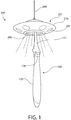
FIG. 1 is a perspective view of an oral care sterilization system according to one embodiment of the present invention including an oral care implement in the form of a toothbrush and sterilization unit; -
FIG. 2 is a perspective view of the toothbrush ofFIG. 1 ; -
FIG. 3 is a front view thereof; -
FIG. 4 is a side view thereof; -
FIG. 5 is a rear view thereof; -
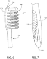
FIG. 6 is an enlarged detail of the head portion of the toothbrush; -
FIG. 7 is an enlarged detail of the handle portion of the toothbrush; -
FIG. 8 is a bottom perspective view showing the toothbrush docked in the sterilization unit; -
FIG. 9 is a top view of the sterilization unit; -
FIG. 10 is a bottom view thereof; -
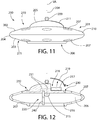
FIG. 11 is a side view thereof; -
FIG. 12 is a side cross-sectional view thereof; -
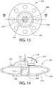
FIG. 13 is a bottom view thereof having an alternative embodiment of a coupling member for mounting the toothbrush to the sterilization unit; -
FIG. 14 is a side cross-sectional view thereof; -
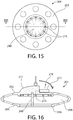
FIG. 15 is bottom view of the sterilization unit having an alternative embodiment of an ultraviolet light source of annular configuration; -
FIG. 16 is a side cross-sectional view thereof; -
FIG. 17 is side view of a mounting stand for supporting the sterilization unit; -
FIG. 18 is a side view of an alternative embodiment of the mounting stand; -
FIG. 19 is a bottom view of an alternative embodiment of the sterilization unit configured with an electric plug for direct insertion into an electrical wall outlet or socket; and -
FIG. 20 is a side view of an alternative embodiment of the sterilization unit. - All drawing are schematic and not necessarily to scale.
- The following description of the preferred embodiment(s) is merely exemplary in nature and is in no way intended to limit the invention, its application, or uses.
- In the description of embodiments disclosed herein, any reference to direction or orientation is merely intended for convenience of description and is not intended in any way to limit the scope of the present invention. Relative terms such as "lower," "upper," "horizontal," "vertical," "above," "below," "up," "down," "top" and "bottom" as well as derivatives thereof (e.g., "horizontally," "downwardly," "upwardly," etc.) should be construed to refer to the orientation as then described or as shown in the drawing under discussion. These relative terms are for convenience of description only and do not require that the apparatus be constructed or operated in a particular orientation unless explicitly indicated as such. Terms such as "attached," "affixed," "connected," "coupled," "interconnected," and similar refer to a relationship wherein structures are secured or attached to one another either directly or indirectly through intervening structures, as well as both movable or rigid attachments or relationships, unless expressly described otherwise.
- As used throughout, ranges are used as shorthand for describing each and every value that is within the range. Any value within the range can be selected as the terminus of the range. In addition, all references cited herein are hereby incorporated by referenced in their entireties. In the event of a conflict in a definition in the present disclosure and that of a cited reference, the present disclosure controls.
- Referring to
FIG. 1 , a non-limiting embodiment of an oralcare sterilization system 200 according to the present disclosure is shown. The system generally includes asterilization unit 201 and an oral care implement, which may be atoothbrush 100 in one non-limiting embodiment. Thesterilization unit 201 includes adocking station 220, which allows a user to removably and releasably secure thetoothbrush 100 to the unit for disinfection, as further described herein. - Referring now to
FIGS. 2-7 ,toothbrush 100 generally includes anelongated body 101 extending from aproximal end 103 to adistal end 102 along a longitudinal axis A-A. Thebody 101 includes afront side 112, opposingrear side 113, and pair of opposinglateral sides 114 extending between the front and rear sides. The longitudinal axis A-A follows the contours and shapes of thetoothbrush body 101 from proximal todistal ends -
Body 101 further comprises ahead portion 110, ahandle portion 120, and aneck portion 121 coupling the handle to head. In certain embodiments,neck portion 121 may be a structure that is narrower in width (measured transversely to longitudinal axis A-A) than thehead portion 110 and shorter in length than thehandle portion 120 for grasping by a user. - The
front side 112 of thehead portion 110 may be substantially planar in one embodiment. Thehead portion 110 comprises a plurality oftooth cleaning elements 111 extending transversely from thefront side 112. The exact types, structure, pattern, orientation and material of thetooth cleaning elements 111 is not limiting of the present invention unless so specified in the claims. As used herein, the term "tooth cleaning elements" is used in a generic sense to refer to any structure or combination of structures that can be used to clean, polish or wipe the teeth and/or soft oral tissue (e.g. tongue, cheek, gums, etc.) through relative surface contact. Common examples of "tooth cleaning elements" include, without limitation, bristle tufts, filament bristles, fiber bristles, nylon bristles, spiral bristles, rubber bristles, elastomeric protrusions, flexible polymer protrusions, combinations thereof and/or structures containing such materials or combinations. Suitable elastomeric materials include any biocompatible resilient material suitable for uses in an oral hygiene apparatus. To provide optimum comfort as well as cleaning benefits, the elastomeric material of the tooth or soft tissue engaging elements may have a hardness property in the range of A8 to A25 Shore hardness. One suitable elastomeric material is styrene-ethylene/butylene-styrene block copolymer (SEBS) manufactured by GLS Corporation. Nevertheless, SEBS material from other manufacturers or other materials within and outside the noted hardness range could be used. - The
tooth cleaning elements 111 of the present invention can be connected to thehead portion 110 in any manner now available or to be developed and is also not limiting of the invention. For example, staples/anchors, in-mold tufting (IMT) or anchor free tufting (AFT) could be used to mount the cleaning elements/tooth engaging elements. In AFT, a plate or membrane is secured to the brush head such as by ultrasonic welding. The bristles extend through the plate or membrane. The free ends of the bristles on one side of the plate or membrane perform the cleaning function. The ends of the bristles on the other side of the plate or membrane are melted together by heat to be anchored in place. Any suitable form of cleaning elements may be used in the broad practice of this invention. Alternatively, the bristles could be mounted to tuft blocks or sections by extending through suitable openings in the tuft blocks so that the base of the bristles is mounted within or below the tuft block. - In certain embodiments, the
head portion 110 may also include a soft tissue cleanser (not shown herein) coupled to or positioned on itsrear side 113. An example of a suitable soft tissue cleanser that may be used with the present invention and positioned on the rear surface of thehead portion 110 is disclosed inU.S. Patent No. 7,143,462, issued December 5, 2006 to the assignee of the present application, the entirety of which is hereby incorporated by reference. In certain embodiments, the soft tissue cleanser may include a plurality of protuberances, which can take the form of elongated ridges, nubs, or combinations thereof. Of course, the invention is not to be so limited and in certain embodiments the oral care implement 100 may not include any soft tissue cleanser. - In the exemplified embodiment, the
head portion 110 is formed integrally with thehandle portion 120 andneck portion 121 as a single unitary structure using a molding, milling, machining, and/or other suitable process. However, in other embodiments thehandle portion 120,neck portion 121, andhead portion 110 may be formed as separate components which are operably connected at a later stage of the manufacturing process by any suitable technique known in the art, including without limitation thermal or ultrasonic welding, a tight-fit assembly, a coupling sleeve, threaded engagement, adhesion, or fasteners. In certain embodiments, the head andneck portions handle portion 120, thereby allowing the head to be replaceable when thetooth cleaning elements 111 have worn. - With continuing reference to
FIGS. 2-7 , thehandle portion 120 is an axially elongated structure extending from theproximal end 103 of thebody 101 to theneck portion 121 that provides a means for grasping and manipulating thetoothbrush 100 during use. Thehandle portion 120 may comprise an ergonomically contouredthumb grip section 122 adjoining theneck portion 121 and afinger grip section 123 adjoining the thumb grip section that is disposed more proximally. Thethumb grip section 122 is located between theneck portion 121 and thefinger grip section 123.Handle portion 120 further defines afront surface 124, an opposingrear surface 125, and two opposing lateral side surfaces 126. Surfaces 124-126 collectively form anouter surface 127 of thehandle portion 120. - In the exemplified embodiment, the
handle portion 120 is generically depicted having various contours for user comfort. More specifically, in the exemplified embodiment thethumb grip section 122 of thehandle portion 120 is a more bulbous diametrically enlarged structure relative to theouter surface 127 of and other portions of thehandle portion 120. Thus,thumb grip section 122 may have a diameter and width measured transversely to longitudinal axis A-A between lateral side surfaces 126 of thehandle portion 120 that is greater than a width of thefinger grip section 123 of the handle portion. Of course, the invention is not to be so limited in all embodiments, and in certain other embodiments thethumb grip section 122 may not have a greater width than the entire or at least portions of thefinger grip section 123. For example, the proximal portion of thefinger grip section 123 may be bulbous shaped and wider than other portions of the finger grip section in addition to or instead of thethumb grip section 122. Thehandle portion 120 can therefore take on a wide variety of shapes, contours and configurations, none of which are limiting of the present invention unless so specified in the claims. - In the exemplified embodiment, the
toothbrush body 101 may be made of a substantially rigid plastic material, such as for example without limitation polymers and copolymers of ethylene, propylene, butadiene, vinyl compounds and polyesters such as polyethylene terephthalate. Of course, the invention is not to be so limited in all embodiments and thehandle portion 120 may be formed with a semi-rigid material. -
Handle portion 120 may further include various surface portions which are formed of a non-slip resiliently flexible material for greater comfort and handling, such as without limitation a thermoplastic elastomer (TPE) affixed over portions of or the entirety of thehandle portion 120 to enhance grip control of the toothbrush during use. For example, parts of thehandle portion 120 that are typically gripped by a user's palm, fingers, and/or thumb during use, such as thefinger grip section 123 andthumb grip section 122, may be partially or totally overmolded with a thermoplastic elastomer or other resilient material to further increase comfort and grip for a user. The TPE may be overmolded onto the more rigid plastic used to form thebody 101 oftoothbrush 100 during the fabrication process. - In the illustrated embodiment, for example, a finger
grip control member 130 formed of the foregoing resilient material may be disposed on parts of the rear andside surfaces handle portion 120 oftoothbrush 100. In one embodiment,thumb grip section 122 of thetoothbrush handle portion 120 may include a thumbgrip control member 128 formed of the resilient material to facilitate gripping the toothbrush.Grip control member 128 may be disposed on thefront surface 124 of the thumb grip section, as shown. - The
sterilization unit 201 of the oralcare sterilization system 200 will now be further described with initial reference toFIGS. 1 and8-12 .Sterilization unit 201 includes a partiallyhollow housing 210 including atop surface 202,bottom surface 203, andperipheral sides 204 therebetween that define a peripheral edge and perimeter of the housing. A downwardlyopen cavity 206 formed in thebottom surface 203 of the housing is configured for insertably receiving at least a part of thebody 101 oftoothbrush 100 therein, as further described herein.Housing 210 defines a vertical centerline or axis VA extending through the geometric centerline of the housing. -
Housing 210 is preferably made of any suitable light-weight material. In one embodiment, the housing is made of suitable substantially rigid plastic material such as for example without limitation polymers and copolymers of ethylene, propylene, butadiene, vinyl compounds and polyesters such as polyethylene terephthalate. Of course, the invention is not to be so limited in all embodiments and thehousing 210 may be formed of other suitable rigid materials or a combination of different types of materials. - To provide the sterilization functionality, the
sterilization unit 201 further includes a sterilization element such as an ultraviolet (UV)light source 215 configured and operable to irradiate thetoothbrush 100 with ultraviolet radiation in the disinfection spectrum (i.e. UV-C) suitable to kill bacterial accumulations on at least thehead portion 110 of the toothbrush body. UVlight source 215 is disposed incavity 206 and accessible viabottom opening 216 formed in thebottom surface 203 of thehousing 210 Any suitable commercially-available UV-C light source may be used, such as for example without limitation least one UV light emitting diode (LED), a UV xenon bulb, or a UV mercury bulb. In one embodiment, a single UV light bulb or LED may be provided if sufficient UV radiation can be generated to disinfect the toothbrush 100 (see, e.g.FIGS. 10 and12 ). The single UV source may be disposed above thetoothbrush head portion 120 when attached to thesterilization unit 201. Lateral placement of the single bulb or LED may also be used. In yet other embodiments, an array of UV light bulbs or LEDs may be provided (see, e.g.FIGS. 15 and 16 ) which are arranged above and/or laterally around thetoothbrush head portion 120 to irradiate the head from a plurality of sides. The array of UV bulbs or LEDs may be arranged in an annular pattern extending a full 360 degrees around thehead portion 120 of the toothbrush in certain implementations as shown. In other embodiments, the UV array may extend in an arc less than 360 degrees around the toothbrush. -
Light source 215 is powered by a suitable electrical power source. The power source may be an on-board power source such as disposable or rechargeable battery orbatteries 217. The batteries may be disposed in abattery compartment 218 formed in a portion of thesterilization unit housing 210. In one embodiment,battery compartment 218 may be disposed in the top portion ofhousing 210 and include a removablebattery compartment cover 219. Cover 219 may be secured tohousing 210 by alocking mechanism 230, which may comprise a resilient tab on the cover which engages a mating slot formed in the housing (as shown) that provides a snap-lock. Other locking mechanisms may of course be used to secure the cover to the housing. Thecover 219 may be arcuately curved in one embodiment to conform to the shape and contour of the portion of the housing where thebattery compartment 218 is located.Battery compartment 218 includes the usual electrical contacts to electrically conduct electrical current from thebatteries 217 to the UVlight source 215 viawiring 231 run through thehousing 210. An on/offpower switch 232 is electrically connected and wired to the power source (battery compartment 218) for turning theUV light source 215 on or off. Theswitch 232 may be mounted at any suitable location on thesterilization unit housing 210. - In other embodiments, the electrical power source may also be a more permanent type power source such as a conventional electric utility power grid supply that provides standard AC line voltage (e.g. 120V or 220V) to the UV
light source 215. An electric cord (wire conductor) 233 having a standard wall outlet electric plug on one end carries the electric current to the UVlight source 215 in the sterilization unit 201 (see, e.g.FIGS. 17 and18 ). A step-down transformer may be provided if required to convert the AC line voltage to DC low voltage power usable by thelight source 215. Such a transformer may be either directly plugged into an available electric wall socket or incorporated in thehousing 210 of thesterilization unit 201. - The
sterilization unit 201 includes adocking station 220 that provides a coupling mechanism configured for releasably attaching and holding thetoothbrush 100 in the unit while thetoothbrush 100 is undergoing sterilization and for storage thereafter. Referring toFIGS. 8-12 , the coupling mechanism may be magnetic in one non-limiting implementation.Docking station 220 in this embodiment includes amagnet 240 which is mounted incavity 206 of thesterilization unit housing 210. The magnet forms a first coupling member.Magnet 240 is accessible through thebottom opening 216 formed in thebottom surface 203 of thehousing 210. The magnet may be mounted proximate to vertical axis VA of thesterilization unit 201 near the center of thecavity 206 as shown, but slightly offset to one side. This allows thetoothbrush 100 to be located along and parallel to the vertical axis VA when mounted in the sterilization unit.Magnet 240 is further located proximate toUV light source 215 to allow thetoothbrush 100 to be properly irradiated with UV radiation from the light source. - In one embodiment,
magnet 240 may be a generally plate-like and flat structure in configuration having a generally rectilinear shape (e.g. rectangular or square). Other polygonal and non-polygonal (e.g. circular, etc.) shapes be used. In alternate embodiments,magnet 240 may have a ring-like annular configuration such asannular magnet 340 shown inFIGS. 13 and 14 .Magnet 340 defines acentral receptacle 341 configured to receive thehead portion 110 oftoothbrush 100 therein. The UVlight source 215 is mounted at the top of thereceptacle 341 for irradiating the toothbrush. Theannular magnet 341 requires less precise placement and insertion of the toothbrush head into the receptacle and engagement with the magnet. Thetoothbrush 100 may have any rotational orientation therefore when coupled to theannular magnet 340. This contrasts to use of theflat magnet 240 in which the toothbrush has a single rotational orientation when properly coupled thereto for sterilization. It will be appreciated that other shapes of magnets may be used. Any suitable type of commercially-available magnet may be used. - The second coupling member of the toothbrush-to-docking station magnetic coupling mechanism is formed by a
magnetic metal element 241 disposed on thetoothbrush 100. Themagnetic metal element 241 may be formed of any suitable ferro- and ferrimagnetic material capable of being magnetically attracted and coupled tomagnet 240 in the sterilizationunit docking station 220. Steel may be used in one non-limiting example; however, other magnetic metals attracted to a magnet by magnetic force may be used. In alternative embodiment, a second magnet may be substituted for magnetic metal. - In one embodiment, the
magnetic metal element 241 is disposed in thehead portion 110 of thetoothbrush body 101. This ensures that when thetoothbrush 100 is mounted tomagnet 240 in thesterilization unit 210, thehead portion 110 is positioned proximate to the UVlight source 215 for optimum sterilization. In one configuration, themagnetic metal element 241 may comprise a thin metal plate of suitable configuration, which is attached to therear side 113 of thetoothbrush head portion 110 oppositefront side 112 containing the tooth cleaning elements. To avoid direct contact of the metal plate with the toothbrush user's mouth, themagnetic metal element 241 may be recessed below the rear surface of therear side 113 oftoothbrush head portion 110 and covered by an overlying material. In one embodiment, the overlyingmaterial 242 may be an elastomeric material as already described herein that is overmolded on thehead portion 110 of thetoothbrush 100. The overlying material is preferably thin and just thick enough to cover themagnetic metal element 241 while still allowing secure magnetic coupling of the toothbrush to themagnet 240 of the sterilizationunit docking station 220. Other types of overlying materials may of course be used. - A method for sterilizing a
toothbrush 100 usingUV sterilization unit 201 will now be briefly described. The user first positions thetoothbrush 100 below thebottom opening 206 of thesterilization unit 201 and rotationally orients thetoothbrush 100 so that therear side 113 of thetoothbrush head portion 110 withmagnetic metal element 241 faces the docking station magnet 240 (i.e.tooth cleaning elements 111 onfront side 112 of the toothbrush facing away from the magnet). The user then raises and vertically inserts thehead portion 110 of thetoothbrush 100 upwards through thebottom opening 216 into theinternal cavity 206 of thesterilization unit housing 210. The user next engages therear side 113 of thetoothbrush head portion 110 with themagnet 240, which magnetically couples the toothbrush thereto due to the magnetic attraction between the magnet andmagnetic metal element 241 disposed in the toothbrush head. Notably,toothbrush 100 is supported in a dangling or suspended manner from thesterilization unit 201 by thehead portion 110 as shown in which thetoothbrush handle portion 120 does not engage a support surface for support. Support for the toothbrush is provided solely by the magnetic coupling mechanism in this embodiment.Toothbrush 100 is held in a substantially upright and vertical position, with some angular deviation being possible depending on the accuracy of the user emplacing the toothbrush in the sterilization unit. With the toothbrush mounted in the sterilization unit, the user may then activate theUV light source 215 to sterilize thehead portion 110 toothbrush via operating the on/offpower switch 232. A timer circuit may be provided to activate theUV light source 215 for a predetermined period of time necessary to sterilize the toothbrush. The timer circuit is electrically coupled to the UVlight source 215 power supply and operable to disconnect power from the light source once the timer times out. UVlight source 215 may stay on continuously during the sterilization period or be pulsed in some embodiments. - When the
toothbrush 100 is coupled to thedocking station 220 of thesterilization unit 201, a majority of the length of thetoothbrush body 101 may remain exposed and extend below thesterilization unit housing 210 as seen inFIG. 1 . In one arrangement, theentire handle portion 120 and part of theneck portion 121 remain below thebottom surface 203 of the housing. It is most important that at least thehead portion 110 and immediately adjoiningneck portion 121 which are typically inserted into the user's mouth when brushing are subjected to irradiation by the UVlight source 215 and sterilized. Accordingly, thehousing 210 need only have a sufficient height in some embodiments to receive the head and adjoining neck portions of the therein for sterilization. - In the present embodiment being described, it bears noting that longitudinal axis A-A of
toothbrush 100 is coaxially aligned with the vertical axis VA of thesterilization unit 201. In other embodiments, thetoothbrush 100 may be mounted off-axis with respect to vertical axis VA. Accordingly, the invention is not limited to a centered toothbrush coupling arrangement to the sterilization unit. - In the foregoing embodiment described, it bears noting that the
magnet 240 is mounted in thesterilization unit 201 and themagnetic metal element 241 is mounted in thetoothbrush 100. However, it will be appreciated by those skilled in the art that this arrangement may be reversed in other embodiments to provide the magnetic coupling mechanism. - Although a magnetic coupling mechanism is described herein for removably coupling the
toothbrush 100 to thesterilization unit 201, other types of coupling may be used such as mechanical couplings including snap lock mechanisms, hangers, or other. Accordingly, the invention is expressly not limited to magnetic coupling mechanisms alone. - Referring now to
FIGS. 1 ,11-12 ,18-19 , thesterilization unit 201 in one embodiment is configured to be hung in a freely suspended manner from an available overhead support.Housing 210 may therefore include a mounting assembly comprising a coupler such aseye hook 209 mounted to thetop surface 202 of thehousing 210 and ahanger 208 connected thereto. Thehanger 208 may be a flexible wire, string, or similar in some implementations as shown. A more rigid metal wire or plastic o hanger may also be used in other embodiments. To maintain thehousing 210 in level orientation, thehook 209 andconnected hanger 208 are preferably coaxially mounted to and aligned with vertical axis VA of thesterilization unit 201 as shown. - In some embodiments, the overhead support may a ceiling of a room. When such a mounting arrangement is not possible or desired, the overhead support may be provided by a mounting
stand 255 comprising abase 250 and attached cantileveredsupport arm 251 as shown inFIGS. 17 and18 .Base 250 has a flat bottom configured to rest on an availablehorizontal support surface 252, such as the counter of a bathroom vanity or cabinet.Arm 251 has portions which extend vertically upwards from the base and laterally outwards to provide clearance for thesterilization unit housing 210.Arm 251 includes abottom end 253 attached tobase 250 and a terminalfree end 254 to which thehanger 208 of thesterilization unit housing 210 is connected.Base 250 has a sufficient width to provide stable mounting for thesterilization unit 201. In embodiments where AC house line voltage is used to power theUV light source 215 as described above, theelectric cord 233 may be routed through the mounting stand to thesterilization unit 201 as shown. In other embodiments where available counter space may be limited, thebase 250 may be omitted and thearm 251 may be configured for direct attachment to an available vertical wall such as via suitable fasteners. - In an alternative embodiment, the
sterilization unit 201 may be configured to be plugged in directly to an available electric wall outlet or socket where AC house line voltage is used to power theUV light source 215. Such a configuration is shown for example inFIG. 19 . Thehousing 210 of thesterilization unit 201 may include a flatperipheral surface 260 which includes an integratedelectric plug 261 with standard prong arrangement to plug the unit into the wall socket (not shown). Thesterilization unit 201 is therefore hung in a cantilevered manner from the wall outlet. Based on the foregoing embodiments, it will be appreciated that numerous mounting variations are possible forsterilization unit 201 and does not limit the invention. - According to another aspect of the invention, the oral
care sterilization system 200 may have a motif that is intended to make the brushing and sterilization experience more fun for younger users. This will motivate these users to adhere to a regular oral care regimen. This is achieved by configuring and/or adorning thetoothbrush 100 andsterilization unit 201 with thematic features sharing a common motif. This combines the concepts of playing and brushing for younger users. - A non-limiting example of an oral care sterilization system having thematic features sharing a common motif is illustrated herein. The motif is extraterrestrials in this case. The
sterilization unit 201 has thematic features which are indicative of a UFO (unidentified flying object). Thehousing 210 has a disk-shaped configuration that resembles a "flying saucer" and thus embodies a thematic feature by configuration. The housing anupper portion 270 andlower portion 271 separated by theperipheral sides 204 or edge. The upper and lower portions may be arcuately curved and convex shaped as shown in one embodiment. A raiseddome 211 is disposed on theupper portion 270, which may conveniently house the battery compartment, controls, wiring, UV light source, and other related functional appurtenances already described above as best shown inFIG. 12 . Theeye hook 209 forhanger 208 may also be mounted to the dome structure. Thelower portion 271 and part of theupper portion 270 define theinternal cavity 206 of thehousing 210 and may therefore be substantially hollow. - To further exemplify the extraterrestrial motif, a plurality of
open ports 207 may be formed through thelower portion 271 and/orupper portion 270 of thesterilization unit housing 210 thereby providing an additional thematic feature. When the UVlight source 215 is activated, the bluish-purple light emitted will glow and shine through theports 207, in addition to through thebottom opening 216. This contributes to replicating an appearance commonly associated with UFOs. In some embodiments, thelight source 215 may be pulsed for effect rather than having a continuous intensity. Theports 207 may be physically open structures in some embodiments, or in other embodiments may include a transparent or translucent window to partially obscure the internal structure of thehousing 210. It will be appreciated that in addition to providing the primary function of sterilizing thetoothbrush 100, thesterilization unit 201 further serves as a night light which is beneficial for younger users. - In addition to the structural features and configuration of the
sterilization unit housing 210 described above which serve as thematic features of the common extraterrestrial motif,housing 210 may further include markings or indicia that further exemplify and comprise the motif. The indicia may be formed by appliques or paint applied to the surface of thehousing 210, or indicia which are integrally formed with and/or embedded via molding and overmolding of the housing. Such indicia may include for example without limitation numerical and alphabetic characters forming words and numbers, graphic or photographic images and designs, or other markings evincing the extraterrestrial motif. Any types of indicia or markings may be therefore be used. - The
toothbrush 100 also includes thematic features sharing the common extraterrestrial motif in this example, which complement the thematic features of thesterilization unit housing 210 described above. Referring toFIGS. 1-4 , the toothbrush thematic features may include anindicia 128 in the form of an extraterrestrial being image applied or embedded in thebody 101 of thetoothbrush 100. The image in this non-limiting example is the head of an extraterrestrial being. In one embodiment, the indicia image may be formed of a resilient elastomeric material overmolded onto the body of the oral care implement and positioned to provide a non-slip gripping surface for the user. The gripping surface may be a thumb grip positioned on the distal-most portion of thetoothbrush handle portion 120 adjacent to theneck portion 121. It will be appreciated that various other indicia and positioning on the toothbrush body may be used instead of or in addition toindicia 128, which demonstrates just one non-limiting example. - It bears noting that
indicia 128 oftoothbrush 100 representing a first thematic feature is not identical to the set of second thematic features of thesterilization unit 201 described above comprising the UFO. However, the first and second thematic features still share the common extraterrestrial motif and are therefore complementary in nature. - When the
toothbrush 100 is magnetically docked in thesterilization unit 201 as shown inFIG. 1 , the common extraterrestrial motif is apparent. Of interest to younger users, theindicia 128 on thetoothbrush handle portion 120 is illuminated by UV light emitted through thebottom opening 216 of thesterilization unit housing 210 which contributes to a positive and fun brushing experience. - If a mounting
stand 255 is to be used and provided, the stand may include a third thematic feature sharing the common extraterrestrial motif with the toothbrush and sterilization unit. An example is shown inFIG. 18 depicting a mountingstand 255 having asupport arm 251 configured as the moon that defines a thematic feature by configuration. Various other typeos of thematic features such as indicia may also be provided in other embodiments. - It will be appreciated that numerous other common motifs may be used for the
sterilization unit 201 andtoothbrush 100; examples of which have already been described herein. Accordingly, the invention is not limited to the extraterrestrial motif described herein for illustrative purposes only. -
FIG. 20 depicts an alternative embodiment of a sterilization unit 201A. This embodiment includes a circumferential array ofdecorative LEDs 300 arranged in an annular pattern or ring along thelateral sides 204 of thesterilization unit housing 210. TheLEDs 300 may be powered by the same power source used to power the UV light source 215 (i.e. battery(ies) or building AC/DC line current). This embodiment illustrates aUSB port 302 that can be used to supply transformed AC/DC low voltage power to the UV light source. In this case,power cord 233 may have a male USB plug which is inserted into the female USB port. USB port may be a regular size or mini-USB type port. Alternatively,USB port 302 may be used to recharge a lithium ion battery if used instead as the power source and is electrically connected to thebattery compartment 218. In other embodiments, theUSB power port 302 may alternatively be used to separately power the ring ofdecorative LEDs 300 separate from powering theUV light source 215. In other embodiments, thedecorative LEDs 300 may be arranged or emplaced in different locations on thehousing 210 of thesterilization unit 201. - While the invention has been described with respect to specific examples including presently preferred modes of carrying out the invention, those skilled in the art will appreciate that there are numerous variations and permutations of the above described systems and techniques. It is to be understood that other embodiments may be utilized and structural and functional modifications may be made without departing from the scope of the present invention. Thus, the spirit and scope of the invention should be construed broadly as set forth in the appended claims.
Claims (15)
- An oral care sterilization system comprising:an oral care implement including an elongated body having a plurality of tooth cleaning elements and a first thematic feature;a sterilization unit including a housing configured for removable attachment of the oral care implement to the sterilization unit, the sterilization unit having a second thematic feature; anda sterilization element disposed in the housing proximate to the oral care implement when attached thereto, the sterilization element arranged and operable to irradiate a head portion of the oral care implement with ultraviolet radiation;wherein the first and second thematic features are complementary and share a common motif.
- The oral care sterilization system according to claim 1, wherein the oral care implement is vertically suspended from the sterilization unit when mounted therein.
- The oral care sterilization system according to claims 1 or 2, wherein the housing includes a shape that defines the second thematic feature and the first thematic feature is an indicia disposed on a body of the oral care implement having a complementary motif to the housing shape, optionally wherein the housing is shaped like a flying saucer and the indicia on the oral care implement is an image of an extraterrestrial being.
- The oral care sterilization system according to claim 3 wherein the indicia on the oral care implement is formed of a resilient elastomeric material overmolded on the body of the oral care implement providing a non-slip gripping surface.
- The oral care sterilization system according to any of claims 1 to 4, wherein the oral care implement is magnetically attached to the housing of the sterilization unit, optionally wherein the oral care implement has a magnetic metal element and the housing of the sterilization unit has a magnet that magnetically and releasably secures the oral care implement to the housing.
- The oral care sterilization system according to any one of claims 1 to 5, wherein the housing defines a downwardly open cavity and a first coupling member, and a head portion of the oral care implement includes a second coupling member, the oral care implement being insertable into the cavity to engage the first and second coupling members for securing the oral care implement to the sterilization unit.
- The oral care sterilization system according to any one of claims 1 to 6, wherein the sterilization element is an ultraviolet light source comprising at least one light emitting diode, a xenon bulb, or a mercury bulb, and further comprising a power source comprised of one or more batteries removably disposed in the housing, the power source configured to provide electric power to the light source.
- The oral care sterilization system according to any one of claims 1 to 7, wherein the housing of the sterilization unit is hung in a suspended manner from a support.
- The oral care sterilization system according to any one of claims 1 to 8, wherein the housing of the sterilization unit includes an integral electrical plug configured for insertion into an electrical wall socket.
- An oral care kit comprising:a toothbrush including an elongated body comprising a longitudinal axis, a distal head portion having a plurality of tooth cleaning elements, a proximal handle portion, the head portion comprising a first coupling member;a sterilization unit including a housing defining a vertical axis, a downwardly open internal cavity, an ultraviolet light source disposed in the cavity, and a second coupling member disposed in the cavity;the toothbrush removably suspended from the sterilization unit via releasable engagement between the first and second coupling members;wherein the ultraviolet light source is arranged and operable to irradiate at least the head portion of the oral care implement with ultraviolet radiation.
- The oral care kit according to claim 10, wherein the sterilization unit is hung in a suspended manner from an overhead support.
- The oral care kit according to any one of claims 10 to 11, wherein the housing has a shape defining a flying saucer that defines a first thematic feature and the toothbrush has an indicia of an extraterrestrial alien that defines a second thematic feature, the first and second thematic features defining a common motif that is extraterrestrials, optionally wherein the indicia on the toothbrush is formed of a resilient elastomeric material overmolded on the body of the toothbrush positioned to provide a non-slip thumb gripping surface.
- The oral care kit according to any one of claims 10 to 12, wherein the first coupling member on the toothbrush is a magnetic metal element and the second coupling member of the sterilization unit is a magnet that magnetically and releasably secures the toothbrush to the sterilization unit, optionally wherein the magnetic metal element is recessed in the body of the toothbrush and covered by a thin layer of an overlying elastomeric material overmolded onto the body of the toothbrush.
- A method for sterilizing an oral care implement, the method comprising:positioning a toothbrush below a bottom opening of an ultraviolet sterilization unit;raising the toothbrush vertically upwards towards the bottom opening;inserting a head portion of the toothbrush through the bottom opening and into an internal cavity of the sterilization unit; andengaging a first coupling member on the toothbrush with a second coupling member in the sterilization unit.
- The method according to claim 14, wherein the toothbrush is hung from the sterilization unit in a suspended manner.
Applications Claiming Priority (1)
| Application Number | Priority Date | Filing Date | Title |
|---|---|---|---|
| CN201710804248.7A CN109464684A (en) | 2017-09-07 | 2017-09-07 | Oral care implement disinfection system |
Publications (1)
| Publication Number | Publication Date |
|---|---|
| EP3476249A1 true EP3476249A1 (en) | 2019-05-01 |
Family
ID=63528541
Family Applications (1)
| Application Number | Title | Priority Date | Filing Date |
|---|---|---|---|
| EP18193081.9A Withdrawn EP3476249A1 (en) | 2017-09-07 | 2018-09-07 | Oral care implement sterilization system |
Country Status (3)
| Country | Link |
|---|---|
| US (1) | US20190070326A1 (en) |
| EP (1) | EP3476249A1 (en) |
| CN (1) | CN109464684A (en) |
Families Citing this family (8)
| Publication number | Priority date | Publication date | Assignee | Title |
|---|---|---|---|---|
| US10786339B1 (en) * | 2019-07-12 | 2020-09-29 | Sdc U.S. Smilepay Spv | Hygienic brush |
| US11786622B2 (en) * | 2020-05-08 | 2023-10-17 | Ultra-Violet Solutions, Llc | Far UV-C light apparatus |
| US11326745B2 (en) * | 2020-06-30 | 2022-05-10 | Xiamen Leedarson Lighting Co. Ltd | LED light tube apparatus |
| US11744914B2 (en) * | 2020-07-15 | 2023-09-05 | John R. Wyss | Projection of germicidal ultra-violet light by edgelit substrate |
| US11786619B2 (en) * | 2020-07-16 | 2023-10-17 | Troy-CSL Lighting Inc. | Ultraviolet radiation lighting device |
| US11819116B2 (en) * | 2020-07-17 | 2023-11-21 | Robert Griffith | Magnetically levitating sterilizing toothbrush holder |
| KR102577553B1 (en) * | 2020-11-19 | 2023-09-13 | 주식회사 헬로우미스터리 | Toothbrush sterilizer with sterilization and drying functions |
| WO2023049437A1 (en) * | 2021-09-27 | 2023-03-30 | As America, Inc. | Bath vanity assembly |
Citations (2)
| Publication number | Priority date | Publication date | Assignee | Title |
|---|---|---|---|---|
| WO2001028396A1 (en) * | 1999-10-22 | 2001-04-26 | A Shin Corporation | Tooth-brushing time announcing device |
| US7143462B2 (en) | 2002-09-20 | 2006-12-05 | Colgate-Palmolive Company | Oral care implement |
Family Cites Families (10)
| Publication number | Priority date | Publication date | Assignee | Title |
|---|---|---|---|---|
| US4950902A (en) * | 1987-03-03 | 1990-08-21 | Ritter Charles H | Toothbrush sterilizer with automatic control and method |
| US8695148B2 (en) * | 2002-08-09 | 2014-04-15 | Colgate-Palmolive Company | Toothbrush |
| US20070295916A1 (en) * | 2006-06-23 | 2007-12-27 | David Isidore Reuben | Toothbrush Head Sanitizing Cap with Built-In Ultraviolet LED. |
| KR100960623B1 (en) * | 2009-06-08 | 2010-06-07 | 박정규 | Portable toothbrush disinfector |
| US20120112018A1 (en) * | 2010-11-05 | 2012-05-10 | Heather Jayne Barry | Magnetic-electric toothbrush holder |
| US9801965B2 (en) * | 2013-03-18 | 2017-10-31 | Sensor Electronic Technology, Inc. | Ultraviolet disinfection case |
| EP2896409B1 (en) * | 2014-01-15 | 2022-10-05 | DC & BV France Holding SAS | A device for diffusing a compound |
| CN205125434U (en) * | 2015-09-16 | 2016-04-06 | 深圳市福田区青少年科技教育协会 | Toothbrush can suspend |
| CN205359330U (en) * | 2016-01-25 | 2016-07-06 | 王玉 | Composite set of toothbrush and toothbrush case |
| CN205913281U (en) * | 2016-03-30 | 2017-02-01 | 淮南市唐山镇第三建材厂 | Take toothbrush to place toothbrush subassembly of box |
-
2017
- 2017-09-07 CN CN201710804248.7A patent/CN109464684A/en active Pending
-
2018
- 2018-09-07 EP EP18193081.9A patent/EP3476249A1/en not_active Withdrawn
- 2018-09-07 US US16/124,267 patent/US20190070326A1/en not_active Abandoned
Patent Citations (2)
| Publication number | Priority date | Publication date | Assignee | Title |
|---|---|---|---|---|
| WO2001028396A1 (en) * | 1999-10-22 | 2001-04-26 | A Shin Corporation | Tooth-brushing time announcing device |
| US7143462B2 (en) | 2002-09-20 | 2006-12-05 | Colgate-Palmolive Company | Oral care implement |
Also Published As
| Publication number | Publication date |
|---|---|
| US20190070326A1 (en) | 2019-03-07 |
| CN109464684A (en) | 2019-03-15 |
Similar Documents
| Publication | Publication Date | Title |
|---|---|---|
| EP3476249A1 (en) | Oral care implement sterilization system | |
| US4235253A (en) | Electric dental flosser | |
| US4399582A (en) | Modular interproximal toothbrush system | |
| US5160194A (en) | Toothbrush with externally illuminated bristles | |
| EP3076825B1 (en) | Short wavelength visible light-emitting toothbrush with an electronic signal interlock control | |
| CN106535711B (en) | Electric toothbrush | |
| US20190000601A1 (en) | Bristle-Less Teeth Cleaning Device with Automatic Gel Dispensing for Combined Mechanical and Chemical Activation | |
| US20090229062A1 (en) | Dental hygiene device | |
| US20080052845A1 (en) | Cylindrical dual rotating electric toothbrush | |
| EP3528853B1 (en) | Oral care implement sanitization system | |
| US10869542B2 (en) | Dental brush | |
| BR112020009006A2 (en) | appliance for oral hygiene | |
| US20200253465A1 (en) | Lighted Bite Block | |
| KR102119588B1 (en) | Electric Powered Toothbrush With Massaging Deveice For Teethridge | |
| US20100319149A1 (en) | Infant toothbrush | |
| CN112423622A (en) | Oral care system including an oral care implement and a tracking attachment, tracking attachment therefor, and method of assembly | |
| JP2008295994A (en) | System toothbrush with illumination | |
| KR20150057082A (en) | Mouthpiece type electric toothbrush | |
| US20230181301A1 (en) | Rotating toothbrush | |
| JP2006068361A (en) | Toothbrush | |
| KR102176455B1 (en) | A functional toothbrush | |
| MXPA05006554A (en) | Power toothbrush with unique handle. | |
| EP0130252B1 (en) | Modular interproximal toothbrushes | |
| BR112021001489A2 (en) | electric oral hygiene instrument including a tracking module and tracking module | |
| KR101660177B1 (en) | A Multifunctional LED toothbrush which leads to the right brushing habit |
Legal Events
| Date | Code | Title | Description |
|---|---|---|---|
| PUAI | Public reference made under article 153(3) epc to a published international application that has entered the european phase |
Free format text: ORIGINAL CODE: 0009012 |
|
| STAA | Information on the status of an ep patent application or granted ep patent |
Free format text: STATUS: THE APPLICATION HAS BEEN PUBLISHED |
|
| AK | Designated contracting states |
Kind code of ref document: A1 Designated state(s): AL AT BE BG CH CY CZ DE DK EE ES FI FR GB GR HR HU IE IS IT LI LT LU LV MC MK MT NL NO PL PT RO RS SE SI SK SM TR |
|
| AX | Request for extension of the european patent |
Extension state: BA ME |
|
| STAA | Information on the status of an ep patent application or granted ep patent |
Free format text: STATUS: REQUEST FOR EXAMINATION WAS MADE |
|
| 17P | Request for examination filed |
Effective date: 20191031 |
|
| RBV | Designated contracting states (corrected) |
Designated state(s): AL AT BE BG CH CY CZ DE DK EE ES FI FR GB GR HR HU IE IS IT LI LT LU LV MC MK MT NL NO PL PT RO RS SE SI SK SM TR |
|
| STAA | Information on the status of an ep patent application or granted ep patent |
Free format text: STATUS: EXAMINATION IS IN PROGRESS |
|
| 17Q | First examination report despatched |
Effective date: 20220113 |
|
| STAA | Information on the status of an ep patent application or granted ep patent |
Free format text: STATUS: THE APPLICATION IS DEEMED TO BE WITHDRAWN |
|
| 18D | Application deemed to be withdrawn |
Effective date: 20230401 |