EP3476194A1 - Système et procédé pour surveiller des concentrations de vapeur - Google Patents
Système et procédé pour surveiller des concentrations de vapeur Download PDFInfo
- Publication number
- EP3476194A1 EP3476194A1 EP18202951.2A EP18202951A EP3476194A1 EP 3476194 A1 EP3476194 A1 EP 3476194A1 EP 18202951 A EP18202951 A EP 18202951A EP 3476194 A1 EP3476194 A1 EP 3476194A1
- Authority
- EP
- European Patent Office
- Prior art keywords
- sensor
- vapor
- concentration
- soil
- agricultural implement
- Prior art date
- Legal status (The legal status is an assumption and is not a legal conclusion. Google has not performed a legal analysis and makes no representation as to the accuracy of the status listed.)
- Granted
Links
- 238000000034 method Methods 0.000 title claims abstract description 20
- QGZKDVFQNNGYKY-UHFFFAOYSA-N Ammonia Chemical compound N QGZKDVFQNNGYKY-UHFFFAOYSA-N 0.000 claims abstract description 97
- 239000002689 soil Substances 0.000 claims abstract description 49
- 229910021529 ammonia Inorganic materials 0.000 claims abstract description 18
- 238000012544 monitoring process Methods 0.000 claims abstract description 13
- 230000008569 process Effects 0.000 claims abstract description 5
- IJGRMHOSHXDMSA-UHFFFAOYSA-N Atomic nitrogen Chemical compound N#N IJGRMHOSHXDMSA-UHFFFAOYSA-N 0.000 claims description 20
- 229910052757 nitrogen Inorganic materials 0.000 claims description 10
- 238000005259 measurement Methods 0.000 claims description 8
- 230000003287 optical effect Effects 0.000 claims description 3
- 239000007789 gas Substances 0.000 claims description 2
- 230000004807 localization Effects 0.000 claims description 2
- 230000005855 radiation Effects 0.000 claims description 2
- 206010013496 Disturbance in attention Diseases 0.000 claims 2
- 238000003384 imaging method Methods 0.000 claims 1
- 229910000069 nitrogen hydride Inorganic materials 0.000 description 28
- 239000000463 material Substances 0.000 description 14
- 235000015097 nutrients Nutrition 0.000 description 9
- 241000196324 Embryophyta Species 0.000 description 7
- 239000011364 vaporized material Substances 0.000 description 7
- 239000003337 fertilizer Substances 0.000 description 6
- 238000000926 separation method Methods 0.000 description 6
- 239000003570 air Substances 0.000 description 5
- 238000004891 communication Methods 0.000 description 4
- 238000010586 diagram Methods 0.000 description 4
- 239000000126 substance Substances 0.000 description 4
- 238000012545 processing Methods 0.000 description 3
- 240000008042 Zea mays Species 0.000 description 2
- 235000002017 Zea mays subsp mays Nutrition 0.000 description 2
- 239000012080 ambient air Substances 0.000 description 2
- 230000008901 benefit Effects 0.000 description 2
- 230000009977 dual effect Effects 0.000 description 2
- 239000000417 fungicide Substances 0.000 description 2
- 239000000618 nitrogen fertilizer Substances 0.000 description 2
- 238000005070 sampling Methods 0.000 description 2
- 238000011282 treatment Methods 0.000 description 2
- XLYOFNOQVPJJNP-UHFFFAOYSA-N water Substances O XLYOFNOQVPJJNP-UHFFFAOYSA-N 0.000 description 2
- 229910019142 PO4 Inorganic materials 0.000 description 1
- 235000005824 Zea mays ssp. parviglumis Nutrition 0.000 description 1
- 235000016383 Zea mays subsp huehuetenangensis Nutrition 0.000 description 1
- 239000000642 acaricide Substances 0.000 description 1
- 238000013459 approach Methods 0.000 description 1
- 238000007664 blowing Methods 0.000 description 1
- 230000001413 cellular effect Effects 0.000 description 1
- 235000013339 cereals Nutrition 0.000 description 1
- 230000008859 change Effects 0.000 description 1
- 150000001875 compounds Chemical class 0.000 description 1
- 235000005822 corn Nutrition 0.000 description 1
- 230000008021 deposition Effects 0.000 description 1
- 238000013461 design Methods 0.000 description 1
- 230000000694 effects Effects 0.000 description 1
- 238000009313 farming Methods 0.000 description 1
- 230000004720 fertilization Effects 0.000 description 1
- 238000001914 filtration Methods 0.000 description 1
- 230000000855 fungicidal effect Effects 0.000 description 1
- 230000036541 health Effects 0.000 description 1
- 230000002363 herbicidal effect Effects 0.000 description 1
- 239000004009 herbicide Substances 0.000 description 1
- 239000007788 liquid Substances 0.000 description 1
- 235000009973 maize Nutrition 0.000 description 1
- 238000004519 manufacturing process Methods 0.000 description 1
- 230000007246 mechanism Effects 0.000 description 1
- 238000012986 modification Methods 0.000 description 1
- 230000004048 modification Effects 0.000 description 1
- 239000000575 pesticide Substances 0.000 description 1
- NBIIXXVUZAFLBC-UHFFFAOYSA-K phosphate Chemical compound [O-]P([O-])([O-])=O NBIIXXVUZAFLBC-UHFFFAOYSA-K 0.000 description 1
- 239000010452 phosphate Substances 0.000 description 1
- 238000001556 precipitation Methods 0.000 description 1
- 230000009467 reduction Effects 0.000 description 1
- 230000004044 response Effects 0.000 description 1
- 238000007789 sealing Methods 0.000 description 1
- 230000011664 signaling Effects 0.000 description 1
- 239000004016 soil organic matter Substances 0.000 description 1
- 239000007921 spray Substances 0.000 description 1
- 230000007704 transition Effects 0.000 description 1
- 238000009834 vaporization Methods 0.000 description 1
- 230000008016 vaporization Effects 0.000 description 1
Images


Classifications
-
- A—HUMAN NECESSITIES
- A01—AGRICULTURE; FORESTRY; ANIMAL HUSBANDRY; HUNTING; TRAPPING; FISHING
- A01C—PLANTING; SOWING; FERTILISING
- A01C21/00—Methods of fertilising, sowing or planting
- A01C21/007—Determining fertilization requirements
-
- A—HUMAN NECESSITIES
- A01—AGRICULTURE; FORESTRY; ANIMAL HUSBANDRY; HUNTING; TRAPPING; FISHING
- A01B—SOIL WORKING IN AGRICULTURE OR FORESTRY; PARTS, DETAILS, OR ACCESSORIES OF AGRICULTURAL MACHINES OR IMPLEMENTS, IN GENERAL
- A01B49/00—Combined machines
- A01B49/04—Combinations of soil-working tools with non-soil-working tools, e.g. planting tools
- A01B49/06—Combinations of soil-working tools with non-soil-working tools, e.g. planting tools for sowing or fertilising
-
- A—HUMAN NECESSITIES
- A01—AGRICULTURE; FORESTRY; ANIMAL HUSBANDRY; HUNTING; TRAPPING; FISHING
- A01C—PLANTING; SOWING; FERTILISING
- A01C21/00—Methods of fertilising, sowing or planting
- A01C21/005—Following a specific plan, e.g. pattern
-
- A—HUMAN NECESSITIES
- A01—AGRICULTURE; FORESTRY; ANIMAL HUSBANDRY; HUNTING; TRAPPING; FISHING
- A01C—PLANTING; SOWING; FERTILISING
- A01C23/00—Distributing devices specially adapted for liquid manure or other fertilising liquid, including ammonia, e.g. transport tanks or sprinkling wagons
- A01C23/007—Metering or regulating systems
-
- A—HUMAN NECESSITIES
- A01—AGRICULTURE; FORESTRY; ANIMAL HUSBANDRY; HUNTING; TRAPPING; FISHING
- A01C—PLANTING; SOWING; FERTILISING
- A01C23/00—Distributing devices specially adapted for liquid manure or other fertilising liquid, including ammonia, e.g. transport tanks or sprinkling wagons
- A01C23/02—Special arrangements for delivering the liquid directly into the soil
- A01C23/023—Special arrangements for delivering the liquid directly into the soil for liquid or gas fertilisers
- A01C23/024—Special arrangements for delivering the liquid directly into the soil for liquid or gas fertilisers for ammonia
-
- G—PHYSICS
- G01—MEASURING; TESTING
- G01N—INVESTIGATING OR ANALYSING MATERIALS BY DETERMINING THEIR CHEMICAL OR PHYSICAL PROPERTIES
- G01N33/00—Investigating or analysing materials by specific methods not covered by groups G01N1/00 - G01N31/00
- G01N33/0004—Gaseous mixtures, e.g. polluted air
- G01N33/0009—General constructional details of gas analysers, e.g. portable test equipment
- G01N33/0027—General constructional details of gas analysers, e.g. portable test equipment concerning the detector
- G01N33/0036—Specially adapted to detect a particular component
- G01N33/0054—Specially adapted to detect a particular component for ammonia
-
- G—PHYSICS
- G01—MEASURING; TESTING
- G01N—INVESTIGATING OR ANALYSING MATERIALS BY DETERMINING THEIR CHEMICAL OR PHYSICAL PROPERTIES
- G01N33/00—Investigating or analysing materials by specific methods not covered by groups G01N1/00 - G01N31/00
- G01N33/24—Earth materials
-
- G01N33/245—
-
- G—PHYSICS
- G08—SIGNALLING
- G08B—SIGNALLING OR CALLING SYSTEMS; ORDER TELEGRAPHS; ALARM SYSTEMS
- G08B21/00—Alarms responsive to a single specified undesired or abnormal condition and not otherwise provided for
- G08B21/18—Status alarms
- G08B21/182—Level alarms, e.g. alarms responsive to variables exceeding a threshold
-
- B—PERFORMING OPERATIONS; TRANSPORTING
- B64—AIRCRAFT; AVIATION; COSMONAUTICS
- B64C—AEROPLANES; HELICOPTERS
- B64C39/00—Aircraft not otherwise provided for
- B64C39/02—Aircraft not otherwise provided for characterised by special use
- B64C39/024—Aircraft not otherwise provided for characterised by special use of the remote controlled vehicle type, i.e. RPV
-
- B—PERFORMING OPERATIONS; TRANSPORTING
- B64—AIRCRAFT; AVIATION; COSMONAUTICS
- B64U—UNMANNED AERIAL VEHICLES [UAV]; EQUIPMENT THEREFOR
- B64U2101/00—UAVs specially adapted for particular uses or applications
-
- B—PERFORMING OPERATIONS; TRANSPORTING
- B64—AIRCRAFT; AVIATION; COSMONAUTICS
- B64U—UNMANNED AERIAL VEHICLES [UAV]; EQUIPMENT THEREFOR
- B64U2101/00—UAVs specially adapted for particular uses or applications
- B64U2101/40—UAVs specially adapted for particular uses or applications for agriculture or forestry operations
-
- Y—GENERAL TAGGING OF NEW TECHNOLOGICAL DEVELOPMENTS; GENERAL TAGGING OF CROSS-SECTIONAL TECHNOLOGIES SPANNING OVER SEVERAL SECTIONS OF THE IPC; TECHNICAL SUBJECTS COVERED BY FORMER USPC CROSS-REFERENCE ART COLLECTIONS [XRACs] AND DIGESTS
- Y02—TECHNOLOGIES OR APPLICATIONS FOR MITIGATION OR ADAPTATION AGAINST CLIMATE CHANGE
- Y02A—TECHNOLOGIES FOR ADAPTATION TO CLIMATE CHANGE
- Y02A50/00—TECHNOLOGIES FOR ADAPTATION TO CLIMATE CHANGE in human health protection, e.g. against extreme weather
- Y02A50/20—Air quality improvement or preservation, e.g. vehicle emission control or emission reduction by using catalytic converters
Definitions
- the present disclosure generally relates to a system and method for monitoring vapor concentrations associated with an agricultural implement.
- ammonia is a commercially available source of nitrogen fertilizer which helps plants grow; therefore, is widely used in the commercial production of crops like maize or corn.
- NH3 anhydrous ammonia
- ammonia can be released into the atmosphere during the application process, resulting in a difficult and, at times, severe reduction of yields for crop during a growing season. Therefore, there is a need for accurate level measurement of ammonia.
- ammonia has a distinct odor which may be detected by a human operator.
- operator cab air filtration and wind dissipation of NH3 vapor may result in the operator not accurately gauging the NH3 escape or missing it altogether.
- NH3 vapor is much colder than ambient air. As it escapes, it causes water in the air to condense, forming a visible cloud. This method is also unreliable in that it requires certain relationships between NH3 and air temperature as well as humidity. Wind may also disperse the vapor and water cloud, making it hard to gage the amount ofNH3 escaping.
- NH3 meters can provide the gross amount of nitrogen applied to the soil, the net amount cannot be determined without an accurate measure of NH3 lost to the atmosphere at application. In the least, there still exists a need for detecting and reporting excessive loss of NH3 to the air. Insufficient nitrogen fertilization can result in reduced crop yield.
- a sensor system for monitoring vapor concentrations that is associated with an agricultural implement.
- the sensor system can comprise a first sensor coupled to a support structure that is configured to sense a concentration of at least one component of a vapor sample emitted from the soil, where the vapor sample is associated with the dispensed ammonia.
- a controller is communicatively coupled to the first sensor. The controller is configured to receive and process output signals generated by the first sensor to determine an amount of the concentration of the at least one component that is lost during emission, and if the loss exceeds a certain threshold level, an alert is displayed or communicated to an operator of the implement.
- an agricultural apparatus 120 having a sensor system 100 incorporated therein is shown according to an embodiment.
- the agricultural apparatus 120 can include an agricultural vehicle 125 that is arranged to tow an agricultural implement 124 across a worksite 155.
- the agricultural implement 124 can comprise a plurality of ground engaging elements 114 attached to a frame 122.
- the plurality of ground engaging elements 114 can be mechanically coupled to the agricultural implement 124 and can be arranged to extend downwardly from the agricultural implement 124 to perform soil cultivating tasks such as creating openings (e.g., holes, slivers, slices, trenches or furrows) in the soil 150 ofworksite 155.
- the ground engaging elements 114 can include disk harrows, coulters, opener disks, shanks, or other suitable elements, such as opener disks that are used to open the soil for dispensing ammonia or fertilizer in association with the applicator unit 126.
- an applicator unit 126 can be removably coupled, e.g., attached behind or underneath, the agricultural implement 124 with respect to the direction of travel of the agricultural vehicle 125.
- the applicator unit 126 can include a plurality of applicator devices 128 (e.g., nozzles or nutrient knives) that are arranged proximate the ground engaging elements 114 to direct crop input materials or other materials (e.g., anhydrous ammonia, nitrogen, fertilizer, fungicides, nutrients or any combination of crop inputs) into the soil 150 simultaneously as it is being prepared or cultivated.
- the applicator devices 128 comprise nutrient knives
- the nutrient knives alone or together with an opener or opener disk, may create a furrow or groove in the soil for accepting the ammonia or nitrogen, whereas the closer, serrated wheels, or other trailing devices 107 cover the furrow with soil.
- the applicator devices 128 can include tubular, conical, funnel-shaped, syringe or other suitable dispenser shapes that are configured to accurately apply the crop input materials to small areas (e.g. within approximately 1-2 inches of a desired location).
- one or more applicator units 126 can be attached to the rear of the agricultural vehicle 110, either in the lateral direction (e.g. perpendicular to direction of travel) or in series such as when there are multiple types of nutrients that are not mixed together.
- the applicator unit 126 can be arranged to follow a field planter or seeder or no-till air drill (not shown) that is configured to perform a task such as putting seeds into selected positions in rows of soil and covering the seeds with soil. In this configuration, the subsequent applicator unit 126 releases or sprays crop inputs, ammonia, or other compounds near the seeds in a region adjacent to where the seeds are planted.
- an application system 130 can be arranged to trail rearward of the agricultural vehicle 125 and the agricultural implement 124 as shown in FIG. 1 . In other embodiments, the application system 130 can be arranged on the agricultural vehicle 125 forward of the agricultural implement 124.
- the application system 130 can comprise a reservoir 132 (e.g., a tank or nurse tank) having a plurality of dispensing elements 134 coupled thereto that are arranged to supply the crop input materials to each of the applicator devices 128.
- the reservoir 132 can contain pressurized ammonia, anhydrous ammonia (NH 3 ), or other suitable materials, which can be selected based on a desired farming application.
- the application system 130 can comprise an additional reservoir with corresponding dispensing elements 134 that is configured to supply a secondary crop input such as a fungicide, pesticide, herbicide, miticide, or other crop treatments.
- the sensor system 100 can be arranged on or proximate the agricultural implement 124.
- the sensor system 100 can comprise a support structure 102, a first sensor 104 arranged on the support structure 102, a second sensor 106 arranged on a respective ground engaging element 114, and a controller 108 communicatively coupled to the first and second sensors 104, 106.
- the support structure 102 can comprise a support arm 103 removably or fixedly coupled to the agricultural implement 124 that is arranged to extend backwards and away from the agricultural implement 124 ( FIG. 1 ), but may vary in other embodiments.
- the length of arm 103 illustrated in FIG. 1 is not necessarily scaled with respect to the other elements of FIG.
- the support structure 102 can comprise an unmanned aerial vehicle 218, which can be coupled to or arranged to aerially suspend proximate the agricultural implement 124 as will be discussed in further detail with reference to FIG. 3 .
- the first sensor 104 can comprise one or more sensors mounted on the support structure 102 proximate a vapor emission area, such as above, near or behind the trailing ground engaging elements 114.
- the first sensor 104 can be pivoted on arm 103 to be readily located or re-located anywhere near the anhydrous NH3 source as conditions change or a need arises.
- the first sensor 104 can be configured to sense a concentration of at least one component of a vapor sample emitted from the soil 150 as the crop input materials are applied by the applicator devices 128.
- the first sensor 104 can comprise a variety of sensors capable of measuring vapor concentrations, such as, for example, piezoelectric sensors, ultrasonic sensors, infrared sensors, acoustic sensors, laser spectrometers, non-equilibrium electrochemical principal, and other suitable sensor devices, or combinations thereof.
- an optional second sensor 106 may be used on the implement mounted on a pole or support extending above the trailing device.
- the optional second sensor 106 may include a soil attribute sensor, which can be arranged to look downward at the soil without contact with the soil or engage with the soil 150 to sense one or more attributes of a field or a crop over which the agricultural vehicle 112 is traveling.
- the second sensor 106 can be configured to sense a variety of soil and crop-related properties such as, soil type, soil moisture, soil temperature, bulk soil density, soil organic matter, soil cover, residue density, crop type, weed presence, weed type, plant size, plant height, plant health, plant vigor, chemical presence, chemical distribution, or combinations thereof.
- the second sensor 106 can be arranged above ground and can include, but is not limited to one or more of the following sensors: cameras, infrared cameras or other infrared sensors, video cameras, stereo cameras, optical sensors, LIDAR sensors, or structured light systems. Additionally, in other embodiments, the second sensor 106 can be arranged for in-ground measuring of the various soil and crop-related properties and can also include one or more of the aforementioned sensors.
- the controller 108 can be arranged locally on the support structure (e.g., when the unmanned vehicle is used) or the agricultural vehicle 125. Additionally, in other embodiments, the controller 108 can be arranged remotely at a central data processing center.
- the controller 108 may include a microprocessor, microcontroller or other suitable programmable circuitry that is adapted to perform data processing and/or system control operations. For example, based on the measured sensor data received by each of the first and sensors 104, 106, the controller 108 can be configured to generate an operator alert, via the user interface module 506 (in FIG. 6 ), in response to a detected sensor concentration that exceeds a certain threshold level. In some embodiments, first and second sensors 104, 106 may communicate directly with each other.
- FIGS. 1-2 are provided merely for illustrative and exemplary purposes and are in no way are intended to limit the present disclosure or its applications.
- the arrangement and/or structural configuration of sensor system 100 can and will vary according to design and/or specification requirements.
- one or more additional first or sensors 104, 106 can be used to measure concentrations of other vapor materials, other soil or crop-related properties, as well as to provide zone specific measurements.
- the support structure 102 can comprise a plurality of unmanned aerial vehicles deployed near the agricultural implement 124 that are arranged to cover a specific zone or portion of the total vapor concentration area of interest.
- the plurality of unmanned aerial vehicles could also be deployed to increase the frequency in which a spatial zone is measured.
- Sensor system 200 is substantially to sensor system 100, however, sensor system 200 provides for improved measurement accuracy through the use of multiple sensor arrangements for the first sensor 104.
- the first sensor 204 can be collectively arranged on both a support arm 103 and an unmanned aerial vehicle 203.
- each of the first sensors 204 can be configured to simultaneously collect sensor data related to NH3 concentrations as the agricultural apparatus 120 travels over the worksite 155.
- the unmanned aerial vehicle 203 can be arranged to fly in proximity to the agricultural apparatus 120, and utilizing the first sensor 104, can sense and monitor vapors (i.e., NH3) being emitted from the soil as the crop material is being applied to soil via the applicator devices 128.
- vapors i.e., NH3
- the unmanned aerial vehicle 203 can comprise onboard processing/power components (not shown) and a propulsion system 206 that allows for the unmanned aerial vehicle 203 to be autonomously or operator controlled, and allows for the vehicle 125 to communicate wirelessly with the agricultural apparatus 120.
- the propulsion system 206 and the onboard processing components can be used to control the direction, height, attitude, speed, and other characteristics of the unmanned aerial vehicle 203.
- the unmanned aerial vehicle 203 can be optionally coupled directly to the agricultural apparatus 120 via a tether link 210 as shown in FIG. 3 .
- the unmanned aerial vehicle 203 can be coupled to agricultural implement 124, the agricultural vehicle 125, or the reservoir 132 by the tether link 210, which provides power and communication links from the agricultural apparatus 120 to unmanned aerial vehicle 203.
- the unmanned aerial vehicle 203 can also comprise an onboard positioning system that provides geographical information to indicate the relative positions of agricultural apparatus 120 and unmanned aerial vehicle 203.
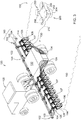
- each ground engaging assembly 314 e.g., a row unit
- each ground engaging assembly 314 can comprise a hopper 310 coupled to a beam assembly 302 that is arranged to supply non-aqueous or non-vaporized crop input materials such as seeds.
- An inlet port 306 of a seed metering device 308 is arranged between the hopper 310 and the second outlet 320.
- a first support member 304 can be coupled to or integral with the frame 322.
- the first support member 304 extend downward from the frame 322.
- a ground engaging disc 301 is supported by or from the first support member 304.
- the ground engaging disc 301 is rotatable with respect the first support member 304; the ground engaging disc 301 may be mounted to the first support member 304 via radial bearing or shaft 312 at a hub of the ground engaging disc 301.
- the ground engaging disc 301 may be fixed or non-rotating with respect to the first support member 304.
- the applicator device 328 can be arranged proximate the ground engaging disc 301 and can track or follow a path of the ground engaging disc 301. As depicted, the applicator device 328 or sharp, pointed member may be connected to or extend from the first support member 304. As illustrated the applicator device 328 (applicator device 328) has a pointed leading edge 324 for forming or carving a groove in the soil 150.
- the applicator device 328 may comprise a first conduit or tube 318 that terminates a first outlet 321 (e.g., treatment opening) for directing nitrogen, ammonia or other nutrient into the soil that the applicator device 328 can displace after the opener.
- a reservoir such as reservoir 132
- at least one of the dispensing elements 334 is connected to the first tube 318 for delivery of NH3, nutrients, nitrogen, fertilizer or other crop input materials from a reservoir.
- the applicator device 328 can comprise a second conduit or tube 316 that terminates in a second outlet 320 for seed deposition into the soil 150 within or spaced apart from the groove by a vertical separation between the first outlet 321 and the second outlet 320.
- the first outlet 321 and the second outlet 320 have one or more of the following separations: a lateral separation, a vertical separation and longitudinal separation, wherein seed and nutrients may be applied simultaneously to the soil consistent with the separations.
- the applicator device 328 can comprise a dual tube arrangement (not shown) that is arranged separate from the seed tube which allows for fertilizer to be applied simultaneously with smaller grain seeds.
- the dual tube arrangement can comprise a first tube that is configured to supply a first fertilizer such as anhydrous ammonia, and a second tube that is configured to supply a second fertilizer such as ammoniated phosphate.
- the crop material can include a material that quickly transitions from liquid to a vaporized material 407 at normal outdoor temperatures, which, in this example, the vaporized material 407 includes anhydrous ammonia (i.e., NH 3 ).
- a three dimensional plume 427 i.e., a vapor concentration area is formed by the emissions of the vaporized material 407, and travels in a direction away from the agricultural implement 124.
- the location and emission direction of the plume 427 can and will vary in various applications based, without limitation, on a wind direction, wind speed, implement direction, implement speed, and ambient air temperature.
- the wind is blowing in from the northwesterly direction indicated by the arrow 420 (e.g., from an upper left direction to a lower right direction), which thereby causes the plume 427 to form in an area generally southeast of the agricultural apparatus 120.
- the first sensor 104 which, as previously discussed, can be arranged on the support arm 103 and/or the unmanned vehicle 125, is configured to sense a concentration of at least one component of a vapor sample (i.e., NH 3 ) emitted from the soil 150 into the atmosphere at a location of the plume 427.
- the first sensor 104 can comprise one or more infrared sensors that can include infrared optical gas imagers that are configured to sense concentrations of the at least one component of the vapor sample by emitting an infrared radiation energy source into the vapor sample.
- this data is measured collectively with the one or more soil attributes sensed by the second sensor 106 and is communicated to the controller 108, which may include a controller arranged locally on the unmanned aerial vehicle 203 and/or included in a vehicle electronics unit 500 of the agricultural apparatus 120.
- the vehicle electronics unit 500 having a vehicle controller 502 illustratively receives data from the first sensor 104 and the second sensor 106.
- the vehicle electronics unit 500 can further comprise a communication module 504, one or more user interface modules 506, and a positioning module 508.
- the communication module 504 can communicate the output signals generated by the first sensor 104 and the second sensor 106 to the vehicle controller 502 to the one or more user interface modules 506.
- the one or more user interface modules 506 can be configured to generate an alert signal that is displayed on a user interface (not shown) for view by an operator of the agricultural vehicle 125.
- agricultural vehicle 125 may be autonomous and the alert signal is used to stop or adjust application, possible in conjunction with data from second sensor 106.
- the communication module 504 can also be configured to communicate the position of the unmanned aerial vehicle 203 identified by the positioning module 508, or other additional information such as, e.g., crop related properties sensed by the second sensor 106.
- the positioning module 508 can be configured to generate a position indicator indicating a position of the agricultural apparatus 120.
- the positioning module 508 can include a global position system (GPS), a dead reckoning system, a cellular triangulation system, or a wide variety of other positioning systems.
- GPS global position system
- dead reckoning system a dead reckoning system
- cellular triangulation system a cellular triangulation system
- FIG. 7 a flow diagram of a method 600 for monitoring vapor concentrations is shown.
- the problem of knowing net soil nitrogen fertilizer application levels is solved, at least in part, through the use of the first sensor 104 and the unmanned aerial vehicle 203.
- the unmanned aerial vehicle 203 equipped with the first sensor 104 over a field to trail an implement that is applying NH3 to the soil during application of the NH3 to collect atmospheric NH3 concentration and associated data can accurately measure and model nitrogen (N) loss.
- the measured level of escaped NH3 can also be used as a feedback signal that is used to adjust an implement parameter related to closing or sealing the NH3 into the ground or ultimately signaling that NH3 application should be halted.
- a plume model can be generated by the controller 108 based on a variety of sensor or implement data such as information related to the position, location, or depth of the ground engaging elements 114, vapor attributes, measured vapor concentration, wind velocity, etc.
- the shape and location of the plume 427 can be determined, which can be used to guide the unmanned aerial vehicle 203 with respect to the location of the plume 427.
- measured data such as vapor concentration levels may be weighted more heavily than in other examples, including those which do not consider vapor concentrations.
- the controller 108 uses plume information, as well as other information (e.g., weather, wind direction, precipitation, temperature, soil conditions, etc.) to determine a path plan for the unmanned aerial vehicle 203.
- the path plan of the unmanned aerial vehicle 203 can be computed utilizing the location and shape of plume 427, such that the unmanned aerial vehicle 203 and its sensors fly or travel within the plume 427 at one or more three dimensional sampling points associated with the plume 427 to make measurements indicative of leakage of the NH3 vapor or vaporized material.
- the path plan of the unmanned aerial vehicle 203 can be used as a control signal that causes the unmanned aerial vehicle 203 to exit the plume 427 based on the identified plume location and shape.
- the path plan of the unmanned aerial vehicle 203 can also be used by the controller 108 to control sampling of the vaporized material 407 in plume 427 using the first sensor 104.
- additional measurements can be taken by the first sensor 104 and communicated to the controller 108. For example, continuous measurements can be taken to comparatively analyze the location and shape of the plume 427 with the plume model, as well as to ensure that excess vaporized material 407 is not generated from escaping NH3 from the soil or any leaks (e.g., at tubes or fittings) of the vaporized material 407 between the reservoir 132 and the ground engaging elements 114.
- the shape and location of the plume 427 is verified based on the generated plume model at 608.
- the sensor system 200 further verifies that there are not any leaks or excess material presence.
- a determination is made at 611 and if either condition exists, the controller 108 can be configured to generate an operator alert at 613.
- the controller 108 can be further configured to generate a control signal that adjusts a height or position of the ground engaging elements 114 or the applicator devices 128.
- some of the adjustment parameters can include, but is not limited to, a ground engaging element height above ground; a ground engaging element depth into or below ground, down-pressure, or angle; chemical application type or rate; chemical application pattern; or other suitable mechanism controls.
- the unmanned aerial vehicle 203 can further comprise a location determining device such as a localization sensor (not shown) that receives GPS and other positioning signals from a global navigation satellite system.
- the GPS/positioning can be used collectively with the path plan to guide unmanned aerial vehicle 203.
- global navigation satellite systems and radio-triangulation systems are two non-limiting examples of tracking and/or positioning systems.
- a technical effect of one or more of the example embodiments disclosed herein is a system and method for monitoring vapor concentrations.
- the system and method of the present disclosure significantly improves the efficacy of fall NH3 application by providing a system that is capable of accurately measuring NH3 escaping from the soil at the time of application.
- the sensor data can be used to stop an application where too much NH3 is being lost to the soil, decrease escape by adjusting application equipment based on the escape data, or to adjust a future nitrogen (N) application based on amount of NH3 successfully sealed into the soil.
Applications Claiming Priority (2)
| Application Number | Priority Date | Filing Date | Title |
|---|---|---|---|
| US201762579854P | 2017-10-31 | 2017-10-31 | |
| US16/016,584 US10925208B2 (en) | 2017-10-31 | 2018-06-23 | System and method for monitioring vapor concentrations |
Publications (2)
| Publication Number | Publication Date |
|---|---|
| EP3476194A1 true EP3476194A1 (fr) | 2019-05-01 |
| EP3476194B1 EP3476194B1 (fr) | 2020-12-23 |
Family
ID=64051451
Family Applications (1)
| Application Number | Title | Priority Date | Filing Date |
|---|---|---|---|
| EP18202951.2A Active EP3476194B1 (fr) | 2017-10-31 | 2018-10-26 | Système et procédé pour surveiller des concentrations de vapeur |
Country Status (2)
| Country | Link |
|---|---|
| US (1) | US10925208B2 (fr) |
| EP (1) | EP3476194B1 (fr) |
Cited By (1)
| Publication number | Priority date | Publication date | Assignee | Title |
|---|---|---|---|---|
| DE102021102972A1 (de) | 2021-02-09 | 2022-08-11 | Premosys Gmbh | Gerät und Verfahren zur Behandlung von land- oder forstwirtschaftlichen Nutzflächen |
Families Citing this family (2)
| Publication number | Priority date | Publication date | Assignee | Title |
|---|---|---|---|---|
| US11307583B2 (en) * | 2019-07-01 | 2022-04-19 | Performance Drone Works Llc | Drone with wide frontal field of view |
| US11844297B2 (en) * | 2020-06-10 | 2023-12-19 | Deere & Company | In-field soil analysis system and method |
Citations (3)
| Publication number | Priority date | Publication date | Assignee | Title |
|---|---|---|---|---|
| US20150373905A1 (en) * | 2014-06-25 | 2015-12-31 | Deere & Company | System and method to monitor gaseous concentrations |
| US20160169855A1 (en) * | 2014-12-15 | 2016-06-16 | Aai Corporation | In-Soil Data Monitoring System and Method |
| WO2017095475A1 (fr) * | 2015-12-02 | 2017-06-08 | Ohio State Innovation Foundation | Capteurs utilisant une hétérostructure d'oxyde semi-conducteur de type p-n et procédés d'utilisation de ces derniers |
Family Cites Families (12)
| Publication number | Priority date | Publication date | Assignee | Title |
|---|---|---|---|---|
| US9936442B1 (en) * | 2005-07-14 | 2018-04-03 | Binj Laboratories, Inc. | System and method for wrist band transmitter and system thereof |
| EP3265996A1 (fr) | 2015-03-02 | 2018-01-10 | Flir Systems AB | Quantification de gaz en imagerie de gaz optique passive |
| US10086938B2 (en) * | 2015-06-22 | 2018-10-02 | Elwha Llc | Systems and methods for drone marking of airborne materials |
| US10065739B2 (en) * | 2015-06-22 | 2018-09-04 | Elwha Llc | Systems and methods for drone tracking of airborne materials |
| US9740208B2 (en) | 2015-07-30 | 2017-08-22 | Deere & Company | UAV-based sensing for worksite operations |
| US9810627B2 (en) * | 2015-10-27 | 2017-11-07 | Nec Corporation | Flexible three-dimensional long-path gas sensing by unmanned vehicles |
| US10613071B2 (en) * | 2016-02-04 | 2020-04-07 | The Hong Kong University Of Science And Technology | Centrifuge environmental chamber |
| WO2018017930A1 (fr) * | 2016-07-22 | 2018-01-25 | Gas Sensing Technology Corp. | Évaluation in situ de réservoirs à faible perméabilité de gaz et de liquides |
| CN206417189U (zh) | 2016-11-21 | 2017-08-18 | 深圳市科比特航空科技有限公司 | 一种多功能气体检测无人机及气体检测仪 |
| US20180292374A1 (en) * | 2017-04-05 | 2018-10-11 | International Business Machines Corporation | Detecting gas leaks using unmanned aerial vehicles |
| US11099539B2 (en) * | 2018-05-17 | 2021-08-24 | Ut-Battelle, Llc | Multi-sensor agent devices |
| US10816458B2 (en) * | 2018-12-10 | 2020-10-27 | General Electric Company | Gas analysis system |
-
2018
- 2018-06-23 US US16/016,584 patent/US10925208B2/en active Active
- 2018-10-26 EP EP18202951.2A patent/EP3476194B1/fr active Active
Patent Citations (3)
| Publication number | Priority date | Publication date | Assignee | Title |
|---|---|---|---|---|
| US20150373905A1 (en) * | 2014-06-25 | 2015-12-31 | Deere & Company | System and method to monitor gaseous concentrations |
| US20160169855A1 (en) * | 2014-12-15 | 2016-06-16 | Aai Corporation | In-Soil Data Monitoring System and Method |
| WO2017095475A1 (fr) * | 2015-12-02 | 2017-06-08 | Ohio State Innovation Foundation | Capteurs utilisant une hétérostructure d'oxyde semi-conducteur de type p-n et procédés d'utilisation de ces derniers |
Cited By (1)
| Publication number | Priority date | Publication date | Assignee | Title |
|---|---|---|---|---|
| DE102021102972A1 (de) | 2021-02-09 | 2022-08-11 | Premosys Gmbh | Gerät und Verfahren zur Behandlung von land- oder forstwirtschaftlichen Nutzflächen |
Also Published As
| Publication number | Publication date |
|---|---|
| US10925208B2 (en) | 2021-02-23 |
| US20190124825A1 (en) | 2019-05-02 |
| EP3476194B1 (fr) | 2020-12-23 |
Similar Documents
| Publication | Publication Date | Title |
|---|---|---|
| US11889782B2 (en) | Systems and apparatuses for soil and seed monitoring | |
| US9532499B2 (en) | System and method to monitor gaseous concentrations | |
| US11154018B2 (en) | Method for optimizing an operating parameter of a machine for application of agricultural material to a field and a corresponding machine | |
| EP3482619B1 (fr) | Procédé de traitement de plantes par rapport aux zones de racine estimées | |
| EP3476216B1 (fr) | Procédé de traitement de plantes par rapport aux zones de racine estimées | |
| RU2734483C2 (ru) | Системы, способы и устройство для внесения сельскохозяйственных жидкостей | |
| Balafoutis et al. | Smart farming technologies–description, taxonomy and economic impact | |
| Grisso et al. | Precision farming tools: variable-rate application | |
| EP3476194B1 (fr) | Système et procédé pour surveiller des concentrations de vapeur | |
| BR102020012918A2 (pt) | sistema e método para dispensar produtos agrícolas em um campo usando uma máquina agrícola com base em densidade de cultura de cobertura | |
| US20190126308A1 (en) | System for spraying plants with automated nozzle selection | |
| US20140277965A1 (en) | GPS Planting System | |
| Sharda et al. | Precision variable equipment | |
| US20200113126A1 (en) | Agricultural Method | |
| JP2023017688A (ja) | 田畑の除草システム、田畑用散布材の散布システム、田畑植付けシステム及び水田用肥料散布システム | |
| Sun et al. | Development of an RTK GPS plant mapping system for transplanted vegetable crops. | |
| Schumann | for Horticultural Crops | |
| Schumann | 1. Precision agriculture and site-specific nutrient management |
Legal Events
| Date | Code | Title | Description |
|---|---|---|---|
| PUAI | Public reference made under article 153(3) epc to a published international application that has entered the european phase |
Free format text: ORIGINAL CODE: 0009012 |
|
| STAA | Information on the status of an ep patent application or granted ep patent |
Free format text: STATUS: THE APPLICATION HAS BEEN PUBLISHED |
|
| AK | Designated contracting states |
Kind code of ref document: A1 Designated state(s): AL AT BE BG CH CY CZ DE DK EE ES FI FR GB GR HR HU IE IS IT LI LT LU LV MC MK MT NL NO PL PT RO RS SE SI SK SM TR |
|
| AX | Request for extension of the european patent |
Extension state: BA ME |
|
| STAA | Information on the status of an ep patent application or granted ep patent |
Free format text: STATUS: REQUEST FOR EXAMINATION WAS MADE |
|
| 17P | Request for examination filed |
Effective date: 20191101 |
|
| RBV | Designated contracting states (corrected) |
Designated state(s): AL AT BE BG CH CY CZ DE DK EE ES FI FR GB GR HR HU IE IS IT LI LT LU LV MC MK MT NL NO PL PT RO RS SE SI SK SM TR |
|
| STAA | Information on the status of an ep patent application or granted ep patent |
Free format text: STATUS: EXAMINATION IS IN PROGRESS |
|
| 17Q | First examination report despatched |
Effective date: 20200211 |
|
| GRAP | Despatch of communication of intention to grant a patent |
Free format text: ORIGINAL CODE: EPIDOSNIGR1 |
|
| STAA | Information on the status of an ep patent application or granted ep patent |
Free format text: STATUS: GRANT OF PATENT IS INTENDED |
|
| RIC1 | Information provided on ipc code assigned before grant |
Ipc: G01N 33/24 20060101ALI20200619BHEP Ipc: A01C 21/00 20060101ALI20200619BHEP Ipc: G01N 33/00 20060101ALI20200619BHEP Ipc: A01C 23/00 20060101AFI20200619BHEP Ipc: A01C 23/02 20060101ALI20200619BHEP |
|
| INTG | Intention to grant announced |
Effective date: 20200710 |
|
| GRAS | Grant fee paid |
Free format text: ORIGINAL CODE: EPIDOSNIGR3 |
|
| GRAA | (expected) grant |
Free format text: ORIGINAL CODE: 0009210 |
|
| STAA | Information on the status of an ep patent application or granted ep patent |
Free format text: STATUS: THE PATENT HAS BEEN GRANTED |
|
| AK | Designated contracting states |
Kind code of ref document: B1 Designated state(s): AL AT BE BG CH CY CZ DE DK EE ES FI FR GB GR HR HU IE IS IT LI LT LU LV MC MK MT NL NO PL PT RO RS SE SI SK SM TR |
|
| REG | Reference to a national code |
Ref country code: GB Ref legal event code: FG4D |
|
| REG | Reference to a national code |
Ref country code: DE Ref legal event code: R096 Ref document number: 602018011054 Country of ref document: DE |
|
| REG | Reference to a national code |
Ref country code: AT Ref legal event code: REF Ref document number: 1346797 Country of ref document: AT Kind code of ref document: T Effective date: 20210115 |
|
| REG | Reference to a national code |
Ref country code: IE Ref legal event code: FG4D |
|
| PG25 | Lapsed in a contracting state [announced via postgrant information from national office to epo] |
Ref country code: GR Free format text: LAPSE BECAUSE OF FAILURE TO SUBMIT A TRANSLATION OF THE DESCRIPTION OR TO PAY THE FEE WITHIN THE PRESCRIBED TIME-LIMIT Effective date: 20210324 Ref country code: NO Free format text: LAPSE BECAUSE OF FAILURE TO SUBMIT A TRANSLATION OF THE DESCRIPTION OR TO PAY THE FEE WITHIN THE PRESCRIBED TIME-LIMIT Effective date: 20210323 Ref country code: FI Free format text: LAPSE BECAUSE OF FAILURE TO SUBMIT A TRANSLATION OF THE DESCRIPTION OR TO PAY THE FEE WITHIN THE PRESCRIBED TIME-LIMIT Effective date: 20201223 Ref country code: RS Free format text: LAPSE BECAUSE OF FAILURE TO SUBMIT A TRANSLATION OF THE DESCRIPTION OR TO PAY THE FEE WITHIN THE PRESCRIBED TIME-LIMIT Effective date: 20201223 |
|
| REG | Reference to a national code |
Ref country code: AT Ref legal event code: MK05 Ref document number: 1346797 Country of ref document: AT Kind code of ref document: T Effective date: 20201223 |
|
| REG | Reference to a national code |
Ref country code: NL Ref legal event code: MP Effective date: 20201223 |
|
| PG25 | Lapsed in a contracting state [announced via postgrant information from national office to epo] |
Ref country code: SE Free format text: LAPSE BECAUSE OF FAILURE TO SUBMIT A TRANSLATION OF THE DESCRIPTION OR TO PAY THE FEE WITHIN THE PRESCRIBED TIME-LIMIT Effective date: 20201223 Ref country code: LV Free format text: LAPSE BECAUSE OF FAILURE TO SUBMIT A TRANSLATION OF THE DESCRIPTION OR TO PAY THE FEE WITHIN THE PRESCRIBED TIME-LIMIT Effective date: 20201223 Ref country code: BG Free format text: LAPSE BECAUSE OF FAILURE TO SUBMIT A TRANSLATION OF THE DESCRIPTION OR TO PAY THE FEE WITHIN THE PRESCRIBED TIME-LIMIT Effective date: 20210323 |
|
| PG25 | Lapsed in a contracting state [announced via postgrant information from national office to epo] |
Ref country code: NL Free format text: LAPSE BECAUSE OF FAILURE TO SUBMIT A TRANSLATION OF THE DESCRIPTION OR TO PAY THE FEE WITHIN THE PRESCRIBED TIME-LIMIT Effective date: 20201223 Ref country code: HR Free format text: LAPSE BECAUSE OF FAILURE TO SUBMIT A TRANSLATION OF THE DESCRIPTION OR TO PAY THE FEE WITHIN THE PRESCRIBED TIME-LIMIT Effective date: 20201223 |
|
| REG | Reference to a national code |
Ref country code: LT Ref legal event code: MG9D |
|
| PG25 | Lapsed in a contracting state [announced via postgrant information from national office to epo] |
Ref country code: LT Free format text: LAPSE BECAUSE OF FAILURE TO SUBMIT A TRANSLATION OF THE DESCRIPTION OR TO PAY THE FEE WITHIN THE PRESCRIBED TIME-LIMIT Effective date: 20201223 Ref country code: RO Free format text: LAPSE BECAUSE OF FAILURE TO SUBMIT A TRANSLATION OF THE DESCRIPTION OR TO PAY THE FEE WITHIN THE PRESCRIBED TIME-LIMIT Effective date: 20201223 Ref country code: PT Free format text: LAPSE BECAUSE OF FAILURE TO SUBMIT A TRANSLATION OF THE DESCRIPTION OR TO PAY THE FEE WITHIN THE PRESCRIBED TIME-LIMIT Effective date: 20210423 Ref country code: EE Free format text: LAPSE BECAUSE OF FAILURE TO SUBMIT A TRANSLATION OF THE DESCRIPTION OR TO PAY THE FEE WITHIN THE PRESCRIBED TIME-LIMIT Effective date: 20201223 Ref country code: CZ Free format text: LAPSE BECAUSE OF FAILURE TO SUBMIT A TRANSLATION OF THE DESCRIPTION OR TO PAY THE FEE WITHIN THE PRESCRIBED TIME-LIMIT Effective date: 20201223 Ref country code: SM Free format text: LAPSE BECAUSE OF FAILURE TO SUBMIT A TRANSLATION OF THE DESCRIPTION OR TO PAY THE FEE WITHIN THE PRESCRIBED TIME-LIMIT Effective date: 20201223 Ref country code: SK Free format text: LAPSE BECAUSE OF FAILURE TO SUBMIT A TRANSLATION OF THE DESCRIPTION OR TO PAY THE FEE WITHIN THE PRESCRIBED TIME-LIMIT Effective date: 20201223 |
|
| PG25 | Lapsed in a contracting state [announced via postgrant information from national office to epo] |
Ref country code: PL Free format text: LAPSE BECAUSE OF FAILURE TO SUBMIT A TRANSLATION OF THE DESCRIPTION OR TO PAY THE FEE WITHIN THE PRESCRIBED TIME-LIMIT Effective date: 20201223 Ref country code: AT Free format text: LAPSE BECAUSE OF FAILURE TO SUBMIT A TRANSLATION OF THE DESCRIPTION OR TO PAY THE FEE WITHIN THE PRESCRIBED TIME-LIMIT Effective date: 20201223 |
|
| REG | Reference to a national code |
Ref country code: DE Ref legal event code: R097 Ref document number: 602018011054 Country of ref document: DE |
|
| PG25 | Lapsed in a contracting state [announced via postgrant information from national office to epo] |
Ref country code: IS Free format text: LAPSE BECAUSE OF FAILURE TO SUBMIT A TRANSLATION OF THE DESCRIPTION OR TO PAY THE FEE WITHIN THE PRESCRIBED TIME-LIMIT Effective date: 20210423 |
|
| PG25 | Lapsed in a contracting state [announced via postgrant information from national office to epo] |
Ref country code: IT Free format text: LAPSE BECAUSE OF FAILURE TO SUBMIT A TRANSLATION OF THE DESCRIPTION OR TO PAY THE FEE WITHIN THE PRESCRIBED TIME-LIMIT Effective date: 20201223 Ref country code: AL Free format text: LAPSE BECAUSE OF FAILURE TO SUBMIT A TRANSLATION OF THE DESCRIPTION OR TO PAY THE FEE WITHIN THE PRESCRIBED TIME-LIMIT Effective date: 20201223 |
|
| PLBE | No opposition filed within time limit |
Free format text: ORIGINAL CODE: 0009261 |
|
| STAA | Information on the status of an ep patent application or granted ep patent |
Free format text: STATUS: NO OPPOSITION FILED WITHIN TIME LIMIT |
|
| PG25 | Lapsed in a contracting state [announced via postgrant information from national office to epo] |
Ref country code: DK Free format text: LAPSE BECAUSE OF FAILURE TO SUBMIT A TRANSLATION OF THE DESCRIPTION OR TO PAY THE FEE WITHIN THE PRESCRIBED TIME-LIMIT Effective date: 20201223 |
|
| 26N | No opposition filed |
Effective date: 20210924 |
|
| PG25 | Lapsed in a contracting state [announced via postgrant information from national office to epo] |
Ref country code: ES Free format text: LAPSE BECAUSE OF FAILURE TO SUBMIT A TRANSLATION OF THE DESCRIPTION OR TO PAY THE FEE WITHIN THE PRESCRIBED TIME-LIMIT Effective date: 20201223 |
|
| PG25 | Lapsed in a contracting state [announced via postgrant information from national office to epo] |
Ref country code: SI Free format text: LAPSE BECAUSE OF FAILURE TO SUBMIT A TRANSLATION OF THE DESCRIPTION OR TO PAY THE FEE WITHIN THE PRESCRIBED TIME-LIMIT Effective date: 20201223 |
|
| REG | Reference to a national code |
Ref country code: CH Ref legal event code: PL |
|
| PG25 | Lapsed in a contracting state [announced via postgrant information from national office to epo] |
Ref country code: IS Free format text: LAPSE BECAUSE OF FAILURE TO SUBMIT A TRANSLATION OF THE DESCRIPTION OR TO PAY THE FEE WITHIN THE PRESCRIBED TIME-LIMIT Effective date: 20210423 |
|
| REG | Reference to a national code |
Ref country code: BE Ref legal event code: MM Effective date: 20211031 |
|
| PG25 | Lapsed in a contracting state [announced via postgrant information from national office to epo] |
Ref country code: MC Free format text: LAPSE BECAUSE OF FAILURE TO SUBMIT A TRANSLATION OF THE DESCRIPTION OR TO PAY THE FEE WITHIN THE PRESCRIBED TIME-LIMIT Effective date: 20201223 |
|
| PG25 | Lapsed in a contracting state [announced via postgrant information from national office to epo] |
Ref country code: LU Free format text: LAPSE BECAUSE OF NON-PAYMENT OF DUE FEES Effective date: 20211026 Ref country code: BE Free format text: LAPSE BECAUSE OF NON-PAYMENT OF DUE FEES Effective date: 20211031 |
|
| PG25 | Lapsed in a contracting state [announced via postgrant information from national office to epo] |
Ref country code: LI Free format text: LAPSE BECAUSE OF NON-PAYMENT OF DUE FEES Effective date: 20211031 Ref country code: CH Free format text: LAPSE BECAUSE OF NON-PAYMENT OF DUE FEES Effective date: 20211031 |
|
| PG25 | Lapsed in a contracting state [announced via postgrant information from national office to epo] |
Ref country code: IE Free format text: LAPSE BECAUSE OF NON-PAYMENT OF DUE FEES Effective date: 20211026 |
|
| PG25 | Lapsed in a contracting state [announced via postgrant information from national office to epo] |
Ref country code: CY Free format text: LAPSE BECAUSE OF FAILURE TO SUBMIT A TRANSLATION OF THE DESCRIPTION OR TO PAY THE FEE WITHIN THE PRESCRIBED TIME-LIMIT Effective date: 20201223 |
|
| PG25 | Lapsed in a contracting state [announced via postgrant information from national office to epo] |
Ref country code: HU Free format text: LAPSE BECAUSE OF FAILURE TO SUBMIT A TRANSLATION OF THE DESCRIPTION OR TO PAY THE FEE WITHIN THE PRESCRIBED TIME-LIMIT; INVALID AB INITIO Effective date: 20181026 |
|
| PGFP | Annual fee paid to national office [announced via postgrant information from national office to epo] |
Ref country code: GB Payment date: 20231027 Year of fee payment: 6 |
|
| PGFP | Annual fee paid to national office [announced via postgrant information from national office to epo] |
Ref country code: FR Payment date: 20231025 Year of fee payment: 6 Ref country code: DE Payment date: 20230920 Year of fee payment: 6 |
|
| PG25 | Lapsed in a contracting state [announced via postgrant information from national office to epo] |
Ref country code: MK Free format text: LAPSE BECAUSE OF FAILURE TO SUBMIT A TRANSLATION OF THE DESCRIPTION OR TO PAY THE FEE WITHIN THE PRESCRIBED TIME-LIMIT Effective date: 20201223 |