EP3475559B1 - Wind turbine blade and method of manufacturing a wind turbine blade - Google Patents
Wind turbine blade and method of manufacturing a wind turbine blade Download PDFInfo
- Publication number
- EP3475559B1 EP3475559B1 EP17733802.7A EP17733802A EP3475559B1 EP 3475559 B1 EP3475559 B1 EP 3475559B1 EP 17733802 A EP17733802 A EP 17733802A EP 3475559 B1 EP3475559 B1 EP 3475559B1
- Authority
- EP
- European Patent Office
- Prior art keywords
- wind turbine
- extension
- load carrying
- blade
- carrying structure
- Prior art date
- Legal status (The legal status is an assumption and is not a legal conclusion. Google has not performed a legal analysis and makes no representation as to the accuracy of the status listed.)
- Active
Links
- 238000004519 manufacturing process Methods 0.000 title claims description 8
- 230000002787 reinforcement Effects 0.000 claims description 51
- 239000000463 material Substances 0.000 claims description 34
- 239000000835 fiber Substances 0.000 claims description 33
- 238000000034 method Methods 0.000 claims description 14
- 239000011347 resin Substances 0.000 claims description 9
- 229920005989 resin Polymers 0.000 claims description 9
- 238000013016 damping Methods 0.000 claims description 4
- 230000001419 dependent effect Effects 0.000 claims description 2
- 238000005304 joining Methods 0.000 claims description 2
- 239000003292 glue Substances 0.000 description 27
- 230000007704 transition Effects 0.000 description 7
- OKTJSMMVPCPJKN-UHFFFAOYSA-N Carbon Chemical compound [C] OKTJSMMVPCPJKN-UHFFFAOYSA-N 0.000 description 2
- 229920002430 Fibre-reinforced plastic Polymers 0.000 description 2
- 229910052799 carbon Inorganic materials 0.000 description 2
- 239000002131 composite material Substances 0.000 description 2
- 230000007423 decrease Effects 0.000 description 2
- 239000011151 fibre-reinforced plastic Substances 0.000 description 2
- 239000003365 glass fiber Substances 0.000 description 2
- 230000003014 reinforcing effect Effects 0.000 description 2
- 238000004026 adhesive bonding Methods 0.000 description 1
- 230000004075 alteration Effects 0.000 description 1
- 229920003235 aromatic polyamide Polymers 0.000 description 1
- 239000011162 core material Substances 0.000 description 1
- 238000005520 cutting process Methods 0.000 description 1
- 238000009826 distribution Methods 0.000 description 1
- 239000007788 liquid Substances 0.000 description 1
- 238000012986 modification Methods 0.000 description 1
- 230000004048 modification Effects 0.000 description 1
- 238000009745 resin transfer moulding Methods 0.000 description 1
Images


Classifications
-
- F—MECHANICAL ENGINEERING; LIGHTING; HEATING; WEAPONS; BLASTING
- F03—MACHINES OR ENGINES FOR LIQUIDS; WIND, SPRING, OR WEIGHT MOTORS; PRODUCING MECHANICAL POWER OR A REACTIVE PROPULSIVE THRUST, NOT OTHERWISE PROVIDED FOR
- F03D—WIND MOTORS
- F03D1/00—Wind motors with rotation axis substantially parallel to the air flow entering the rotor
- F03D1/06—Rotors
- F03D1/065—Rotors characterised by their construction elements
- F03D1/0675—Rotors characterised by their construction elements of the blades
-
- F—MECHANICAL ENGINEERING; LIGHTING; HEATING; WEAPONS; BLASTING
- F05—INDEXING SCHEMES RELATING TO ENGINES OR PUMPS IN VARIOUS SUBCLASSES OF CLASSES F01-F04
- F05B—INDEXING SCHEME RELATING TO WIND, SPRING, WEIGHT, INERTIA OR LIKE MOTORS, TO MACHINES OR ENGINES FOR LIQUIDS COVERED BY SUBCLASSES F03B, F03D AND F03G
- F05B2240/00—Components
- F05B2240/20—Rotors
- F05B2240/30—Characteristics of rotor blades, i.e. of any element transforming dynamic fluid energy to or from rotational energy and being attached to a rotor
- F05B2240/301—Cross-section characteristics
-
- F—MECHANICAL ENGINEERING; LIGHTING; HEATING; WEAPONS; BLASTING
- F05—INDEXING SCHEMES RELATING TO ENGINES OR PUMPS IN VARIOUS SUBCLASSES OF CLASSES F01-F04
- F05B—INDEXING SCHEME RELATING TO WIND, SPRING, WEIGHT, INERTIA OR LIKE MOTORS, TO MACHINES OR ENGINES FOR LIQUIDS COVERED BY SUBCLASSES F03B, F03D AND F03G
- F05B2250/00—Geometry
- F05B2250/70—Shape
- F05B2250/73—Shape asymmetric
-
- F—MECHANICAL ENGINEERING; LIGHTING; HEATING; WEAPONS; BLASTING
- F05—INDEXING SCHEMES RELATING TO ENGINES OR PUMPS IN VARIOUS SUBCLASSES OF CLASSES F01-F04
- F05B—INDEXING SCHEME RELATING TO WIND, SPRING, WEIGHT, INERTIA OR LIKE MOTORS, TO MACHINES OR ENGINES FOR LIQUIDS COVERED BY SUBCLASSES F03B, F03D AND F03G
- F05B2280/00—Materials; Properties thereof
- F05B2280/60—Properties or characteristics given to material by treatment or manufacturing
- F05B2280/6003—Composites; e.g. fibre-reinforced
-
- F—MECHANICAL ENGINEERING; LIGHTING; HEATING; WEAPONS; BLASTING
- F05—INDEXING SCHEMES RELATING TO ENGINES OR PUMPS IN VARIOUS SUBCLASSES OF CLASSES F01-F04
- F05B—INDEXING SCHEME RELATING TO WIND, SPRING, WEIGHT, INERTIA OR LIKE MOTORS, TO MACHINES OR ENGINES FOR LIQUIDS COVERED BY SUBCLASSES F03B, F03D AND F03G
- F05B2280/00—Materials; Properties thereof
- F05B2280/60—Properties or characteristics given to material by treatment or manufacturing
- F05B2280/6015—Resin
-
- Y—GENERAL TAGGING OF NEW TECHNOLOGICAL DEVELOPMENTS; GENERAL TAGGING OF CROSS-SECTIONAL TECHNOLOGIES SPANNING OVER SEVERAL SECTIONS OF THE IPC; TECHNICAL SUBJECTS COVERED BY FORMER USPC CROSS-REFERENCE ART COLLECTIONS [XRACs] AND DIGESTS
- Y02—TECHNOLOGIES OR APPLICATIONS FOR MITIGATION OR ADAPTATION AGAINST CLIMATE CHANGE
- Y02E—REDUCTION OF GREENHOUSE GAS [GHG] EMISSIONS, RELATED TO ENERGY GENERATION, TRANSMISSION OR DISTRIBUTION
- Y02E10/00—Energy generation through renewable energy sources
- Y02E10/70—Wind energy
- Y02E10/72—Wind turbines with rotation axis in wind direction
-
- Y—GENERAL TAGGING OF NEW TECHNOLOGICAL DEVELOPMENTS; GENERAL TAGGING OF CROSS-SECTIONAL TECHNOLOGIES SPANNING OVER SEVERAL SECTIONS OF THE IPC; TECHNICAL SUBJECTS COVERED BY FORMER USPC CROSS-REFERENCE ART COLLECTIONS [XRACs] AND DIGESTS
- Y02—TECHNOLOGIES OR APPLICATIONS FOR MITIGATION OR ADAPTATION AGAINST CLIMATE CHANGE
- Y02P—CLIMATE CHANGE MITIGATION TECHNOLOGIES IN THE PRODUCTION OR PROCESSING OF GOODS
- Y02P70/00—Climate change mitigation technologies in the production process for final industrial or consumer products
- Y02P70/50—Manufacturing or production processes characterised by the final manufactured product
Definitions
- the present disclosure pertains to the field of wind turbine blades.
- the present disclosure relates to a wind turbine blade with desired dynamic properties and a method of manufacturing a wind turbine blade.
- Wind turbine blades of fibre-reinforced polymer and in particular the aerodynamic shells of wind turbine blades are usually manufactured in moulds, where the pressure side and the suction side of the blade are manufactured separately by arranging glass fibre mats and/or other fibre-reinforcement material, such as carbon fibre, in each of the two mould parts. Then, the two halves are glued together, often by means of internal flange parts. Glue is applied to the inner face of the lower blade half before the upper blade half is lowered thereon. Additionally, one or two reinforcing profiles (beams) are often attached to the inside of the lower blade half prior to gluing to the upper blade half.
- beams reinforcing profiles
- the aerodynamic shell parts are typically made by use of Vacuum Assisted Resin Transfer Moulding (VARTM), where a plurality of fibre mats are arranged on top of a rigid mould parts and possibly also a core material to provide parts having a sandwich structure.
- VARTM Vacuum Assisted Resin Transfer Moulding
- a flexible vacuum bag is arranged on top of the fibre mats and sealed against the rigid mould part, thereby forming a mould cavity containing the fibre mats.
- Resin inlets and vacuum outlets are connected to the mould cavity.
- First the mould cavity is evacuated via the vacuum outlets so as to form an under-pressure in the mould cavity, after which a supply of liquid resin is supplied via the resin inlets.
- the resin is forced into the mould cavity due to the pressure differential and impregnates the fibre material of the fibre mats.
- the resin is cured in order to form the final composite structure, i.e. the blade shell part.
- Wind turbine blades have become increasingly longer of the years and blades having a length of more than 70 metres are now commercially available on the market. This also means that the requirements to the mechanical strength of the wind turbine blade has increased dramatically. Due to the large size, it has become increasingly complicated to manufacture wind turbine blades with desired mechanical strength and in particular to provide a wind turbine blade with satisfactory dynamic properties.
- US 2015/0151390 discloses wind turbine rotor blade components and an apparatus for storing, tapering, cutting and dispensing preform layers of material includes a device for storing coiled lengths of the preform layers of material and a mechanism for receiving coiled lengths of the preform layers of material.
- a wind turbine blade according to claim 1 comprising a profiled contour with a leading edge and a trailing edge and a chord extending between the leading edge and the trailing edge, a blade shell with a pressure side and a suction side, a first main spar cap integrated in the pressure side of the blade shell, a second main spar cap integrated in the suction side of the blade shell, and one or more shear webs connected between the pressure side and the suction side, e.g. between the first main spar cap and the second main spar cap.
- the blade shell comprises at least a first load carrying structure arranged at the leading edge or the trailing edge of the wind turbine blade.
- the first load carrying structure optionally has a first extension including a first primary extension on a first side of the chord or on a first side of a glue joint of the wind turbine blade or on a first blade shell part of the wind turbine blade.
- the first primary extension is at least 70 % of the first extension.
- a wind turbine blade according to claim 13 J Z comprising a profiled contour with a leading edge and a trailing edge and a chord extending between the leading edge and the trailing edge, a blade shell with a pressure side and a suction side, a first main spar cap integrated in the pressure side of the blade shell, a second main spar cap integrated in the suction side of the blade shell, and one or more shear webs connected between the first main spar cap and the second main spar cap.
- the method comprises arranging a first reinforcement fibre layup at the leading edge or the trailing edge, wherein the first reinforcement fibre layup has a first extension including a first primary extension on a first side of the chord or on a first blade shell part, wherein the first primary extension is at least 70 % of the first extension.
- a wind turbine blade extends from a root end to a tip end along a longitudinal axis and comprises a root region, a transition region, and an airfoil region.
- the transition region of the wind turbine blade comprises a shoulder defining a maximum chord of the wind turbine blade.
- the present disclosure advantageously relates to wind turbine blades and manufacture of wind turbine blades, e.g. having a blade length of at least 40 metres, or at least 45 metres, or even at least 50 metres.
- the wind turbine blade may be prebent so that, when mounted on an upwind configured horizontal wind turbine in a non-loaded state, they will curve forward out of the rotor plane so that the tip to tower clearance is increased.
- a wind turbine blade has a leading edge and a trailing edge with an inner surface and an outer surface.
- the inner surface of a wind turbine blade is a surface that is not exposed to the surroundings.
- the outer surface of a wind turbine blade is a surface that is exposed to the surroundings.
- the wind turbine blade comprises a profiled contour with a leading edge and a trailing edge and a chord extending between the leading edge and the trailing edge. Touching points of the chord on the leading edge form a leading edge chord line and touching point of the chord on the trailing edge form a trailing edge chord line.
- the wind turbine blade comprises a first main spar cap integrated in the pressure side of the blade shell and a second main spar cap integrated in the suction side of the blade shell.
- One or more shear webs such as a first shear web and/or a second shear web, are connected between the first main spar cap and the second main spar cap.
- the wind turbine blade may comprise a first secondary spar cap integrated in the pressure side of the blade shell.
- the wind turbine blade may comprise a second secondary spar cap integrated in the suction side of the blade shell,
- the blade shell comprises one or more load carrying structures, such as the first load carrying structure and/or a second load carrying structure.
- a load carrying structure such as the first load carrying structure and/or a second load carrying structure, comprises reinforcement material, e.g. one or more layers of reinforcement material.
- a layer of reinforcement material may have a first elastic modulus E1 in a first direction and a second elastic modulus E2 in a second direction perpendicular to the first direction.
- the reinforcement material may comprise any type of reinforcement fibres suitable for reinforcing large composite structures, such as glass fibres, carbon fibres and/or aramid fibres.
- the reinforcement material or layer(s) of reinforcement material may comprise unidirectional fibres, biaxial fibres, triaxial fibres or randomly oriented fibres.
- a load carrying structure such as the first load carrying structure and/or a second load carrying structure, comprises one or more unidirectional fibre layers.
- Unidirectional fibres or a unidirectional fibre layer may have at least 75% of the fibres (weight or volume) in one direction ( ⁇ 15 degrees), such as at least 90% of the fibres in one direction ( ⁇ 15 degrees).
- a load carrying structure such as the first load carrying structure and/or the second load carrying structure, may have a length of at least 5 m, such as at least 7 m. In one or more exemplary wind turbine blades, the first load carrying structure and/or the second load carrying structure has a length of at least 10 m.
- a load carrying structure, such as the first load carrying structure and/or the second load carrying structure may have a length of at least 0.1 * L, wherein L is the length of the wind turbine blade. In one or more exemplary wind turbine blades, the first load carrying structure and/or the second load carrying structure, may have a length of at least 0.15 * L or at least 0.2 *L, wherein L is the length of the wind turbine blade. In one or more exemplary wind turbine blades, the first load carrying structure and/or the second load carrying structure, may have a length of at least 0.3 * L or at least 0.5 *L, wherein L is the length of the wind turbine blade.
- the first load carrying structure and/or the second load carrying structure enables the blade designer to modify and tailor the dynamic behavior of the wind turbine blade.
- the blade shell comprises at least a first load carrying structure arranged at the leading edge or the trailing edge.
- a load carrying structure may be arranged at the leading edge when the load carrying structure at least partly extends within a distance less than 0.2 * c from the leading edge along the chord, where c is the chord length.
- a load carrying structure is arranged at the leading edge when the load carrying structure at least partly extends within a distance less than 0.1 * c from the leading edge along the chord, where c is the chord length.
- a load carrying structure may be arranged at the trailing edge when the load carrying structure at least partly extends within a distance less than 0.3 * c from the trailing edge along the chord, where c is the chord length.
- a load carrying structure is arranged at the trailing edge when the load carrying structure extends within a distance less than 0.1 * c from the trailing edge along the chord, where c is the chord length.
- the first load carrying structure may be asymmetric about the leading edge chord line or the trailing edge chord line.
- the first load carrying structure is asymmetric at the leading edge with regard to the chord or with regard to a glue joint.
- reinforcement material layers on different sides of the chord or on different sides of a glue joint or on different blade shell parts may employ an asymmetric load carrying structure. Additionally, or alternatively, reinforcement material layers with varying size (extension) may provide an asymmetric load carrying structure.
- the first load carrying structure e.g. in one or more cross-sections, such as a first cross-section and/or a second cross-section, perpendicular to the longitudinal axis, has a first extension including a first primary extension on a first side of the chord or on a first side of a glue joint, such as a leading edge glue joint at the leading edge or a trailing edge glue joint at the trailing edge.
- the first side may be the pressure side of the wind turbine blade.
- the first cross-section may be at a first distance from a root end of the wind turbine blade.
- the second cross-section may be at a second distance from the root end of the wind turbine blade.
- the first distance may be in the range from 0 to 20 m, such as 10 m.
- the first distance may be in the range from 0 to 0.25*L, where L is the blade length.
- the second distance may be in the range from 20 m to 40 m, such as 30 m.
- the second distance may be larger than 0.2*L, such as in the range from 0.25*L to 0.8*L, where L is the blade length.
- the difference between the first distance and the second distance may be at least 2 m, such as at least 5 m.
- a load carrying structure such as the first load carrying structure and/or the second load carrying structure, may have different extensions in different cross-sections, e.g. in the first cross-section and the second cross-section.
- the extension of a load carrying structure may decrease, e.g. stepwise, from a first cross-section to a second cross-section, e.g. where the first cross-section is closer to that root end than the second cross-section.
- the first primary extension may be at least 60 % of the first extension, such as at least 70% of the first extension. In one or more exemplary wind turbine blades, the first primary extension is about 80 % of the first extension or at least 80 % of the first extension.
- the first primary extension may constitute the first extension, i.e. be 100 % of the first extension.
- the first primary extension may be in the range from 10 cm to about 200 cm, such as in the range from 50 cm to 150 cm, such as about 80 cm. In an exemplary wind turbine blade, the first primary extension is at least 50 cm, such as at least 200 cm.
- the first extension of the first load carrying structure may include a first secondary extension on a second side of the chord on a second side of a glue joint, such as the leading edge glue joint or the trailing edge glue joint if present.
- the first secondary extension may be less than 40 % of the first extension, such as less than 30 % of the first extension.
- the first secondary extension is about 20 % of the first extension or less than 20 % of the first extension.
- the first secondary extension is larger than 5 % of the first extension.
- the first secondary extension may be in the range from 10 cm to 100 cm, such as in the range from 15 cm to 50 cm. In one or more exemplary wind turbine blades, the first secondary extension is about 20 cm.
- the first load carrying structure is arranged at the leading edge, the first side is the pressure side, and the first primary extension is optionally at least 80 % of the first extension.
- the first load carrying structure is arranged at the trailing edge, the first side is the suction side, and the first primary extension is optionally at least 80 % of the first extension.
- the first load carrying structure may, e.g. in one or more cross-sections, such as a first cross-section and/or a second cross-section, perpendicular to the longitudinal axis, comprise at least 5 layers of reinforcement material, preferably at least 10 layers of reinforcement material.
- the first load carrying structure may, e.g. in the first cross-section and/or in the second cross-section, comprise at least 20 layers of reinforcement material.
- the first load carrying structure may comprise N1 layers of reinforcement material on a first side of the chord or on a first side of a glue joint of the wind turbine blade or on a first blade shell part of the wind turbine blade.
- N1 may be in the range from 5 to 50, such as at least 10.
- the first load carrying structure may comprise N2 layers of reinforcement material on a second side of the chord or on a second side of a glue joint of the wind turbine blade or on a second blade shell part of the wind turbine blade.
- N2 may be in the range from 1 to 50, such as at least 10.
- N2 may be less than N1.
- the blade shell may comprise a second load carrying structure arranged at the leading edge or the trailing edge.
- the second load carrying structure may be asymmetric about the leading edge chord line or the trailing edge chord line.
- the second load carrying structure is asymmetric at the trailing edge with regard to the chord or with regard to a glue joint.
- the second load carrying structure may, e.g. in the first cross-section and/or the second cross-section, have a second extension including a second primary extension on a second side of the chord or on a second side of a glue joint, such as a leading edge glue joint at the leading edge or a trailing edge glue joint at the trailing edge.
- the second side may be the suction side of the wind turbine blade.
- the second primary extension may be at least 60 % of the second extension, such as at least 70% of the second extension. In one or more exemplary wind turbine blades, the second primary extension is about 75 % of the second extension or at least 75 % of the second extension.
- the second primary extension may constitute the second extension, i.e. be 100 % of the second extension.
- the second primary extension may be in the range from 10 cm to about 150 cm, such as in the range from 80 cm to 130 cm. In an exemplary wind turbine blade, the second primary extension is at least 50 cm, such as about 120 cm.
- the second extension of the second load carrying structure may include a second secondary extension on a first side of the chord and/or on a first side of a glue joint, such as the leading edge glue joint or the trailing edge glue joint if present.
- the second secondary extension may be less than 40 % of the second extension, such as less than 30 % of the second extension.
- the second secondary extension is about 25 % of the second extension or less than 25 % of the second extension.
- the second secondary extension is larger than 5 % of the second extension.
- the second secondary extension may be in the range from 10 cm to about 100 cm, such as in the range from 20 cm to 60 cm. In an exemplary wind turbine blade, the second secondary extension is about 40 cm.
- the second load carrying structure is arranged at the trailing edge, the second side is the suction side, and the second primary extension is optionally at least 80 % of the first extension.
- the second load carrying structure may, e.g. in the first cross-section and/or the second cross-section, comprise at least 5 layers of reinforcement material, preferably at least 10 layers of reinforcement material.
- the second load carrying structure may, e.g. in the first cross-section and/or in the second cross-section, comprise at least 20 layers of reinforcement material.
- the second load carrying structure may comprise M1 layers of reinforcement material on a second side of the chord or on a second side of a glue joint of the wind turbine blade or on a second blade shell part of the wind turbine blade.
- M1 may be in the range from 5 to 50, such as at least 10.
- the second load carrying structure may comprise M2 layers of reinforcement material on a first side of the chord or on a first side of a glue joint of the wind turbine blade or on a first blade shell part of the wind turbine blade.
- M2 may be in the range from 1 to 50, such as at least 10.
- M2 may be less than M1.
- An extension may be measured perpendicular to the longitudinal direction of the wind turbine blade.
- An extension may be measured as the mean extension of different layers of a load carrying structure or a weighted sum of the extension of different layers.
- the first load carrying structure and/or the second load carrying structure may be integrated in the blade shell.
- the wind turbine blade may comprise a first blade shell part and a second blade shell part.
- the first blade shell part and the second blade shell part may be joined along one or more glue joints, such as a leading edge joint and a trailing edge glue joint.
- the first load carrying structure may be arranged in the first blade shell part.
- the first primary extension is in the first blade shell part and the first secondary extension is in the second blade shell part.
- the first extension is in the first blade shell part
- the second load carrying structure may be arranged in the second blade shell part.
- the second primary extension is in the second blade shell part and the second secondary extension is in the first blade shell part.
- the second extension is in the second blade shell part.
- the disclosed method comprises arranging a first reinforcement fibre layup at the leading edge or the trailing edge.
- Arranging a first reinforcement fibre layup may comprise or consist of arranging a first primary reinforcement fibre layup at the leading edge of a first blade shell part.
- a reinforcement fibre layup may comprise a plurality of reinforcement material layers such as at least 10 layers, e.g. in a first cross-section and/or in a second cross-section.
- Arranging a first reinforcement fibre layup may comprise or consist of arranging a first primary reinforcement fibre layup at the trailing edge of a second blade shell part of the wind turbine blade.
- the method may comprise arranging a first reinforcement fibre layup at the leading edge or the trailing edge.
- Arranging a first reinforcement fibre layup may comprise or consist of arranging a first primary reinforcement fibre layup at the leading edge of a first blade shell part.
- Arranging a first reinforcement fibre layup may comprise arranging a first secondary reinforcement fibre layup at the leading edge of a second blade shell part.
- the first primary extension i.e. the extension of first primary reinforcement fibre layup, may be on a first blade shell part of the wind turbine.
- the first extension may comprise a first secondary extension on a second blade shell part of the wind turbine blade.
- the method may comprise arranging a second reinforcement fibre layup at the trailing edge, wherein the second reinforcement fibre layup has a second extension including a second primary extension on a second side of the chord, wherein the second primary extension is at least 60 % of the second extension.
- the method optionally comprises supplying resin to the first and/or second reinforcement fibre layup and curing the resin to form a first blade shell part and/or a second blade shell part.
- the method may comprise joining first and second blade shell parts of the wind turbine blade.
- the method may be a method of manufacturing a wind turbine blade as described herein.
- the present invention relates to manufacture of blade shell parts of wind turbine blades for horizontal axis wind turbines (HAWTs).
- Fig. 1 illustrates a conventional modern upwind wind turbine according to the so-called "Danish concept" with a tower 4, a nacelle 6 and a rotor with a substantially horizontal rotor shaft.
- the rotor includes a hub 8 and three wind turbine blades 10 extending radially from the hub 8, each having a blade root 16 nearest the hub and a blade tip 14 furthest from the hub 8.
- the rotor has a radius denoted R.
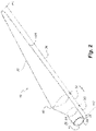
- Fig. 2 shows a schematic view of an exemplary wind turbine blade 10.
- the wind turbine blade 10 has the shape of a conventional wind turbine blade with a root end and a tip end and comprises a root region 30 closest to the hub, a profiled or an airfoil region 34 furthest away from the hub and a transition region 32 between the root region 30 and the airfoil region 34.
- the blade 10 comprises a leading edge 18 facing the direction of rotation of the blade 10, when the blade is mounted on the hub, and a trailing edge 20 facing the opposite direction of the leading edge 18.
- the airfoil region 34 (also called the profiled region) has an ideal or almost ideal blade shape with respect to generating lift, whereas the root region 30 due to structural considerations has a substantially circular or elliptical cross-section, which for instance makes it easier and safer to mount the blade 10 to the hub.
- the diameter (or the chord) of the root region 30 may be constant along the entire root area 30.
- the transition region 32 has a transitional profile gradually changing from the circular or elliptical shape of the root region 30 to the airfoil profile of the airfoil region 34.
- the chord length of the transition region 32 typically increases with increasing distance r from the hub.
- the airfoil region 34 has an airfoil profile with a chord extending between the leading edge 18 and the trailing edge 20 of the blade 10. The width of the chord decreases with increasing distance r from the hub.
- a shoulder 40 of the blade 10 is defined as the position, where the blade 10 has its largest chord length.
- the shoulder 40 is typically provided at the boundary between the transition region 32 and the airfoil region 34.
- chords of different sections of the blade normally do not lie in a common plane, since the blade may be twisted and/or curved (i.e. pre-bent), thus providing the chord plane with a correspondingly twisted and/or curved course, this being most often the case in order to compensate for the local velocity of the blade being dependent on the radius from the hub.
- the wind turbine blade 10 comprises a shell comprising two blade shell parts made of fibre-reinforced polymer and is typically made as a pressure side or upwind blade shell part 24 and a suction side or downwind blade shell part 26 that are glued together along bond lines 28 extending along the trailing edge 20 and the leading edge 18 of the blade 10.
- the root ends of the blade shell parts 24, 26 has a semi-circular or semi-oval outer cross-sectional shape.
- Figs. 3 and 4 depict parameters, which may be used to explain the geometry of blade shell parts to be manufactured according to the invention.
- Fig. 3 shows a schematic view of an airfoil profile 50 of a typical blade of a wind turbine depicted with the various parameters, which are typically used to define the geometrical shape of an airfoil.
- the airfoil profile 50 has a pressure side 52 and a suction side 54, which during use - i.e. during rotation of the rotor - normally face towards the windward (or upwind) side and the leeward (or downwind) side, respectively.
- the airfoil 50 has a chord 60 with a chord length c extending between a leading edge 56 and a trailing edge 58 of the blade.
- the airfoil 50 has a thickness t, which is defined as the distance between the pressure side 52 and the suction side 54.
- the thickness t of the airfoil varies along the chord 60.
- the deviation from a symmetrical profile is given by a camber line 62, which is a median line through the airfoil profile 50.
- the median line can be found by drawing inscribed circles from the leading edge 56 to the trailing edge 58.
- the median line follows the centres of these inscribed circles and the deviation or distance from the chord 60 is called the camber f.
- the asymmetry can also be defined by use of parameters called the upper camber (or suction side camber) and lower camber (or pressure side camber), which are defined as the distances from the chord 60 and the suction side 54 and pressure side 52, respectively.
- Airfoil profiles are often characterised by the following parameters: the chord length c, the maximum camber f, the position d f of the maximum camber f, the maximum airfoil thickness t, which is the largest diameter of the inscribed circles along the median camber line 62, the position d t of the maximum thickness t, and a nose radius (not shown). These parameters are typically defined as ratios to the chord length c. Thus, a local relative blade thickness t / c is given as the ratio between the local maximum thickness t and the local chord length c. Further, the position d p of the maximum pressure side camber may be used as a design parameter, and of course also the position of the maximum suction side camber.
- Fig. 4 shows other geometric parameters of the blade and blade shell parts.
- the blade and blade shell parts have a total blade length L.
- the diameter of the root is defined as X.
- the blade/blade shell parts is/are provided with a prebend, which is defined as ⁇ y, which corresponds to the out of plane deflection from a pitch axis 22 of the blade.
- Wind turbine blades have over the time become longer and longer and may now exceed a length of 70 metres. Further, the root diameter of blades has increased. The length of the blade, the root diameter as well as the shape of the blades with respect to shoulder, twist and prebending makes it increasingly difficult to provide wind turbine blades with sufficient and desired mechanical strength and dynamic properties.
- Fig. 5 is an exemplary first cross-section perpendicular to the longitudinal axis X of a wind turbine blade according to the present invention at a first distance from the root end of the wind turbine blade.
- the wind turbine blade 10 comprises a profiled contour with a leading edge 18 and a trailing edge 20 and a chord 60 extending between the leading edge 18 and the trailing edge 20, a blade shell 64 with a pressure side 52 and a suction side 54, a first main spar cap 70 integrated in the pressure side of the blade shell 64, and a second main spar cap 72 integrated in the suction side of the blade shell 64.
- the wind turbine blade 10 comprises one or more shear webs including a first shear web 74 and optionally a second shear web 76, the shear web(s) being connected between the first main spar cap 70 and the second main spar cap 72.
- the blade shell 64 comprises a first load carrying structure 78 arranged at the leading edge 18, wherein the first load carrying structure has a first extension including a first primary extension E 1,1 on a first side (pressure side 52) of the chord 60.
- the first primary extension is at least 60 % of the first extension (E 1,1 + E 1,2 ).
- the first load carrying structure comprises 20 layers of reinforcement material.
- the blade shell 64 optionally comprises a second load carrying structure 90 arranged at the trailing edge 20, wherein the second load carrying structure has a second extension including a second primary extension E 2,1 on a second side (suction side 54) of the chord 60.
- the second primary extension is at least 60 % of the second extension (E 2,1 + E 2,2 ).
- the second load carrying structure 90 comprises 20 layers of reinforcement material.
- the first load carrying structure and optionally the second load carrying structure is/are designed to tailor the dynamic properties of the wind turbine blade, e.g. in order to improve the edgewise damping of the wind turbine blade.
- Blade parameters for exemplary wind turbine blades B1, ... B6 in a first cross section at a first distance and/or a second cross section at a second distance from the root end are set out in Table 1, wherein E 1,1 is the first primary extension and E 1 is the first extension of a first load carrying structure. E 2,1 is the second primary extension and E 2 is the second extension of a second load carrying structure. N1 is the number of reinforcement material layers for the first load carrying structure on a first side of the chord or on a first side of a glue joint of the wind turbine blade or on a first blade shell part of the wind turbine blade.
- N2 is the number of reinforcement material layers for the first load carrying structure on a second side of the chord or on a second side of a glue joint of the wind turbine blade or on a second blade shell part of the wind turbine blade.
- M1 is the number of reinforcement material layers for the second load carrying structure on a second side of the chord or on a second side of a glue joint of the wind turbine blade or on a second blade shell part of the wind turbine blade.
- M2 is the number of reinforcement material layers for the second load carrying structure on a first side of the chord or on a first side of a glue joint of the wind turbine blade or on a first blade shell part of the wind turbine blade.
- blade parameter values for a wind turbine blade such as B1
- blade parameter values for another wind turbine blade such as B5
- B5 may be indicative for a second cross section of the exemplary wind turbine blade.
- Table 1 Blade parameters for exemplary wind turbine blades in first cross-sections.
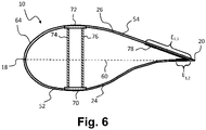
- Fig. 6 is an exemplary first cross-section perpendicular to the longitudinal axis X of a wind turbine blade according to the present invention at a first distance from the root end of the wind turbine blade.
- the wind turbine blade 10 comprises a profiled contour with a leading edge 18 and a trailing edge 20 and a chord 60 extending between the leading edge 18 and the trailing edge 20, a blade shell 64 with a pressure side 52 and a suction side 54, a first main spar cap 70 integrated in the pressure side of the blade shell 64, and a second main spar cap 72 integrated in the suction side of the blade shell 64.
- the wind turbine blade 10 comprises one or more shear webs including a first shear web 74 and optionally a second shear web 76, the shear web(s) being connected between the first main spar cap 70 and the second main spar cap 72.
- the blade shell 64 comprises a first load carrying structure 78 arranged at the trailing edge 20, wherein the first load carrying structure has a first extension including a first primary extension E 1,1 on a first side (suction side 54) of the chord 60.
- the first primary extension is at least 60 % of the first extension (E 1,1 + E 1,2 ).
- the first load carrying structure comprises 20 layers of reinforcement material.
- the first load carrying structure and optionally the second load carrying structure is/are designed to tailor the dynamic properties, e.g. edgewise damping, of the wind turbine blade, e.g. in order to improve or obtain a desired edgewise damping of the wind turbine blade.
Description
- The present disclosure pertains to the field of wind turbine blades. In particular, the present disclosure relates to a wind turbine blade with desired dynamic properties and a method of manufacturing a wind turbine blade.
- Wind turbine blades of fibre-reinforced polymer and in particular the aerodynamic shells of wind turbine blades are usually manufactured in moulds, where the pressure side and the suction side of the blade are manufactured separately by arranging glass fibre mats and/or other fibre-reinforcement material, such as carbon fibre, in each of the two mould parts. Then, the two halves are glued together, often by means of internal flange parts. Glue is applied to the inner face of the lower blade half before the upper blade half is lowered thereon. Additionally, one or two reinforcing profiles (beams) are often attached to the inside of the lower blade half prior to gluing to the upper blade half.
- The aerodynamic shell parts are typically made by use of Vacuum Assisted Resin Transfer Moulding (VARTM), where a plurality of fibre mats are arranged on top of a rigid mould parts and possibly also a core material to provide parts having a sandwich structure. When the fibre mats have been stacked and overlapped so as to form the final shape of the wind turbine blade shell part, a flexible vacuum bag is arranged on top of the fibre mats and sealed against the rigid mould part, thereby forming a mould cavity containing the fibre mats. Resin inlets and vacuum outlets are connected to the mould cavity. First the mould cavity is evacuated via the vacuum outlets so as to form an under-pressure in the mould cavity, after which a supply of liquid resin is supplied via the resin inlets. The resin is forced into the mould cavity due to the pressure differential and impregnates the fibre material of the fibre mats. When the fibre material has been fully impregnated, the resin is cured in order to form the final composite structure, i.e. the blade shell part.
- Wind turbine blades have become increasingly longer of the years and blades having a length of more than 70 metres are now commercially available on the market. This also means that the requirements to the mechanical strength of the wind turbine blade has increased dramatically. Due to the large size, it has become increasingly complicated to manufacture wind turbine blades with desired mechanical strength and in particular to provide a wind turbine blade with satisfactory dynamic properties.
-
US 2015/0151390 discloses wind turbine rotor blade components and an apparatus for storing, tapering, cutting and dispensing preform layers of material includes a device for storing coiled lengths of the preform layers of material and a mechanism for receiving coiled lengths of the preform layers of material. - Thus, there is a need for a wind turbine blade with improved dynamic properties.
- Accordingly, there is provided a wind turbine blade according to claim 1 comprising a profiled contour with a leading edge and a trailing edge and a chord extending between the leading edge and the trailing edge, a blade shell with a pressure side and a suction side, a first main spar cap integrated in the pressure side of the blade shell, a second main spar cap integrated in the suction side of the blade shell, and one or more shear webs connected between the pressure side and the suction side, e.g. between the first main spar cap and the second main spar cap. The blade shell comprises at least a first load carrying structure arranged at the leading edge or the trailing edge of the wind turbine blade. The first load carrying structure optionally has a first extension including a first primary extension on a first side of the chord or on a first side of a glue joint of the wind turbine blade or on a first blade shell part of the wind turbine blade. The first primary extension is at least 70 % of the first extension.
- Also provided is a method of manufacturing a wind turbine blade according to claim 13 J Z comprising a profiled contour with a leading edge and a trailing edge and a chord extending between the leading edge and the trailing edge, a blade shell with a pressure side and a suction side, a first main spar cap integrated in the pressure side of the blade shell, a second main spar cap integrated in the suction side of the blade shell, and one or more shear webs connected between the first main spar cap and the second main spar cap. The method comprises arranging a first reinforcement fibre layup at the leading edge or the trailing edge, wherein the first reinforcement fibre layup has a first extension including a first primary extension on a first side of the chord or on a first blade shell part, wherein the first primary extension is at least 70 % of the first extension.
- A wind turbine blade extends from a root end to a tip end along a longitudinal axis and comprises a root region, a transition region, and an airfoil region. The transition region of the wind turbine blade comprises a shoulder defining a maximum chord of the wind turbine blade.
- The present disclosure advantageously relates to wind turbine blades and manufacture of wind turbine blades, e.g. having a blade length of at least 40 metres, or at least 45 metres, or even at least 50 metres. The wind turbine blade may be prebent so that, when mounted on an upwind configured horizontal wind turbine in a non-loaded state, they will curve forward out of the rotor plane so that the tip to tower clearance is increased. A wind turbine blade has a leading edge and a trailing edge with an inner surface and an outer surface. The inner surface of a wind turbine blade is a surface that is not exposed to the surroundings. The outer surface of a wind turbine blade is a surface that is exposed to the surroundings.
- The wind turbine blade comprises a profiled contour with a leading edge and a trailing edge and a chord extending between the leading edge and the trailing edge. Touching points of the chord on the leading edge form a leading edge chord line and touching point of the chord on the trailing edge form a trailing edge chord line.
- The wind turbine blade comprises a first main spar cap integrated in the pressure side of the blade shell and a second main spar cap integrated in the suction side of the blade shell. One or more shear webs, such as a first shear web and/or a second shear web, are connected between the first main spar cap and the second main spar cap. The wind turbine blade may comprise a first secondary spar cap integrated in the pressure side of the blade shell. The wind turbine blade may comprise a second secondary spar cap integrated in the suction side of the blade shell,
- The blade shell comprises one or more load carrying structures, such as the first load carrying structure and/or a second load carrying structure. A load carrying structure, such as the first load carrying structure and/or a second load carrying structure, comprises reinforcement material, e.g. one or more layers of reinforcement material.
- A layer of reinforcement material may have a first elastic modulus E1 in a first direction and a second elastic modulus E2 in a second direction perpendicular to the first direction. In one or more exemplary wind turbine blades, E1/E2 > 2.0, e.g. E1/E2 > 2.3 or E1/E2 > 2.6. In one or more advantageous wind turbine blades, E1/E2 > 3.0. The reinforcement material may comprise any type of reinforcement fibres suitable for reinforcing large composite structures, such as glass fibres, carbon fibres and/or aramid fibres. The reinforcement material or layer(s) of reinforcement material may comprise unidirectional fibres, biaxial fibres, triaxial fibres or randomly oriented fibres. In one or more advantageous wind turbine blades, a load carrying structure, such as the first load carrying structure and/or a second load carrying structure, comprises one or more unidirectional fibre layers. Unidirectional fibres or a unidirectional fibre layer may have at least 75% of the fibres (weight or volume) in one direction (± 15 degrees), such as at least 90% of the fibres in one direction (± 15 degrees).
- A load carrying structure, such as the first load carrying structure and/or the second load carrying structure, may have a length of at least 5 m, such as at least 7 m. In one or more exemplary wind turbine blades, the first load carrying structure and/or the second load carrying structure has a length of at least 10 m. A load carrying structure, such as the first load carrying structure and/or the second load carrying structure, may have a length of at least 0.1 * L, wherein L is the length of the wind turbine blade. In one or more exemplary wind turbine blades, the first load carrying structure and/or the second load carrying structure, may have a length of at least 0.15 * L or at least 0.2 *L, wherein L is the length of the wind turbine blade. In one or more exemplary wind turbine blades, the first load carrying structure and/or the second load carrying structure, may have a length of at least 0.3 * L or at least 0.5 *L, wherein L is the length of the wind turbine blade.
- The first load carrying structure and/or the second load carrying structure enables the blade designer to modify and tailor the dynamic behavior of the wind turbine blade.
- The blade shell comprises at least a first load carrying structure arranged at the leading edge or the trailing edge.
- A load carrying structure may be arranged at the leading edge when the load carrying structure at least partly extends within a distance less than 0.2 * c from the leading edge along the chord, where c is the chord length. In one or more exemplary wind turbine blades, a load carrying structure is arranged at the leading edge when the load carrying structure at least partly extends within a distance less than 0.1 * c from the leading edge along the chord, where c is the chord length.
- A load carrying structure may be arranged at the trailing edge when the load carrying structure at least partly extends within a distance less than 0.3 * c from the trailing edge along the chord, where c is the chord length. In one or more exemplary wind turbine blades, a load carrying structure is arranged at the trailing edge when the load carrying structure extends within a distance less than 0.1 * c from the trailing edge along the chord, where c is the chord length.
- The first load carrying structure may be asymmetric about the leading edge chord line or the trailing edge chord line. In one or more exemplary wind turbine blades, the first load carrying structure is asymmetric at the leading edge with regard to the chord or with regard to a glue joint.
- Different numbers and/or distribution of reinforcement material layers on different sides of the chord or on different sides of a glue joint or on different blade shell parts may employ an asymmetric load carrying structure. Additionally, or alternatively, reinforcement material layers with varying size (extension) may provide an asymmetric load carrying structure.
- The first load carrying structure, e.g. in one or more cross-sections, such as a first cross-section and/or a second cross-section, perpendicular to the longitudinal axis, has a first extension including a first primary extension on a first side of the chord or on a first side of a glue joint, such as a leading edge glue joint at the leading edge or a trailing edge glue joint at the trailing edge. The first side may be the pressure side of the wind turbine blade.
- The first cross-section may be at a first distance from a root end of the wind turbine blade. The second cross-section may be at a second distance from the root end of the wind turbine blade. The first distance may be in the range from 0 to 20 m, such as 10 m. The first distance may be in the range from 0 to 0.25*L, where L is the blade length.
- The second distance may be in the range from 20 m to 40 m, such as 30 m. The second distance may be larger than 0.2*L, such as in the range from 0.25*L to 0.8*L, where L is the blade length. The difference between the first distance and the second distance may be at least 2 m, such as at least 5 m.
- A load carrying structure, such as the first load carrying structure and/or the second load carrying structure, may have different extensions in different cross-sections, e.g. in the first cross-section and the second cross-section. For example, the extension of a load carrying structure, such as the first load carrying structure and/or the second load carrying structure, may decrease, e.g. stepwise, from a first cross-section to a second cross-section, e.g. where the first cross-section is closer to that root end than the second cross-section.
- The first primary extension may be at least 60 % of the first extension, such as at least 70% of the first extension. In one or more exemplary wind turbine blades, the first primary extension is about 80 % of the first extension or at least 80 % of the first extension. The first primary extension may constitute the first extension, i.e. be 100 % of the first extension.
- The first primary extension may be in the range from 10 cm to about 200 cm, such as in the range from 50 cm to 150 cm, such as about 80 cm. In an exemplary wind turbine blade, the first primary extension is at least 50 cm, such as at least 200 cm.
- The first extension of the first load carrying structure may include a first secondary extension on a second side of the chord on a second side of a glue joint, such as the leading edge glue joint or the trailing edge glue joint if present. The first secondary extension may be less than 40 % of the first extension, such as less than 30 % of the first extension. In one or more exemplary wind turbine blades, the first secondary extension is about 20 % of the first extension or less than 20 % of the first extension. In one or more exemplary wind turbine blades, the first secondary extension is larger than 5 % of the first extension.
- The first secondary extension may be in the range from 10 cm to 100 cm, such as in the range from 15 cm to 50 cm. In one or more exemplary wind turbine blades, the first secondary extension is about 20 cm.
- In one or more exemplary wind turbine blades, the first load carrying structure is arranged at the leading edge, the first side is the pressure side, and the first primary extension is optionally at least 80 % of the first extension.
- In one or more exemplary wind turbine blades, the first load carrying structure is arranged at the trailing edge, the first side is the suction side, and the first primary extension is optionally at least 80 % of the first extension.
- The first load carrying structure may, e.g. in one or more cross-sections, such as a first cross-section and/or a second cross-section, perpendicular to the longitudinal axis, comprise at least 5 layers of reinforcement material, preferably at least 10 layers of reinforcement material.
- In one or more exemplary wind turbine blades, the first load carrying structure may, e.g. in the first cross-section and/or in the second cross-section, comprise at least 20 layers of reinforcement material.
- The first load carrying structure may comprise N1 layers of reinforcement material on a first side of the chord or on a first side of a glue joint of the wind turbine blade or on a first blade shell part of the wind turbine blade. N1 may be in the range from 5 to 50, such as at least 10.
- The first load carrying structure may comprise N2 layers of reinforcement material on a second side of the chord or on a second side of a glue joint of the wind turbine blade or on a second blade shell part of the wind turbine blade. N2 may be in the range from 1 to 50, such as at least 10. N2 may be less than N1.
- The blade shell may comprise a second load carrying structure arranged at the leading edge or the trailing edge.
- The second load carrying structure may be asymmetric about the leading edge chord line or the trailing edge chord line. In one or more exemplary wind turbine blades, the second load carrying structure is asymmetric at the trailing edge with regard to the chord or with regard to a glue joint.
- The second load carrying structure may, e.g. in the first cross-section and/or the second cross-section, have a second extension including a second primary extension on a second side of the chord or on a second side of a glue joint, such as a leading edge glue joint at the leading edge or a trailing edge glue joint at the trailing edge. The second side may be the suction side of the wind turbine blade.
- The second primary extension may be at least 60 % of the second extension, such as at least 70% of the second extension. In one or more exemplary wind turbine blades, the second primary extension is about 75 % of the second extension or at least 75 % of the second extension. The second primary extension may constitute the second extension, i.e. be 100 % of the second extension.
- The second primary extension may be in the range from 10 cm to about 150 cm, such as in the range from 80 cm to 130 cm. In an exemplary wind turbine blade, the second primary extension is at least 50 cm, such as about 120 cm.
- The second extension of the second load carrying structure may include a second secondary extension on a first side of the chord and/or on a first side of a glue joint, such as the leading edge glue joint or the trailing edge glue joint if present. The second secondary extension may be less than 40 % of the second extension, such as less than 30 % of the second extension. In one or more exemplary wind turbine blades, the second secondary extension is about 25 % of the second extension or less than 25 % of the second extension. In one or more exemplary wind turbine blades, the second secondary extension is larger than 5 % of the second extension.
- The second secondary extension may be in the range from 10 cm to about 100 cm, such as in the range from 20 cm to 60 cm. In an exemplary wind turbine blade, the second secondary extension is about 40 cm.
- In one or more exemplary wind turbine blades, the second load carrying structure is arranged at the trailing edge, the second side is the suction side, and the second primary extension is optionally at least 80 % of the first extension.
- The second load carrying structure may, e.g. in the first cross-section and/or the second cross-section, comprise at least 5 layers of reinforcement material, preferably at least 10 layers of reinforcement material.
- In one or more exemplary wind turbine blades, the second load carrying structure may, e.g. in the first cross-section and/or in the second cross-section, comprise at least 20 layers of reinforcement material.
- The second load carrying structure may comprise M1 layers of reinforcement material on a second side of the chord or on a second side of a glue joint of the wind turbine blade or on a second blade shell part of the wind turbine blade. M1 may be in the range from 5 to 50, such as at least 10.
- The second load carrying structure may comprise M2 layers of reinforcement material on a first side of the chord or on a first side of a glue joint of the wind turbine blade or on a first blade shell part of the wind turbine blade. M2 may be in the range from 1 to 50, such as at least 10. M2 may be less than M1.
- An extension may be measured perpendicular to the longitudinal direction of the wind turbine blade. An extension may be measured as the mean extension of different layers of a load carrying structure or a weighted sum of the extension of different layers.
- The first load carrying structure and/or the second load carrying structure may be integrated in the blade shell.
- The wind turbine blade may comprise a first blade shell part and a second blade shell part. The first blade shell part and the second blade shell part may be joined along one or more glue joints, such as a leading edge joint and a trailing edge glue joint. The first load carrying structure may be arranged in the first blade shell part. In one or more exemplary wind turbine blades, the first primary extension is in the first blade shell part and the first secondary extension is in the second blade shell part. In one or more exemplary wind turbine blades, the first extension is in the first blade shell part The second load carrying structure may be arranged in the second blade shell part. In one or more exemplary wind turbine blades, the second primary extension is in the second blade shell part and the second secondary extension is in the first blade shell part. In one or more exemplary wind turbine blades, the second extension is in the second blade shell part.
- The disclosed method comprises arranging a first reinforcement fibre layup at the leading edge or the trailing edge. Arranging a first reinforcement fibre layup may comprise or consist of arranging a first primary reinforcement fibre layup at the leading edge of a first blade shell part. A reinforcement fibre layup may comprise a plurality of reinforcement material layers such as at least 10 layers, e.g. in a first cross-section and/or in a second cross-section.
- Arranging a first reinforcement fibre layup may comprise or consist of arranging a first primary reinforcement fibre layup at the trailing edge of a second blade shell part of the wind turbine blade.
- The method may comprise arranging a first reinforcement fibre layup at the leading edge or the trailing edge. Arranging a first reinforcement fibre layup may comprise or consist of arranging a first primary reinforcement fibre layup at the leading edge of a first blade shell part. Arranging a first reinforcement fibre layup may comprise arranging a first secondary reinforcement fibre layup at the leading edge of a second blade shell part.
- The first primary extension, i.e. the extension of first primary reinforcement fibre layup, may be on a first blade shell part of the wind turbine. The first extension may comprise a first secondary extension on a second blade shell part of the wind turbine blade.
- The method may comprise arranging a second reinforcement fibre layup at the trailing edge, wherein the second reinforcement fibre layup has a second extension including a second primary extension on a second side of the chord, wherein the second primary extension is at least 60 % of the second extension.
- The method optionally comprises supplying resin to the first and/or second reinforcement fibre layup and curing the resin to form a first blade shell part and/or a second blade shell part.
- The method may comprise joining first and second blade shell parts of the wind turbine blade. The method may be a method of manufacturing a wind turbine blade as described herein.
- The invention is explained in detail below with reference to the drawings, in which
-
Fig. 1 shows a wind turbine, -
Fig. 2 shows a schematic view of a wind turbine blade, -
Fig. 3 shows a schematic view of an airfoil profile, -
Fig. 4 shows a schematic view of a wind turbine blade, seen from above and from the side, -
Fig. 5 shows a cross-sectional view of a wind turbine blade according to the invention, and -
Fig. 6 shows a cross-sectional view of a wind turbine blade according to the invention. - The present invention relates to manufacture of blade shell parts of wind turbine blades for horizontal axis wind turbines (HAWTs).
-
Fig. 1 illustrates a conventional modern upwind wind turbine according to the so-called "Danish concept" with a tower 4, a nacelle 6 and a rotor with a substantially horizontal rotor shaft. The rotor includes ahub 8 and threewind turbine blades 10 extending radially from thehub 8, each having ablade root 16 nearest the hub and ablade tip 14 furthest from thehub 8. The rotor has a radius denoted R. -
Fig. 2 shows a schematic view of an exemplarywind turbine blade 10. Thewind turbine blade 10 has the shape of a conventional wind turbine blade with a root end and a tip end and comprises aroot region 30 closest to the hub, a profiled or anairfoil region 34 furthest away from the hub and atransition region 32 between theroot region 30 and theairfoil region 34. Theblade 10 comprises aleading edge 18 facing the direction of rotation of theblade 10, when the blade is mounted on the hub, and a trailingedge 20 facing the opposite direction of the leadingedge 18. - The airfoil region 34 (also called the profiled region) has an ideal or almost ideal blade shape with respect to generating lift, whereas the
root region 30 due to structural considerations has a substantially circular or elliptical cross-section, which for instance makes it easier and safer to mount theblade 10 to the hub. The diameter (or the chord) of theroot region 30 may be constant along theentire root area 30. Thetransition region 32 has a transitional profile gradually changing from the circular or elliptical shape of theroot region 30 to the airfoil profile of theairfoil region 34. The chord length of thetransition region 32 typically increases with increasing distance r from the hub. Theairfoil region 34 has an airfoil profile with a chord extending between theleading edge 18 and the trailingedge 20 of theblade 10. The width of the chord decreases with increasing distance r from the hub. - A
shoulder 40 of theblade 10 is defined as the position, where theblade 10 has its largest chord length. Theshoulder 40 is typically provided at the boundary between thetransition region 32 and theairfoil region 34. - It should be noted that the chords of different sections of the blade normally do not lie in a common plane, since the blade may be twisted and/or curved (i.e. pre-bent), thus providing the chord plane with a correspondingly twisted and/or curved course, this being most often the case in order to compensate for the local velocity of the blade being dependent on the radius from the hub.
- The
wind turbine blade 10 comprises a shell comprising two blade shell parts made of fibre-reinforced polymer and is typically made as a pressure side or upwindblade shell part 24 and a suction side or downwindblade shell part 26 that are glued together alongbond lines 28 extending along the trailingedge 20 and the leadingedge 18 of theblade 10. Typically, the root ends of theblade shell parts -
Figs. 3 and 4 depict parameters, which may be used to explain the geometry of blade shell parts to be manufactured according to the invention. -
Fig. 3 shows a schematic view of anairfoil profile 50 of a typical blade of a wind turbine depicted with the various parameters, which are typically used to define the geometrical shape of an airfoil. Theairfoil profile 50 has apressure side 52 and asuction side 54, which during use - i.e. during rotation of the rotor - normally face towards the windward (or upwind) side and the leeward (or downwind) side, respectively. Theairfoil 50 has achord 60 with a chord length c extending between a leading edge 56 and a trailingedge 58 of the blade. Theairfoil 50 has a thickness t, which is defined as the distance between thepressure side 52 and thesuction side 54. The thickness t of the airfoil varies along thechord 60. The deviation from a symmetrical profile is given by acamber line 62, which is a median line through theairfoil profile 50. The median line can be found by drawing inscribed circles from the leading edge 56 to the trailingedge 58. The median line follows the centres of these inscribed circles and the deviation or distance from thechord 60 is called the camber f. The asymmetry can also be defined by use of parameters called the upper camber (or suction side camber) and lower camber (or pressure side camber), which are defined as the distances from thechord 60 and thesuction side 54 andpressure side 52, respectively. - Airfoil profiles are often characterised by the following parameters: the chord length c, the maximum camber f, the position df of the maximum camber f, the maximum airfoil thickness t, which is the largest diameter of the inscribed circles along the
median camber line 62, the position dt of the maximum thickness t, and a nose radius (not shown). These parameters are typically defined as ratios to the chord length c. Thus, a local relative blade thickness t/c is given as the ratio between the local maximum thickness t and the local chord length c. Further, the position dp of the maximum pressure side camber may be used as a design parameter, and of course also the position of the maximum suction side camber. -
Fig. 4 shows other geometric parameters of the blade and blade shell parts. The blade and blade shell parts have a total blade length L. As shown inFig. 3 , the root end is located at position r = 0, and the tip end located at r = L. Theshoulder 40 of the blade shell parts is located at a position r = Lw, and has a shoulder width W, which equals the chord length at theshoulder 40. The diameter of the root is defined as X. Further, the blade/blade shell parts is/are provided with a prebend, which is defined as Δy, which corresponds to the out of plane deflection from apitch axis 22 of the blade. - Wind turbine blades have over the time become longer and longer and may now exceed a length of 70 metres. Further, the root diameter of blades has increased. The length of the blade, the root diameter as well as the shape of the blades with respect to shoulder, twist and prebending makes it increasingly difficult to provide wind turbine blades with sufficient and desired mechanical strength and dynamic properties.
-
Fig. 5 is an exemplary first cross-section perpendicular to the longitudinal axis X of a wind turbine blade according to the present invention at a first distance from the root end of the wind turbine blade. Thewind turbine blade 10 comprises a profiled contour with aleading edge 18 and a trailingedge 20 and achord 60 extending between theleading edge 18 and the trailingedge 20, ablade shell 64 with apressure side 52 and asuction side 54, a firstmain spar cap 70 integrated in the pressure side of theblade shell 64, and a secondmain spar cap 72 integrated in the suction side of theblade shell 64. Further, thewind turbine blade 10 comprises one or more shear webs including afirst shear web 74 and optionally asecond shear web 76, the shear web(s) being connected between the firstmain spar cap 70 and the secondmain spar cap 72. - The
blade shell 64 comprises a firstload carrying structure 78 arranged at theleading edge 18, wherein the first load carrying structure has a first extension including a first primary extension E1,1 on a first side (pressure side 52) of thechord 60. The first primary extension is at least 60 % of the first extension (E1,1 + E1,2). The first load carrying structure comprises 20 layers of reinforcement material. - Further, the
blade shell 64 optionally comprises a secondload carrying structure 90 arranged at the trailingedge 20, wherein the second load carrying structure has a second extension including a second primary extension E2,1 on a second side (suction side 54) of thechord 60. The second primary extension is at least 60 % of the second extension (E2,1 + E2,2). The secondload carrying structure 90 comprises 20 layers of reinforcement material. - The first load carrying structure and optionally the second load carrying structure is/are designed to tailor the dynamic properties of the wind turbine blade, e.g. in order to improve the edgewise damping of the wind turbine blade.
- Blade parameters for exemplary wind turbine blades B1, ... B6 in a first cross section at a first distance and/or a second cross section at a second distance from the root end are set out in Table 1, wherein E1,1 is the first primary extension and E1 is the first extension of a first load carrying structure. E2,1 is the second primary extension and E2 is the second extension of a second load carrying structure. N1 is the number of reinforcement material layers for the first load carrying structure on a first side of the chord or on a first side of a glue joint of the wind turbine blade or on a first blade shell part of the wind turbine blade. N2 is the number of reinforcement material layers for the first load carrying structure on a second side of the chord or on a second side of a glue joint of the wind turbine blade or on a second blade shell part of the wind turbine blade. M1 is the number of reinforcement material layers for the second load carrying structure on a second side of the chord or on a second side of a glue joint of the wind turbine blade or on a second blade shell part of the wind turbine blade. M2 is the number of reinforcement material layers for the second load carrying structure on a first side of the chord or on a first side of a glue joint of the wind turbine blade or on a first blade shell part of the wind turbine blade. The different blade parameter values for different exemplary wind turbine blades may be taken alone, i.e. define a common parameter for a set of wind turbine blades according to the invention, or combined, e.g. E1,1/E1 for B1 may be combined with N1 of B4 as another exemplary wind turbine blade according to the invention. Further, blade parameter values for a wind turbine blade, such as B1, may be indicative for a first cross section of an exemplary wind turbine blade, and blade parameter values for another wind turbine blade, such as B5, may be indicative for a second cross section of the exemplary wind turbine blade.
Table 1: Blade parameters for exemplary wind turbine blades in first cross-sections. B1 B2 B3 B4 B5 B6 E1,1/E1 >60% 45%-70% >70% >70% >80% 80% E2,1/E2 >60% >70% >70% 75% N1 >10 > N2 10 <N2 >20 N2 >5 < N1 10 >N1 >10 M1 >10 >20 M2 >5 >10 -
Fig. 6 is an exemplary first cross-section perpendicular to the longitudinal axis X of a wind turbine blade according to the present invention at a first distance from the root end of the wind turbine blade. Thewind turbine blade 10 comprises a profiled contour with aleading edge 18 and a trailingedge 20 and achord 60 extending between theleading edge 18 and the trailingedge 20, ablade shell 64 with apressure side 52 and asuction side 54, a firstmain spar cap 70 integrated in the pressure side of theblade shell 64, and a secondmain spar cap 72 integrated in the suction side of theblade shell 64. Further, thewind turbine blade 10 comprises one or more shear webs including afirst shear web 74 and optionally asecond shear web 76, the shear web(s) being connected between the firstmain spar cap 70 and the secondmain spar cap 72. - The
blade shell 64 comprises a firstload carrying structure 78 arranged at the trailingedge 20, wherein the first load carrying structure has a first extension including a first primary extension E1,1 on a first side (suction side 54) of thechord 60. The first primary extension is at least 60 % of the first extension (E1,1 + E1,2). The first load carrying structure comprises 20 layers of reinforcement material. - The first load carrying structure and optionally the second load carrying structure is/are designed to tailor the dynamic properties, e.g. edgewise damping, of the wind turbine blade, e.g. in order to improve or obtain a desired edgewise damping of the wind turbine blade.
- The invention has been described with reference to preferred embodiments. However, the scope of the invention is not limited to the illustrated embodiments, and alterations and modifications can be carried out without deviating from the scope of the invention that is defined by the following claims. The invention is not limited to the embodiments described herein, and may be modified or adapted without departing from the scope of the present invention.
-
- 2
- wind turbine
- 4
- tower
- 6
- nacelle
- 8
- hub
- 10
- wind turbine blade
- 14
- blade tip
- 15
- tip end section
- 16
- blade root
- 17
- root end face
- 18
- leading edge
- 20
- trailing edge
- 22
- pitch axis
- 24
- pressure side blade shell part / first or upwind blade shell part
- 26
- suction side blade shell part / second or downwind blade shell part
- 28
- bond lines
- 29
- horizontal
- 30
- root region
- 32
- transition region
- 34
- airfoil region
- 50
- airfoil profile
- 52
- pressure side / upwind side
- 54
- suction side / downwind side
- 56
- leading edge
- 58
- trailing edge
- 60
- chord
- 62
- camber line / median line
- 64
- blade shell
- 70
- first main spar cap
- 72
- second main spar cap
- 74
- first shear web
- 76
- second shear web
- 78
- first load carrying structure
- 90
- second load carrying structure
- c
- chord length
- dt
- position of maximum thickness
- df
- position of maximum camber
- dp
- position of maximum pressure side camber
- f
- camber
- lf
- longitudinal distance between root end frames
- lo
- longitudinal extent of blade tip overhang
- L
- blade length
- r
- local radius, radial distance from blade root
- t
- thickness
- D
- blade root diameter
- Δy
- prebend
- X
- longitudinal axis
- E1,1
- first primary extension of first load carrying structure
- E1,2
- first secondary extension of first load carrying structure
- E2,1
- second primary extension of second load carrying structure
- E2,2
- second secondary extension of second load carrying structure
Claims (16)
- A wind turbine blade (10) comprising- a profiled contour with a leading edge (56) and a trailing edge (58) and a chord (60) extending between the leading edge and the trailing edge,- a blade shell (64) with a pressure side and a suction side,- a first main spar cap (70) integrated in the pressure side of the blade shell,- a second main spar cap (72) integrated in the suction side of the blade shell, and- one or more shear webs (74, 76) connected between the first main spar cap and the second main spar cap,wherein the blade shell comprises at least a first load carrying structure (78) comprising one or more unidirectional fibre layers and being arranged at the leading edge, wherein the first load carrying structure has a first extension including a first primary extension (E1,1) on a first side of the chord, characterized in that the first primary extension is at least 70 % of the first extension.
- Wind turbine blade according to claim 1, wherein the first load carrying structure is designed to tailor the edgewise damping of the wind turbine blade.
- Wind turbine blade according to any of claims 1-2, wherein the first extension of the first load carrying structure includes a first secondary extension (E1,2) on a second side of the chord, wherein the first secondary extension is less than 20 % of the first extension.
- Wind turbine blade according to any of the preceding claims, wherein the first load carrying structure is arranged at the leading edge, wherein the first side of the chord is the pressure side, and wherein the first primary extension is at least 80 % of the first extension.
- Wind turbine blade according to any of the preceding claims, wherein the first load carrying structure comprises at least 10 layers of reinforcement material.
- Wind turbine blade according to any of the preceding claims, wherein the blade shell comprises a second load carrying structure (90) arranged at the trailing edge, wherein the second load carrying structure has a second extension including a second primary extension (E2,1) on a second side of the chord, wherein the second primary extension is at least 60 % of the second extension.
- Wind turbine blade according to claim 6, wherein the second extension of the second load carrying structure includes a second secondary extension (E2,2) on the first side of the chord, wherein the second secondary extension is less than 25 % of the second extension.
- Wind turbine blade according to any of claims 6-7, wherein the second load carrying structure is arranged at the trailing edge, wherein the second side of the chord is the suction side, and wherein the second primary extension is at least 80 % of the second extension.
- Wind turbine blade according to any of claims 6-8, wherein the second load carrying structure comprises at least 10 layers of reinforcement material.
- Wind turbine blade according to any of the preceding claims, wherein the first load carrying structure is asymmetric at the leading edge with regard to the chord.
- Wind turbine blade according to any of the preceding claims, wherein the wind turbine blade comprises a first blade shell part and a second blade shell part, wherein the first load carrying structure is arranged in the first blade shell part.
- Wind turbine blade according to claim 11 as dependent on claim 6, wherein the second load carrying structure is arranged in the second blade shell part.
- A method of manufacturing a wind turbine blade (10) comprising a profiled contour with a leading edge (56) and a trailing edge (58) and a chord (60) extending between the leading edge and the trailing edge, a blade shell (64) with a pressure side and a suction side, a first main spar cap (70) integrated in the pressure side of the blade shell, a second main spar cap (72) integrated in the suction side of the blade shell, and one or more shear webs (74, 76) connected between the first main spar cap and the second main spar cap, the method comprising- arranging a first reinforcement fibre layup at the leading edge, wherein the first reinforcement fibre layup has a first extension including a first primary extension (E1,1) on a first side of the chord, characterized in that the first primary extension is at least 70 % of the first extension.
- Method according to claim 13, wherein the method comprises arranging a second reinforcement fibre layup at the trailing edge, wherein the second reinforcement fibre layup has a second extension including a second primary extension on a second side of the chord, wherein the second primary extension is at least 60 % of the second extension.
- Method according to any of claims 13-14, wherein the method comprises supplying resin to the first and/or second reinforcement fibre layup and curing the resin to form a first blade shell part and/or a second blade shell part.
- Method according to any of claims 13-15, wherein the method comprises joining first and second blade shell parts of the wind turbine blade.
Applications Claiming Priority (2)
| Application Number | Priority Date | Filing Date | Title |
|---|---|---|---|
| EP16176180 | 2016-06-24 | ||
| PCT/EP2017/065570 WO2017220794A1 (en) | 2016-06-24 | 2017-06-23 | Wind turbine blade and method of manufacturing a wind turbine blade |
Publications (2)
| Publication Number | Publication Date |
|---|---|
| EP3475559A1 EP3475559A1 (en) | 2019-05-01 |
| EP3475559B1 true EP3475559B1 (en) | 2022-07-27 |
Family
ID=56235708
Family Applications (1)
| Application Number | Title | Priority Date | Filing Date |
|---|---|---|---|
| EP17733802.7A Active EP3475559B1 (en) | 2016-06-24 | 2017-06-23 | Wind turbine blade and method of manufacturing a wind turbine blade |
Country Status (7)
| Country | Link |
|---|---|
| US (1) | US20190211801A1 (en) |
| EP (1) | EP3475559B1 (en) |
| CN (2) | CN109563805A (en) |
| DK (1) | DK3475559T3 (en) |
| ES (1) | ES2929189T3 (en) |
| MA (1) | MA45445A (en) |
| WO (1) | WO2017220794A1 (en) |
Families Citing this family (2)
| Publication number | Priority date | Publication date | Assignee | Title |
|---|---|---|---|---|
| US11225943B2 (en) * | 2019-04-23 | 2022-01-18 | Best Blade Recycling, Llc | System and method for three dimensional positioning a wind turbine blade and a plurality of saw blades with respect to each other for making a plurality of cuts in a wind turbine blades for recycling |
| CN113048007B (en) * | 2019-12-26 | 2022-10-04 | 江苏金风科技有限公司 | Blade, wind generating set and method for reducing blade breathing effect |
Family Cites Families (11)
| Publication number | Priority date | Publication date | Assignee | Title |
|---|---|---|---|---|
| WO1981000993A1 (en) * | 1979-10-03 | 1981-04-16 | Goodrich Co B F | Composite leading edge for aircraft |
| FR2542695B1 (en) * | 1983-03-18 | 1985-07-26 | Aerospatiale | MULTI-BLADE PROPELLER WITH VARIABLE PITCH WITH BLADES IN COMPOSITE MATERIALS INDIVIDUALLY REMOVABLE, PROCESS FOR MANUFACTURING SUCH BLADES AND BLADES THUS REALIZED |
| AU2411999A (en) * | 1998-02-24 | 1999-09-15 | Lm Glasfiber A/S | Wind turbine blade |
| DK2217748T3 (en) * | 2007-11-09 | 2011-12-19 | Vestas Wind Sys As | Process for manufacturing a wind turbine blade and using a structural mat for reinforcing a wind turbine blade structure |
| WO2010000263A2 (en) * | 2008-07-01 | 2010-01-07 | Danmarks Tekniske Universitet | A reinforced blade for a wind turbine |
| CN102448711B (en) * | 2009-04-10 | 2015-05-13 | 湘电达尔文有限责任公司 | A protected wind turbine blade, a method of manufacturing it and a wind turbine |
| AU2010294625A1 (en) * | 2009-12-22 | 2011-07-07 | Mitsubishi Heavy Industries, Ltd. | Wind turbine blade and wind turbine generator using the same |
| US10137542B2 (en) * | 2010-01-14 | 2018-11-27 | Senvion Gmbh | Wind turbine rotor blade components and machine for making same |
| GB201217212D0 (en) * | 2012-09-26 | 2012-11-07 | Blade Dynamics Ltd | Windturbine blade |
| CN105593517B (en) * | 2013-08-02 | 2019-03-26 | 维斯塔斯风力系统有限公司 | The method of blade and manufacture for the blade of wind turbine for wind turbine |
| JP5995816B2 (en) * | 2013-10-18 | 2016-09-21 | 三菱重工業株式会社 | Wind turbine blade and wind power generator |
-
2017
- 2017-06-23 MA MA045445A patent/MA45445A/en unknown
- 2017-06-23 US US16/312,681 patent/US20190211801A1/en not_active Abandoned
- 2017-06-23 DK DK17733802.7T patent/DK3475559T3/en active
- 2017-06-23 CN CN201780038825.4A patent/CN109563805A/en active Pending
- 2017-06-23 ES ES17733802T patent/ES2929189T3/en active Active
- 2017-06-23 EP EP17733802.7A patent/EP3475559B1/en active Active
- 2017-06-23 WO PCT/EP2017/065570 patent/WO2017220794A1/en unknown
- 2017-06-23 CN CN202310189036.8A patent/CN115992793A/en active Pending
Also Published As
| Publication number | Publication date |
|---|---|
| ES2929189T3 (en) | 2022-11-25 |
| CN115992793A (en) | 2023-04-21 |
| CN109563805A (en) | 2019-04-02 |
| US20190211801A1 (en) | 2019-07-11 |
| MA45445A (en) | 2019-05-01 |
| WO2017220794A1 (en) | 2017-12-28 |
| EP3475559A1 (en) | 2019-05-01 |
| DK3475559T3 (en) | 2022-09-26 |
Similar Documents
| Publication | Publication Date | Title |
|---|---|---|
| EP3488100B1 (en) | Wind turbine blade with flatback segment and related method | |
| US11028824B2 (en) | Wind turbine blade with a trailing edge spacing section | |
| EP3027893B1 (en) | A wind turbine blade having a bond line adjacent a sandwich panel of the blade | |
| EP3065934B1 (en) | A joining method for wind turbine blade shells | |
| EP3468759B1 (en) | Blade mould for manufacturing a blade shell part of a wind turbine blade and related method | |
| US20220145850A1 (en) | Wind turbine blade and method for producing a wind turbine blade | |
| EP3475559B1 (en) | Wind turbine blade and method of manufacturing a wind turbine blade | |
| US20230084177A1 (en) | Wind turbine blade and method of manufacturing a wind turbine blade | |
| CN115485127A (en) | Wind turbine blade | |
| EP3488099B1 (en) | Wind turbine blade with flatback root segment and related method | |
| US20240018938A1 (en) | Wind turbine blade having buckling-resistant spar caps | |
| EP3983206A1 (en) | Method for producing a wind turbine blade |
Legal Events
| Date | Code | Title | Description |
|---|---|---|---|
| STAA | Information on the status of an ep patent application or granted ep patent |
Free format text: STATUS: UNKNOWN |
|
| STAA | Information on the status of an ep patent application or granted ep patent |
Free format text: STATUS: THE INTERNATIONAL PUBLICATION HAS BEEN MADE |
|
| PUAI | Public reference made under article 153(3) epc to a published international application that has entered the european phase |
Free format text: ORIGINAL CODE: 0009012 |
|
| STAA | Information on the status of an ep patent application or granted ep patent |
Free format text: STATUS: REQUEST FOR EXAMINATION WAS MADE |
|
| 17P | Request for examination filed |
Effective date: 20190121 |
|
| AK | Designated contracting states |
Kind code of ref document: A1 Designated state(s): AL AT BE BG CH CY CZ DE DK EE ES FI FR GB GR HR HU IE IS IT LI LT LU LV MC MK MT NL NO PL PT RO RS SE SI SK SM TR |
|
| AX | Request for extension of the european patent |
Extension state: BA ME |
|
| DAX | Request for extension of the european patent (deleted) | ||
| RAV | Requested validation state of the european patent: fee paid |
Extension state: MA Effective date: 20190121 |
|
| STAA | Information on the status of an ep patent application or granted ep patent |
Free format text: STATUS: EXAMINATION IS IN PROGRESS |
|
| 17Q | First examination report despatched |
Effective date: 20200302 |
|
| STAA | Information on the status of an ep patent application or granted ep patent |
Free format text: STATUS: EXAMINATION IS IN PROGRESS |
|
| GRAP | Despatch of communication of intention to grant a patent |
Free format text: ORIGINAL CODE: EPIDOSNIGR1 |
|
| STAA | Information on the status of an ep patent application or granted ep patent |
Free format text: STATUS: GRANT OF PATENT IS INTENDED |
|
| INTG | Intention to grant announced |
Effective date: 20211207 |
|
| RAP1 | Party data changed (applicant data changed or rights of an application transferred) |
Owner name: LM WIND POWER A/S |
|
| GRAS | Grant fee paid |
Free format text: ORIGINAL CODE: EPIDOSNIGR3 |
|
| GRAA | (expected) grant |
Free format text: ORIGINAL CODE: 0009210 |
|
| STAA | Information on the status of an ep patent application or granted ep patent |
Free format text: STATUS: THE PATENT HAS BEEN GRANTED |
|
| AK | Designated contracting states |
Kind code of ref document: B1 Designated state(s): AL AT BE BG CH CY CZ DE DK EE ES FI FR GB GR HR HU IE IS IT LI LT LU LV MC MK MT NL NO PL PT RO RS SE SI SK SM TR |
|
| REG | Reference to a national code |
Ref country code: CH Ref legal event code: EP |
|
| REG | Reference to a national code |
Ref country code: AT Ref legal event code: REF Ref document number: 1507224 Country of ref document: AT Kind code of ref document: T Effective date: 20220815 |
|
| REG | Reference to a national code |
Ref country code: DE Ref legal event code: R096 Ref document number: 602017059884 Country of ref document: DE |
|
| REG | Reference to a national code |
Ref country code: IE Ref legal event code: FG4D |
|
| REG | Reference to a national code |
Ref country code: DK Ref legal event code: T3 Effective date: 20220921 |
|
| REG | Reference to a national code |
Ref country code: LT Ref legal event code: MG9D |
|
| REG | Reference to a national code |
Ref country code: ES Ref legal event code: FG2A Ref document number: 2929189 Country of ref document: ES Kind code of ref document: T3 Effective date: 20221125 |
|
| REG | Reference to a national code |
Ref country code: NL Ref legal event code: MP Effective date: 20220727 |
|
| PG25 | Lapsed in a contracting state [announced via postgrant information from national office to epo] |
Ref country code: SE Free format text: LAPSE BECAUSE OF FAILURE TO SUBMIT A TRANSLATION OF THE DESCRIPTION OR TO PAY THE FEE WITHIN THE PRESCRIBED TIME-LIMIT Effective date: 20220727 Ref country code: RS Free format text: LAPSE BECAUSE OF FAILURE TO SUBMIT A TRANSLATION OF THE DESCRIPTION OR TO PAY THE FEE WITHIN THE PRESCRIBED TIME-LIMIT Effective date: 20220727 Ref country code: PT Free format text: LAPSE BECAUSE OF FAILURE TO SUBMIT A TRANSLATION OF THE DESCRIPTION OR TO PAY THE FEE WITHIN THE PRESCRIBED TIME-LIMIT Effective date: 20221128 Ref country code: NO Free format text: LAPSE BECAUSE OF FAILURE TO SUBMIT A TRANSLATION OF THE DESCRIPTION OR TO PAY THE FEE WITHIN THE PRESCRIBED TIME-LIMIT Effective date: 20221027 Ref country code: NL Free format text: LAPSE BECAUSE OF FAILURE TO SUBMIT A TRANSLATION OF THE DESCRIPTION OR TO PAY THE FEE WITHIN THE PRESCRIBED TIME-LIMIT Effective date: 20220727 Ref country code: LV Free format text: LAPSE BECAUSE OF FAILURE TO SUBMIT A TRANSLATION OF THE DESCRIPTION OR TO PAY THE FEE WITHIN THE PRESCRIBED TIME-LIMIT Effective date: 20220727 Ref country code: LT Free format text: LAPSE BECAUSE OF FAILURE TO SUBMIT A TRANSLATION OF THE DESCRIPTION OR TO PAY THE FEE WITHIN THE PRESCRIBED TIME-LIMIT Effective date: 20220727 Ref country code: FI Free format text: LAPSE BECAUSE OF FAILURE TO SUBMIT A TRANSLATION OF THE DESCRIPTION OR TO PAY THE FEE WITHIN THE PRESCRIBED TIME-LIMIT Effective date: 20220727 |
|
| REG | Reference to a national code |
Ref country code: AT Ref legal event code: MK05 Ref document number: 1507224 Country of ref document: AT Kind code of ref document: T Effective date: 20220727 |
|
| PG25 | Lapsed in a contracting state [announced via postgrant information from national office to epo] |
Ref country code: PL Free format text: LAPSE BECAUSE OF FAILURE TO SUBMIT A TRANSLATION OF THE DESCRIPTION OR TO PAY THE FEE WITHIN THE PRESCRIBED TIME-LIMIT Effective date: 20220727 Ref country code: IS Free format text: LAPSE BECAUSE OF FAILURE TO SUBMIT A TRANSLATION OF THE DESCRIPTION OR TO PAY THE FEE WITHIN THE PRESCRIBED TIME-LIMIT Effective date: 20221127 Ref country code: HR Free format text: LAPSE BECAUSE OF FAILURE TO SUBMIT A TRANSLATION OF THE DESCRIPTION OR TO PAY THE FEE WITHIN THE PRESCRIBED TIME-LIMIT Effective date: 20220727 Ref country code: GR Free format text: LAPSE BECAUSE OF FAILURE TO SUBMIT A TRANSLATION OF THE DESCRIPTION OR TO PAY THE FEE WITHIN THE PRESCRIBED TIME-LIMIT Effective date: 20221028 |
|
| PG25 | Lapsed in a contracting state [announced via postgrant information from national office to epo] |
Ref country code: SM Free format text: LAPSE BECAUSE OF FAILURE TO SUBMIT A TRANSLATION OF THE DESCRIPTION OR TO PAY THE FEE WITHIN THE PRESCRIBED TIME-LIMIT Effective date: 20220727 Ref country code: RO Free format text: LAPSE BECAUSE OF FAILURE TO SUBMIT A TRANSLATION OF THE DESCRIPTION OR TO PAY THE FEE WITHIN THE PRESCRIBED TIME-LIMIT Effective date: 20220727 Ref country code: CZ Free format text: LAPSE BECAUSE OF FAILURE TO SUBMIT A TRANSLATION OF THE DESCRIPTION OR TO PAY THE FEE WITHIN THE PRESCRIBED TIME-LIMIT Effective date: 20220727 Ref country code: AT Free format text: LAPSE BECAUSE OF FAILURE TO SUBMIT A TRANSLATION OF THE DESCRIPTION OR TO PAY THE FEE WITHIN THE PRESCRIBED TIME-LIMIT Effective date: 20220727 |
|
| REG | Reference to a national code |
Ref country code: DE Ref legal event code: R097 Ref document number: 602017059884 Country of ref document: DE |
|
| PG25 | Lapsed in a contracting state [announced via postgrant information from national office to epo] |
Ref country code: SK Free format text: LAPSE BECAUSE OF FAILURE TO SUBMIT A TRANSLATION OF THE DESCRIPTION OR TO PAY THE FEE WITHIN THE PRESCRIBED TIME-LIMIT Effective date: 20220727 Ref country code: EE Free format text: LAPSE BECAUSE OF FAILURE TO SUBMIT A TRANSLATION OF THE DESCRIPTION OR TO PAY THE FEE WITHIN THE PRESCRIBED TIME-LIMIT Effective date: 20220727 |
|
| PLBE | No opposition filed within time limit |
Free format text: ORIGINAL CODE: 0009261 |
|
| STAA | Information on the status of an ep patent application or granted ep patent |
Free format text: STATUS: NO OPPOSITION FILED WITHIN TIME LIMIT |
|
| P01 | Opt-out of the competence of the unified patent court (upc) registered |
Effective date: 20230522 |
|
| PG25 | Lapsed in a contracting state [announced via postgrant information from national office to epo] |
Ref country code: AL Free format text: LAPSE BECAUSE OF FAILURE TO SUBMIT A TRANSLATION OF THE DESCRIPTION OR TO PAY THE FEE WITHIN THE PRESCRIBED TIME-LIMIT Effective date: 20220727 |
|
| 26N | No opposition filed |
Effective date: 20230502 |
|
| PGFP | Annual fee paid to national office [announced via postgrant information from national office to epo] |
Ref country code: FR Payment date: 20230523 Year of fee payment: 7 Ref country code: DK Payment date: 20230523 Year of fee payment: 7 Ref country code: DE Payment date: 20230523 Year of fee payment: 7 |
|
| PG25 | Lapsed in a contracting state [announced via postgrant information from national office to epo] |
Ref country code: SI Free format text: LAPSE BECAUSE OF FAILURE TO SUBMIT A TRANSLATION OF THE DESCRIPTION OR TO PAY THE FEE WITHIN THE PRESCRIBED TIME-LIMIT Effective date: 20220727 |
|
| PGFP | Annual fee paid to national office [announced via postgrant information from national office to epo] |
Ref country code: GB Payment date: 20230523 Year of fee payment: 7 Ref country code: ES Payment date: 20230703 Year of fee payment: 7 |
|
| PG25 | Lapsed in a contracting state [announced via postgrant information from national office to epo] |
Ref country code: MC Free format text: LAPSE BECAUSE OF FAILURE TO SUBMIT A TRANSLATION OF THE DESCRIPTION OR TO PAY THE FEE WITHIN THE PRESCRIBED TIME-LIMIT Effective date: 20220727 |
|
| PG25 | Lapsed in a contracting state [announced via postgrant information from national office to epo] |
Ref country code: MC Free format text: LAPSE BECAUSE OF FAILURE TO SUBMIT A TRANSLATION OF THE DESCRIPTION OR TO PAY THE FEE WITHIN THE PRESCRIBED TIME-LIMIT Effective date: 20220727 |
|
| REG | Reference to a national code |
Ref country code: CH Ref legal event code: PL |
|
| REG | Reference to a national code |
Ref country code: BE Ref legal event code: MM Effective date: 20230630 |
|
| PG25 | Lapsed in a contracting state [announced via postgrant information from national office to epo] |
Ref country code: LU Free format text: LAPSE BECAUSE OF NON-PAYMENT OF DUE FEES Effective date: 20230623 |
|
| REG | Reference to a national code |
Ref country code: IE Ref legal event code: MM4A |
|
| PG25 | Lapsed in a contracting state [announced via postgrant information from national office to epo] |
Ref country code: LU Free format text: LAPSE BECAUSE OF NON-PAYMENT OF DUE FEES Effective date: 20230623 |
|
| PG25 | Lapsed in a contracting state [announced via postgrant information from national office to epo] |
Ref country code: IE Free format text: LAPSE BECAUSE OF NON-PAYMENT OF DUE FEES Effective date: 20230623 |