EP3475002B1 - Sorting or classifying apparatus - Google Patents
Sorting or classifying apparatus Download PDFInfo
- Publication number
- EP3475002B1 EP3475002B1 EP17733842.3A EP17733842A EP3475002B1 EP 3475002 B1 EP3475002 B1 EP 3475002B1 EP 17733842 A EP17733842 A EP 17733842A EP 3475002 B1 EP3475002 B1 EP 3475002B1
- Authority
- EP
- European Patent Office
- Prior art keywords
- illumination
- light source
- light
- optionally
- leds
- Prior art date
- Legal status (The legal status is an assumption and is not a legal conclusion. Google has not performed a legal analysis and makes no representation as to the accuracy of the status listed.)
- Active
Links
Images






Classifications
-
- B—PERFORMING OPERATIONS; TRANSPORTING
- B07—SEPARATING SOLIDS FROM SOLIDS; SORTING
- B07C—POSTAL SORTING; SORTING INDIVIDUAL ARTICLES, OR BULK MATERIAL FIT TO BE SORTED PIECE-MEAL, e.g. BY PICKING
- B07C5/00—Sorting according to a characteristic or feature of the articles or material being sorted, e.g. by control effected by devices which detect or measure such characteristic or feature; Sorting by manually actuated devices, e.g. switches
- B07C5/34—Sorting according to other particular properties
- B07C5/342—Sorting according to other particular properties according to optical properties, e.g. colour
-
- G—PHYSICS
- G01—MEASURING; TESTING
- G01N—INVESTIGATING OR ANALYSING MATERIALS BY DETERMINING THEIR CHEMICAL OR PHYSICAL PROPERTIES
- G01N21/00—Investigating or analysing materials by the use of optical means, i.e. using sub-millimetre waves, infrared, visible or ultraviolet light
- G01N21/17—Systems in which incident light is modified in accordance with the properties of the material investigated
- G01N21/25—Colour; Spectral properties, i.e. comparison of effect of material on the light at two or more different wavelengths or wavelength bands
- G01N21/251—Colorimeters; Construction thereof
-
- G—PHYSICS
- G01—MEASURING; TESTING
- G01N—INVESTIGATING OR ANALYSING MATERIALS BY DETERMINING THEIR CHEMICAL OR PHYSICAL PROPERTIES
- G01N21/00—Investigating or analysing materials by the use of optical means, i.e. using sub-millimetre waves, infrared, visible or ultraviolet light
- G01N21/17—Systems in which incident light is modified in accordance with the properties of the material investigated
- G01N21/25—Colour; Spectral properties, i.e. comparison of effect of material on the light at two or more different wavelengths or wavelength bands
- G01N21/31—Investigating relative effect of material at wavelengths characteristic of specific elements or molecules, e.g. atomic absorption spectrometry
-
- G—PHYSICS
- G01—MEASURING; TESTING
- G01N—INVESTIGATING OR ANALYSING MATERIALS BY DETERMINING THEIR CHEMICAL OR PHYSICAL PROPERTIES
- G01N33/00—Investigating or analysing materials by specific methods not covered by groups G01N1/00 - G01N31/00
- G01N33/02—Food
-
- G—PHYSICS
- G01—MEASURING; TESTING
- G01N—INVESTIGATING OR ANALYSING MATERIALS BY DETERMINING THEIR CHEMICAL OR PHYSICAL PROPERTIES
- G01N21/00—Investigating or analysing materials by the use of optical means, i.e. using sub-millimetre waves, infrared, visible or ultraviolet light
- G01N21/17—Systems in which incident light is modified in accordance with the properties of the material investigated
- G01N21/25—Colour; Spectral properties, i.e. comparison of effect of material on the light at two or more different wavelengths or wavelength bands
- G01N21/31—Investigating relative effect of material at wavelengths characteristic of specific elements or molecules, e.g. atomic absorption spectrometry
- G01N21/314—Investigating relative effect of material at wavelengths characteristic of specific elements or molecules, e.g. atomic absorption spectrometry with comparison of measurements at specific and non-specific wavelengths
- G01N2021/3155—Measuring in two spectral ranges, e.g. UV and visible
-
- G—PHYSICS
- G01—MEASURING; TESTING
- G01N—INVESTIGATING OR ANALYSING MATERIALS BY DETERMINING THEIR CHEMICAL OR PHYSICAL PROPERTIES
- G01N21/00—Investigating or analysing materials by the use of optical means, i.e. using sub-millimetre waves, infrared, visible or ultraviolet light
- G01N21/17—Systems in which incident light is modified in accordance with the properties of the material investigated
- G01N21/25—Colour; Spectral properties, i.e. comparison of effect of material on the light at two or more different wavelengths or wavelength bands
- G01N21/31—Investigating relative effect of material at wavelengths characteristic of specific elements or molecules, e.g. atomic absorption spectrometry
- G01N21/314—Investigating relative effect of material at wavelengths characteristic of specific elements or molecules, e.g. atomic absorption spectrometry with comparison of measurements at specific and non-specific wavelengths
- G01N2021/3181—Investigating relative effect of material at wavelengths characteristic of specific elements or molecules, e.g. atomic absorption spectrometry with comparison of measurements at specific and non-specific wavelengths using LEDs
-
- G—PHYSICS
- G01—MEASURING; TESTING
- G01N—INVESTIGATING OR ANALYSING MATERIALS BY DETERMINING THEIR CHEMICAL OR PHYSICAL PROPERTIES
- G01N21/00—Investigating or analysing materials by the use of optical means, i.e. using sub-millimetre waves, infrared, visible or ultraviolet light
- G01N21/17—Systems in which incident light is modified in accordance with the properties of the material investigated
- G01N21/25—Colour; Spectral properties, i.e. comparison of effect of material on the light at two or more different wavelengths or wavelength bands
- G01N21/31—Investigating relative effect of material at wavelengths characteristic of specific elements or molecules, e.g. atomic absorption spectrometry
- G01N21/35—Investigating relative effect of material at wavelengths characteristic of specific elements or molecules, e.g. atomic absorption spectrometry using infrared light
- G01N21/359—Investigating relative effect of material at wavelengths characteristic of specific elements or molecules, e.g. atomic absorption spectrometry using infrared light using near infrared light
-
- G—PHYSICS
- G01—MEASURING; TESTING
- G01N—INVESTIGATING OR ANALYSING MATERIALS BY DETERMINING THEIR CHEMICAL OR PHYSICAL PROPERTIES
- G01N2201/00—Features of devices classified in G01N21/00
- G01N2201/06—Illumination; Optics
- G01N2201/063—Illuminating optical parts
- G01N2201/0636—Reflectors
- G01N2201/0637—Elliptic
Definitions
- the present invention relates to sorting or classifying machines, and illumination devices therefor, in particular for foreground illumination, especially in the sorting or classifying of particulate product, such as foodstuffs or vegetables.
- Various illumination devices exist for providing background or foreground illumination in sorting or classifying machines, such as disclosed in EP-A-2324935 , EP-A-2671651 , CN-A0104368540 , CN-A-104941926 , GB-A-2411947 , JP-A-2012/096211 , JP-A-2015/078912 , US-A-6784996 , US-A-7339660 , US-A-9000319 , US-A-9074756 , US-9146190 , US-A-9156065 , US-A-2012/0097583 , US-A-2013/0126396 , US-A-2014/0333755 , US-A-2015/0377427 , WO-A-2002/085547 and WO-A-2013/021154 .
- the present invention provides a sorting or classifying apparatus comprising an illumination device for providing foreground illumination according to claim 1.
- the reflector is an elongate, linear reflector, and optionally the reflecting surface is an elliptical surface;
- the first and second light sources are disposed within the reflection envelope of the reflector and in symmetrical relation to the reflector, thereby providing co-incident illumination of different wavelengths; and/or (iii) the first light source provides light with a wavelength of from about 400 nm to about 2.5 ⁇ m, and the second light source provides light with a wavelength of from about 400 nm to about 780 nm.
- the incandescent lamps are arranged along a single row.
- the light elements are arranged in a plurality of rows in symmetrical, spaced relation to the focal axis of the reflector, optionally the light elements in the rows are offset in staggered relation along the length of the second light source.
- the apparatus further comprises an illumination box for providing background or reference illumination, the illumination box comprising a housing which includes an elongate illumination chamber having an illumination aperture, the illumination chamber comprising a first, rear surface and second and third, lower and upper surfaces which are disposed in spaced relation and extend forwardly from the rear surface to the illumination aperture and are disposed in substantially parallel relation, a light diffuser which is disposed at the illumination aperture and a light source which extends along a length of the illumination chamber, wherein at least one of the lower and upper surfaces, optionally both the lower and upper surfaces, has a first region and at least one second region which has different optical properties to optical properties of the first region such that the illumination box accommodates for variance in light generated by the light source of the illumination box and also for variance in light generated by the foreground illumination device.
- the illumination box comprising a housing which includes an elongate illumination chamber having an illumination aperture, the illumination chamber comprising a first, rear surface and second and third, lower and upper surfaces which are disposed in spaced relation and extend forwardly from the rear surface
- the light source of the illumination box is an infra-red (IR) light-emitting diode (LED) light source with an emission spectrum within the near infra-red (NIR) and/or short-wave infra-red (SWIR) regions, encompassing wavelengths of from about 700 nm to about 2.5 ⁇ m;
- the light source of the illumination box has an emission spectrum encompassing wavelengths of from about 700 nm to about 2.5 ⁇ m; and/or
- the light source of the illumination box is disposed at or adjacent the rear surface, extending therealong.
- the illumination chamber has a depth between the light source of the illumination box and the illumination aperture of less than 200 mm, preferably less than 150 mm, and most preferably less than 100 mm;
- the illumination chamber has a height between the lower and upper surfaces of less than 150 mm, preferably less than 120 mm, and most preferably less than 100 mm;
- the lower and upper surfaces have a diffuse finish and the housing provides an integrating box, or the lower and upper surfaces have a specular finish and the housing provides a mirror box;
- the lower and upper surfaces comprise a specular reflectance material or coating or a diffuse reflectance material or coating, optionally painted with white paint; and/or (v) at least one of the lower and upper surfaces has a plurality of second regions of different optical properties to optical properties of the first region.
- At least one of the lower and upper surfaces has a plurality of second regions of different optical properties to optical properties of the first region, optionally: (i) at least one of the lower and upper surfaces has a pair of second regions of different optical properties to optical properties of the first region, which are located to respective ones of rear and outward lateral sections of the at least one of the lower and upper surfaces, adjacent the light source of the illumination box; (ii) the second regions are spaced from one another by a distance; (iii) the second regions each have a length which is less than half of the length of the illumination chamber; and/or (iv) the second regions are substantially triangular in shape, and have a projection at the outer lateral edges of the illumination chamber, tapering inwardly to a central region of the illumination chamber, optionally the projection has a length of less than half of the depth of the illumination chamber, preferably less than one-third of the depth of the illumination chamber, and most preferably less than one-quarter of the depth of the illumination chamber.
- the first and second regions have a different surface color and/or a different spectral reflectance, optionally the first region being made of or coated with a diffuse reflectance material, optionally white paint, and the at least one second region being made of or coated with low reflectance material, optionally black paint; and/or (ii) the first and second regions have different optical properties.
- the rear surface comprises a specular reflectance material or coating or a diffuse reflectance material or coating, optionally painted with white paint, or a low reflectance material or coating, optionally painted with black paint; and/or (ii) the rear surface has different optical properties to optical properties of the lower and upper surfaces.
- the illumination chamber further comprises fourth and fifth, side surfaces which define the lateral ends of the illumination chamber, optionally: (i) the side surfaces comprise a specular reflectance material or coating or a diffuse reflectance material or coating, optionally painted with white paint, or a low reflectance material or coating, optionally painted with black paint; and/or (ii) the side surfaces have different optical properties to optical properties of the lower and upper surfaces.
- the light source of the illumination box is an elongate light-emitting diode (LED) light source which comprises a plurality of light-emitting diodes (LEDs) spaced along a length thereof, optionally ones or groups of ones of the LEDs are of different wavelengths or colors, optionally selected ones or groups of ones of the LEDs can be controlled independently so as to control the pitch and/or intensity of the LEDs.
- LED light-emitting diode
- the apparatus further comprises an illumination device for providing background or reference illumination, the background or reference illumination device comprising a diffuser and an elongate light source which comprises a two-dimensional array of separated LEDs of a plurality of different wavelengths or colors, wherein the LEDs are arranged in substantially symmetrical relation to opposite sides of a longitudinal axis of the light source of the background or reference illumination device and the LEDs of each wavelength or color are connected to a common channel, such that the LEDs of one wavelength or color are switchable independently of the LEDs of other wavelengths or colors, such that a symmetrical illumination profile is provided.
- the background or reference illumination device comprising a diffuser and an elongate light source which comprises a two-dimensional array of separated LEDs of a plurality of different wavelengths or colors, wherein the LEDs are arranged in substantially symmetrical relation to opposite sides of a longitudinal axis of the light source of the background or reference illumination device and the LEDs of each wavelength or color are connected to a common channel, such that the LEDs of one wavelength or
- the LEDs are of three or more different wavelengths or colors; and/or (ii) the LEDs are arranged in a plurality of rows which extend in substantially parallel relation to the longitudinal axis of the light source of the background or reference illumination device, optionally the LEDs are arranged in three or more rows.
- the apparatus further comprises an illumination box for providing background or reference illumination, the illumination box comprising a housing which includes an elongate illumination chamber having an illumination aperture, the illumination chamber comprising a first, rear surface and second and third, lower and upper surfaces which are disposed in spaced relation and extend forwardly from the rear surface to the illumination aperture and are disposed in substantially parallel relation, and a light source which extends along a length of the illumination chamber, the light source of the illumination box being an infra-red (IR) light-emitting diode (LED) light source, optionally having an emission spectrum within the near infra-red (NIR) and/or short-wave infra-red (SWIR) regions.
- IR infra-red
- LED light-emitting diode
- Optical properties' may comprise, for instance, spectral reflectivities, surface finishes, surface textures, scattering fractions (e.g. specular properties), scattering distributions, varying degrees of diffuseness and/or ratio of specular to diffuse reflectance.
- FIGS. 1 and 2 illustrate a sorting machine in accordance with one embodiment of the present invention.
- the sorting or classifying machine comprises a housing 1, a chute 2 which is supported by the housing 1 and to which a flow of particulate product is delivered, typically from an infeed vibrator, at least one detector 3a, b for detecting product as delivered on and/or from the chute 2, at least one background illumination device 4a, b for providing background or reference illumination to a field of view of the at least one detector 3a, b, and at least one foreground illumination device 5a-d for providing foreground illumination to a field of view of the at least one detector 3a, b.
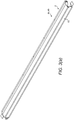
- Figures 3(a) to (c) illustrate a background illumination device 4a, b, for providing background illumination to the at least one detector 3a, b, in accordance with one embodiment of the present invention.
- the illumination device comprises a housing 6 which includes an elongate illumination chamber 7, which has an elongate illumination aperture 8, a light source 11 which extends along a length of the illumination chamber 7, and a light diffuser 15 which is disposed at the illumination aperture 8 and diffuses the light thereat.
- the illumination chamber 7 comprises a first, rear surface 21 and second and third, lower and upper surfaces 23, 25 which are disposed in spaced relation and extend forwardly from the rear surface 21 to the illumination aperture 8.
- the illumination chamber 7 has a length L, here of 1800 mm.
- the illumination chamber 7 has a depth D between the light source 11 and the diffuser 15, here of 70 mm.
- the depth D is less than 200 mm, optionally less than 150 mm, and optionally less than 100 mm.
- the illumination chamber 7 has a height H between the lower and upper surfaces 23, 25, here of 45 mm.
- the height H is less than 150 mm, optionally less than 120 mm, and optionally less than 100 mm.
- the light source 11 is disposed at or adjacent the rear surface 21 of the housing 6, extending therealong.
- the lower and upper surfaces 23, 25 have a diffuse finish, and the housing 6 provides an integrating box.
- the lower and upper surfaces 23, 25 could have a specular finish, and the housing 6 provides a mirror box.
- the lower and upper surfaces 23, 25 are disposed in substantially parallel relation.
- At least one of the lower and upper surfaces 23, 25 has a first region 40, and at least one second region 41 which has a different optical property to an optical property of the first region 40.
- the present inventors have recognized that, by altering the optical properties of at least one of the lower and upper surfaces 23, 25 of the illumination chamber 7, the profile of the delivered illumination can be controlled, both to accommodate variance in the light generated by the light source 11 and also to accommodate variance in the light profile of the at least one associated foreground illumination devices 5a-d, such that a substantially-uniform light profile can be presented at the field of view, here at the chute 2.
- At least one of the lower and upper surfaces 23, 25 has a plurality of second regions 41 of different optical properties to the optical properties of the first region 40.
- At least one of the lower and upper surfaces 23, 25 has a pair of second regions 41 of different optical properties to the optical properties of the first region 40, which are located to respective ones of rear and outward lateral sections of the at least one of the lower and upper surfaces 23, 25, adjacent the light source 11.
- the second regions 41 are spaced from one another by a distance d, here by a distance of 250 mm.
- the second regions 41 each have a length I, here of 775 mm.
- the length I is less than half of the length L of the illumination chamber 7.
- the second regions 41 are triangular is shape, and have a projection p, here of 18 mm, at the outer lateral edges of the illumination chamber 7, tapering inwardly to a central region of the illumination chamber 7.
- the second regions 41 could be regions of varying radial dimension, such as circles of varying diameter, so as to create a more complex stippled pattern.
- the projection p has a length of less than half of the depth D of the illumination chamber 7, optionally less than one-third of the illumination chamber 7, and optionally less than one-quarter of the illumination chamber 7.
- the first and second regions 40, 41 have a different color and/ or a different surface color and/or a different spectral reflectance, with the first region being made of or coated with a high-diffuse reflectance material, such as white paint and the at least one second region 41 being made of or coated with low reflectance material or coating, such as black paint. It will, however, be understood that the first and second regions 40, 41 could have any different colors or surface colors or spectral reflectances.
- first and second regions 40, 41 could have a different surface texture with a different scattering fraction and distribution.
- first and second regions 40, 41 could have a different color and/or different surface color and/or different spectral reflectance and/or different texture.
- each of the lower and upper surfaces 23, 25 has at least one second region 41 of different optical properties.
- the light source 11 is an elongate light-emitting diode (LED) light source which comprises a plurality of LEDs 51 spaced along a length thereof.
- LED light-emitting diode
- ones of the LEDs have different spectral output or color, so as to allow for control of the spectral output or color.
- selected ones or groups of ones of the LEDs 51 can be controlled independently so as to control the pitch and/or intensity of the LEDs 51, such as by varying the drive current.
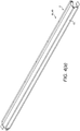
- Figures 4(a) to (c) illustrate a background illumination device 4a, b, for providing background illumination to the at least one detector 3a, b, in accordance with another embodiment of the present invention.
- the illumination device comprises a housing 6 which includes an elongate illumination chamber 7, which has an elongate illumination aperture 8, a light source 11 which extends along a length of the illumination chamber 7, and a light diffuser 15 which is disposed at the illumination aperture 8 and diffuses the light thereat.
- the illumination chamber 7 comprises a first, rear surface 21, second and third, lower and upper surfaces 23, 25 which are disposed in spaced relation and extend forwardly from the rear surface 21 to the illumination aperture 8, and fourth and fifth, side surfaces 27, 29, which define the lateral ends of the illumination chamber 7 and extend forwardly from the rear surface 21 to the illumination aperture 8.
- the illumination chamber 7 has a length L, here of 1800 mm.
- the illumination chamber 7 has a depth D between the light source 11 and the diffuser 15, here of 70 mm.
- the depth D is less than 200 mm, optionally less than 150 mm, and optionally less than 100 mm.
- the illumination chamber 7 has a height H between the lower and upper surfaces 23, 25, here of 45 mm.
- the height H is less than 150 mm, optionally less than 120 mm, and optionally less than 100 mm.
- the light source 11 is disposed at or adjacent the rear surface 21 of the housing 6, extending therealong.
- the lower and upper surfaces 23, 25 have a diffuse finish, and the housing 6 provides an integrating box.
- the lower and upper surfaces 23, 25 could have a specular finish, and the housing 6 provides a mirror box.
- the lower and upper surfaces 23, 25 are disposed in substantially parallel relation.
- lower and upper surfaces 23, 25 comprise a specular reflectance material or coating or a diffuse reflectance material or coating, such as white paint.
- Lower and upper surfaces 23, 25 may also comprise a material or coating that has any ratio of specular to diffuse reflectance.
- the lower and upper surfaces 23, 25 could have a color other than white or a reflectance that varies with wavelength.
- the lower and upper surfaces 23, 25 have optical properties which are matched to the light source 11, which may involve use of materials, coatings or surface finishes with spectral reflectance, low or high, matched to the light source 11.
- the rear and side surfaces 21, 27, 29 comprise a specular reflectance material or coating, a diffuse reflectance material or coating, such as white paint, or low reflectance material or coating, such as black paint.
- Rear and side surfaces 21, 27, 29 may also comprise a material or coating that has any ratio of specular to diffuse reflectance.
- the rear and side surfaces 21, 27, 29 could have a color other than white or black or have a reflectance that varies with wavelength or have a low reflectance.
- the lower and upper surfaces 23, 25 could have different optical properties to the rear and side surfaces 21, 27, 29.
- the light source 11 is an infra-red (IR) light-emitting diode (LED) light source with an emission spectrum within the near infra-red (NIR) and/or short-wave infra-red (SWIR) regions, encompassing wavelengths from about 700 nm to about 2.5 ⁇ m.
- IR infra-red
- NIR near infra-red
- SWIR short-wave infra-red
- the present inventors have recognized that the application of such an IR LED light source in an illumination box, which has controlled spectral reflectance, advantageously provides background illumination which allows for the discrimination of dark foreign matter from dark (acceptable) product.
- the light source comprises a plurality of LEDs 51 which are spaced along a length of the illumination chamber 7.
- selected ones or groups of ones of the LEDs 51 can be controlled independently so as to control the pitch and/or intensity of the LEDs 51, such as by varying the drive current.
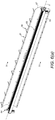
- Figures 5(a) to (c) illustrate a background illumination device 4a, b, for providing background illumination to the at least one detector 3a, b, in accordance with a further embodiment of the present invention.
- the illumination device comprises a housing 6 which includes an elongate illumination chamber 7, which has an elongate illumination aperture 8, a light source 11 which extends along a length of the illumination chamber 7, and a light diffuser 15 which is disposed at the illumination aperture 8 and diffuses the light thereat.
- the illumination chamber 7 comprises a first, rear surface 21, second and third, lower and upper surfaces 23, 25 which are disposed in spaced relation and extend forwardly from the rear surface 21 to the illumination aperture 8, and fourth and fifth, side surfaces 27, 29, which define the lateral ends of the illumination chamber 7 and extend forwardly from the rear surface 21 to the illumination aperture 8.
- the illumination chamber 7 has a length L, here of 1800 mm.
- the illumination chamber 7 has a depth D between the light source 11 and the diffuser 15, here of 70 mm.
- the depth D is less than 200 mm, optionally less than 150 mm, and optionally less than 100 mm.
- the illumination chamber 7 has a height H between the lower and upper surfaces 23, 25, here of 45 mm.
- the height H is less than 150 mm, optionally less than 120 mm, and optionally less than 100 mm.
- the light source 11 is disposed at or adjacent the rear surface 21 of the housing 6, extending therealong.
- the lower and upper surfaces 23, 25 have a diffuse finish, and the housing 6 provides an integrating box.
- the lower and upper surfaces 23, 25 could have a specular finish, and the housing 6 provides a mirror box.
- the lower and upper surfaces 23, 25 are disposed in substantially parallel relation.
- the lower and upper surfaces 23, 25 comprise a specular reflectance material or coating or are made of or coated with a diffuse reflectance material, such as white paint.
- Lower and upper surfaces 23, 25 may also comprise a material or coating that has any ratio of specular to diffuse reflectance.
- the lower and upper surfaces 23, 25 could have a color other than white or a reflectance that varies with wavelength.
- the rear and side surfaces 21, 27, 29 comprise a specular reflectance material or coating or are made of or coated with a diffuse reflectance material, such as white paint or are made of or coated with low reflectance material or coating, such as black paint.
- rear and side surfaces 21, 27, 29 could have a color other than white or black.
- the lower and upper surfaces 23, 25 could have a different surface texture to the rear and side surfaces 21, 27, 29.
- the light source 11 is a light-emitting diode (LED) light source which comprises a plurality of LEDs 51 which are spaced along a length of the illumination chamber 7.
- LED light-emitting diode
- the LEDs 51 comprise LEDs 51a-d of a plurality of different wavelengths or colors.
- the LEDs 51a-d have four different wavelengths or colors, but could have any number of two or greater.
- the LEDs 51a-d are blue, green, red and far-red in color.
- the LEDs 51a-d of each wavelength or color are connected to a common channel 52a-d, such that the LEDs 51a-d of one wavelength or color are switchable independently of the LEDs 51a-d of the other wavelengths or colors.
- the LEDs 51a-d are arranged on a plurality of rows 53a-d which extend along a length of the illumination chamber 7.
- the LEDs 51a-d are arranged on four rows 53a-d, but could have any number of two or greater.
- the LEDs 51a-d are arranged in substantially symmetrical relation about the longitudinal axis of the light source 11.
- the LEDs 51a-d of each wavelength or color are arranged on a plurality of different rows 53a-d which have symmetrical relation about the longitudinal axis of the light source 11, such that a substantially an equal number of LEDs 51a-d of each wavelength or color are arranged along the length of the light source 11.
- the present inventors have recognized an arrangement of the LEDs 51a-d of different wavelength or color which provides multi-wavelength or multi-color background illumination with a symmetrical profile, and yet allows for separation of the LEDs 51a-d, which enables distribution of the thermal load and also allows for the accommodation of other components between ones of the rows 53a-d. Furthermore, this arrangement of the LEDs 51a-d allows for independent switching.
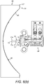
- Figures 6(a) to (g) illustrate a foreground illumination device 5a-d, for providing foreground illumination to the at least one detector 3a, b, in accordance with one embodiment of the present invention.
- the illumination device comprises a reflector 61 which provides a reflector surface 63, and a lighting assembly 64 which is disposed in front of the reflector surface 63 and provides light of a first wavelength to the reflector surface 63 for reflection thereby to a field of view of the at least one detector 3a, b.
- the reflector 61 is an elongate, linear reflector.
- the reflector 61 comprises a support 66 and a reflector element 67 which provides the reflector surface 63 and is attached to the support 66.
- the reflector element 67 is attached to the support 66 by folded tabs 68.
- the reflecting surface 63 is an elliptical surface.
- the reflector surface 63 may be made, for instance, from a material or coating that has high specular reflectance or from a material that has high-diffuse reflectance or from a material that has any scattering fraction and distribution.
- the lighting assembly 64 a first light source 70 which is disposed in front of the reflecting surface 63 and provides light of a first wavelength to the reflecting surface 63 of the reflector 61, and a second light source 71 of a second wavelength, different to the first wavelength, which is disposed in front of the reflecting surface 63 and provides light of a first wavelength to the reflecting surface 63 of the reflector 61.
- first and second light sources 70, 71 are disposed within and in symmetrical relation to the reflector 61, and so provide illumination of different wavelength which is co-incident at the field of view of the at least one detector 3a, b, as represented in Figure 6(g) .
- the first light source 70 is an incandescent light source emitting blackbody or greybody radiation with an emission spectrum within the visible, near infra-red (NIR) and/or short-wave infra-red (SWIR) regions.
- NIR near infra-red
- SWIR short-wave infra-red
- the first light source 70 provides light with a wavelength of from about 400 nm to about 2.5 ⁇ m, but light of other wavelengths can be provided in other embodiments.
- the first light source 70 is an incandescent light source.
- the first light source 70 comprises a plurality of incandescent lamps 72.
- the lamps 72 are arranged along a single row 73.
- the lamps 72 are disposed on or near a focal axis X (sometimes referred to as the optical axis or longitudinal axis) of the reflector 61.
- the lamps 72 comprise Xenon incandescent lamps, but could be other incandescent lamps, such as halogen lamps.
- the lamps 72 comprise axial filament lamps, but could be transverse filament lamps or festoons.
- the second light source 71 is a visible light source.
- the second light source 71 provides light with a wavelength of from about 400 nm to about 780 nm.
- the second light source 71 is a light-emitting diode (LED) light source.
- LED light-emitting diode
- the second light source 71 comprises a plurality of LEDs 75.
- the LEDs 75 are disposed on or near a focal axis X (sometimes referred to as the optical axis or longitudinal axis) of the reflector 61.
- the LEDs 75 are arranged along a plurality of rows 77a, b, which each extend along the length of the reflecting surface 63 and are arranged in spaced relation in a direction substantially parallel to the focal axis X of the reflector 61.
- the rows 77a, b are spaced in symmetrical relation to the focal axis X of the reflector 61.
- the LEDs 75 in the rows 77a, b are offset in staggered relation along the length of the second light source 71.
- the present inventors have recognized that, by providing the LEDs 75 in spaced, staggered rows 77a, b, the irradiance profiles of the LEDs 75 and the incandescent lamps 72 can be more closely matched.
Landscapes
- Physics & Mathematics (AREA)
- Chemical & Material Sciences (AREA)
- Health & Medical Sciences (AREA)
- Life Sciences & Earth Sciences (AREA)
- General Physics & Mathematics (AREA)
- Analytical Chemistry (AREA)
- Biochemistry (AREA)
- General Health & Medical Sciences (AREA)
- Spectroscopy & Molecular Physics (AREA)
- Immunology (AREA)
- Pathology (AREA)
- Engineering & Computer Science (AREA)
- Food Science & Technology (AREA)
- Medicinal Chemistry (AREA)
- Investigating Materials By The Use Of Optical Means Adapted For Particular Applications (AREA)
- Investigating Or Analysing Materials By Optical Means (AREA)
- Non-Portable Lighting Devices Or Systems Thereof (AREA)
- Sorting Of Articles (AREA)
Description
- The present invention relates to sorting or classifying machines, and illumination devices therefor, in particular for foreground illumination, especially in the sorting or classifying of particulate product, such as foodstuffs or vegetables.
- Various illumination devices exist for providing background or foreground illumination in sorting or classifying machines, such as disclosed in
EP-A-2324935 ,EP-A-2671651 ,CN-A0104368540 CN-A-104941926 ,GB-A-2411947 JP-A-2012/096211 JP-A-2015/078912 US-A-6784996 ,US-A-7339660 ,US-A-9000319 US-A-9074756 US-9146190 US-A-9156065 US-A-2012/0097583 ,US-A-2013/0126396 ,US-A-2014/0333755 ,US-A-2015/0377427 ,WO-A-2002/085547 andWO-A-2013/021154 . - It is an aim of the present invention to provide improved sorting or classifying machines, and illumination devices therefor, in particular for foreground illumination, especially in the sorting or classifying of particulate product, such as foodstuffs or vegetables.
- The present invention provides a sorting or classifying apparatus comprising an illumination device for providing foreground illumination according to
claim 1. - In one embodiment (i) the reflector is an elongate, linear reflector, and optionally the reflecting surface is an elliptical surface; (ii) the first and second light sources are disposed within the reflection envelope of the reflector and in symmetrical relation to the reflector, thereby providing co-incident illumination of different wavelengths; and/or (iii) the first light source provides light with a wavelength of from about 400 nm to about 2.5 µm, and the second light source provides light with a wavelength of from about 400 nm to about 780 nm.
- In one embodiment the incandescent lamps are arranged along a single row.
- In one embodiment the light elements are arranged in a plurality of rows in symmetrical, spaced relation to the focal axis of the reflector, optionally the light elements in the rows are offset in staggered relation along the length of the second light source.
- In another aspect the apparatus further comprises an illumination box for providing background or reference illumination, the illumination box comprising a housing which includes an elongate illumination chamber having an illumination aperture, the illumination chamber comprising a first, rear surface and second and third, lower and upper surfaces which are disposed in spaced relation and extend forwardly from the rear surface to the illumination aperture and are disposed in substantially parallel relation, a light diffuser which is disposed at the illumination aperture and a light source which extends along a length of the illumination chamber, wherein at least one of the lower and upper surfaces, optionally both the lower and upper surfaces, has a first region and at least one second region which has different optical properties to optical properties of the first region such that the illumination box accommodates for variance in light generated by the light source of the illumination box and also for variance in light generated by the foreground illumination device.
- In one embodiment (i) the light source of the illumination box is an infra-red (IR) light-emitting diode (LED) light source with an emission spectrum within the near infra-red (NIR) and/or short-wave infra-red (SWIR) regions, encompassing wavelengths of from about 700 nm to about 2.5 µm; (ii) the light source of the illumination box has an emission spectrum encompassing wavelengths of from about 700 nm to about 2.5 µm; and/or (iii) the light source of the illumination box is disposed at or adjacent the rear surface, extending therealong.
- In one embodiment (i) the illumination chamber has a depth between the light source of the illumination box and the illumination aperture of less than 200 mm, preferably less than 150 mm, and most preferably less than 100 mm; (ii) the illumination chamber has a height between the lower and upper surfaces of less than 150 mm, preferably less than 120 mm, and most preferably less than 100 mm; (iii) the lower and upper surfaces have a diffuse finish and the housing provides an integrating box, or the lower and upper surfaces have a specular finish and the housing provides a mirror box; (iv) the lower and upper surfaces comprise a specular reflectance material or coating or a diffuse reflectance material or coating, optionally painted with white paint; and/or (v) at least one of the lower and upper surfaces has a plurality of second regions of different optical properties to optical properties of the first region.
- In one embodiment at least one of the lower and upper surfaces has a plurality of second regions of different optical properties to optical properties of the first region, optionally: (i) at least one of the lower and upper surfaces has a pair of second regions of different optical properties to optical properties of the first region, which are located to respective ones of rear and outward lateral sections of the at least one of the lower and upper surfaces, adjacent the light source of the illumination box; (ii) the second regions are spaced from one another by a distance; (iii) the second regions each have a length which is less than half of the length of the illumination chamber; and/or (iv) the second regions are substantially triangular in shape, and have a projection at the outer lateral edges of the illumination chamber, tapering inwardly to a central region of the illumination chamber, optionally the projection has a length of less than half of the depth of the illumination chamber, preferably less than one-third of the depth of the illumination chamber, and most preferably less than one-quarter of the depth of the illumination chamber.
- In one embodiment (i) the first and second regions have a different surface color and/or a different spectral reflectance, optionally the first region being made of or coated with a diffuse reflectance material, optionally white paint, and the at least one second region being made of or coated with low reflectance material, optionally black paint; and/or (ii) the first and second regions have different optical properties.
- In one embodiment (i) the rear surface comprises a specular reflectance material or coating or a diffuse reflectance material or coating, optionally painted with white paint, or a low reflectance material or coating, optionally painted with black paint; and/or (ii) the rear surface has different optical properties to optical properties of the lower and upper surfaces.
- In one embodiment the illumination chamber further comprises fourth and fifth, side surfaces which define the lateral ends of the illumination chamber, optionally: (i) the side surfaces comprise a specular reflectance material or coating or a diffuse reflectance material or coating, optionally painted with white paint, or a low reflectance material or coating, optionally painted with black paint; and/or (ii) the side surfaces have different optical properties to optical properties of the lower and upper surfaces.
- In one embodiment the light source of the illumination box is an elongate light-emitting diode (LED) light source which comprises a plurality of light-emitting diodes (LEDs) spaced along a length thereof, optionally ones or groups of ones of the LEDs are of different wavelengths or colors, optionally selected ones or groups of ones of the LEDs can be controlled independently so as to control the pitch and/or intensity of the LEDs.
- In a further aspect the apparatus further comprises an illumination device for providing background or reference illumination, the background or reference illumination device comprising a diffuser and an elongate light source which comprises a two-dimensional array of separated LEDs of a plurality of different wavelengths or colors, wherein the LEDs are arranged in substantially symmetrical relation to opposite sides of a longitudinal axis of the light source of the background or reference illumination device and the LEDs of each wavelength or color are connected to a common channel, such that the LEDs of one wavelength or color are switchable independently of the LEDs of other wavelengths or colors, such that a symmetrical illumination profile is provided.
- In one embodiment (i) the LEDs are of three or more different wavelengths or colors; and/or (ii) the LEDs are arranged in a plurality of rows which extend in substantially parallel relation to the longitudinal axis of the light source of the background or reference illumination device, optionally the LEDs are arranged in three or more rows.
- In a still further aspect the apparatus further comprises an illumination box for providing background or reference illumination, the illumination box comprising a housing which includes an elongate illumination chamber having an illumination aperture, the illumination chamber comprising a first, rear surface and second and third, lower and upper surfaces which are disposed in spaced relation and extend forwardly from the rear surface to the illumination aperture and are disposed in substantially parallel relation, and a light source which extends along a length of the illumination chamber, the light source of the illumination box being an infra-red (IR) light-emitting diode (LED) light source, optionally having an emission spectrum within the near infra-red (NIR) and/or short-wave infra-red (SWIR) regions.
- 'Optical properties' may comprise, for instance, spectral reflectivities, surface finishes, surface textures, scattering fractions (e.g. specular properties), scattering distributions, varying degrees of diffuseness and/or ratio of specular to diffuse reflectance.
- Preferred embodiments of the present invention will now be described herein below by way of example only with references to the accompanying drawings, in which:
-
Figure 1 illustrates a perspective view of a sorting or classifying machine in accordance with one embodiment of the present invention; -
Figure 2 illustrates a side view of the sorting or classifying machine ofFigure 1 ; -
Figure 3(a) illustrates a perspective view of a background illumination device in accordance with one embodiment of the present invention; -
Figure 3(b) illustrates a part cut-away front view of the illumination device ofFigure 3(a) ; -
Figure 3(c) illustrates a longitudinal sectional view (along section I-I inFigure 3(b) ) of the illumination device ofFigure 3(a) ; -
Figure 4(a) illustrates a perspective view of a background illumination device in accordance with another embodiment of the present invention; -
Figure 4(b) illustrates a part cut-away front view of the illumination device ofFigure 4(a) ; -
Figure 4(c) illustrates a longitudinal sectional view (along section II-II inFigure 4(b) ) of the illumination device ofFigure 4(a) ; -
Figure 5(a) illustrates a perspective view of a background illumination device in accordance with a further embodiment of the present invention; -
Figure 5(b) illustrates a part cut-away front view of the illumination device ofFigure 5(a) ; -
Figure 5(c) illustrates a longitudinal sectional view (along section III-III inFigure 5(b) ) of the illumination device ofFigure 5(a) ; -
Figure 5(d) illustrates a fragmentary view of the light source of the illumination device ofFigure 5(a) ; -
Figure 6(a) illustrates a perspective view of a foreground illumination device in accordance with one embodiment of the present invention; -
Figure 6(b) illustrates a vertical sectional view (along section IV-IV inFigure 6(a) ) of the illumination device ofFigure 6(a) ; -
Figure 6(c) illustrates a front view of the light assembly of the illumination device ofFigure 6(a) ; -
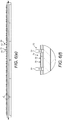
Figure 6(d) illustrates in enlarged scale a fragmentary front view (detail Y inFigure 6(c) ) of the light assembly ofFigure 6(c) ; -
Figure 6(e) illustrates a longitudinal sectional view (along section V-V inFigure 6(c) ) of the light assembly of the illumination device ofFigure 6(a) ; -
Figure 6(f) illustrates in enlarged scale a fragmentary longitudinal sectional view (detail Z, along section V-V inFigure 6(c) ) of the light assembly ofFigure 6(c) ; and -
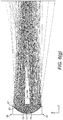
Figure 6(g) illustrates a ray diagram for the light profile as developed by the illumination device ofFigure 6(a) . -
Figures 1 and2 illustrate a sorting machine in accordance with one embodiment of the present invention. - The sorting or classifying machine comprises a
housing 1, achute 2 which is supported by thehousing 1 and to which a flow of particulate product is delivered, typically from an infeed vibrator, at least onedetector 3a, b for detecting product as delivered on and/or from thechute 2, at least onebackground illumination device 4a, b for providing background or reference illumination to a field of view of the at least onedetector 3a, b, and at least oneforeground illumination device 5a-d for providing foreground illumination to a field of view of the at least onedetector 3a, b. -
Figures 3(a) to (c) illustrate abackground illumination device 4a, b, for providing background illumination to the at least onedetector 3a, b, in accordance with one embodiment of the present invention. - The illumination device comprises a
housing 6 which includes anelongate illumination chamber 7, which has anelongate illumination aperture 8, alight source 11 which extends along a length of theillumination chamber 7, and alight diffuser 15 which is disposed at theillumination aperture 8 and diffuses the light thereat. - In this embodiment the
illumination chamber 7 comprises a first,rear surface 21 and second and third, lower andupper surfaces rear surface 21 to theillumination aperture 8. - In this embodiment the
illumination chamber 7 has a length L, here of 1800 mm. - In this embodiment the
illumination chamber 7 has a depth D between thelight source 11 and thediffuser 15, here of 70 mm. - In one embodiment the depth D is less than 200 mm, optionally less than 150 mm, and optionally less than 100 mm.
- In this embodiment the
illumination chamber 7 has a height H between the lower andupper surfaces - In one embodiment the height H is less than 150 mm, optionally less than 120 mm, and optionally less than 100 mm.
- In this embodiment the
light source 11 is disposed at or adjacent therear surface 21 of thehousing 6, extending therealong. - In this embodiment the lower and
upper surfaces housing 6 provides an integrating box. - In an alternative embodiment the lower and
upper surfaces housing 6 provides a mirror box. - In this embodiment the lower and
upper surfaces - In this embodiment at least one of the lower and
upper surfaces second region 41 which has a different optical property to an optical property of the first region 40. - The present inventors have recognized that, by altering the optical properties of at least one of the lower and
upper surfaces illumination chamber 7, the profile of the delivered illumination can be controlled, both to accommodate variance in the light generated by thelight source 11 and also to accommodate variance in the light profile of the at least one associatedforeground illumination devices 5a-d, such that a substantially-uniform light profile can be presented at the field of view, here at thechute 2. - In this embodiment at least one of the lower and
upper surfaces second regions 41 of different optical properties to the optical properties of the first region 40. - In this embodiment at least one of the lower and
upper surfaces second regions 41 of different optical properties to the optical properties of the first region 40, which are located to respective ones of rear and outward lateral sections of the at least one of the lower andupper surfaces light source 11. - In this embodiment the
second regions 41 are spaced from one another by a distance d, here by a distance of 250 mm. - In this embodiment the
second regions 41 each have a length I, here of 775 mm. - In this embodiment the length I is less than half of the length L of the
illumination chamber 7. - In this embodiment the
second regions 41 are triangular is shape, and have a projection p, here of 18 mm, at the outer lateral edges of theillumination chamber 7, tapering inwardly to a central region of theillumination chamber 7. - In an alternative embodiment the
second regions 41 could be regions of varying radial dimension, such as circles of varying diameter, so as to create a more complex stippled pattern. - In this embodiment the projection p has a length of less than half of the depth D of the
illumination chamber 7, optionally less than one-third of theillumination chamber 7, and optionally less than one-quarter of theillumination chamber 7. - In this embodiment the first and
second regions 40, 41 have a different color and/ or a different surface color and/or a different spectral reflectance, with the first region being made of or coated with a high-diffuse reflectance material, such as white paint and the at least onesecond region 41 being made of or coated with low reflectance material or coating, such as black paint. It will, however, be understood that the first andsecond regions 40, 41 could have any different colors or surface colors or spectral reflectances. - In another embodiment the first and
second regions 40, 41 could have a different surface texture with a different scattering fraction and distribution. - In one embodiment the first and
second regions 40, 41 could have a different color and/or different surface color and/or different spectral reflectance and/or different texture. - In this embodiment each of the lower and
upper surfaces second region 41 of different optical properties. - In this embodiment the
light source 11 is an elongate light-emitting diode (LED) light source which comprises a plurality ofLEDs 51 spaced along a length thereof. - In this embodiment ones of the LEDs have different spectral output or color, so as to allow for control of the spectral output or color.
- In one embodiment selected ones or groups of ones of the
LEDs 51 can be controlled independently so as to control the pitch and/or intensity of theLEDs 51, such as by varying the drive current. -
Figures 4(a) to (c) illustrate abackground illumination device 4a, b, for providing background illumination to the at least onedetector 3a, b, in accordance with another embodiment of the present invention. - The illumination device comprises a
housing 6 which includes anelongate illumination chamber 7, which has anelongate illumination aperture 8, alight source 11 which extends along a length of theillumination chamber 7, and alight diffuser 15 which is disposed at theillumination aperture 8 and diffuses the light thereat. - In this embodiment the
illumination chamber 7 comprises a first,rear surface 21, second and third, lower andupper surfaces rear surface 21 to theillumination aperture 8, and fourth and fifth, side surfaces 27, 29, which define the lateral ends of theillumination chamber 7 and extend forwardly from therear surface 21 to theillumination aperture 8. - In this embodiment the
illumination chamber 7 has a length L, here of 1800 mm. - In this embodiment the
illumination chamber 7 has a depth D between thelight source 11 and thediffuser 15, here of 70 mm. - In one embodiment the depth D is less than 200 mm, optionally less than 150 mm, and optionally less than 100 mm.
- In this embodiment the
illumination chamber 7 has a height H between the lower andupper surfaces - In one embodiment the height H is less than 150 mm, optionally less than 120 mm, and optionally less than 100 mm.
- In this embodiment the
light source 11 is disposed at or adjacent therear surface 21 of thehousing 6, extending therealong. - In this embodiment the lower and
upper surfaces housing 6 provides an integrating box. - In an alternative embodiment the lower and
upper surfaces housing 6 provides a mirror box. - In this embodiment the lower and
upper surfaces - In this embodiment the lower and
upper surfaces upper surfaces - In one alternative embodiment the lower and
upper surfaces - In one embodiment the lower and
upper surfaces light source 11, which may involve use of materials, coatings or surface finishes with spectral reflectance, low or high, matched to thelight source 11. - In this embodiment the rear and side surfaces 21, 27, 29 comprise a specular reflectance material or coating, a diffuse reflectance material or coating, such as white paint, or low reflectance material or coating, such as black paint. Rear and side surfaces 21, 27, 29 may also comprise a material or coating that has any ratio of specular to diffuse reflectance.
- In one alternative embodiment the rear and side surfaces 21, 27, 29 could have a color other than white or black or have a reflectance that varies with wavelength or have a low reflectance.
- In one embodiment the lower and
upper surfaces - In this embodiment the
light source 11 is an infra-red (IR) light-emitting diode (LED) light source with an emission spectrum within the near infra-red (NIR) and/or short-wave infra-red (SWIR) regions, encompassing wavelengths from about 700 nm to about 2.5 µm. - The present inventors have recognized that the application of such an IR LED light source in an illumination box, which has controlled spectral reflectance, advantageously provides background illumination which allows for the discrimination of dark foreign matter from dark (acceptable) product.
- In this embodiment the light source comprises a plurality of
LEDs 51 which are spaced along a length of theillumination chamber 7. - In one embodiment selected ones or groups of ones of the
LEDs 51 can be controlled independently so as to control the pitch and/or intensity of theLEDs 51, such as by varying the drive current. -
Figures 5(a) to (c) illustrate abackground illumination device 4a, b, for providing background illumination to the at least onedetector 3a, b, in accordance with a further embodiment of the present invention. - The illumination device comprises a
housing 6 which includes anelongate illumination chamber 7, which has anelongate illumination aperture 8, alight source 11 which extends along a length of theillumination chamber 7, and alight diffuser 15 which is disposed at theillumination aperture 8 and diffuses the light thereat. - In this embodiment the
illumination chamber 7 comprises a first,rear surface 21, second and third, lower andupper surfaces rear surface 21 to theillumination aperture 8, and fourth and fifth, side surfaces 27, 29, which define the lateral ends of theillumination chamber 7 and extend forwardly from therear surface 21 to theillumination aperture 8. - In this embodiment the
illumination chamber 7 has a length L, here of 1800 mm. - In this embodiment the
illumination chamber 7 has a depth D between thelight source 11 and thediffuser 15, here of 70 mm. - In one embodiment the depth D is less than 200 mm, optionally less than 150 mm, and optionally less than 100 mm.
- In this embodiment the
illumination chamber 7 has a height H between the lower andupper surfaces - In one embodiment the height H is less than 150 mm, optionally less than 120 mm, and optionally less than 100 mm.
- In this embodiment the
light source 11 is disposed at or adjacent therear surface 21 of thehousing 6, extending therealong. - In this embodiment the lower and
upper surfaces housing 6 provides an integrating box. - In an alternative embodiment the lower and
upper surfaces housing 6 provides a mirror box. - In this embodiment the lower and
upper surfaces - In this embodiment the lower and
upper surfaces upper surfaces - In one alternative embodiment the lower and
upper surfaces - In this embodiment the rear and side surfaces 21, 27, 29 comprise a specular reflectance material or coating or are made of or coated with a diffuse reflectance material, such as white paint or are made of or coated with low reflectance material or coating, such as black paint.
- In one alternative embodiment the rear and side surfaces 21, 27, 29 could have a color other than white or black.
- In one embodiment the lower and
upper surfaces - In this embodiment the
light source 11 is a light-emitting diode (LED) light source which comprises a plurality ofLEDs 51 which are spaced along a length of theillumination chamber 7. - In this embodiment the
LEDs 51 compriseLEDs 51a-d of a plurality of different wavelengths or colors. - In this embodiment the
LEDs 51a-d have four different wavelengths or colors, but could have any number of two or greater. - In this embodiment the
LEDs 51a-d are blue, green, red and far-red in color. - In this embodiment the
LEDs 51a-d of each wavelength or color are connected to acommon channel 52a-d, such that theLEDs 51a-d of one wavelength or color are switchable independently of theLEDs 51a-d of the other wavelengths or colors. - In this embodiment the
LEDs 51a-d are arranged on a plurality ofrows 53a-d which extend along a length of theillumination chamber 7. - In this embodiment the
LEDs 51a-d are arranged on fourrows 53a-d, but could have any number of two or greater. - In this embodiment the
LEDs 51a-d are arranged in substantially symmetrical relation about the longitudinal axis of thelight source 11. - In this embodiment the
LEDs 51a-d of each wavelength or color are arranged on a plurality ofdifferent rows 53a-d which have symmetrical relation about the longitudinal axis of thelight source 11, such that a substantially an equal number ofLEDs 51a-d of each wavelength or color are arranged along the length of thelight source 11. - The present inventors have recognized an arrangement of the
LEDs 51a-d of different wavelength or color which provides multi-wavelength or multi-color background illumination with a symmetrical profile, and yet allows for separation of theLEDs 51a-d, which enables distribution of the thermal load and also allows for the accommodation of other components between ones of therows 53a-d. Furthermore, this arrangement of theLEDs 51a-d allows for independent switching. -
Figures 6(a) to (g) illustrate aforeground illumination device 5a-d, for providing foreground illumination to the at least onedetector 3a, b, in accordance with one embodiment of the present invention. - The illumination device comprises a
reflector 61 which provides areflector surface 63, and alighting assembly 64 which is disposed in front of thereflector surface 63 and provides light of a first wavelength to thereflector surface 63 for reflection thereby to a field of view of the at least onedetector 3a, b. - In this embodiment the
reflector 61 is an elongate, linear reflector. - In this embodiment the
reflector 61 comprises asupport 66 and areflector element 67 which provides thereflector surface 63 and is attached to thesupport 66. - In this this embodiment the
reflector element 67 is attached to thesupport 66 by foldedtabs 68. - In this embodiment the reflecting
surface 63 is an elliptical surface. Thereflector surface 63 may be made, for instance, from a material or coating that has high specular reflectance or from a material that has high-diffuse reflectance or from a material that has any scattering fraction and distribution. - In this embodiment the lighting assembly 64 a
first light source 70 which is disposed in front of the reflectingsurface 63 and provides light of a first wavelength to the reflectingsurface 63 of thereflector 61, and a secondlight source 71 of a second wavelength, different to the first wavelength, which is disposed in front of the reflectingsurface 63 and provides light of a first wavelength to the reflectingsurface 63 of thereflector 61. - In this embodiment the first and second
light sources reflector 61, and so provide illumination of different wavelength which is co-incident at the field of view of the at least onedetector 3a, b, as represented inFigure 6(g) . - In this embodiment the
first light source 70 is an incandescent light source emitting blackbody or greybody radiation with an emission spectrum within the visible, near infra-red (NIR) and/or short-wave infra-red (SWIR) regions. - In this embodiment the
first light source 70 provides light with a wavelength of from about 400 nm to about 2.5 µm, but light of other wavelengths can be provided in other embodiments. - In this embodiment the
first light source 70 is an incandescent light source. - In this embodiment the
first light source 70 comprises a plurality ofincandescent lamps 72. - In this embodiment the
lamps 72 are arranged along asingle row 73. - In this embodiment the
lamps 72 are disposed on or near a focal axis X (sometimes referred to as the optical axis or longitudinal axis) of thereflector 61. - In this embodiment the
lamps 72 comprise Xenon incandescent lamps, but could be other incandescent lamps, such as halogen lamps. - In this embodiment the
lamps 72 comprise axial filament lamps, but could be transverse filament lamps or festoons. - In this embodiment the second
light source 71 is a visible light source. - In this embodiment the second
light source 71 provides light with a wavelength of from about 400 nm to about 780 nm. - In this embodiment the second
light source 71 is a light-emitting diode (LED) light source. - In this embodiment the second
light source 71 comprises a plurality ofLEDs 75. - In this embodiment the
LEDs 75 are disposed on or near a focal axis X (sometimes referred to as the optical axis or longitudinal axis) of thereflector 61. - In this embodiment the
LEDs 75 are arranged along a plurality ofrows 77a, b, which each extend along the length of the reflectingsurface 63 and are arranged in spaced relation in a direction substantially parallel to the focal axis X of thereflector 61. - In this embodiment the
rows 77a, b are spaced in symmetrical relation to the focal axis X of thereflector 61. - In this embodiment the
LEDs 75 in therows 77a, b are offset in staggered relation along the length of the secondlight source 71. - The present inventors have recognized that, by providing the
LEDs 75 in spaced,staggered rows 77a, b, the irradiance profiles of theLEDs 75 and theincandescent lamps 72 can be more closely matched. - Finally, it will be understood that the present invention has been described in its preferred embodiments and can be modified in many different ways without departing from the scope of the invention as defined by the appended claims.
Claims (15)
- A sorting or classifying apparatus comprising an illumination device (5a-d) for providing foreground illumination, the foreground illumination device (5a-d) comprising a reflector (61) which has a reflecting surface (63) providing a reflection envelope, a first light source (70) which is disposed in spaced relation in front of and faces the reflecting surface (63) and provides light of a first spectral output to the reflecting surface (63) for reflection thereby, the first light source (70) comprising a plurality of incandescent lamps (72) which are disposed on or near a focal axis (X) of the reflector (61), and a second light source (71) which is disposed in spaced relation in front of and faces the reflecting surface (63) and provides light of a second spectral output, different to the first spectral output, to the reflecting surface (63) for reflection thereby, the second light source (71) comprising a plurality of light elements (75), optionally light-emitting diodes (LEDs), arranged along at least one row (77a, b) which extends along the length of the reflecting surface (63) and is arranged in a direction substantially parallel to the focal axis (X) of the reflector (61), optionally the first light source (70) is a source of near infra-red (NIR) light and the second light source (71) is a source of visible-spectrum light.
- The apparatus of claim 1, wherein:(i) the reflector (61) is an elongate, linear reflector, and optionally the reflecting surface (63) is an elliptical surface;(ii) the first and second light sources (70, 71) are disposed within the reflection envelope of the reflector (61) and in symmetrical relation to the reflector (61), thereby providing co-incident illumination of different wavelengths; and/or(iii) the first light source (70) provides light with a wavelength of from about 400 nm to about 2.5 µm, and the second light source (71) provides light with a wavelength of from about 400 nm to about 780 nm.
- The apparatus of claim 1 or 2, wherein the incandescent lamps (72) are arranged along a single row (73).
- The apparatus of any of claims 1 to 3, wherein the light elements (75) are arranged in a plurality of rows (77a, b) in symmetrical, spaced relation to the focal axis (X) of the reflector (61), optionally the light elements (75) in the rows (77a, b) are offset in staggered relation along the length of the second light source (71).
- The apparatus of any of claims 1 to 4, further comprising an illumination box for providing background or reference illumination, the illumination box comprising a housing (6) which includes an elongate illumination chamber (7) having an illumination aperture (8), the illumination chamber (7) comprising a first, rear surface (21) and second and third, lower and upper surfaces (23, 25) which are disposed in spaced relation and extend forwardly from the rear surface (21) to the illumination aperture (8) and are disposed in substantially parallel relation, a light diffuser (15) which is disposed at the illumination aperture (8) and a light source (11) which extends along a length of the illumination chamber (7), wherein at least one of the lower and upper surfaces (23, 25), optionally both the lower and upper surfaces (23, 25), has a first region (40) and at least one second region (41) which has different optical properties to optical properties of the first region (40) such that the illumination box accommodates for variance in light generated by the light source (11) of the illumination box and also for variance in light generated by the foreground illumination device (5a-d).
- The apparatus of claim 5, wherein:(i) the light source (11) of the illumination box is an infra-red (IR) light-emitting diode (LED) light source with an emission spectrum within the near infra-red (NIR) and/or short-wave infra-red (SWIR) regions, encompassing wavelengths of from about 700 nm to about 2.5 µm;(ii) the light source (11) of the illumination box has an emission spectrum encompassing wavelengths of from about 700 nm to about 2.5 µm; and/or(iii) the light source (11) of the illumination box is disposed at or adjacent the rear surface (21), extending therealong.
- The apparatus of claim 5 or 6, wherein:(i) the illumination chamber (7) has a depth (D) between the light source (11) of the illumination box and the illumination aperture (8) of less than 200 mm, preferably less than 150 mm, and most preferably less than 100 mm;(ii) the illumination chamber (7) has a height (H) between the lower and upper surfaces (23, 25) of less than 150 mm, preferably less than 120 mm, and most preferably less than 100 mm;(iii) the lower and upper surfaces (23, 25) have a diffuse finish and the housing (6) provides an integrating box, or the lower and upper surfaces (23, 25) have a specular finish and the housing (6) provides a mirror box;(iv) the lower and upper surfaces (23, 25) comprise a specular reflectance material or coating or a diffuse reflectance material or coating, optionally painted with white paint; and/or(v) at least one of the lower and upper surfaces (23, 25) has a plurality of second regions (41) of different optical properties to optical properties of the first region (40).
- The apparatus of any of claims 5 to 7, wherein at least one of the lower and upper surfaces (23, 25) has a plurality of second regions (41) of different optical properties to optical properties of the first region (40), optionally:(i) at least one of the lower and upper surfaces (23, 25) has a pair of second regions (41) of different optical properties to optical properties of the first region (40), which are located to respective ones of rear and outward lateral sections of the at least one of the lower and upper surfaces (23, 25), adjacent the light source (11) of the illumination box;(ii) the second regions (41) are spaced from one another by a distance (d);(iii) the second regions (41) each have a length (I) which is less than half of the length (L) of the illumination chamber (7); and/or(iv) the second regions (41) are substantially triangular in shape, and have a projection (p) at the outer lateral edges of the illumination chamber (7), tapering inwardly to a central region of the illumination chamber (7), optionally the projection (p) has a length of less than half of the depth (D) of the illumination chamber (7), preferably less than one-third of the depth (D) of the illumination chamber (7), and most preferably less than one-quarter of the depth (D) of the illumination chamber (7).
- The apparatus of any of claims 5 to 8, wherein:(i) the first and second regions (40, 41) have a different surface color and/or a different spectral reflectance, optionally the first region (40) being made of or coated with a diffuse reflectance material, optionally white paint, and the at least one second region (41) being made of or coated with low reflectance material, optionally black paint; and/or(ii) the first and second regions (40, 41) have different optical properties.
- The apparatus of any of claims 5 to 9, wherein:(i) the rear surface (21) comprises a specular reflectance material or coating or a diffuse reflectance material or coating, optionally painted with white paint, or a low reflectance material or coating, optionally painted with black paint; and/or(ii) the rear surface (21) has different optical properties to optical properties of the lower and upper surfaces (23, 25).
- The apparatus of any of claims 5 to 10, wherein the illumination chamber (7) further comprises fourth and fifth, side surfaces (27, 29) which define the lateral ends of the illumination chamber (7), optionally:(i) the side surfaces (27, 29) comprise a specular reflectance material or coating or a diffuse reflectance material or coating, optionally painted with white paint, or a low reflectance material or coating, optionally painted with black paint; and/or(ii) the side surfaces (27, 29) have different optical properties to optical properties of the lower and upper surfaces (23, 25).
- The apparatus of any of claims 5 to 11, wherein the light source (11) of the illumination box is an elongate light-emitting diode (LED) light source which comprises a plurality of light-emitting diodes (LEDs) (51) spaced along a length thereof, optionally ones or groups of ones of the LEDs (51) are of different wavelengths or colors, optionally selected ones or groups of ones of the LEDs (51) can be controlled independently so as to control the pitch and/or intensity of the LEDs (51).
- The apparatus of any of claims 1 to 4, further comprising an illumination device (4a, b) for providing background or reference illumination, the background or reference illumination device (4a, b) comprising a diffuser (15) and an elongate light source (11) which comprises a two-dimensional array of separated LEDs (51a-d) of a plurality of different wavelengths or colors, wherein the LEDs (51a-d) are arranged in substantially symmetrical relation to opposite sides of a longitudinal axis of the light source (11) of the background or reference illumination device (4a, b) and the LEDs (51a-d) of each wavelength or color are connected to a common channel (52a-d), such that the LEDs (51a-d) of one wavelength or color are switchable independently of the LEDs (51a-d) of other wavelengths or colors, such that a symmetrical illumination profile is provided.
- The apparatus of claim 13, wherein:(i) the LEDs (51a-d) are of three or more different wavelengths or colors; and/or(ii) the LEDs (51a-d) are arranged in a plurality of rows (53a-d) which extend in substantially parallel relation to the longitudinal axis of the light source (11) of the background or reference illumination device (4a, b), optionally the LEDs (51a-d) are arranged in three or more rows (53a-d).
- The apparatus of any of claims 1 to 4, further comprising an illumination box for providing background or reference illumination, the illumination box comprising a housing (6) which includes an elongate illumination chamber (7) having an illumination aperture (8), the illumination chamber (7) comprising a first, rear surface (21) and second and third, lower and upper surfaces (23, 25) which are disposed in spaced relation and extend forwardly from the rear surface (21) to the illumination aperture (8) and are disposed in substantially parallel relation, and a light source (11) which extends along a length of the illumination chamber (7), the light source (11) of the illumination box being an infra-red (IR) light-emitting diode (LED) light source, optionally having an emission spectrum within the near infra-red (NIR) and/or short-wave infra-red (SWIR) regions.
Applications Claiming Priority (2)
| Application Number | Priority Date | Filing Date | Title |
|---|---|---|---|
| EP16176769.4A EP3263233A1 (en) | 2016-06-28 | 2016-06-28 | Illumination devices |
| PCT/EP2017/066070 WO2018002185A1 (en) | 2016-06-28 | 2017-06-28 | Sorting or classifying apparatus |
Publications (2)
| Publication Number | Publication Date |
|---|---|
| EP3475002A1 EP3475002A1 (en) | 2019-05-01 |
| EP3475002B1 true EP3475002B1 (en) | 2020-10-14 |
Family
ID=56372741
Family Applications (2)
| Application Number | Title | Priority Date | Filing Date |
|---|---|---|---|
| EP16176769.4A Withdrawn EP3263233A1 (en) | 2016-06-28 | 2016-06-28 | Illumination devices |
| EP17733842.3A Active EP3475002B1 (en) | 2016-06-28 | 2017-06-28 | Sorting or classifying apparatus |
Family Applications Before (1)
| Application Number | Title | Priority Date | Filing Date |
|---|---|---|---|
| EP16176769.4A Withdrawn EP3263233A1 (en) | 2016-06-28 | 2016-06-28 | Illumination devices |
Country Status (5)
| Country | Link |
|---|---|
| US (1) | US10987701B2 (en) |
| EP (2) | EP3263233A1 (en) |
| CL (1) | CL2018003825A1 (en) |
| ES (1) | ES2835078T3 (en) |
| WO (1) | WO2018002185A1 (en) |
Families Citing this family (1)
| Publication number | Priority date | Publication date | Assignee | Title |
|---|---|---|---|---|
| CN113510109B (en) * | 2021-04-23 | 2022-10-14 | 安徽捷泰智能科技有限公司 | Channel surface repairing device for color sorter |
Family Cites Families (43)
| Publication number | Priority date | Publication date | Assignee | Title |
|---|---|---|---|---|
| GB2151018B (en) * | 1983-12-06 | 1987-07-22 | Gunsons Sortex Ltd | Sorting machine and method |
| US5440127A (en) * | 1993-05-17 | 1995-08-08 | Simco/Ramic Corporation | Method and apparatus for illuminating target specimens in inspection systems |
| IES66928B2 (en) * | 1994-07-25 | 1996-02-07 | Oseney Ltd | Optical inspection system |
| EP1046196B9 (en) * | 1998-09-28 | 2013-01-09 | Koninklijke Philips Electronics N.V. | Lighting system |
| US6853447B2 (en) * | 2001-02-12 | 2005-02-08 | Analytical Spectral Devices, Inc. | System and method for the collection of spectral image data |
| WO2002085547A2 (en) | 2001-04-20 | 2002-10-31 | Elexso Vision Technology Gmbh | Lighting device for a color sorting machine |
| JP2003205269A (en) * | 2001-11-09 | 2003-07-22 | Satake Corp | Optical detection means in granular color sorter |
| US7521667B2 (en) * | 2003-06-23 | 2009-04-21 | Advanced Optical Technologies, Llc | Intelligent solid state lighting |
| GB2411947B (en) | 2004-03-11 | 2007-07-11 | Sortex Ltd | Light guide assembly |
| JP4665899B2 (en) * | 2004-05-10 | 2011-04-06 | 静岡シブヤ精機株式会社 | Online internal quality inspection method and equipment |
| EP2324935B1 (en) | 2005-05-17 | 2012-07-11 | Visys NV | Chute for sorting apparatus and sorting apparatus provided with such a chute |
| US7339660B1 (en) * | 2006-11-29 | 2008-03-04 | Satake Usa, Inc. | Illumination device for product examination |
| AT10869U1 (en) * | 2008-01-31 | 2009-11-15 | Axel Dr Kulcke | METHOD AND DEVICE FOR SPECTRAL-BASED SORTING OF TRANSPARENT AND SEMITRANEOUS BULBS AND LIGHTING UNIT HIEFÜR |
| AT505671B1 (en) * | 2008-05-13 | 2009-03-15 | Evk Di Kerschhaggl Gmbh | METHOD FOR OPTICAL DETECTING OF MOVING OBJECTS |
| GB2464508B (en) | 2008-10-17 | 2012-04-25 | Buhler Sortex Ltd | Light guide and illumination assembly incorporating the same |
| TWI359245B (en) * | 2008-10-27 | 2012-03-01 | Univ Chung Hua | Machine vision inspection system and light source |
| GB2466621A (en) | 2008-12-23 | 2010-06-30 | Buhler Sortex Ltd | Sorting matter in a flow by comparing reflectance intensities at different wavelengths |
| CA2749511C (en) * | 2009-01-26 | 2017-05-23 | Innovations In Optics, Inc. | Light emitting diode linear light for machine vision |
| AU2010229232B2 (en) | 2009-03-27 | 2014-07-10 | Boku, Inc. | Systems and methods to process transactions based on social networking |
| BE1018793A3 (en) | 2009-06-17 | 2011-09-06 | Best 2 N V | METHOD FOR DISTINCTING AND SORTING PRODUCTS DETERMINING THE CONCENTRATION OF A COMPONENT OF THESE PRODUCTS |
| ES2930424T3 (en) * | 2010-06-01 | 2022-12-12 | Ackley Machine Corp | inspection system |
| JP5605172B2 (en) | 2010-11-05 | 2014-10-15 | 株式会社サタケ | Unit type color sorter |
| GB2492358A (en) | 2011-06-28 | 2013-01-02 | Buhler Sortex Ltd | Optical sorting and inspection apparatus |
| GB2492359A (en) | 2011-06-28 | 2013-01-02 | Buhler Sortex Ltd | Inspection apparatus with alternate side illumination |
| GB201113576D0 (en) | 2011-08-05 | 2011-09-21 | Buhler Sortex Ltd | Illumination device and system |
| US9027759B2 (en) | 2011-11-22 | 2015-05-12 | Key Technology, Inc. | Sorting apparatus |
| US9924105B2 (en) | 2011-12-12 | 2018-03-20 | Visys Nv | System and method for individually inspecting objects in a stream of products and a sorting apparatus comprising such system |
| KR101194776B1 (en) * | 2012-01-19 | 2012-10-25 | 주식회사 아이디알시스템 | Color sorting device of three step |
| US10083496B2 (en) * | 2012-05-22 | 2018-09-25 | Cognex Corporation | Machine vision systems and methods with predictive motion control |
| EP2671651B1 (en) | 2012-06-07 | 2015-04-29 | Visys NV | Apparatus and method for inspecting and sorting a stream of products |
| DE102012214019B3 (en) * | 2012-08-07 | 2013-11-07 | Deutsches Zentrum für Luft- und Raumfahrt e.V. | Measuring system for determination of reflectance characteristics of materials of e.g. solar mirror in solar power plant, has hood comprising recess or area over which beam is introduced, and tape pivotably arranged at surface of hood |
| BR112016008483B1 (en) * | 2013-10-17 | 2021-03-16 | Satake Corporation | lighting device for color sorter |
| JP6241190B2 (en) | 2013-10-17 | 2017-12-06 | 株式会社サタケ | Lighting device for color sorter |
| PE20160964A1 (en) * | 2013-11-04 | 2016-10-16 | Tomra Sorting Nv | INSPECTION APPARATUS |
| SE537987C2 (en) * | 2014-04-07 | 2016-01-12 | Cgrain Ab | Imaging system for granular material with homogeneous background |
| US10113734B2 (en) * | 2014-06-27 | 2018-10-30 | Key Technology, Inc. | Light source for a sorting apparatus |
| CN104368540B (en) | 2014-10-22 | 2017-04-12 | 中国农业大学 | Dual-wavelength automatic grain sorting machine based on near-infrared technology |
| US10099258B2 (en) * | 2015-04-09 | 2018-10-16 | Compac Technologies Limited | Article conveying system with diffuse illumination |
| CN104941926B (en) | 2015-07-09 | 2017-05-31 | 合肥美亚光电技术股份有限公司 | A kind of grouping system apparatus and method of rice material |
| EP3262337A4 (en) * | 2015-09-09 | 2018-10-31 | Key Technology, Inc. | A light source for a sorting apparatus |
| FR3048369B1 (en) * | 2016-03-01 | 2018-03-02 | Pellenc Selective Technologies | MACHINE AND METHOD FOR INSPECTING FLOWING OBJECTS |
| CN106153190A (en) * | 2016-06-16 | 2016-11-23 | 电子科技大学 | For obtaining spectral module and the bimodulus multiplex optical device of spectrum |
| FR3063542B1 (en) * | 2017-03-01 | 2024-08-09 | Maf Agrobotic | METHOD AND DEVICE FOR OPTICAL ANALYSIS OF FRUITS OR VEGETABLES AND AUTOMATIC SORTING DEVICE |
-
2016
- 2016-06-28 EP EP16176769.4A patent/EP3263233A1/en not_active Withdrawn
-
2017
- 2017-06-28 EP EP17733842.3A patent/EP3475002B1/en active Active
- 2017-06-28 US US16/313,675 patent/US10987701B2/en active Active
- 2017-06-28 ES ES17733842T patent/ES2835078T3/en active Active
- 2017-06-28 WO PCT/EP2017/066070 patent/WO2018002185A1/en not_active Ceased
-
2018
- 2018-12-27 CL CL2018003825A patent/CL2018003825A1/en unknown
Non-Patent Citations (1)
| Title |
|---|
| None * |
Also Published As
| Publication number | Publication date |
|---|---|
| CL2018003825A1 (en) | 2019-03-22 |
| WO2018002185A1 (en) | 2018-01-04 |
| ES2835078T3 (en) | 2021-06-21 |
| US20200269285A1 (en) | 2020-08-27 |
| EP3263233A1 (en) | 2018-01-03 |
| US10987701B2 (en) | 2021-04-27 |
| EP3475002A1 (en) | 2019-05-01 |
Similar Documents
| Publication | Publication Date | Title |
|---|---|---|
| CN101389936B (en) | Color sensor | |
| EP1996857B1 (en) | Optical device for mixing and redirecting light | |
| US8733949B2 (en) | System for representing colors including an integrating light capsule | |
| US8870617B2 (en) | Color tuning of a multi-color LED based illumination device | |
| US20070138978A1 (en) | Conversion of solid state source output to virtual source | |
| US9933136B2 (en) | Lighting apparatus having a perforated panel | |
| US20070051883A1 (en) | Lighting using solid state light sources | |
| CA2974997A1 (en) | System and method for generating light representative of a target natural light | |
| US20180180226A1 (en) | A lighting assembly emitting a portion of uv light | |
| CN101883971A (en) | Apparatus and method for color measurement | |
| US20140126216A1 (en) | Light guide | |
| WO2013075881A1 (en) | Lighting device with semiconductor light source and spaced-apart phosphor region | |
| CN105358908A (en) | LED white light lamps | |
| US10987701B2 (en) | Sorting or classifying apparatus | |
| WO2006059265A1 (en) | Lighting device | |
| WO2009083853A1 (en) | Lighting system | |
| CN106489052A (en) | Method and apparatus for the blend of colors via angled light output correction | |
| US11946639B2 (en) | Lighting device | |
| CN109073196A (en) | Lighting device and luminaire including the lighting device | |
| CN114174715A (en) | LED filament device | |
| Moreno et al. | Color uniformity of the light distribution from several cluster configurations of multicolor LEDs | |
| KR102180364B1 (en) | Led lighting device with multi function | |
| Moreno et al. | Cluster configurations of red, green, and blue LEDs for white light Illumination | |
| TWI495922B (en) | Light source device | |
| CN217604040U (en) | Program-controlled spectrum-variable flat low-light-level light source |
Legal Events
| Date | Code | Title | Description |
|---|---|---|---|
| STAA | Information on the status of an ep patent application or granted ep patent |
Free format text: STATUS: UNKNOWN |
|
| STAA | Information on the status of an ep patent application or granted ep patent |
Free format text: STATUS: THE INTERNATIONAL PUBLICATION HAS BEEN MADE |
|
| PUAI | Public reference made under article 153(3) epc to a published international application that has entered the european phase |
Free format text: ORIGINAL CODE: 0009012 |
|
| STAA | Information on the status of an ep patent application or granted ep patent |
Free format text: STATUS: REQUEST FOR EXAMINATION WAS MADE |
|
| 17P | Request for examination filed |
Effective date: 20181224 |
|
| AK | Designated contracting states |
Kind code of ref document: A1 Designated state(s): AL AT BE BG CH CY CZ DE DK EE ES FI FR GB GR HR HU IE IS IT LI LT LU LV MC MK MT NL NO PL PT RO RS SE SI SK SM TR |
|
| AX | Request for extension of the european patent |
Extension state: BA ME |
|
| DAV | Request for validation of the european patent (deleted) | ||
| DAX | Request for extension of the european patent (deleted) | ||
| GRAP | Despatch of communication of intention to grant a patent |
Free format text: ORIGINAL CODE: EPIDOSNIGR1 |
|
| STAA | Information on the status of an ep patent application or granted ep patent |
Free format text: STATUS: GRANT OF PATENT IS INTENDED |
|
| INTG | Intention to grant announced |
Effective date: 20200429 |
|
| GRAS | Grant fee paid |
Free format text: ORIGINAL CODE: EPIDOSNIGR3 |
|
| GRAA | (expected) grant |
Free format text: ORIGINAL CODE: 0009210 |
|
| STAA | Information on the status of an ep patent application or granted ep patent |
Free format text: STATUS: THE PATENT HAS BEEN GRANTED |
|
| AK | Designated contracting states |
Kind code of ref document: B1 Designated state(s): AL AT BE BG CH CY CZ DE DK EE ES FI FR GB GR HR HU IE IS IT LI LT LU LV MC MK MT NL NO PL PT RO RS SE SI SK SM TR |
|
| REG | Reference to a national code |
Ref country code: GB Ref legal event code: FG4D |
|
| REG | Reference to a national code |
Ref country code: AT Ref legal event code: REF Ref document number: 1323069 Country of ref document: AT Kind code of ref document: T Effective date: 20201015 Ref country code: CH Ref legal event code: EP |
|
| REG | Reference to a national code |
Ref country code: DE Ref legal event code: R096 Ref document number: 602017025476 Country of ref document: DE |
|
| REG | Reference to a national code |
Ref country code: IE Ref legal event code: FG4D |
|
| REG | Reference to a national code |
Ref country code: AT Ref legal event code: MK05 Ref document number: 1323069 Country of ref document: AT Kind code of ref document: T Effective date: 20201014 |
|
| REG | Reference to a national code |
Ref country code: NL Ref legal event code: MP Effective date: 20201014 |
|
| PG25 | Lapsed in a contracting state [announced via postgrant information from national office to epo] |
Ref country code: NO Free format text: LAPSE BECAUSE OF FAILURE TO SUBMIT A TRANSLATION OF THE DESCRIPTION OR TO PAY THE FEE WITHIN THE PRESCRIBED TIME-LIMIT Effective date: 20210114 Ref country code: RS Free format text: LAPSE BECAUSE OF FAILURE TO SUBMIT A TRANSLATION OF THE DESCRIPTION OR TO PAY THE FEE WITHIN THE PRESCRIBED TIME-LIMIT Effective date: 20201014 Ref country code: PT Free format text: LAPSE BECAUSE OF FAILURE TO SUBMIT A TRANSLATION OF THE DESCRIPTION OR TO PAY THE FEE WITHIN THE PRESCRIBED TIME-LIMIT Effective date: 20210215 Ref country code: FI Free format text: LAPSE BECAUSE OF FAILURE TO SUBMIT A TRANSLATION OF THE DESCRIPTION OR TO PAY THE FEE WITHIN THE PRESCRIBED TIME-LIMIT Effective date: 20201014 Ref country code: GR Free format text: LAPSE BECAUSE OF FAILURE TO SUBMIT A TRANSLATION OF THE DESCRIPTION OR TO PAY THE FEE WITHIN THE PRESCRIBED TIME-LIMIT Effective date: 20210115 |
|
| REG | Reference to a national code |
Ref country code: LT Ref legal event code: MG4D |
|
| PG25 | Lapsed in a contracting state [announced via postgrant information from national office to epo] |
Ref country code: BG Free format text: LAPSE BECAUSE OF FAILURE TO SUBMIT A TRANSLATION OF THE DESCRIPTION OR TO PAY THE FEE WITHIN THE PRESCRIBED TIME-LIMIT Effective date: 20210114 Ref country code: IS Free format text: LAPSE BECAUSE OF FAILURE TO SUBMIT A TRANSLATION OF THE DESCRIPTION OR TO PAY THE FEE WITHIN THE PRESCRIBED TIME-LIMIT Effective date: 20210214 Ref country code: LV Free format text: LAPSE BECAUSE OF FAILURE TO SUBMIT A TRANSLATION OF THE DESCRIPTION OR TO PAY THE FEE WITHIN THE PRESCRIBED TIME-LIMIT Effective date: 20201014 Ref country code: PL Free format text: LAPSE BECAUSE OF FAILURE TO SUBMIT A TRANSLATION OF THE DESCRIPTION OR TO PAY THE FEE WITHIN THE PRESCRIBED TIME-LIMIT Effective date: 20201014 Ref country code: SE Free format text: LAPSE BECAUSE OF FAILURE TO SUBMIT A TRANSLATION OF THE DESCRIPTION OR TO PAY THE FEE WITHIN THE PRESCRIBED TIME-LIMIT Effective date: 20201014 Ref country code: AT Free format text: LAPSE BECAUSE OF FAILURE TO SUBMIT A TRANSLATION OF THE DESCRIPTION OR TO PAY THE FEE WITHIN THE PRESCRIBED TIME-LIMIT Effective date: 20201014 |
|
| REG | Reference to a national code |
Ref country code: ES Ref legal event code: FG2A Ref document number: 2835078 Country of ref document: ES Kind code of ref document: T3 Effective date: 20210621 |
|
| PG25 | Lapsed in a contracting state [announced via postgrant information from national office to epo] |
Ref country code: HR Free format text: LAPSE BECAUSE OF FAILURE TO SUBMIT A TRANSLATION OF THE DESCRIPTION OR TO PAY THE FEE WITHIN THE PRESCRIBED TIME-LIMIT Effective date: 20201014 Ref country code: NL Free format text: LAPSE BECAUSE OF FAILURE TO SUBMIT A TRANSLATION OF THE DESCRIPTION OR TO PAY THE FEE WITHIN THE PRESCRIBED TIME-LIMIT Effective date: 20201014 |
|
| REG | Reference to a national code |
Ref country code: DE Ref legal event code: R097 Ref document number: 602017025476 Country of ref document: DE |
|
| PG25 | Lapsed in a contracting state [announced via postgrant information from national office to epo] |
Ref country code: SM Free format text: LAPSE BECAUSE OF FAILURE TO SUBMIT A TRANSLATION OF THE DESCRIPTION OR TO PAY THE FEE WITHIN THE PRESCRIBED TIME-LIMIT Effective date: 20201014 Ref country code: CZ Free format text: LAPSE BECAUSE OF FAILURE TO SUBMIT A TRANSLATION OF THE DESCRIPTION OR TO PAY THE FEE WITHIN THE PRESCRIBED TIME-LIMIT Effective date: 20201014 Ref country code: EE Free format text: LAPSE BECAUSE OF FAILURE TO SUBMIT A TRANSLATION OF THE DESCRIPTION OR TO PAY THE FEE WITHIN THE PRESCRIBED TIME-LIMIT Effective date: 20201014 Ref country code: LT Free format text: LAPSE BECAUSE OF FAILURE TO SUBMIT A TRANSLATION OF THE DESCRIPTION OR TO PAY THE FEE WITHIN THE PRESCRIBED TIME-LIMIT Effective date: 20201014 Ref country code: RO Free format text: LAPSE BECAUSE OF FAILURE TO SUBMIT A TRANSLATION OF THE DESCRIPTION OR TO PAY THE FEE WITHIN THE PRESCRIBED TIME-LIMIT Effective date: 20201014 Ref country code: SK Free format text: LAPSE BECAUSE OF FAILURE TO SUBMIT A TRANSLATION OF THE DESCRIPTION OR TO PAY THE FEE WITHIN THE PRESCRIBED TIME-LIMIT Effective date: 20201014 |
|
| PLBE | No opposition filed within time limit |
Free format text: ORIGINAL CODE: 0009261 |
|
| STAA | Information on the status of an ep patent application or granted ep patent |
Free format text: STATUS: NO OPPOSITION FILED WITHIN TIME LIMIT |
|
| PG25 | Lapsed in a contracting state [announced via postgrant information from national office to epo] |
Ref country code: DK Free format text: LAPSE BECAUSE OF FAILURE TO SUBMIT A TRANSLATION OF THE DESCRIPTION OR TO PAY THE FEE WITHIN THE PRESCRIBED TIME-LIMIT Effective date: 20201014 |
|
| 26N | No opposition filed |
Effective date: 20210715 |
|
| PG25 | Lapsed in a contracting state [announced via postgrant information from national office to epo] |
Ref country code: AL Free format text: LAPSE BECAUSE OF FAILURE TO SUBMIT A TRANSLATION OF THE DESCRIPTION OR TO PAY THE FEE WITHIN THE PRESCRIBED TIME-LIMIT Effective date: 20201014 |
|
| PG25 | Lapsed in a contracting state [announced via postgrant information from national office to epo] |
Ref country code: SI Free format text: LAPSE BECAUSE OF FAILURE TO SUBMIT A TRANSLATION OF THE DESCRIPTION OR TO PAY THE FEE WITHIN THE PRESCRIBED TIME-LIMIT Effective date: 20201014 |
|
| PG25 | Lapsed in a contracting state [announced via postgrant information from national office to epo] |
Ref country code: MC Free format text: LAPSE BECAUSE OF FAILURE TO SUBMIT A TRANSLATION OF THE DESCRIPTION OR TO PAY THE FEE WITHIN THE PRESCRIBED TIME-LIMIT Effective date: 20201014 |
|
| REG | Reference to a national code |
Ref country code: CH Ref legal event code: PL |
|
| PG25 | Lapsed in a contracting state [announced via postgrant information from national office to epo] |
Ref country code: LU Free format text: LAPSE BECAUSE OF NON-PAYMENT OF DUE FEES Effective date: 20210628 |
|
| PG25 | Lapsed in a contracting state [announced via postgrant information from national office to epo] |
Ref country code: LI Free format text: LAPSE BECAUSE OF NON-PAYMENT OF DUE FEES Effective date: 20210630 Ref country code: CH Free format text: LAPSE BECAUSE OF NON-PAYMENT OF DUE FEES Effective date: 20210630 Ref country code: IE Free format text: LAPSE BECAUSE OF NON-PAYMENT OF DUE FEES Effective date: 20210628 |
|
| PG25 | Lapsed in a contracting state [announced via postgrant information from national office to epo] |
Ref country code: IS Free format text: LAPSE BECAUSE OF FAILURE TO SUBMIT A TRANSLATION OF THE DESCRIPTION OR TO PAY THE FEE WITHIN THE PRESCRIBED TIME-LIMIT Effective date: 20210214 Ref country code: FR Free format text: LAPSE BECAUSE OF NON-PAYMENT OF DUE FEES Effective date: 20210630 |
|
| P01 | Opt-out of the competence of the unified patent court (upc) registered |
Effective date: 20230523 |
|
| PG25 | Lapsed in a contracting state [announced via postgrant information from national office to epo] |
Ref country code: CY Free format text: LAPSE BECAUSE OF FAILURE TO SUBMIT A TRANSLATION OF THE DESCRIPTION OR TO PAY THE FEE WITHIN THE PRESCRIBED TIME-LIMIT Effective date: 20201014 |
|
| PG25 | Lapsed in a contracting state [announced via postgrant information from national office to epo] |
Ref country code: HU Free format text: LAPSE BECAUSE OF FAILURE TO SUBMIT A TRANSLATION OF THE DESCRIPTION OR TO PAY THE FEE WITHIN THE PRESCRIBED TIME-LIMIT; INVALID AB INITIO Effective date: 20170628 |
|
| PG25 | Lapsed in a contracting state [announced via postgrant information from national office to epo] |
Ref country code: MK Free format text: LAPSE BECAUSE OF FAILURE TO SUBMIT A TRANSLATION OF THE DESCRIPTION OR TO PAY THE FEE WITHIN THE PRESCRIBED TIME-LIMIT Effective date: 20201014 |
|
| PG25 | Lapsed in a contracting state [announced via postgrant information from national office to epo] |
Ref country code: MT Free format text: LAPSE BECAUSE OF FAILURE TO SUBMIT A TRANSLATION OF THE DESCRIPTION OR TO PAY THE FEE WITHIN THE PRESCRIBED TIME-LIMIT Effective date: 20201014 |
|
| PGFP | Annual fee paid to national office [announced via postgrant information from national office to epo] |
Ref country code: DE Payment date: 20250618 Year of fee payment: 9 |
|
| PGFP | Annual fee paid to national office [announced via postgrant information from national office to epo] |
Ref country code: GB Payment date: 20250620 Year of fee payment: 9 |
|
| PGFP | Annual fee paid to national office [announced via postgrant information from national office to epo] |
Ref country code: BE Payment date: 20250617 Year of fee payment: 9 |
|
| PGFP | Annual fee paid to national office [announced via postgrant information from national office to epo] |
Ref country code: ES Payment date: 20250718 Year of fee payment: 9 |
|
| PGFP | Annual fee paid to national office [announced via postgrant information from national office to epo] |
Ref country code: IT Payment date: 20250630 Year of fee payment: 9 |
|
| PG25 | Lapsed in a contracting state [announced via postgrant information from national office to epo] |
Ref country code: TR Free format text: LAPSE BECAUSE OF FAILURE TO SUBMIT A TRANSLATION OF THE DESCRIPTION OR TO PAY THE FEE WITHIN THE PRESCRIBED TIME-LIMIT Effective date: 20201014 |