EP3474508B1 - Verfahren und vorrichtung zur signalerfassung - Google Patents
Verfahren und vorrichtung zur signalerfassung Download PDFInfo
- Publication number
- EP3474508B1 EP3474508B1 EP16906839.2A EP16906839A EP3474508B1 EP 3474508 B1 EP3474508 B1 EP 3474508B1 EP 16906839 A EP16906839 A EP 16906839A EP 3474508 B1 EP3474508 B1 EP 3474508B1
- Authority
- EP
- European Patent Office
- Prior art keywords
- information
- configuration information
- terminal
- signal
- synchronization
- Prior art date
- Legal status (The legal status is an assumption and is not a legal conclusion. Google has not performed a legal analysis and makes no representation as to the accuracy of the status listed.)
- Active
Links
Images


Classifications
-
- H—ELECTRICITY
- H04—ELECTRIC COMMUNICATION TECHNIQUE
- H04J—MULTIPLEX COMMUNICATION
- H04J11/00—Orthogonal multiplex systems, e.g. using WALSH codes
- H04J11/0069—Cell search, i.e. determining cell identity [cell-ID]
-
- H—ELECTRICITY
- H04—ELECTRIC COMMUNICATION TECHNIQUE
- H04W—WIRELESS COMMUNICATION NETWORKS
- H04W24/00—Supervisory, monitoring or testing arrangements
- H04W24/02—Arrangements for optimising operational condition
-
- H—ELECTRICITY
- H04—ELECTRIC COMMUNICATION TECHNIQUE
- H04W—WIRELESS COMMUNICATION NETWORKS
- H04W56/00—Synchronisation arrangements
-
- H—ELECTRICITY
- H04—ELECTRIC COMMUNICATION TECHNIQUE
- H04L—TRANSMISSION OF DIGITAL INFORMATION, e.g. TELEGRAPHIC COMMUNICATION
- H04L5/00—Arrangements affording multiple use of the transmission path
- H04L5/003—Arrangements for allocating sub-channels of the transmission path
- H04L5/0053—Allocation of signalling, i.e. of overhead other than pilot signals
-
- H—ELECTRICITY
- H04—ELECTRIC COMMUNICATION TECHNIQUE
- H04L—TRANSMISSION OF DIGITAL INFORMATION, e.g. TELEGRAPHIC COMMUNICATION
- H04L5/00—Arrangements affording multiple use of the transmission path
- H04L5/0091—Signalling for the administration of the divided path, e.g. signalling of configuration information
- H04L5/0094—Indication of how sub-channels of the path are allocated
-
- H—ELECTRICITY
- H04—ELECTRIC COMMUNICATION TECHNIQUE
- H04L—TRANSMISSION OF DIGITAL INFORMATION, e.g. TELEGRAPHIC COMMUNICATION
- H04L9/00—Cryptographic mechanisms or cryptographic arrangements for secret or secure communications; Network security protocols
- H04L9/40—Network security protocols
-
- H—ELECTRICITY
- H04—ELECTRIC COMMUNICATION TECHNIQUE
- H04W—WIRELESS COMMUNICATION NETWORKS
- H04W24/00—Supervisory, monitoring or testing arrangements
- H04W24/10—Scheduling measurement reports ; Arrangements for measurement reports
-
- H—ELECTRICITY
- H04—ELECTRIC COMMUNICATION TECHNIQUE
- H04W—WIRELESS COMMUNICATION NETWORKS
- H04W48/00—Access restriction; Network selection; Access point selection
- H04W48/08—Access restriction or access information delivery, e.g. discovery data delivery
-
- H—ELECTRICITY
- H04—ELECTRIC COMMUNICATION TECHNIQUE
- H04W—WIRELESS COMMUNICATION NETWORKS
- H04W56/00—Synchronisation arrangements
- H04W56/001—Synchronization between nodes
-
- H—ELECTRICITY
- H04—ELECTRIC COMMUNICATION TECHNIQUE
- H04W—WIRELESS COMMUNICATION NETWORKS
- H04W56/00—Synchronisation arrangements
- H04W56/0055—Synchronisation arrangements determining timing error of reception due to propagation delay
- H04W56/0065—Synchronisation arrangements determining timing error of reception due to propagation delay using measurement of signal travel time
-
- H—ELECTRICITY
- H04—ELECTRIC COMMUNICATION TECHNIQUE
- H04W—WIRELESS COMMUNICATION NETWORKS
- H04W76/00—Connection management
- H04W76/10—Connection setup
- H04W76/11—Allocation or use of connection identifiers
-
- H—ELECTRICITY
- H04—ELECTRIC COMMUNICATION TECHNIQUE
- H04W—WIRELESS COMMUNICATION NETWORKS
- H04W88/00—Devices specially adapted for wireless communication networks, e.g. terminals, base stations or access point devices
- H04W88/02—Terminal devices
- H04W88/06—Terminal devices adapted for operation in multiple networks or having at least two operational modes, e.g. multi-mode terminals
-
- H—ELECTRICITY
- H04—ELECTRIC COMMUNICATION TECHNIQUE
- H04J—MULTIPLEX COMMUNICATION
- H04J2211/00—Orthogonal indexing scheme relating to orthogonal multiplex systems
- H04J2211/003—Orthogonal indexing scheme relating to orthogonal multiplex systems within particular systems or standards
- H04J2211/005—Long term evolution [LTE]
Definitions
- the disclosure relates to the field of communications, and more particularly to a method and device for signal detection.
- Related technologies are known from the documents US 2011/312316A1 , WO 2015/042858A1 , EP 2387163A1 and CN 102547968A .
- a terminal may be respectively accessed to a 5G network and a Long Term Evolution (LTE) network on different frequency bands.
- the terminal may perform cell access according to an existing cell access mechanism of the LTE system.
- the invention is defined in the appended independent claims.
- the embodiments of the disclosure provide a method and a device for signal detection, which may simplify the complexity of a terminal on a downlink signal detection process.
- GSM Global System of Mobile Communication
- CDMA Code Division Multiple Access
- WCDMA Wideband Code Division Multiple Access
- GPRS General Packet Radio Service
- LTE Long Term Evolution
- NR 5G New Radio
- a terminal may be called a terminal device or User Equipment (UE), may also be called a mobile terminal, a mobile user device and the like and may communicate with one or more core networks through, for example, a Radio Access Network (RAN).
- the UE may be a mobile terminal, for example, a mobile phone (or called as a "cellular" phone) and a computer with a mobile terminal, may be, for example, a portable, pocket, handheld, computer-embedded or vehicle-mounted mobile device and performs language and/or data exchange with the RAN.
- a Transmission Point (TP) in the disclosure is also referred to a Transmission and Reception Point (TRP) and may also be a cell, a carrier, a Radio Remote Head (RRH), a beam formed by an antenna array and covering a certain range, a relay node, other network nodes (such as a Home eNode B or femtocell) or the like.
- TRP Transmission and Reception Point
- RRH Radio Remote Head
- FIG. 1 illustrates a method for signal detection according to an embodiment of the disclosure.
- the method illustrated in FIG. 1 includes the following operations.
- a terminal receives system from a first TP configuration information of a second TP.
- the terminal may receive the system configuration information of the second TP that is sent by the first TP.
- the system configuration information of the second TP may be sent from the second TP to the first TP by enabling the terminal to trigger the second TP. It may also be that the terminal sends system configuration information of multiple alternative second TP to the first TP, and then the first TP triggers a second TP to send system configuration information of the second TP to the terminal through the first TP.
- the system configuration information of the second TP may also be pre-stored in the first TP and sent it from the first TP to the terminal, all of which will not be elaborated herein.
- the terminal may receive the system configuration information of the second TP via a downlink signaling transmitted by the first TP.
- the terminal may receive the downlink signaling sent by the first TP via a Radio Resource Control (RRC) signaling sent by the first TP.
- RRC Radio Resource Control
- the system configuration information includes at least one of: working frequency point information of the second TP, system bandwidth information of the second TP, time synchronization information of the second TP relative to the first TP, sub-carrier spacing information of the second TP, prefix information of a signal of the second TP, configuration information on structure of sub-frames of the second TP, configuration information on uplink and downlink time slots of the second TP, configuration information on a synchronization signal of the second TP, configuration information on a reference signal of the second TP, ID information of the second TP or antenna configuration information of the second TP.
- the time synchronization information of the second TP relative to the first TP includes at least one of: indication information for indicating whether the second TP is synchronous with the first TP or a time synchronization offset of the second TP relative to the first TP.
- the time synchronization offset of the second TP relative to the first TP includes at least one of: a radio frame offset of the second TP relative to the first TP, a sub-frame offset of the second TP relative to the first TP, a TTI offset of the second TP relative to the first TP or a transmission symbol offset of the second TP relative to the first TP.
- the radio frame offset N may indicate that N radio frames are spaced between the second TP and the first TP in time synchronization.
- the time length of a radio frame is 10ms.
- the sub-frame offset N may indicate that the difference in time synchronization between the second TP and the first TP is N sub-frames.
- the TTI offset N may indicate that the difference in time synchronization between the second TP and the first TP is N TTIs.
- the symbol offset N may indicate that the difference in symbol between the second TP and the first TP is N symbols.
- the configuration information on the synchronization signal of the second TP includes at least one of resource position information of the synchronization signal or sequence information carried in the synchronization signal.
- the resource position information of the synchronization signal is used for indicating configuration information on time-frequency resources of the synchronization signal, a sub-frame at which the synchronization signal is located and a symbol at which the synchronization signal is located.
- All or part of the sequence information carried in the synchronization signal may refer to all or part of information carried in the synchronization signal via a synchronization sequence.
- the synchronization sequence may carry a full ID (ID) of the second TP or a part of information used for obtaining the ID of the second TP.
- the synchronization signal may carry information A for indicating the ID of the second TP, and the terminal may determine B via subsequent detection on the downlink signal of the second TP.
- the synchronization signal may carry the full ID of the second TP; and in this case, the terminal may directly acquire the ID of the second TP without a need for the terminal to re-detect a downlink signal subsequently transmitted by the second TP to determine B.
- the system configuration information includes the configuration information on the reference signal of the second TP.
- the configuration information on the reference signal includes at least one of the following information: configuration information on time-frequency resources of the reference signal, sequence information of the reference signal, configuration information on transmitting power of the reference signal or port configuration information of the reference signal.
- the configuration information on time-frequency resources of the reference signal may be configuration information on time-frequency resource transmission patterns of the reference signal, a transmission period for transmitting the reference signal, configuration information on a sub-frame used for transmitting the reference signal or the like.
- the sequence information of the reference signal may be information such as a scrambling sequence ID of the reference signal, an orthogonal code length of the reference signal, an orthogonal code type of the reference signal or the like.
- the port configuration information of the reference signal may be the number of antenna ports for transmitting the reference signal.
- the prefix information for the signal of the second TP includes at least one of prefix type information or prefix length information.
- the configuration information on structure of sub-frames of the second TP includes at least one of: the number of OFDM symbols in a sub-frame, the number of GPs in the sub-frame, positions of the GPs in the sub-frame, or the number of different types of OFDM symbols in the sub-frame.
- the antenna configuration information may be used for indicating the number of antenna ports of the second TP, antenna types of the second TP or the like.
- information for indicating a system configuration of the second TP in the system configuration information may be combined in any manner and transmitted to the terminal via the first TP. There are no limits of the manner for combining the above information made in the disclosure.
- the terminal may determine a sequence of the reference signal according to the configuration information on the reference signal of the second TP in the system configuration information and the ID of the second TP, such as a Cell-specific Reference Signal (CRS) sequence or Channel Signal Information Reference Signal (CSI-RS).
- CRS Cell-specific Reference Signal
- CSI-RS Channel Signal Information Reference Signal
- the first TP is a carrier for transmitting LTE data
- the second TP is a carrier for transmitting 5G NR data.
- the first TP may be a carrier used by a cell in a an LTE network currently resided by the terminal
- the second TP may be a carrier for transmitting the NR data in the 5G network to which the terminal is accessed.
- first TP and the second TP may be carriers for transmitting the data in different network types, which will not be elaborated herein.
- the terminal performs downlink signal detection of the second TP according to the system configuration information of the second TP.
- the operation that the terminal performs downlink signal detection of the second TP may include the following actions.
- the terminal modulates the downlink signal of the second TP, the terminal measures the downlink signal of the second TP and the like, which will not be elaborated herein.
- the time synchronization information includes the indication information for indicating whether the second TP is synchronous with the first TP
- the operation that the terminal performs downlink signal detection of the second TP according to the system configuration information of the second TP includes the following actions.
- the terminal performs the downlink signal detection of the second TP according to downlink timing of the first TP; or, the terminal determines a detection window for the synchronization signal of the second TP according to the downlink timing of the first TP, performs synchronization signal detection of the second TP in the detection window to obtain the synchronization reference of the second TP and performs the downlink signal detection of the second TP according to the synchronization reference of the second TP.
- the terminal may determine whether the second TP is synchronous with the first TP according to the indication information.
- the terminal may perform the detection on the downlink signal of the second TP.
- the terminal may obtain the downlink timing from the first TP.
- the downlink timing may refer to a start time for a radio frame or a radio sub-frame and taken as a start time for a radio frame or a radio sub-frame of the second TP, and thus the terminal may determine a time sequence for the radio frame or the radio sub-frame of the second TP. In other words, the terminal may determine a boundary and an index for the radio frame of the second TP according to the downlink timing obtained by the first TP.
- the terminal may further take the downlink timing of the first TP as downlink timing for the downlink signal of the second TP and selects a detection window nearby the downlink timing as a detection window for the downlink signal of the second TP.
- the terminal may perform the detection of the downlink signal of the second TP in the detection window.
- the terminal may further determine an estimated time-frequency resource position for the synchronization signal of the second TP according to the downlink timing obtained from the first TP and the time-frequency resources for the synchronization signal of the second TP, and determine a signal detection window nearby the estimated time-frequency resource position for the synchronization signal as the detection window for the downlink signal of the second TP. For example, the terminal may determine a signal detection window which takes the estimated time-frequency resource position as a center and length of which is K microsecond as the detection window for the downlink signal of the second TP.
- the terminal may further obtain other information of the second TP for downlink signal measurement or detection via the first TP to detect a downlink synchronization signal of the second TP, which will not be elaborated herein.
- the time synchronization information includes the indication information for indicating whether the second TP is synchronous with the first TP
- the operation that the terminal performs downlink signal detection of the second TP according to the system configuration information of the second TP includes the following actions.
- the terminal detects the synchronization signal of the second TP to obtain the synchronization reference of the second TP, and the terminal performs the downlink signal detection of the second TP according to the synchronization reference of the second TP.
- the terminal may acquire the synchronization reference of the second TP through the detection on the synchronization signal of the second TP.
- the synchronization reference of the second TP may be at least one of a time synchronization reference of the second TP or a frequency synchronization reference of the second TP.
- the synchronization reference of the second TP includes information such as symbol clock and frequency information of the second TP, a cell bandwidth, a cell ID, frame block information, a cell multi-antenna configuration, a Broadcast Channel (BCH) bandwidth, a Synchronization Channel (SCH), and a length of a Cyclic Prefix (CP) of the sub-frame where a BCH is located, etc.
- BCH Broadcast Channel
- SCH Synchronization Channel
- the time synchronization information includes the time synchronization offset of the second TP relative to the first TP
- the operation that the terminal performs downlink signal detection of the second TP according to the system configuration information of the second TP includes the following action.
- the terminal determines the detection window for the synchronization signal of the second TP according to the time synchronization offset and a time-frequency resource predetermined for the synchronization signal of the second TP.
- the terminal performs synchronization signal detection of the second TP in the detection window to obtain the synchronization reference of the second TP, and the terminal performs the downlink signal detection of the second TP according to the synchronization reference of the second TP.
- the terminal may estimate the downlink timing of the second TP according to the downlink timing of the first TP and the time offset of the second TP.
- the downlink timing of the second TP may be estimated by performing a time offset corresponding to the time offset on the downlink timing of the first TP.
- the terminal determines the estimated time-frequency resource position for the synchronization signal of the second TP according to the time-frequency resource position for the synchronization signal of the second TP and the estimated downlink timing of the second TP, and the terminal determines a detection window nearby the estimated time-frequency resource position as the detection window for the downlink signal of the second TP.
- the terminal may determine time-frequency resources for a Primary Synchronization Signal (PSS) of the second TP.
- PSS Primary Synchronization Signal
- FDD Frequency Division Duplexing
- the PSS may be carried on a last one OFDM symbol of a slot0 and a slot10.
- the terminal performs detection on the PSS in time-frequency resources where the PSS is located.
- the terminal may acquire a cell ID in a cell group and simultaneously may further determine a time slot boundary at 5ms to obtain time slot synchronization.
- the terminal may further determine a reference time-frequency resource position for the synchronization signal of the second TP according to the downlink timing of the first TP and the time-frequency resource position for the synchronization signal of the second TP.
- the reference time-frequency resource position for the synchronization signal of the second TP is determined based on the downlink timing of the first TP.
- the terminal may further determine the estimated time-frequency resource position for the synchronization signal of the second TP according to the time offset of the second TP relative to the first TP and the reference time-frequency resource position for the synchronization signal.
- the terminal may take a window nearby the estimated time-frequency resource as the detection window.
- the estimated time-frequency resource position for the synchronization signal of the second TP may be obtained by performing a time offset corresponding to the time offset of the second TP relative to the first TP through the reference time-frequency resource position.
- the time-frequency resource position predetermined for the synchronization signal of the second TP may be a time-frequency resource position determined by taking the downlink timing of the first TP as a reference.
- the time-frequency resource predetermined for the synchronization signal of the second TP may further be promised in advance, for example, an Mth symbol and a fixed bandwidth of an Nth sub-frame.
- the terminal may take a time window centered at the estimated time-frequency resource position for the synchronization signal of the second TP and having a length being 0.5ms as the detection window for the downlink signal of the second TP.
- the terminal may determine a transmission resource position for the downlink signal according to the time-frequency resource for the downlink signal of the second TP, thereby performing detection and measurement.
- time synchronization offset of the second TP relative to the first TP when the time synchronization offset of the second TP relative to the first TP is zero, it may be indicated that the second TP is synchronous with the first TP. When the time synchronization offset of the second TP relative to the first TP is not zero, it may be indicated that the second TP is not synchronous (asynchronous) with the first TP.
- the operation that the terminal acquires the synchronization reference of the second TP may refer to that the terminal acquires at least one of a time synchronization reference or a frequency synchronization reference of the second TP.
- the synchronization reference of the second TP includes information such as symbol clock and frequency information of the second TP, a cell bandwidth, a cell ID, frame block information, a cell multi-antenna configuration, a BCH bandwidth, a length of a CP of a sub-frame where the SCH and the BCH are located or the like.
- the operation that the terminal performs downlink signal detection of the second TP according to the system configuration information of the second TP includes the following actions.
- the terminal detects the synchronization signal of the second TP according to at least one of the time-frequency resource position or sequence information for the synchronization signal of the second TP to obtain the synchronization reference of the second TP, and the terminal performs the downlink signal detection of the second TP according to the synchronization reference of the second TP.
- the terminal may directly detect the synchronization signal of the second TP based on the configuration information for the synchronization signal of the second TP without a blind detection, thereby reducing the detection complexity of the terminal.
- the terminal may perform the blind detection on unknown configuration information for the synchronization signal based on the part of configuration information for the synchronization signal.
- the solution may reduce the complexity of the downlink signal detection on the second TP to a certain degree and simultaneously may keep a certain flexibility.
- the terminal may further perform the downlink signal detection of the second TP via other information in the system configuration information. For example, the terminal may determine the detection window for the synchronization signal of the second TP according to the time synchronization offset of the second TP relative to the first TP in the system configuration information and the time-frequency resource position for the synchronization signal of the second TP. The terminal performs the detection on the downlink signal of the second TP according to the sequence information for the synchronization signal of the second TP on the detection window.
- the system configuration information of the second TP includes the configuration information on the reference signal of the second TP
- the operation that the terminal performs downlink signal detection of the second TP according to the system configuration information of the second TP includes the following actions.
- the terminal determines a configuration for the reference signal of the second TP according to the configuration information on the reference signal of the second TP and the terminal performs downlink RRM measurement of the second TP according to the configuration for the reference signal of the second TP.
- the method further includes the following actions.
- the terminal generates an RRM measurement result, and the terminal sends the RRM measurement result to the first TP, or the terminal determines whether the second TP is detected according to the RRM measurement result.
- the terminal may determine whether to communicate with the second TP according to the RRM measurement result.
- the terminal may determine whether to access the second TP according to the RRM measurement result.
- the terminal may determine whether to receive a signal subsequently transmitted by the second TP according to the RRM measurement result.
- the terminal may determine whether to send the indication information for indicating whether the second TP is detected to the first TP after detecting the second TP according to the RRM measurement result.
- the reference signal may include at least one of the CRS or the CSI-RS of the second TP.
- the terminal may determine a Resource Block (RE) carrying the CRS and/or the CSI-RS according to CRS and/or CSI-RS configuration information (such as, time-frequency resource positions of CRS and/or CSI-RS) of the second TP.
- the terminal may measure an average value of powers of the reference signals received on the RE carrying the CRS and/or the CSI-RS.
- RE Resource Block
- the terminal may determine configuration information on the reference signal according to the above configuration information on the reference signal, and may also determine configuration information on the reference signal according to other information of the second TP.
- the approach for acquiring the configuration information on the reference signal by the terminal is not specifically defined in the disclosure.
- the terminal may determine a time-frequency resource position for the CRS and/or the CSI-RS according to the time offset of the second TP relative to the first TP and the configuration information on the reference signal.
- the time-frequency resource position for the reference signal of the second TP may be further promised in advance.
- the terminal may obtain the synchronization reference of the second TP according to the configuration information on the synchronization signal in the system configuration information.
- the terminal may determine the time-frequency resource position for the CRS and/or the CSI-RS according to the synchronization reference of the second TP and the configuration information on the reference signal of the second TP.
- the terminal may determine a sequence for the CRS/ the CSI-RS according to the ID information of the second TP and the configuration information on the reference signal of the second TP in the system configuration information.
- the system configuration information includes the working frequency point information of the second TP
- the operation that the terminal performs downlink signal detection of the second TP according to the system configuration information of the second TP includes the following actions.
- the terminal determines a working frequency point of the second TP according to the working frequency point information of the second TP, and the terminal performs the downlink signal detection within a bandwidth where the working frequency point is located.
- the terminal may perform the detection on the synchronization signal or the reference signal of the second TP within the bandwidth where the working frequency point of the second TP is located.
- the operation that the terminal performs downlink signal detection of the second TP according to the system configuration information of the second TP includes the following actions.
- the terminal determines at least one of a prefix type or a prefix length of the downlink signal of the second TP according to the prefix information of the signal of the second TP.
- the terminal performs the downlink signal detection of the second TP, wherein the downlink signal of the second TP is a downlink signal carrying a prefix corresponding to at least one of the prefix type or the prefix length.
- the prefix type information of the downlink signal may be used for indicating whether a Cyclic Prefix (CP) or a Zero Prefix (ZP) is adopted for the downlink signal.
- CP Cyclic Prefix
- ZP Zero Prefix
- the prefix length information of the downlink signal may be used for indicating whether a conventional-length prefix or an extended-length prefix is adopted for the downlink signal.
- the system configuration information of the second TP includes the sub-carrier spacing information of the second TP
- the operation that the terminal performs downlink signal detection of the second TP according to the system configuration information of the second TP includes the following actions.
- the terminal determines the number of sub-carriers within a target bandwidth of the second TP according to the sub-carrier spacing information.
- the terminal performs the downlink signal detection of the second TP according to number of sub-carriers within the target bandwidth.
- a mapping between a sub-carrier interval and the number of the sub-carriers within a certain bandwidth may be promised in advance.
- the target bandwidth may be determined according to the system bandwidth of the second TP carried in the system configuration information.
- the system configuration information includes the configuration information on structure of sub-frames of the second TP
- the operation that the terminal performs downlink signal detection of the second TP according to the system configuration information of the second TP includes the following actions.
- the terminal determines a sub-frame structure of the second TP according to the configuration information on structure of sub-frames of the second TP, and the terminal performs the downlink signal detection of the second TP according to the sub-frame structure.
- the configuration information on structure of sub-frames is used for indicating at least one of the following: the number of OFDM symbols in the sub-frame, the number of the GPs and lengths of the GPs in the sub-frame, configurations on the number of different types of OFDM symbols in the sub-frame, or the number of control symbols and data symbols in the sub-frame.
- the configurations on the number of different types of OFDM symbols in the sub-frame may refer to the number of downlink control/data symbols and the number of uplink control symbols in the sub-frame, may refer to number or proportion configuration of the downlink control symbols and the uplink data symbols in the sub-frame, and may refer to proportion configuration of the downlink control symbols and the uplink data symbols in the sub-frame.
- the system configuration information includes the system bandwidth information of the second TP
- the operation that the terminal performs downlink signal detection of the second TP according to the system configuration information of the second TP includes the following actions.
- the terminal determines a system bandwidth of the second TP according to the system bandwidth information of the second TP, and the terminal performs the downlink signal detection of the second TP within the system bandwidth of the second TP.
- the terminal may determine a sequence length of the synchronization signal or the reference signal of the second TP based on the system bandwidth of the second TP, thus performing the detection on the synchronization signal or the reference signal.
- the system configuration information includes the configuration information on uplink and downlink time slots of the second TP
- the operation that the terminal performs downlink signal detection of the second TP according to the system configuration information of the second TP includes the following actions.
- the terminal determines a time-frequency resource position of a downlink signal in the second TP according to the configuration information on the uplink and downlink time slots of the second TP, and the terminal performs the downlink signal detection of the second TP on the time-frequency resource position.
- the terminal may determine the number and positions of downlink time slots or downlink TTIs within a certain time according to the time slot configuration information.
- the downlink time slots or the downlink TTIs may be completely or partially used for transmitting the downlink signal of the second TP.
- the system configuration information includes the antenna configuration information of the second TP
- the operation that the terminal performs downlink signal detection of the second TP according to the system configuration information of the second TP includes the following actions.
- the terminal determines an antenna port used by the second TP for transmitting the downlink signal according to the antenna configuration information, and the terminal performs the downlink signal detection of the second TP according to the antenna port.
- the terminal may perform the downlink signal detection of the second TP on each antenna port used by the second TP for transmitting the downlink signal.
- the system configuration information includes an ID of the second TP
- the operation that the terminal performs downlink signal detection of the second TP according to the system configuration information of the second TP includes the following actions.
- the terminal determines at least one of a transmission format or a sequence for the downlink signal of the second TP according to the ID of the second TP, and the terminal performs the downlink signal detection of the second TP according to at least one of the transmission format or the sequence for the downlink signal.
- the transmission format for the downlink signal of the second TP may include a time-frequency resource position for the downlink signal of the second TP, an information scrambling manner for the downlink signal of the second TP, a sub-carrier interval for the downlink signal of the second TP or the like.
- the method further includes the following operations.
- the terminal generates a measurement result or a detection result for the downlink signal of the second TP, and the terminal sends the measurement result or the detection result to the first TP.
- the terminal may send the detection result to the first TP, wherein the detection result is used for indicating whether the synchronization signal of the second TP is detected successfully to the first TP.
- the terminal may further send ID information carried in the synchronization signal of the second TP to the first TP.
- the terminal may also send the measurement result of the RMM measurement performed on the downlink signal to the first TP, such as a Reference Signal Receiving Power (RSRP)/a Reference Signal Receiving Quality (RSRQ); or, the terminal may further send a measurement result of path loss measurement on the downlink signal to the first TP.
- RSRP Reference Signal Receiving Power
- RSRQ Reference Signal Receiving Quality
- the method further includes that: the terminal sends an uplink signal to the second TP according to the system configuration information of the second TP.
- the terminal can acquire the system configuration information of the second TP from the first TP, thereby reducing the complexity of the terminal to perform the signal detection of the second TP.
- FIG. 2 illustrates a method for signal detection according to another embodiment of the disclosure.
- the method illustrated in FIG. 2 includes the following operations.
- a first TP sends system configuration information of a second TP to a terminal, to enable the terminal to perform downlink signal detection of the second TP according to the system configuration information of the second TP.
- the terminal can acquire the system configuration information of the second TP from the first TP, thereby reducing the complexity of the terminal to perform the signal detection of the second TP.
- the system configuration information includes at least one of the following: working frequency point information of the second TP, system bandwidth information of the second TP, time synchronization information of the second TP relative to the first TP, sub-carrier spacing information of the second TP, prefix information of a signal of the second TP, configuration information on structure of sub-frames of the second TP, configuration information on uplink and downlink time slots of the second TP, configuration information on a synchronization signal of the second TP, configuration information on a reference signal of the second TP, ID information of the second TP or antenna configuration information of the second TP.
- the first TP is a carrier for transmitting LTE data
- the second TP is a carrier for transmitting 5G NR data.
- the method further includes: the first TP receives a measurement result or a detection result for the downlink signal of the second TP from the terminal.
- the method for the signal detection in this embodiment of the disclosure will be described below in detail in combination with FIG. 3 , in which the first TP is a cell 1 on an LTE frequency band and the second TP is a cell 2 on a 5G frequency band taken as an example.
- FIG. 3 is a schematic flowchart of a method for signal detection according to another embodiment of the disclosure. The method illustrated in FIG. 3 includes the following operations.
- a terminal is resided on the cell 1 in the LTE frequency band.
- the cell 1 is a serving cell that provides a service for the terminal.
- the terminal receives system configuration information of a cell 2 from the cell 1.
- the terminal may receive a high-level signaling sent by the cell 1.
- the high-level signaling carries the system configuration information of the cell 2, and the system configuration information includes working frequency point information, system bandwidth information, sub-carrier spacing information and CSI-RS configuration information of the cell 2.
- the terminal performs downlink signal detection of the cell 2 according to the system configuration information of the cell 2.
- the operation at 330 includes the following actions.
- the terminal may determine a working frequency point where the cell 2 is located according to the working frequency point information of the cell 2.
- the terminal performs blind detection on a synchronization signal of the cell 2 on a frequency band where the working frequency point is located.
- the terminal may send a detection result to the cell 1 to notify the cell 1 that the terminal does not detect the downlink signal of the cell 2.
- the terminal when the terminal detects the synchronization signal of the cell 2, the terminal may obtain a cell ID and a time-frequency synchronization reference of the cell 2 according to the synchronization signal of the cell 2.
- the terminal may determine the number of sub-carriers on a bandwidth of the cell 2 according to the bandwidth information and the sub-carrier spacing information of the cell 2, and thus determines a CSI-RS sequence length.
- the terminal generates a CSI-RS sequence based on the CSI-RS sequence length and CSI-RS sequence configuration information.
- the terminal determines a time-frequency resource position of the CSI-RS according to a time-frequency synchronization reference and a CSI-RS time-frequency resource configuration of the cell 2.
- the terminal performs detection of a CSI-RS signal on the time-frequency resource position of the CSI-RS based on the CSI-RS sequence generated by the terminal.
- the terminal measures Reference Signal Receiving Power (RSRP) based on the CSI-RS signal.
- RSRP Reference Signal Receiving Power
- the terminal sends an RSRP measurement result to the cell 1.
- the cell 1 may send system configuration information of multiple cells to the terminal.
- the terminal may detect each of the multiple cells according to a signal detection process in the method illustrated in FIG. 3 .
- the terminal may send RSRP of each cell to the cell 1, and the cell 1 selects a target cell from the multiple cells according to the RSRP of each cell (for example, the cell 2 described above) as a cell to which the terminal may be accessed.
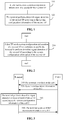
- the method for the signal detection in the another embodiment of the disclosure will be described below in detail in combination with FIG. 4 , in which the first TP is a cell 1 on a carrier 1 and the second TP is a cell 2 on a carrier 2 taken as example.
- FIG. 4 is a schematic flowchart of a method for signal detection according to another embodiment of the disclosure. The method illustrated in FIG. 4 includes the following operations.
- a terminal is accessed to a cell 1 on a carrier 1.
- the terminal may take the cell 1 as a serving cell and performs uplink and downlink data transmission through the cell 1.
- the terminal receives a signaling of the cell 1.
- the signaling carries system configuration information of a carrier 2.
- the system configuration information of the carrier 2 includes: system bandwidth information of the carrier 2, sub-frame offset information of the carrier 2 relative to the carrier 1, CP length information of the carrier 2, configuration information on uplink and downlink time slots of the carrier 2, and CSI-RS configuration information of the carrier 2.
- the terminal performs synchronization signal detection of the carrier 2 according to the system configuration information of the carrier 2 to obtain a synchronization reference of the carrier 2.
- the operation 430 includes the following actions.
- the terminal determines a sub-frame offset of the carrier 2 relative to the carrier 1 according to the sub-frame offset information of the carrier 2 relative to the carrier 1.
- the terminal determines a time-frequency resource estimated position for the synchronization signal on the carrier 2 according to the sub-frame offset and a time-frequency resource position, promised in advance, of the synchronization signal.
- the terminal may perform offset on the time-frequency resource position of the synchronization signal according to the time offset corresponding to the sub-frame offset and determines the offset time-frequency resource position as the time-frequency resource estimated position for the synchronization signal of the carrier 2.
- the time-frequency resource position may be a time-frequency resource position of the synchronization signal that is determined based on downlink timing of the carrier 1.
- the time-frequency resource position, promised in advance, of the synchronization signal may be on a fixed bandwidth for an Mth symbol of an Nth sub-frame, wherein N and M both are a fixed value.
- the terminal performs the synchronization signal detection of the carrier 2 within a time range of a sub-frame length nearby the time-frequency resource estimated position for the synchronization signal of the carrier 2.
- the terminal determines a synchronization reference of the carrier 2 according to the detected synchronization signal.
- the synchronization reference may be at least one of a time synchronization reference or a frequency synchronization reference of the carrier 2.
- the terminal detects a CSI-RS signal and performs RMM measurement according to the synchronization reference of the carrier 2 and the CSI-RS configuration information of the carrier 2.
- the operation 440 includes the following actions.
- the terminal may determine the number of sub-carriers on a bandwidth of the carrier 2 according to the bandwidth configuration information and the sub-carrier spacing information of the carrier 2, and thus determines a CSI-RS sequence length.
- the terminal generates a CSI-RS sequence based on the CSI-RS sequence length and CSI-RS sequence configuration information.
- the terminal determines a time-frequency resource occupied by the CSI-RS signal according to the CP length information of the carrier 2, the configuration information on uplink and downlink time slots of the carrier 2 and the CSI-RS time-frequency resource configuration information.
- the terminal performs the detection of the CSI-RS signal and determines an RRM measurement result based on the synchronization reference of the carrier 2, the time-frequency resource occupied by the CSI-RS and the CSI-RS sequence generated by the terminal.
- the terminal determines whether to perform cell access on the carrier 2 according to the RRM measurement result.
- the terminal may send an RRM measurement result to the cell 1, so that the cell 1 determines whether the terminal performs the cell access on the carrier 2.
- FIG. 5 and FIG. 7 can implement each operation in FIG. 1
- the device illustrated in FIG. 6 and FIG. 8 can implement each operation in FIG. 2 , which will not be elaborated herein to avoid repetitions.
- FIG. 5 is a schematic block diagram of a device for signal detection according to an embodiment of the disclosure.
- the device illustrated in FIG. 5 may be a terminal.
- the device 500 illustrated in FIG. 5 includes a receiving module 510 and a processing module 520.
- the receiving module 510 is configured to receive from a first TP system configuration information of a second TP.
- the processing module 520 is configured to perform downlink signal detection of the second TP according to the system configuration information, received by the receiving module, of the second TP.
- the terminal can acquire the system configuration information of the second TP from the first TP, thereby reducing the complexity of the terminal to perform the signal detection of the second TP.
- the system configuration information may include at least one of the following: working frequency point information of the second TP, system bandwidth information of the second TP, time synchronization information of the second TP relative to the first TP, sub-carrier spacing information of the second TP, prefix information of a signal of the second TP, configuration information on structure of sub-frames of the second TP, configuration information on uplink and downlink time slots of the second TP, configuration information on a synchronization signal of the second TP, configuration information on a reference signal of the second TP, ID information of the second TP or antenna configuration information of the second TP.
- the time synchronization information of the second TP relative to the first TP may include at least one of indication information for indicating whether the second TP is synchronous with the first TP, or a time synchronization offset of the second TP relative to the first TP.
- the time synchronization information may include the indication information for indicating whether the second TP is synchronous with the first TP.
- the processing module may specifically be configured to: perform, responsive to indicating that the second TP is synchronous with the first TP, the downlink signal detection of the second TP according to downlink timing of the first TP; or, determine a detection window for the synchronization signal of the second TP according to the downlink timing of the first TP, perform synchronization signal detection of the second TP in the detection window to obtain synchronization reference of the second TP and perform the downlink signal detection of the second TP according to the synchronization reference of the second TP.
- the time synchronization information may include the indication information for indicating whether the second TP is synchronous with the first TP.
- the processing module may further be configured to: detect, responsive to indicating that the second TP is asynchronous with the first TP, the synchronization signal of the second TP to obtain the synchronization reference of the second TP and perform the downlink signal detection of the second TP according to the synchronization reference of the second TP.
- the time synchronization offset of the second TP relative to the first TP may include at least one of: a radio frame offset of the second TP relative to the first TP, a sub-frame offset of the second TP relative to the first TP, a TTI offset of the second TP relative to the first TP, or a transmission symbol offset of the second TP relative to the first TP.
- the time synchronization information may include the time synchronization offset of the second TP relative to the first TP.
- the processing module may specifically be configured to: determine a detection window for the synchronization signal of the second TP according to the time synchronization offset and a time-frequency resource predetermined for the synchronization signal of the second TP, perform synchronization signal detection of the second TP in the detection window to obtain synchronization reference of the second TP, and perform the downlink signal detection of the second TP according to the synchronization reference of the second TP.
- the configuration information on the synchronization signal of the second TP may include at least one of resource position information of the synchronization signal or sequence information carried in the synchronization signal.
- the processing module may specifically be configured to: determine at least one of time-frequency resource position or sequence information for the synchronization signal of the second TP according to at least one of the resource position information of the synchronization signal or the sequence information carried in the synchronization signal, detect the synchronization signal of the second TP according to at least one of the time-frequency resource position or sequence information to obtain synchronization reference of the second TP, and perform the downlink signal detection of the second TP according the synchronization reference of the second TP.
- the configuration information on the reference signal of the second TP may include at least one of: configuration information on time-frequency resources of the reference signal, sequence information of the reference signal, configuration information on transmitting power of the reference signal or port configuration information of the reference signal.
- the system configuration information of the second TP may include the configuration information on the reference signal of the second TP.
- the processing module may specifically be configured to: determine a configuration for the reference signal of the second TP according to the configuration information on the reference signal of the second TP and perform downlink RRM measurement of the second TP according to the configuration for the reference signal of the second TP.
- the device may further include: a first generation module, configured to generate an RRM measurement result; a first sending module, configured to send the RRM measurement result to the first TP; or, a determination module, configured to determine whether the second TP is detected according to the RRM measurement result.
- the system configuration information may include the working frequency point information of the second TP.
- the processing module may specifically be configured to determine a working frequency point of the second TP according to the working frequency point information of the second TP and perform the downlink signal detection within a bandwidth where the working frequency point is located.
- the prefix information for the signal of the second TP may include at least one of prefix type information or prefix length information.
- the processing module may specifically be configured to: determine at least one of a prefix type or a prefix length of the downlink signal of the second TP according to the prefix information of the signal of the second TP and perform the downlink signal detection of the second TP.
- the downlink signal of the second TP may be a downlink signal carrying a prefix corresponding to at least one of the prefix type or the prefix length.
- the system configuration information of the second TP may include the sub-carrier spacing information of the second TP.
- the processing module may specifically be configured to: determine the number of sub-carriers within a target bandwidth of the second TP according to the sub-carrier spacing information and perform the downlink signal detection of the second TP according to the number of sub-carriers within the target bandwidth.
- the configuration information on structure of sub-frames of the second TP may include at least one of the number of OFDM symbols in a sub-frame, the number of GPs in the sub-frame, positions of the GPs in the sub-frame, or the number of different types of OFDM symbols in the sub-frame.
- the system configuration information may include the configuration information on structure of sub-frames of the second TP
- the processing module may be configured to determine a sub-frame structure of the second TP according to the configuration information on structure of sub-frames of the second TP and perform the downlink signal detection of the second TP according to the sub-frame structure.
- the system configuration information may include the system bandwidth information of the second TP
- the processing module may be configured to determine a system bandwidth of the second TP according to the system bandwidth information of the second TP, and perform the downlink signal detection of the second TP within the system bandwidth of the second TP.
- the system configuration information may include the configuration information on the uplink and downlink time slots of the second TP
- the processing module may be configured to determine a time-frequency resource position of a downlink signal transmitted in the second TP according to the configuration information on uplink and downlink time slots of the second TP and perform the downlink signal detection of the second TP on the time-frequency resource position.
- the system configuration information may include the antenna configuration information of the second TP.
- the processor may be configured to determine an antenna port used by the second TP for transmitting the downlink signal according to the antenna configuration information, and perform the downlink signal detection of the second TP according to the antenna port.
- the system configuration information may include an ID of the second TP.
- the processor may be configured to determine at least one of a transmission format or a sequence for the downlink signal of the second TP according to the ID of the second TP, and perform the downlink signal detection of the second TP according to at least one of the transmission format or the sequence for the downlink signal.
- the first TP may be a carrier for transmitting LTE data
- the second TP may be a carrier for transmitting 5G NR data.
- the device further may include a second generation module and a second sending module.
- the second generation module may be configured to generate a measurement result or a detection result for the downlink signal of the second TP.
- the second sending module may be configured to send the measurement result or the detection result to the first TP.
- the device may further include a third sending module.
- the third sending module may be configured to send an uplink signal to the second TP according to the system configuration information of the second TP.
- FIG. 6 is a schematic block diagram of a device for signal detection according to another embodiment of the disclosure.
- the device 600 for the signal detection illustrated in FIG. 6 includes an acquiring module 610 and a sending module 620.
- the acquiring module 610 is configured to acquire system configuration information of the second TP.
- the sending module 620 is configured to send the system configuration information of the second TP to a terminal, to enable the terminal to perform downlink signal detection of the second TP according to the system configuration information of the second TP.
- the terminal can acquire the system configuration information of the second TP from the first TP, thereby reducing the complexity of the terminal to perform the signal detection of the second TP.
- the system configuration information may include at least one of the following: working frequency point information of the second TP, system bandwidth information of the second TP, time synchronization information of the second TP relative to the first TP, sub-carrier spacing information of the second TP, prefix information of a signal of the second TP, configuration information on structure of sub-frames of the second TP, configuration information on uplink and downlink time slots of the second TP, configuration information on a synchronization signal of the second TP, configuration information on a reference signal of the second TP, ID information of the second TP or antenna configuration information of the second TP.
- the first TP may be a carrier for transmitting LTE data
- the second TP may be a carrier for transmitting 5G NR data.
- the device may further include a receiving module.
- the receiving module may be configured to receive a measurement result or a detection result sent by the terminal for the downlink signal of the second TP.
- FIG. 7 is a schematic block diagram of a device for signal detection according to another embodiment of the disclosure.
- the device 700 for the signal detection illustrated in FIG. 7 includes a memory 710, a processor 720, an input/output interface 730, a communication interface 740 and a bus system 750.
- the memory 710, the processor 720, the input/output interface 730 and the communication interface 740 are connected via the bus system 750.
- the memory 710 may be configured to store an instruction.
- the processor 720 may be configured to execute the instruction stored in the memory 720 to control the input/output interface 730 to receive input data and information, output data such as an operation result and control the communication interface 740 to transmit a signal.
- the receiving module 740 may be configured to receive from a first TP system configuration information of a second TP.
- the processor 720 may be configured to perform downlink signal detection of the second TP according to the system configuration information of the second TP.
- the processor 720 may adopt a universal Central Processing Unit (CPU), a microprocessor, an Application Specific Integrated Circuit (ASIC) or one or more integrated circuit, and may be configured to execute a related program to implement the technical solutions provided in the embodiments of the disclosure.
- CPU Central Processing Unit
- ASIC Application Specific Integrated Circuit
- the communication interface 740 employs, for example but not limited to, a transceiver device such as a transceiver to implement communication between the device 700 for signal detection and other devices or communication networks.
- the memory 710 may include a Read-Only Memory (ROM) and a Random-Access Memory (RAM) and provides instructions and data to the processor 720.
- a part of the processor 720 may further include a nonvolatile RAM.
- the processor 720 may further store information of a device type.
- the bus system 750 may include a data bus, and may further include a power bus, a control bus, a state signal bus and the like. However, for clear description, various buses in the figure are marked as the bus system 750.
- each operation of the method may be completed by an integrated logic circuit of hardware in the processor 720 or an instruction in a software form.
- the method for signal detection disclosed in combination with the embodiments of the disclosure may be directly embodied to be executed and completed by a hardware processor or executed and completed by a combination of hardware and software modules in the processor.
- the software module may be located in a mature storage medium in this field such as a RAM, a flash memory, a ROM, a Programmable ROM (PROM) or Electrically Erasable PROM (EEPROM) and a register.
- the storage medium is located in the memory 710.
- the processor 720 reads information in the memory 710 and completes the operations of the method in combination with hardware. No more detailed descriptions will be made herein to avoid repetitions.
- the terminal can acquire the system configuration information of the second TP from the first TP, thereby reducing the complexity of the terminal to perform the signal detection of the second TP.
- the system configuration information includes at least one of the following: working frequency point information of the second TP, system bandwidth information of the second TP, time synchronization information of the second TP relative to the first TP, sub-carrier spacing information of the second TP, prefix information of a signal of the second TP, configuration information on structure of sub-frames of the second TP, configuration information on uplink and downlink time slots of the second TP, configuration information on a synchronization signal of the second TP, configuration information on a reference signal of the second TP, ID information of the second TP or antenna configuration information of the second TP.
- the time synchronization information of the second TP relative to the first TP includes at least one of indication information for indicating whether the second TP is synchronous with the first TP, or a time synchronization offset of the second TP relative to the first TP.
- the time synchronization information includes the indication information for indicating whether the second TP is synchronous with the first TP or not
- the processor may specifically be configured to: perform, when the second TP is synchronous with the first TP, the downlink signal detection of the second TP according to downlink timing of the first TP; or, determine a detection window for the synchronization signal of the second TP according to the downlink timing of the first TP, perform synchronization signal detection of the second TP in the detection window to obtain synchronization reference of the second TP and perform the downlink signal detection of the second TP according to the synchronization reference of the second TP.
- the time synchronization information includes the indication information for indicating whether the second TP is synchronous with the first TP
- the processing module may further be configured to detect, when the second TP is asynchronous with the first TP, the synchronization signal of the second TP to obtain synchronization reference of the second TP and perform the downlink signal detection of the second TP according to the synchronization reference of the second TP.
- the time synchronization offset of the second TP relative to the first TP may include at least one of a radio frame offset of the second TP relative to the first TP, a sub-frame offset of the second TP relative to the first TP, a TTI offset of the second TP relative to the first TP, or a transmission symbol offset of the second TP relative to the first TP.
- the time synchronization information includes the time synchronization offset of the second TP relative to the first TP.
- the processor may specifically be configured to determine a detection window for the synchronization signal of the second TP according to the time synchronization offset and a time-frequency resource predetermined for the synchronization signal of the second TP, perform synchronization signal detection of the second TP in the detection window to obtain synchronization reference of the second TP and perform the downlink signal detection of the second TP according to the synchronization reference of the second TP.
- the configuration information on the synchronization signal of the second TP includes at least one of resource position information of the synchronization signal or sequence information carried in the synchronization signal.
- the processor may specifically be configured to determine at least one of time-frequency resource position or sequence information for the synchronization signal of the second TP according to at least one of the resource position information of the synchronization signal or the sequence information carried in the synchronization signal, detect the synchronization signal of the second TP according to at least one of the time-frequency resource position or sequence information to obtain the synchronization reference of the second TP and perform the downlink signal detection of the second TP according the synchronization reference of the second TP.
- the configuration information on the reference signal of the second TP includes at least one of the following: configuration information on time-frequency resources of the reference signal, sequence information of the reference signal, configuration information on transmitting power of the reference signal or port configuration information of the reference signal.
- the system configuration information of the second TP includes the configuration information on the reference signal of the second TP.
- the processor may specifically be configured to determine a configuration for the reference signal of the second TP according to the configuration information on the reference signal of the second TP and perform downlink RRM measurement of the second TP according to the configuration for the reference signal of the second TP.
- the device further may include: a first generation module, configured to generate an RRM measurement result; a first sending module, configured to send the RRM measurement result to the first TP; or, a determination module, configured to determine whether the second TP is detected according to the RRM measurement result.
- the system configuration information includes the working frequency point information of the second TP.
- the processor may specifically be specifically configured to determine a working frequency point of the second TP according to the working frequency point information of the second TP and perform the downlink signal detection within a bandwidth where the working frequency point is located.
- the prefix information for the signal of the second TP includes at least one of prefix type information or prefix length information.
- the processor may specifically be configured to determine at least one of a prefix type or a prefix length of the downlink signal of the second TP according to the prefix information of the signal of the second TP, and perform the downlink signal detection of the second TP.
- the downlink signal of the second TP may be a downlink signal carrying a prefix corresponding to at least one of the prefix type or the prefix length.
- the system configuration information of the second TP includes the sub-carrier spacing information of the second TP.
- the processor may specifically be configured to determine the number of sub-carriers within a target bandwidth of the second TP according to the sub-carrier spacing information and perform the downlink signal detection of the second TP according to the number of sub-carriers within the target bandwidth.
- the configuration information on structure of sub-frames of the second TP includes at least one of the number of OFDM symbols in a sub-frame, the number of GPs in the sub-frame, positions of the GPs in the sub-frame, or the number of different types of OFDM symbols in the sub-frame.
- the system configuration information includes the configuration information on structure of sub-frames of the second TP.
- the processor may be configured to determine a sub-frame structure of the second TP according to the configuration information on structure of sub-frames of the second TP and perform the downlink signal detection of the second TP according to the sub-frame structure.
- the system configuration information includes the system bandwidth information of the second TP.
- the processor may be configured to determine a system bandwidth of the second TP according to the system bandwidth information of the second TP and perform the downlink signal detection of the second TP within the system bandwidth of the second TP.
- the system configuration information includes the configuration information on uplink and downlink time slots of the second TP.
- the processor may be configured to: determine a time-frequency resource position of a downlink signal transmitted in the second TP according to the configuration information on uplink and downlink time slots of the second TP and perform the downlink signal detection of the second TP on the time-frequency resource position.
- the system configuration information includes the antenna configuration information of the second TP.
- the processor may be configured to determine an antenna port used by the second TP for transmitting the downlink signal according to the antenna configuration information and perform the downlink signal detection of the second TP according to the antenna port.
- the system configuration information includes an ID of the second TP.
- the processor may be configured to determine at least one of a transmission format or a sequence for the downlink signal of the second TP according to the ID of the second TP and perform the downlink signal detection of the second TP according to at least one of the transmission format or the sequence for the downlink signal.
- the first TP may be a carrier for transmitting LTE data
- the second TP may be a carrier for transmitting 5G NR data.
- the processor may further be configured to generate a measurement result or a detection result for the downlink signal of the second TP.
- the communication interface may be configured to send the measurement result or the detection result to the first TP.
- the communication interface may be configured to send an uplink signal to the second TP according to the system configuration information of the second TP.
- FIG. 8 is a schematic block diagram of a device for signal detection according to another embodiment of the disclosure.
- the device 800 for the signal detection illustrated in FIG. 8 may be a first TP.
- the device 800 includes a memory 810, a processor 820, an input/output interface 830, a communication interface 840 and a bus system 850.
- the memory 810, the processor 820, the input/output interface 830 and the communication interface 840 are connected via the bus system 850.
- the memory 810 may be configured to store an instruction.
- the processor 820 may be configured to execute the instruction stored in the memory 820 to control the input/output interface 830 to receive input data and information, output data such as an operation result and control the communication interface 840 to transmit a signal.
- the processor 820 may be configured to acquire system configuration information of a second TP.
- the communication interface 840 may be configured to send system configuration information of the second TP to a terminal, to enable the terminal to perform downlink signal detection of the second TP according to the system configuration information of the second TP.
- the processor 820 may adopt a universal Central Processing Unit (CPU), a microprocessor, an Application Specific Integrated Circuit (ASIC) or one or more integrated circuit, and may be configured to execute a related program to implement the technical solutions provided in the embodiments of the disclosure.
- CPU Central Processing Unit
- ASIC Application Specific Integrated Circuit
- the communication interface 840 employs, for example but not limited to, a transceiver device such as a transceiver to implement communication between the device 800 for signal detection and other devices or communication networks.
- the memory 810 may include a Read-Only Memory (ROM) and a Random-Access Memory (RAM) and provides instructions and data to the processor 820.
- a part of the processor 820 may further include a nonvolatile RAM.
- the processor 820 may further store information of a device type.
- the bus system 850 may include a data bus, and may further include a power bus, a control bus, a state signal bus and the like. However, for clear description, various buses in the figure are marked as the bus system 850.
- each operation of the method may be completed by an integrated logic circuit of hardware in the processor 820 or an instruction in a software form.
- the method for signal detection disclosed in combination with the embodiments of the disclosure may be directly embodied to be executed and completed by a hardware processor or executed and completed by a combination of hardware and software modules in the processor.
- the software module may be located in a mature storage medium in this field such as a RAM, a flash memory, a ROM, a Programmable ROM (PROM) or Electrically Erasable PROM (EEPROM) and a register.
- the storage medium is located in the memory 810.
- the processor 820 reads information in the memory 810 and completes the operations of the method in combination with hardware. No more detailed descriptions will be made herein to avoid repetitions.
- the terminal can acquire the system configuration information of the second TP from the first TP, thereby reducing the complexity of the terminal to perform the signal detection of the second TP.
- the system configuration information includes at least one of the following: working frequency point information of the second TP, system bandwidth information of the second TP, time synchronization information of the second TP relative to the first TP, sub-carrier spacing information of the second TP, prefix information of a signal of the second TP, configuration information on structure of sub-frames of the second TP, configuration information on uplink and downlink time slots of the second TP, configuration information on a synchronization signal of the second TP, configuration information on a reference signal of the second TP, ID information of the second TP or antenna configuration information of the second TP.
- the first TP may be a carrier for transmitting LTE data
- the second TP may be a carrier for transmitting 5G NR data.
- the communication interface may be configured to receive a measurement result or a detection result for the downlink signal of the second TP from the terminal.
- B corresponding to A represents that B is associated with A and B may be determined according to A. It is also to be understood that determining B according to A does not mean that B is determined only according to A and B may also be determined according to A and/or other information.
- a sequence number of each process does not mean an execution sequence and the execution sequence of each process should be determined by its function and an internal logic and should not form any limit to an implementation process of the embodiments of the disclosure.
- the disclosed system, device and method may be implemented in another manner.
- the device embodiment described above is only schematic, and for example, division of the units is only logic function division, and other division manners may be adopted during practical implementation.
- multiple units or components may be combined or integrated into another system, or some characteristics may be neglected or not executed.
- coupling or direct coupling or communication connection between each displayed or discussed component may be indirect coupling or communication connection, implemented through some interfaces, of the device or the units, and may be electrical and mechanical or adopt other forms.
- the units described as separate parts may or may not be physically separated, and parts displayed as units may or may not be physical units, and namely may be located in the same place, or may also be distributed to multiple network units. Part or all of the units may be selected to achieve the purpose of the solutions of the embodiments according to a practical requirement.
- each function unit in each embodiment of the disclosure may be integrated into a processing unit, each unit may also exist independently, and two or more than two units may also be integrated into a unit.
- the function may also be stored in a computer-readable storage medium.
- the technical solutions of the disclosure substantially or parts making contributions to the conventional art or part of the technical solutions may be embodied in form of software product, and the computer software product is stored in a storage medium, including a plurality of instructions configured to enable a computer device (which may be a personal computer, a server, a network device or the like) to execute all or part of the operations of the method in each embodiment of the disclosure.
- the abovementioned storage medium includes: various media capable of storing program codes such as a U disk, a mobile hard disk, a ROM, a RAM, a magnetic disk or an optical disk.
Landscapes
- Engineering & Computer Science (AREA)
- Signal Processing (AREA)
- Computer Networks & Wireless Communication (AREA)
- Computer Security & Cryptography (AREA)
- Databases & Information Systems (AREA)
- Mobile Radio Communication Systems (AREA)
- Radar Systems Or Details Thereof (AREA)
- Small-Scale Networks (AREA)
Claims (14)
- Verfahren zur Signalerfassung, umfassend:Empfangen (110) von Systemkonfigurationsinformationen eines zweiten TPs durch ein Endgerät aus einem ersten Übertragungspunkt, TP, wobei die Systemkonfigurationsinformationen Zeitsynchronisationsinformationen des zweiten TPs umfassen und die Zeitsynchronisationsinformationen des zweiten TPs Anzeigeinformationen zum Anzeigen, ob der zweite TP mit dem ersten TP synchron ist, umfassen; undDurchführen (120) einer Abwärtsstreckensignalerfassung des zweiten TPs gemäß der Abwärtsstreckenzeitsteuerung des ersten TPs durch das Endgerät, wenn die Anzeigeinformationen anzeigen, dass der zweite TP synchron mit dem ersten TP ist;wobei der erste TP und der zweite TP unterschiedliche Zellen sind.
- Verfahren gemäß Anspruch 1, wobei die Systemkonfigurationsinformationen ferner mindestens eine der folgenden Informationen umfassen:
Arbeitsfrequenzpunktinformationen des zweiten TPs, Systembandbreiteninformationen des zweiten TPs, Unterträgerabstandsinformationen des zweiten TPs, Präfixinformationen eines Signals des zweiten TPs, Konfigurationsinformationen über die Struktur von Unterrahmen des zweiten TP, Konfigurationsinformationen über Aufwärts- und Abwärtsstreckenzeitschlitze des zweiten TPs, Konfigurationsinformationen über ein Synchronisationssignal des zweiten TPs, Konfigurationsinformationen über ein Referenzsignal des zweiten TPs, Kennungs-, ID-, Informationen des zweiten TPs oder Antennenkonfigurationsinformationen des zweiten TPs. - Verfahren gemäß Anspruch 1, wobei die Zeitsynchronisationsinformationen des zweiten TPs ferner einen Zeitsynchronisationsversatz des zweiten TPs relativ zum ersten TP umfasst.
- Verfahren gemäß Anspruch 1, ferner umfassend:Erfassen des Synchronisationssignals des zweiten TPs durch das Endgerät, um eine Synchronisationsreferenz des zweiten TPs zu erhalten, wenn die Anzeigeinformationen anzeigen, dass der zweite TP asynchron mit dem ersten TP ist; undDurchführen der Abwärtsstreckensignalerfassung des zweiten TP gemäß der Synchronisationsreferenz des zweiten TP durch das Endgerät.
- Verfahren gemäß Anspruch 2, wobei die Konfigurationsinformationen über das Synchronisationssignal des zweiten TPs mindestens eines von Ressourcenpositionsinformationen des Synchronisationssignals oder im Synchronisationssignal enthaltenen Sequenzinformationen umfasst.
- Verfahren gemäß Anspruch 5, wobei die Systemkonfigurationsinformationen des zweiten TPs die Konfigurationsinformationen über das Synchronisationssignal des zweiten TPs umfassen und das Verfahren ferner umfasst:Bestimmen mindestens eines von Zeit-Frequenz-Ressourcenposition oder Sequenzinformationen über das Synchronisationssignal des zweiten TPs gemäß mindestens eines von Ressourcenpositionsinformationen des Synchronisationssignals oder der im Synchronisationssignal enthaltenen Sequenzinformationen durch das Endgerät;Erkennen des Synchronisationssignals des zweiten TPs durch das Endgerät gemäß mindestens eines von der Zeit-Frequenz-Ressourcenposition oder den Sequenzinformationen, um eine Synchronisationsreferenz des zweiten TPs zu erhalten; undDurchführen der Abwärtsstreckensignalerfassung des zweiten TP gemäß der Synchronisationsreferenz des zweiten TP durch das Endgerät.
- Verfahren gemäß Anspruch 2, wobei die Konfigurationsinformationen über das Referenzsignal des zweiten TPs mindestens eine der folgenden Informationen umfassen: Konfigurationsinformationen über Zeit-Frequenz-Ressourcen des Referenzsignals, Sequenzinformationen des Referenzsignals, Konfigurationsinformationen über die Übertragungsleistung des Referenzsignals oder Portkonfigurationsinformationen des Referenzsignals.
- Verfahren gemäß Anspruch 2 oder 7, wobei die Systemkonfigurationsinformationen des zweiten TPs die Konfigurationsinformationen über das Referenzsignal des zweiten TPs umfassen und das Verfahren ferner umfasst:Bestimmen einer Konfiguration für das Referenzsignal des zweiten TPs durch das Endgerät gemäß den Konfigurationsinformationen über das Referenzsignal des zweiten TPs; undDurchführen einer Abwärtsstrecken-Funkressourcenverwaltungs-, RRM-, Messung des zweiten TPs durch das Endgerät gemäß der Konfiguration für das Referenzsignal des zweiten TPs, unddas Verfahren ferner umfasst:Erzeugen eines RRM-Messergebnisses durch das Endgerät; undSenden des RRM-Messergebnisses durch das Endgerät an den ersten TP; oder Bestimmen durch das Endgerät, ob der zweite TP gemäß dem RRM-Messergebnis erfasst ist.
- Verfahren gemäß Anspruch 2, wobei die Systemkonfigurationsinformationen des zweiten TPs die Unterträgerabstandsinformationen des zweiten TPs umfasst und das Verfahren ferner umfasst:Bestimmen einer Anzahl von Unterträgern innerhalb einer Zielbandbreite des zweiten TPs durch das Endgerät gemäß den Unterträgerabstandsinformationen; undDurchführen der Abwärtsstreckensignalerfassung des zweiten TPs durch das Endgerät gemäß der Anzahl der Unterträger innerhalb der Zielbandbreite.
- Verfahren gemäß Anspruch 2, wobei die Konfigurationsinformationen über die Struktur von Unterrahmen des zweiten TPs mindestens eines umfasst von:einer Anzahl von Orthogonal Frequency Division Multiplexing-, OFDM-, Symbolen in einem Unterrahmen, einer Anzahl von Schutzperioden, GPs, in dem Unterrahmen, Positionen der GPs in dem Unterrahmen, oder einer Anzahl von verschiedenen Typen von OFDM-Symbolen in dem Unterrahmen;wobei die Systemkonfigurationsinformationen die Konfigurationsinformationen über die Struktur der Unterrahmen des zweiten TPs umfassen und das Verfahren ferner umfasst:Bestimmen einer Unterrahmenstruktur des zweiten TPs durch das Endgerät gemäß den Konfigurationsinformationen über die Struktur von Unterrahmen des zweiten TPs; undDurchführen der Abwärtsstreckensignalerfassung des zweiten TPs gemäß der Unterrahmenstruktur durch das Endgerät.
- Verfahren gemäß einem der Ansprüche 1-10, ferner umfassend:Erzeugen eines Messergebnisses oder eines Erfassungsergebnisses für das Abwärtsstreckensignal des zweiten TPs durch das Endgerät; undSenden des Messergebnisses oder des Erfassungsergebnisses durch das Endgerät an den ersten TP.
- Verfahren zur Signalerfassung, umfassend:
Senden (210) von Systemkonfigurationsinformationen eines zweiten TPs an ein Endgerät durch einen ersten Übertragungspunkt, TP, wobei die Systemkonfigurationsinformationen Zeitsynchronisationsinformationen des zweiten TPs umfassen und die Zeitsynchronisationsinformationen des zweiten TPs Anzeigeinformationen zum Anzeigen umfassen, ob der zweite TP mit dem ersten TP synchron ist, um das Endgerät in die Lage zu versetzen, eine Abwärtsstreckensignalerfassung des zweiten TPs gemäß der Abwärtsstreckenzeitsteuerung des ersten TPs durchzuführen, wenn die Anzeigeinformationen anzeigen, dass der zweite TP mit dem ersten TP synchron ist, wobei der erste TP und der zweite TP unterschiedliche Zellen sind. - Verfahren gemäß Anspruch 12, wobei die Systemkonfigurationsinformationen ferner mindestens eine der folgenden Informationen umfassen:
Arbeitsfrequenzpunktinformationen des zweiten TPs, Systembandbreiteninformationen des zweiten TPs, Unterträgerabstandsinformationen des zweiten TPs, Präfixinformationen eines Signals des zweiten TPs, Konfigurationsinformationen über die Struktur von Unterrahmen des zweiten TPs, Konfigurationsinformationen über Aufwärts- und Abwärtsstreckenzeitschlitze des zweiten TPs, Konfigurationsinformationen über ein Synchronisationssignal des zweiten TPs, Konfigurationsinformationen über ein Referenzsignal des zweiten TPs, Kennungs-, ID-, Informationen des zweiten TPs oder Antennenkonfigurationsinformationen des zweiten TPs. - Vorrichtung zur Signalerfassung, umfassend:einen Speicher (710); undeinen Prozessor (720), der dazu ausgelegt ist, eine in dem Speicher (710) gespeicherte Anweisung auszuführen, um die Vorrichtung in die Lage zu versetzen, das Verfahren gemäß einem der Ansprüche 1-11 auszuführen.
Priority Applications (3)
| Application Number | Priority Date | Filing Date | Title |
|---|---|---|---|
| PT211502885T PT3823371T (pt) | 2016-07-01 | 2016-07-01 | Método e dispositivo para deteção de sinal |
| EP21150288.5A EP3823371B1 (de) | 2016-07-01 | 2016-07-01 | Verfahren und vorrichtung zur signalerfassung |
| EP24214085.3A EP4489349A3 (de) | 2016-07-01 | 2016-07-01 | Verfahren und vorrichtung zur signaldetektion |
Applications Claiming Priority (1)
| Application Number | Priority Date | Filing Date | Title |
|---|---|---|---|
| PCT/CN2016/088244 WO2018000440A1 (zh) | 2016-07-01 | 2016-07-01 | 信号检测的方法和装置 |
Related Child Applications (3)
| Application Number | Title | Priority Date | Filing Date |
|---|---|---|---|
| EP21150288.5A Division-Into EP3823371B1 (de) | 2016-07-01 | 2016-07-01 | Verfahren und vorrichtung zur signalerfassung |
| EP21150288.5A Division EP3823371B1 (de) | 2016-07-01 | 2016-07-01 | Verfahren und vorrichtung zur signalerfassung |
| EP24214085.3A Division EP4489349A3 (de) | 2016-07-01 | 2016-07-01 | Verfahren und vorrichtung zur signaldetektion |
Publications (3)
| Publication Number | Publication Date |
|---|---|
| EP3474508A1 EP3474508A1 (de) | 2019-04-24 |
| EP3474508A4 EP3474508A4 (de) | 2019-06-26 |
| EP3474508B1 true EP3474508B1 (de) | 2021-02-24 |
Family
ID=60785091
Family Applications (3)
| Application Number | Title | Priority Date | Filing Date |
|---|---|---|---|
| EP16906839.2A Active EP3474508B1 (de) | 2016-07-01 | 2016-07-01 | Verfahren und vorrichtung zur signalerfassung |
| EP24214085.3A Pending EP4489349A3 (de) | 2016-07-01 | 2016-07-01 | Verfahren und vorrichtung zur signaldetektion |
| EP21150288.5A Active EP3823371B1 (de) | 2016-07-01 | 2016-07-01 | Verfahren und vorrichtung zur signalerfassung |
Family Applications After (2)
| Application Number | Title | Priority Date | Filing Date |
|---|---|---|---|
| EP24214085.3A Pending EP4489349A3 (de) | 2016-07-01 | 2016-07-01 | Verfahren und vorrichtung zur signaldetektion |
| EP21150288.5A Active EP3823371B1 (de) | 2016-07-01 | 2016-07-01 | Verfahren und vorrichtung zur signalerfassung |
Country Status (20)
| Country | Link |
|---|---|
| US (4) | US10813065B2 (de) |
| EP (3) | EP3474508B1 (de) |
| JP (1) | JP6847986B2 (de) |
| KR (1) | KR102614082B1 (de) |
| CN (2) | CN112601238B (de) |
| AU (1) | AU2016413381B2 (de) |
| BR (1) | BR112018077445B1 (de) |
| CA (1) | CA3029562C (de) |
| ES (2) | ES3010494T3 (de) |
| FI (1) | FI3823371T3 (de) |
| IL (1) | IL264019A (de) |
| MX (1) | MX392557B (de) |
| MY (1) | MY205964A (de) |
| PH (1) | PH12019500005A1 (de) |
| PT (1) | PT3823371T (de) |
| RU (1) | RU2726172C1 (de) |
| SG (1) | SG11201811824RA (de) |
| TW (1) | TWI784958B (de) |
| WO (1) | WO2018000440A1 (de) |
| ZA (1) | ZA201900665B (de) |
Families Citing this family (10)
| Publication number | Priority date | Publication date | Assignee | Title |
|---|---|---|---|---|
| JP6847986B2 (ja) * | 2016-07-01 | 2021-03-24 | オッポ広東移動通信有限公司Guangdong Oppo Mobile Telecommunications Corp., Ltd. | 信号検出方法及び装置 |
| KR102178412B1 (ko) * | 2016-07-15 | 2020-11-16 | 주식회사 케이티 | 새로운 무선 액세스 망에서 단말을 위한 동기화 신호 및 시스템 정보를 송수신하는 방법 및 장치 |
| CN108282880B (zh) * | 2017-01-06 | 2019-11-08 | 电信科学技术研究院 | 一种确定下行数据信道的起始位置的方法及装置 |
| CN108282855B (zh) * | 2017-01-06 | 2024-06-18 | 华为技术有限公司 | 上行功率控制方法及终端 |
| WO2018170656A1 (zh) * | 2017-03-20 | 2018-09-27 | Oppo广东移动通信有限公司 | 传输数据的方法、终端设备和网络设备 |
| CN108809587B (zh) | 2017-05-05 | 2021-06-08 | 华为技术有限公司 | 确定参考信号序列的方法、终端设备、网络设备 |
| CN110113122B (zh) * | 2018-02-01 | 2021-06-22 | 华为技术有限公司 | 一种定时的方法及装置 |
| CN111357251A (zh) | 2018-09-18 | 2020-06-30 | Oppo广东移动通信有限公司 | 一种信号传输的方法、装置及计算机存储介质 |
| US12267195B2 (en) * | 2018-10-02 | 2025-04-01 | Huawei Technologies Co., Ltd. | System and method for reducing power consumption using power saving reference signals |
| US11689267B2 (en) * | 2019-05-03 | 2023-06-27 | Mediatek Inc. | Aperiodic CSI triggering in scenarios with multiple PDCCHs |
Family Cites Families (48)
| Publication number | Priority date | Publication date | Assignee | Title |
|---|---|---|---|---|
| KR101012857B1 (ko) * | 2006-10-18 | 2011-02-08 | 삼성전자주식회사 | 제1차 동기채널과 제2차 동기채널이 tdm으로 구성된ofdm 셀룰라 시스템에서의 셀 탐색 방법 |
| CN101682881B (zh) * | 2007-04-11 | 2013-12-11 | 艾利森电话股份有限公司 | 用于相邻小区测量的关于参考信号结构的信息 |
| US9264907B2 (en) | 2007-07-10 | 2016-02-16 | Qualcomm Incorporated | Method and apparatus for interference management between networks sharing a frequency spectrum |
| US9037750B2 (en) | 2007-07-10 | 2015-05-19 | Qualcomm Incorporated | Methods and apparatus for data exchange in peer to peer communications |
| CN102217209B (zh) | 2009-01-13 | 2015-06-03 | 华为技术有限公司 | 信息发送和获取的方法、装置和系统 |
| CN102281555B (zh) | 2010-06-13 | 2016-03-09 | 华为技术有限公司 | 小区检测的方法、装置及系统 |
| US9106380B2 (en) | 2010-06-21 | 2015-08-11 | Telefonaktiebolaget L M Ericsson (Publ) | Method and arrangement for signaling of parameters in a wireless network |
| US9078207B2 (en) | 2010-11-18 | 2015-07-07 | Nokia Technologies Oy | Method and apparatus for timing advance estimation |
| CN102291737B (zh) * | 2011-08-09 | 2014-01-29 | 电信科学技术研究院 | 一种主传输点的确定方法和设备 |
| CN102932907B (zh) * | 2011-08-11 | 2016-03-09 | 华为技术有限公司 | 一种获取同步的处理方法以及设备 |
| US20130229953A1 (en) | 2011-08-16 | 2013-09-05 | Samsung Electronics Co., Ltd. | Apparatus and method for indicating synchronization signals in a wireless network |
| US8842637B2 (en) | 2011-12-04 | 2014-09-23 | Ofinno Technologies, Llc | Carrier information transmission to wireless devices |
| US8879496B2 (en) * | 2011-12-19 | 2014-11-04 | Ofinno Technologies, Llc | Beamforming codeword exchange between base stations |
| CN102547968B (zh) * | 2012-01-16 | 2014-09-10 | 电信科学技术研究院 | 一种协作多点传输下行同步方法及装置 |
| CN103220249B (zh) | 2012-01-19 | 2018-04-06 | 中兴通讯股份有限公司 | 一种信息的传输、配置方法及装置 |
| US9955442B2 (en) | 2012-03-20 | 2018-04-24 | Qualcomm Incorporated | Synchronization channel design for new carrier type |
| US20130258956A1 (en) * | 2012-04-01 | 2013-10-03 | Esmael Hejazi Dinan | Random Access Process in a Wireless Device |
| US9232503B2 (en) * | 2012-04-27 | 2016-01-05 | Intel Corporation | Apparatus and method for cell information indication in a wireless network |
| US9357417B2 (en) | 2012-08-17 | 2016-05-31 | Telefonaktiebolaget L M Ericsson | Methods, systems and devices for obtaining system information in a wireless network |
| US9531510B2 (en) | 2012-11-04 | 2016-12-27 | Lg Electronics Inc. | Method for transmitting/receiving synchronizing signal in wireless communication system and device therefor |
| US9276726B2 (en) | 2012-12-11 | 2016-03-01 | Samsung Electronics Co., Ltd. | Transmissions/receptions of uplink acknowledgement signals in wireless networks |
| KR101988506B1 (ko) | 2012-12-14 | 2019-09-30 | 삼성전자 주식회사 | 무선 이동통신 시스템에서 디스커버리 신호를 송/수신하는 방법 및 장치 |
| KR20140080388A (ko) * | 2012-12-20 | 2014-06-30 | 주식회사 팬택 | 셀 확인 정보 송수신 방법 및 그 장치 |
| JP5809660B2 (ja) | 2013-01-09 | 2015-11-11 | 株式会社Nttドコモ | 無線通信システムおよび通信制御方法 |
| US9420512B2 (en) * | 2013-01-17 | 2016-08-16 | Apple Inc. | Handling uplink power limited scenarios |
| CN104170433B (zh) * | 2013-01-24 | 2018-03-09 | 华为技术有限公司 | 一种测量方法、用户设备、基站及无线通信系统 |
| CN104937869B (zh) * | 2013-01-25 | 2018-03-23 | Lg电子株式会社 | 用于在支持载波聚合的无线接入系统中的无线电资源测量的方法及支持其的设备 |
| US9775124B2 (en) | 2013-01-31 | 2017-09-26 | Lg Electronics Inc. | Method and apparatus for performing synchronization in wireless communication system |
| US9338700B2 (en) * | 2013-03-20 | 2016-05-10 | Qualcomm Incorporated | Inter-RAT transitioning utilizing system information messaging |
| EP2941066B1 (de) | 2013-04-07 | 2019-06-12 | Huawei Technologies Co., Ltd. | Verfahren und vorrichtung zur übertragung eines gemeinsamen signals |
| JP6224395B2 (ja) | 2013-09-26 | 2017-11-01 | 株式会社Nttドコモ | 基地局、ユーザ端末及び無線通信方法 |
| EP3043610B1 (de) | 2013-09-27 | 2019-09-04 | Huawei Technologies Co., Ltd. | Kommunikationsverfahren, benutzerausrüstung und basisstation |
| CN104519512B (zh) | 2013-09-30 | 2020-01-10 | 锐迪科(重庆)微电子科技有限公司 | 一种自动邻区关系小区检测方法 |
| CN104703164B (zh) | 2013-12-10 | 2018-11-27 | 电信科学技术研究院 | 一种获取同步参考的方法、发送同步信息的方法及设备 |
| WO2015156573A1 (ko) * | 2014-04-09 | 2015-10-15 | 엘지전자 주식회사 | 무선 통신 시스템에서 신호를 송수신하는 방법 및 이를 위한 장치 |
| CN106416376B (zh) * | 2014-05-08 | 2022-08-30 | 株式会社Ntt都科摩 | 用户终端、基站以及无线通信方法 |
| JP6222351B2 (ja) | 2014-05-09 | 2017-11-01 | 愛知製鋼株式会社 | 磁気検出装置およびその製造方法 |
| US9930515B2 (en) * | 2014-05-15 | 2018-03-27 | Lg Electronics Inc. | Method for detecting discovery signal in wireless communication system, and device for same |
| CN111132184B (zh) | 2014-05-27 | 2023-07-21 | Lg电子株式会社 | 执行针对同步信号块的测量的方法和用户设备 |
| CN105472744B (zh) * | 2014-09-02 | 2020-07-31 | 中兴通讯股份有限公司 | 一种数据传输方法和装置 |
| JP6605024B2 (ja) * | 2014-09-24 | 2019-11-13 | エルジー エレクトロニクス インコーポレイティド | D2d信号の送信方法及びそのための端末 |
| CN120129045A (zh) * | 2014-09-24 | 2025-06-10 | 交互数字专利控股公司 | 用于无授权频段中的lte操作的信道使用指示和同步 |
| JPWO2016199494A1 (ja) * | 2015-06-09 | 2018-03-29 | ソニー株式会社 | 制御装置、基地局、端末装置及び制御方法 |
| EP3554032B1 (de) * | 2015-11-06 | 2021-08-18 | Huawei Technologies Co., Ltd. | Datenübertragungsverfahren, endgerät und basisstation in einem laa-lte-system |
| KR102656885B1 (ko) * | 2015-11-13 | 2024-04-12 | 엘지전자 주식회사 | 무선 통신 시스템에서 v2v 통신을 위한 전력 측정 방법 및 이를 위한 장치 |
| KR101984594B1 (ko) * | 2016-02-04 | 2019-06-03 | 주식회사 케이티 | 차량 통신 제어 방법 및 그 장치 |
| US10716020B2 (en) | 2016-02-23 | 2020-07-14 | Samsung Electronics Co., Ltd. | Method and apparatus for measurement reference signal |
| JP6847986B2 (ja) * | 2016-07-01 | 2021-03-24 | オッポ広東移動通信有限公司Guangdong Oppo Mobile Telecommunications Corp., Ltd. | 信号検出方法及び装置 |
-
2016
- 2016-07-01 JP JP2018568430A patent/JP6847986B2/ja active Active
- 2016-07-01 BR BR112018077445-6A patent/BR112018077445B1/pt active IP Right Grant
- 2016-07-01 CN CN202011458189.0A patent/CN112601238B/zh active Active
- 2016-07-01 ES ES21150288T patent/ES3010494T3/es active Active
- 2016-07-01 EP EP16906839.2A patent/EP3474508B1/de active Active
- 2016-07-01 CA CA3029562A patent/CA3029562C/en active Active
- 2016-07-01 FI FIEP21150288.5T patent/FI3823371T3/fi active
- 2016-07-01 RU RU2019102852A patent/RU2726172C1/ru active
- 2016-07-01 MY MYPI2018003006A patent/MY205964A/en unknown
- 2016-07-01 PT PT211502885T patent/PT3823371T/pt unknown
- 2016-07-01 SG SG11201811824RA patent/SG11201811824RA/en unknown
- 2016-07-01 WO PCT/CN2016/088244 patent/WO2018000440A1/zh not_active Ceased
- 2016-07-01 CN CN201680087189.XA patent/CN109417541B/zh active Active
- 2016-07-01 EP EP24214085.3A patent/EP4489349A3/de active Pending
- 2016-07-01 US US16/309,364 patent/US10813065B2/en active Active
- 2016-07-01 EP EP21150288.5A patent/EP3823371B1/de active Active
- 2016-07-01 ES ES16906839T patent/ES2857742T3/es active Active
- 2016-07-01 AU AU2016413381A patent/AU2016413381B2/en active Active
- 2016-07-01 MX MX2019000067A patent/MX392557B/es unknown
- 2016-07-01 KR KR1020197001918A patent/KR102614082B1/ko active Active
-
2017
- 2017-06-29 TW TW106121730A patent/TWI784958B/zh active
-
2018
- 2018-12-30 IL IL264019A patent/IL264019A/en active IP Right Grant
-
2019
- 2019-01-03 PH PH12019500005A patent/PH12019500005A1/en unknown
- 2019-01-31 ZA ZA201900665A patent/ZA201900665B/en unknown
-
2020
- 2020-09-17 US US17/024,316 patent/US11153836B2/en active Active
-
2021
- 2021-09-27 US US17/486,243 patent/US11844035B2/en active Active
-
2023
- 2023-10-30 US US18/497,824 patent/US12207212B2/en active Active
Non-Patent Citations (1)
| Title |
|---|
| None * |
Also Published As
Similar Documents
| Publication | Publication Date | Title |
|---|---|---|
| US12207212B2 (en) | Method and device for signal detection | |
| EP3836693B1 (de) | Verfahren und vorrichtung zur wiederherstellung nach verbindungsfehler | |
| US11540309B2 (en) | Data transmission method and apparatus | |
| EP3588814B1 (de) | Verfahren zur übertragung von signalen, endgerätevorrichtung und netzwerkvorrichtung | |
| US10972930B2 (en) | Method and device for wireless communication | |
| CN109314549B (zh) | 信号的传输方法及装置 | |
| HK40000384A (en) | Method and device for signal detection | |
| HK40000384B (en) | Method and device for signal detection |
Legal Events
| Date | Code | Title | Description |
|---|---|---|---|
| STAA | Information on the status of an ep patent application or granted ep patent |
Free format text: STATUS: THE INTERNATIONAL PUBLICATION HAS BEEN MADE |
|
| PUAI | Public reference made under article 153(3) epc to a published international application that has entered the european phase |
Free format text: ORIGINAL CODE: 0009012 |
|
| STAA | Information on the status of an ep patent application or granted ep patent |
Free format text: STATUS: REQUEST FOR EXAMINATION WAS MADE |
|
| 17P | Request for examination filed |
Effective date: 20190118 |
|
| AK | Designated contracting states |
Kind code of ref document: A1 Designated state(s): AL AT BE BG CH CY CZ DE DK EE ES FI FR GB GR HR HU IE IS IT LI LT LU LV MC MK MT NL NO PL PT RO RS SE SI SK SM TR |
|
| AX | Request for extension of the european patent |
Extension state: BA ME |
|
| A4 | Supplementary search report drawn up and despatched |
Effective date: 20190524 |
|
| RIC1 | Information provided on ipc code assigned before grant |
Ipc: H04W 56/00 20090101ALI20190520BHEP Ipc: H04L 29/06 20060101AFI20190520BHEP |
|
| DAV | Request for validation of the european patent (deleted) | ||
| DAX | Request for extension of the european patent (deleted) | ||
| RAP1 | Party data changed (applicant data changed or rights of an application transferred) |
Owner name: GUANGDONG OPPO MOBILE TELECOMMUNICATIONS CORP., LT |
|
| STAA | Information on the status of an ep patent application or granted ep patent |
Free format text: STATUS: EXAMINATION IS IN PROGRESS |
|
| 17Q | First examination report despatched |
Effective date: 20200406 |
|
| GRAP | Despatch of communication of intention to grant a patent |
Free format text: ORIGINAL CODE: EPIDOSNIGR1 |
|
| STAA | Information on the status of an ep patent application or granted ep patent |
Free format text: STATUS: GRANT OF PATENT IS INTENDED |
|
| INTG | Intention to grant announced |
Effective date: 20200930 |
|
| GRAS | Grant fee paid |
Free format text: ORIGINAL CODE: EPIDOSNIGR3 |
|
| GRAA | (expected) grant |
Free format text: ORIGINAL CODE: 0009210 |
|
| STAA | Information on the status of an ep patent application or granted ep patent |
Free format text: STATUS: THE PATENT HAS BEEN GRANTED |
|
| AK | Designated contracting states |
Kind code of ref document: B1 Designated state(s): AL AT BE BG CH CY CZ DE DK EE ES FI FR GB GR HR HU IE IS IT LI LT LU LV MC MK MT NL NO PL PT RO RS SE SI SK SM TR |
|
| REG | Reference to a national code |
Ref country code: CH Ref legal event code: EP |
|
| REG | Reference to a national code |
Ref country code: DE Ref legal event code: R096 Ref document number: 602016053394 Country of ref document: DE |
|
| REG | Reference to a national code |
Ref country code: AT Ref legal event code: REF Ref document number: 1365921 Country of ref document: AT Kind code of ref document: T Effective date: 20210315 |
|
| REG | Reference to a national code |
Ref country code: IE Ref legal event code: FG4D |
|
| REG | Reference to a national code |
Ref country code: NL Ref legal event code: FP |
|
| REG | Reference to a national code |
Ref country code: SE Ref legal event code: TRGR |
|
| REG | Reference to a national code |
Ref country code: LT Ref legal event code: MG9D |
|
| PG25 | Lapsed in a contracting state [announced via postgrant information from national office to epo] |
Ref country code: BG Free format text: LAPSE BECAUSE OF FAILURE TO SUBMIT A TRANSLATION OF THE DESCRIPTION OR TO PAY THE FEE WITHIN THE PRESCRIBED TIME-LIMIT Effective date: 20210524 Ref country code: LT Free format text: LAPSE BECAUSE OF FAILURE TO SUBMIT A TRANSLATION OF THE DESCRIPTION OR TO PAY THE FEE WITHIN THE PRESCRIBED TIME-LIMIT Effective date: 20210224 Ref country code: HR Free format text: LAPSE BECAUSE OF FAILURE TO SUBMIT A TRANSLATION OF THE DESCRIPTION OR TO PAY THE FEE WITHIN THE PRESCRIBED TIME-LIMIT Effective date: 20210224 Ref country code: FI Free format text: LAPSE BECAUSE OF FAILURE TO SUBMIT A TRANSLATION OF THE DESCRIPTION OR TO PAY THE FEE WITHIN THE PRESCRIBED TIME-LIMIT Effective date: 20210224 Ref country code: GR Free format text: LAPSE BECAUSE OF FAILURE TO SUBMIT A TRANSLATION OF THE DESCRIPTION OR TO PAY THE FEE WITHIN THE PRESCRIBED TIME-LIMIT Effective date: 20210525 Ref country code: PT Free format text: LAPSE BECAUSE OF FAILURE TO SUBMIT A TRANSLATION OF THE DESCRIPTION OR TO PAY THE FEE WITHIN THE PRESCRIBED TIME-LIMIT Effective date: 20210624 Ref country code: NO Free format text: LAPSE BECAUSE OF FAILURE TO SUBMIT A TRANSLATION OF THE DESCRIPTION OR TO PAY THE FEE WITHIN THE PRESCRIBED TIME-LIMIT Effective date: 20210524 |
|
| REG | Reference to a national code |
Ref country code: AT Ref legal event code: MK05 Ref document number: 1365921 Country of ref document: AT Kind code of ref document: T Effective date: 20210224 |
|
| PG25 | Lapsed in a contracting state [announced via postgrant information from national office to epo] |
Ref country code: RS Free format text: LAPSE BECAUSE OF FAILURE TO SUBMIT A TRANSLATION OF THE DESCRIPTION OR TO PAY THE FEE WITHIN THE PRESCRIBED TIME-LIMIT Effective date: 20210224 Ref country code: PL Free format text: LAPSE BECAUSE OF FAILURE TO SUBMIT A TRANSLATION OF THE DESCRIPTION OR TO PAY THE FEE WITHIN THE PRESCRIBED TIME-LIMIT Effective date: 20210224 Ref country code: LV Free format text: LAPSE BECAUSE OF FAILURE TO SUBMIT A TRANSLATION OF THE DESCRIPTION OR TO PAY THE FEE WITHIN THE PRESCRIBED TIME-LIMIT Effective date: 20210224 |
|
| REG | Reference to a national code |
Ref country code: ES Ref legal event code: FG2A Ref document number: 2857742 Country of ref document: ES Kind code of ref document: T3 Effective date: 20210929 |
|
| PG25 | Lapsed in a contracting state [announced via postgrant information from national office to epo] |
Ref country code: IS Free format text: LAPSE BECAUSE OF FAILURE TO SUBMIT A TRANSLATION OF THE DESCRIPTION OR TO PAY THE FEE WITHIN THE PRESCRIBED TIME-LIMIT Effective date: 20210624 |
|
| PG25 | Lapsed in a contracting state [announced via postgrant information from national office to epo] |
Ref country code: CZ Free format text: LAPSE BECAUSE OF FAILURE TO SUBMIT A TRANSLATION OF THE DESCRIPTION OR TO PAY THE FEE WITHIN THE PRESCRIBED TIME-LIMIT Effective date: 20210224 Ref country code: EE Free format text: LAPSE BECAUSE OF FAILURE TO SUBMIT A TRANSLATION OF THE DESCRIPTION OR TO PAY THE FEE WITHIN THE PRESCRIBED TIME-LIMIT Effective date: 20210224 Ref country code: SM Free format text: LAPSE BECAUSE OF FAILURE TO SUBMIT A TRANSLATION OF THE DESCRIPTION OR TO PAY THE FEE WITHIN THE PRESCRIBED TIME-LIMIT Effective date: 20210224 Ref country code: AT Free format text: LAPSE BECAUSE OF FAILURE TO SUBMIT A TRANSLATION OF THE DESCRIPTION OR TO PAY THE FEE WITHIN THE PRESCRIBED TIME-LIMIT Effective date: 20210224 |
|
| REG | Reference to a national code |
Ref country code: DE Ref legal event code: R097 Ref document number: 602016053394 Country of ref document: DE |
|
| REG | Reference to a national code |
Ref country code: DE Ref legal event code: R079 Ref document number: 602016053394 Country of ref document: DE Free format text: PREVIOUS MAIN CLASS: H04L0029060000 Ipc: H04L0065000000 |
|
| PG25 | Lapsed in a contracting state [announced via postgrant information from national office to epo] |
Ref country code: SK Free format text: LAPSE BECAUSE OF FAILURE TO SUBMIT A TRANSLATION OF THE DESCRIPTION OR TO PAY THE FEE WITHIN THE PRESCRIBED TIME-LIMIT Effective date: 20210224 Ref country code: DK Free format text: LAPSE BECAUSE OF FAILURE TO SUBMIT A TRANSLATION OF THE DESCRIPTION OR TO PAY THE FEE WITHIN THE PRESCRIBED TIME-LIMIT Effective date: 20210224 Ref country code: RO Free format text: LAPSE BECAUSE OF FAILURE TO SUBMIT A TRANSLATION OF THE DESCRIPTION OR TO PAY THE FEE WITHIN THE PRESCRIBED TIME-LIMIT Effective date: 20210224 |
|
| PLBE | No opposition filed within time limit |
Free format text: ORIGINAL CODE: 0009261 |
|
| STAA | Information on the status of an ep patent application or granted ep patent |
Free format text: STATUS: NO OPPOSITION FILED WITHIN TIME LIMIT |
|
| PG25 | Lapsed in a contracting state [announced via postgrant information from national office to epo] |
Ref country code: AL Free format text: LAPSE BECAUSE OF FAILURE TO SUBMIT A TRANSLATION OF THE DESCRIPTION OR TO PAY THE FEE WITHIN THE PRESCRIBED TIME-LIMIT Effective date: 20210224 |
|
| 26N | No opposition filed |
Effective date: 20211125 |
|
| PG25 | Lapsed in a contracting state [announced via postgrant information from national office to epo] |
Ref country code: SI Free format text: LAPSE BECAUSE OF FAILURE TO SUBMIT A TRANSLATION OF THE DESCRIPTION OR TO PAY THE FEE WITHIN THE PRESCRIBED TIME-LIMIT Effective date: 20210224 |
|
| REG | Reference to a national code |
Ref country code: CH Ref legal event code: PL |
|
| PG25 | Lapsed in a contracting state [announced via postgrant information from national office to epo] |
Ref country code: MC Free format text: LAPSE BECAUSE OF FAILURE TO SUBMIT A TRANSLATION OF THE DESCRIPTION OR TO PAY THE FEE WITHIN THE PRESCRIBED TIME-LIMIT Effective date: 20210224 |
|
| PG25 | Lapsed in a contracting state [announced via postgrant information from national office to epo] |
Ref country code: LI Free format text: LAPSE BECAUSE OF NON-PAYMENT OF DUE FEES Effective date: 20210731 Ref country code: CH Free format text: LAPSE BECAUSE OF NON-PAYMENT OF DUE FEES Effective date: 20210731 |
|
| PG25 | Lapsed in a contracting state [announced via postgrant information from national office to epo] |
Ref country code: IS Free format text: LAPSE BECAUSE OF FAILURE TO SUBMIT A TRANSLATION OF THE DESCRIPTION OR TO PAY THE FEE WITHIN THE PRESCRIBED TIME-LIMIT Effective date: 20210624 Ref country code: LU Free format text: LAPSE BECAUSE OF NON-PAYMENT OF DUE FEES Effective date: 20210701 |
|
| PG25 | Lapsed in a contracting state [announced via postgrant information from national office to epo] |
Ref country code: IE Free format text: LAPSE BECAUSE OF NON-PAYMENT OF DUE FEES Effective date: 20210701 |
|
| P01 | Opt-out of the competence of the unified patent court (upc) registered |
Effective date: 20230412 |
|
| PG25 | Lapsed in a contracting state [announced via postgrant information from national office to epo] |
Ref country code: CY Free format text: LAPSE BECAUSE OF FAILURE TO SUBMIT A TRANSLATION OF THE DESCRIPTION OR TO PAY THE FEE WITHIN THE PRESCRIBED TIME-LIMIT Effective date: 20210224 |
|
| PG25 | Lapsed in a contracting state [announced via postgrant information from national office to epo] |
Ref country code: HU Free format text: LAPSE BECAUSE OF FAILURE TO SUBMIT A TRANSLATION OF THE DESCRIPTION OR TO PAY THE FEE WITHIN THE PRESCRIBED TIME-LIMIT; INVALID AB INITIO Effective date: 20160701 |
|
| PG25 | Lapsed in a contracting state [announced via postgrant information from national office to epo] |
Ref country code: MK Free format text: LAPSE BECAUSE OF FAILURE TO SUBMIT A TRANSLATION OF THE DESCRIPTION OR TO PAY THE FEE WITHIN THE PRESCRIBED TIME-LIMIT Effective date: 20210224 |
|
| PG25 | Lapsed in a contracting state [announced via postgrant information from national office to epo] |
Ref country code: MT Free format text: LAPSE BECAUSE OF FAILURE TO SUBMIT A TRANSLATION OF THE DESCRIPTION OR TO PAY THE FEE WITHIN THE PRESCRIBED TIME-LIMIT Effective date: 20210224 |
|
| PGFP | Annual fee paid to national office [announced via postgrant information from national office to epo] |
Ref country code: NL Payment date: 20250723 Year of fee payment: 10 |
|
| PGFP | Annual fee paid to national office [announced via postgrant information from national office to epo] |
Ref country code: ES Payment date: 20250819 Year of fee payment: 10 |
|
| PGFP | Annual fee paid to national office [announced via postgrant information from national office to epo] |
Ref country code: DE Payment date: 20250722 Year of fee payment: 10 |
|
| PGFP | Annual fee paid to national office [announced via postgrant information from national office to epo] |
Ref country code: IT Payment date: 20250731 Year of fee payment: 10 |
|
| PGFP | Annual fee paid to national office [announced via postgrant information from national office to epo] |
Ref country code: BE Payment date: 20250722 Year of fee payment: 10 Ref country code: GB Payment date: 20250724 Year of fee payment: 10 |
|
| PGFP | Annual fee paid to national office [announced via postgrant information from national office to epo] |
Ref country code: FR Payment date: 20250722 Year of fee payment: 10 |
|
| PGFP | Annual fee paid to national office [announced via postgrant information from national office to epo] |
Ref country code: SE Payment date: 20250723 Year of fee payment: 10 |
|
| PG25 | Lapsed in a contracting state [announced via postgrant information from national office to epo] |
Ref country code: TR Free format text: LAPSE BECAUSE OF FAILURE TO SUBMIT A TRANSLATION OF THE DESCRIPTION OR TO PAY THE FEE WITHIN THE PRESCRIBED TIME-LIMIT Effective date: 20210224 |