EP3474387A1 - Pressure contact and method for manufacturing same - Google Patents
Pressure contact and method for manufacturing same Download PDFInfo
- Publication number
- EP3474387A1 EP3474387A1 EP17813155.3A EP17813155A EP3474387A1 EP 3474387 A1 EP3474387 A1 EP 3474387A1 EP 17813155 A EP17813155 A EP 17813155A EP 3474387 A1 EP3474387 A1 EP 3474387A1
- Authority
- EP
- European Patent Office
- Prior art keywords
- elastic arm
- end portion
- contact
- spring
- load
- Prior art date
- Legal status (The legal status is an assumption and is not a legal conclusion. Google has not performed a legal analysis and makes no representation as to the accuracy of the status listed.)
- Withdrawn
Links
- 238000004519 manufacturing process Methods 0.000 title claims description 7
- 238000000034 method Methods 0.000 title description 3
- 239000002184 metal Substances 0.000 claims description 16
- 229910052751 metal Inorganic materials 0.000 claims description 16
- 238000005452 bending Methods 0.000 claims description 15
- 239000000463 material Substances 0.000 claims description 6
- 239000013067 intermediate product Substances 0.000 description 6
- 230000007423 decrease Effects 0.000 description 3
- 230000000694 effects Effects 0.000 description 3
- 238000003825 pressing Methods 0.000 description 2
- 229910000906 Bronze Inorganic materials 0.000 description 1
- OAICVXFJPJFONN-UHFFFAOYSA-N Phosphorus Chemical compound [P] OAICVXFJPJFONN-UHFFFAOYSA-N 0.000 description 1
- 230000003064 anti-oxidating effect Effects 0.000 description 1
- 239000010974 bronze Substances 0.000 description 1
- 239000012141 concentrate Substances 0.000 description 1
- KUNSUQLRTQLHQQ-UHFFFAOYSA-N copper tin Chemical compound [Cu].[Sn] KUNSUQLRTQLHQQ-UHFFFAOYSA-N 0.000 description 1
- PCHJSUWPFVWCPO-UHFFFAOYSA-N gold Chemical compound [Au] PCHJSUWPFVWCPO-UHFFFAOYSA-N 0.000 description 1
- 239000010931 gold Substances 0.000 description 1
- 229910052737 gold Inorganic materials 0.000 description 1
- 230000010354 integration Effects 0.000 description 1
- 238000005304 joining Methods 0.000 description 1
- 238000007747 plating Methods 0.000 description 1
- 238000007493 shaping process Methods 0.000 description 1
- 229910001220 stainless steel Inorganic materials 0.000 description 1
- 239000010935 stainless steel Substances 0.000 description 1
- 230000007704 transition Effects 0.000 description 1
- 238000003466 welding Methods 0.000 description 1
Images




Classifications
-
- H—ELECTRICITY
- H01—ELECTRIC ELEMENTS
- H01R—ELECTRICALLY-CONDUCTIVE CONNECTIONS; STRUCTURAL ASSOCIATIONS OF A PLURALITY OF MUTUALLY-INSULATED ELECTRICAL CONNECTING ELEMENTS; COUPLING DEVICES; CURRENT COLLECTORS
- H01R13/00—Details of coupling devices of the kinds covered by groups H01R12/70 or H01R24/00 - H01R33/00
- H01R13/02—Contact members
- H01R13/22—Contacts for co-operating by abutting
- H01R13/24—Contacts for co-operating by abutting resilient; resiliently-mounted
- H01R13/2407—Contacts for co-operating by abutting resilient; resiliently-mounted characterized by the resilient means
- H01R13/2428—Contacts for co-operating by abutting resilient; resiliently-mounted characterized by the resilient means using meander springs
-
- H—ELECTRICITY
- H01—ELECTRIC ELEMENTS
- H01R—ELECTRICALLY-CONDUCTIVE CONNECTIONS; STRUCTURAL ASSOCIATIONS OF A PLURALITY OF MUTUALLY-INSULATED ELECTRICAL CONNECTING ELEMENTS; COUPLING DEVICES; CURRENT COLLECTORS
- H01R13/00—Details of coupling devices of the kinds covered by groups H01R12/70 or H01R24/00 - H01R33/00
- H01R13/02—Contact members
- H01R13/22—Contacts for co-operating by abutting
- H01R13/24—Contacts for co-operating by abutting resilient; resiliently-mounted
-
- H—ELECTRICITY
- H01—ELECTRIC ELEMENTS
- H01R—ELECTRICALLY-CONDUCTIVE CONNECTIONS; STRUCTURAL ASSOCIATIONS OF A PLURALITY OF MUTUALLY-INSULATED ELECTRICAL CONNECTING ELEMENTS; COUPLING DEVICES; CURRENT COLLECTORS
- H01R13/00—Details of coupling devices of the kinds covered by groups H01R12/70 or H01R24/00 - H01R33/00
- H01R13/02—Contact members
- H01R13/22—Contacts for co-operating by abutting
- H01R13/24—Contacts for co-operating by abutting resilient; resiliently-mounted
- H01R13/2407—Contacts for co-operating by abutting resilient; resiliently-mounted characterized by the resilient means
-
- H—ELECTRICITY
- H01—ELECTRIC ELEMENTS
- H01R—ELECTRICALLY-CONDUCTIVE CONNECTIONS; STRUCTURAL ASSOCIATIONS OF A PLURALITY OF MUTUALLY-INSULATED ELECTRICAL CONNECTING ELEMENTS; COUPLING DEVICES; CURRENT COLLECTORS
- H01R13/00—Details of coupling devices of the kinds covered by groups H01R12/70 or H01R24/00 - H01R33/00
- H01R13/02—Contact members
- H01R13/22—Contacts for co-operating by abutting
- H01R13/24—Contacts for co-operating by abutting resilient; resiliently-mounted
- H01R13/2457—Contacts for co-operating by abutting resilient; resiliently-mounted consisting of at least two resilient arms contacting the same counterpart
-
- H—ELECTRICITY
- H01—ELECTRIC ELEMENTS
- H01R—ELECTRICALLY-CONDUCTIVE CONNECTIONS; STRUCTURAL ASSOCIATIONS OF A PLURALITY OF MUTUALLY-INSULATED ELECTRICAL CONNECTING ELEMENTS; COUPLING DEVICES; CURRENT COLLECTORS
- H01R13/00—Details of coupling devices of the kinds covered by groups H01R12/70 or H01R24/00 - H01R33/00
- H01R13/02—Contact members
- H01R13/22—Contacts for co-operating by abutting
- H01R13/24—Contacts for co-operating by abutting resilient; resiliently-mounted
- H01R13/2464—Contacts for co-operating by abutting resilient; resiliently-mounted characterized by the contact point
- H01R13/2492—Contacts for co-operating by abutting resilient; resiliently-mounted characterized by the contact point multiple contact points
-
- H—ELECTRICITY
- H01—ELECTRIC ELEMENTS
- H01R—ELECTRICALLY-CONDUCTIVE CONNECTIONS; STRUCTURAL ASSOCIATIONS OF A PLURALITY OF MUTUALLY-INSULATED ELECTRICAL CONNECTING ELEMENTS; COUPLING DEVICES; CURRENT COLLECTORS
- H01R43/00—Apparatus or processes specially adapted for manufacturing, assembling, maintaining, or repairing of line connectors or current collectors or for joining electric conductors
- H01R43/16—Apparatus or processes specially adapted for manufacturing, assembling, maintaining, or repairing of line connectors or current collectors or for joining electric conductors for manufacturing contact members, e.g. by punching and by bending
Definitions
- the present invention relates to spring contacts to be applied to, for example, connecting parts of electronics, and in particular to a spring contact including a pair of elastic arms (a first elastic arm and a second elastic arm) and a method of manufacturing the same.
- a spring contact described in Patent Document 1 is known as contact means used for electrical connecting parts of electronics.
- a pair of elastic contact arms are formed in a planar double spiral, and therefore, it is difficult to reduce a mounting area necessary for mounting on electronics. Reducing the width of the elastic contact arms to reduce the mounting area decreases a spring constant, thus preventing a stable connection from being established. Therefore, a spring contact (spring connector) improved to allow reduction of the mounting area as illustrated in Patent Document 2 has been developed.
- the spring contact of Patent Document 2 includes a pair of elastic arms (a first elastic arm and a second elastic arm) that are helically wound, and a load acts on each elastic arm in a plate width direction as in a volute spring. Therefore, it is possible to place the elastic arms of a large spring constant compactly in a small mounting area. According to this, however, only a contact provided on the first elastic arm contacts a connection target member, and the second elastic arm operates as an auxiliary spring for the first elastic arm. Therefore, the electrical connection with the connection target member is established only through the contact provided on the first elastic arm. Therefore, a diligent study has been made to achieve a more reliable connection with respect to a spring contact advantageously characterized by a small mounting area.
- an object of the present invention is to provide a spring contact whose mounting area is small and that can establish a stable connection to a connection target member.
- One embodiment is a spring contact to which a compressive load is to be imposed that includes a base, a first elastic arm of a helical shape that includes a first fixed end supported on the base and a first end portion at a free end, a first contact provided at the first end portion and protruding in a direction from which the load acts, a second elastic arm of a helical shape that includes a second fixed end supported on the base and a second end portion at a free end, and a second contact provided at the second end portion, placed independent of the first contact, and protruding in the direction from which the load acts.
- the first elastic arm may be provided with an initial load.
- the spring constant of the first elastic arm and the spring constant of the second elastic arm may be different from each other.
- a method of manufacturing a spring contact forms a first portion including a first contact and a second portion including a second contact in a material formed of a metal plate, forms a first elastic arm having a first spring constant and including a first end portion by helically bending the first portion, and forms a second elastic arm having a second spring constant greater than the first spring constant and including a second end portion by helically bending the second portion.
- the first end portion and the second end portion are disposed such that an end face of the first end portion faces a back face of the second end portion with respect to a direction in which a load is applied, and the first elastic arm and the second elastic arm are simultaneously deflected such that the second elastic arm goes beyond an elastic limit with the first elastic arm being within an elastic limit by imposing a compressive load simultaneously on the first end portion and the second end portion. Thereafter, with the load being removed, the end face of the first end portion is caused to contact the back face of the second end portion to cause an initial load to be generated in the first elastic arm, through the amount of spring back of the second elastic arm being smaller than the amount of spring back of the first elastic arm.
- a first contact provided in a first elastic arm and a second contact provided in a second elastic arm contact a connection target member independent of each other, so that it is possible to establish a stable connection to the connection target member.
- a spring contact 1A according to a first embodiment is described below with reference to FIGS. 1 through 12 .
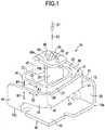
- FIG. 1 is a perspective view of the spring contact 1A.
- a compressive load is applied to the spring contact 1A from a direction indicated by the arrow Z1 in FIG. 1 .
- FIG. 2 is a front view of the spring contact 1A.
- a virtual line segment along the load applied to the spring contact 1A is referred to as a load action line X1 (illustrated in FIGS. 1 and 2 ).
- FIG. 3 is a plan view of the spring contact 1A viewed from a direction from which the load is applied.
- the spring contact 1A of this embodiment is formed by shaping a single springy metal plate M by precision pressing or the like, and includes a base 10 having a flat plate shape, a first elastic arm 11 that is part of the metal plate M and shaped into a helix, and a second elastic arm 12 that is also part of the metal plate M and shaped into a helix.
- the base 10, the first elastic arm 11, and the second elastic arm 12 are formed of a single metal plate. Therefore, the base 10, the first elastic arm 11, and the second elastic arm 12 are equal in thickness.
- first elastic arm 11 and the second elastic arm 12 may be formed of separate parts, and these elastic arms 11 and 12 may be fixed to the metal base 10 by fixing means such as welding or "joining through plastic deformation.”
- the material of the metal plate M is not limited in particular, and may be, for example, phosphor bronze subjected to anti-oxidation treatment such as gold plating, or springy stainless steel.
- an example of the base 10 has a substantially quadrangular shape. That is, this base 10 has a first side 10a, a second side 10b, a third side 10c, and a fourth side 10d.
- the dimensions of the base 10 are not limited in particular.
- the base 10 is compact in size with each of the sides 10a through 10d having a length of less than 2 mm, for example, a length of 1.4 mm.
- the first elastic arm 11 has a strip shape, and is bent into a helix as described below.
- the arrows A1 indicate the longitudinal directions of the first elastic arm 11, and the arrows B1 indicate the plate width directions of the first elastic arm 11.
- the second elastic arm 12 as well has a strip shape and is bent into a helix.
- the arrows A2 indicate the longitudinal directions of the second elastic arm 12, and the arrows B2 indicate the plate width directions of the second elastic arm 12.
- the length of the first elastic arm 11 is greater than the length of the second elastic arm 12.
- FIG. 4 is a schematic plan view of the first elastic arm 11 and the second elastic arm 12.
- the first elastic arm 11 is indicated by a solid line and the second elastic arm 12 is indicated by a dashed line.
- the first elastic arm 11 and the second elastic arm 12 are spirally wound, being spaced to avoid contacting each other. In some cases, part of the first elastic arm 11 and part of the second elastic arm 12 may contact each other.
- the first elastic arm 11 is helically wound such that the plate width directions (indicated by the arrows B1 in FIG. 1 ) are along the load action line X1, and a compressive load acts on the first elastic arm 11 in its plate width direction as in a volute spring.
- the second elastic arm 12 as well is helically wound such that the plate width directions (indicated by the arrows B2 in FIG. 1 ) are along the load action line X1, and a compressive load acts on the second elastic arm 12 in its plate width direction.
- the length of the first elastic arm 11 is greater than the length of the second elastic arm 12. Therefore, the spring constant (k1) of the first elastic arm 11 is smaller than the spring constant (k2) of the second elastic arm 12.
- the first elastic arm 11 includes a first fixed end 20 standing up substantially perpendicularly from the first side 10a (illustrated in FIG. 3 ) of the base 10, a first extending portion 21 extending in a direction along the first side 10a from the first fixed end 20, a first continuous portion 23 extending in a direction along the second side 10b via a curving portion 22, a first intermediate portion 25 extending in a direction along the third side 10c via a curving portion 24, a first extension portion 27 extending in a direction along the fourth side 10d via a curving portion 26, an end-side bending portion 28 bending into a U-shape, and a first end portion 29.
- the first end portion 29 is positioned at the free end of the first elastic arm 11.
- the first end portion 29 has a flat plate shape, and its plate surfaces extend in a direction along the load action line X1 (a vertical direction).
- a sharpened first contact 30 protruding in a direction along the load action line X1 is formed at the end of the first end portion 29.
- the first elastic arm 11 is helically shaped such that its turn angle is 360° or more (for example, approximately 450°).
- the term "turn angle" here is an angle from the first fixed end 20 to the first end portion 29 with a single turn around the load action line X1 being 360°.
- the first elastic arm 11 of this embodiment bends inward 90° at each of the three curving portions 22, 24 and 26 and further bends substantially 180° at the end-side bending portion 28. Therefore, with one turn being 360°, the turn angle of the first elastic arm 11 is approximately 450° (1.25 turns).
- the plate width of the first elastic arm 11 may be constant over the entire length of the first elastic arm 11. Alternatively, the first elastic arm 11 may taper to gradually decrease in plate width toward the first end portion 29 from the first fixed end 20.
- the first extending portion 21, the first continuous portion 23, the first intermediate portion 25, the first extension portion 27, and the curving portions 22, 24 and 26 serve as a spring effect part for effecting the deflection of the first elastic arm 11. That is, with the first elastic arm 11 deflecting with a load input from the first contact 30 to the first elastic arm 11 (a load in a direction along the load action line X1), the first elastic arm 11 stores elastic energy to generate a repulsive load.
- the second elastic arm 12 has a helical shape along the first elastic arm 11. That is, the second elastic arm 12 includes a second fixed end 40 standing up substantially perpendicularly from the third side 10c (illustrated in FIG. 3 ) of the base 10, a second extending portion 41 extending in a direction along the third side 10c from the second fixed end 40, a second continuous portion 43 extending in a direction along the fourth side 10d via a curving portion 42, a second intermediate portion 45 extending in a direction along the first side 10a via a curving portion 44, a second extension portion 47 extending in a direction along the second side 10b via a curving portion 46, and a second end portion 49.
- the fixed end 40 of the second elastic arm 12 is formed to extend from a side opposite to the fixed end 20 of the first elastic arm 11 across a flat plate, and the second elastic arm 12 has a helical shape along the first elastic arm 11. Therefore, it is possible to dispose the first elastic arm 11 and the second elastic arm 12 in a space-efficient manner.
- the second end portion 49 is positioned at the free end of the second elastic arm 12.
- the second end portion 49 has a flat plate shape, and its plate surfaces extend in a direction perpendicular to the load action line X1, namely, in a direction parallel to the base 10 (in a lateral direction).
- a pair of second contacts 50 and 51 are formed on an end face 49a of the second end portion 49.
- Each of the second contacts 50 and 51 has a conical shape protruding in a direction along the load action line X1 with the top of the protruding shape forming part of a spherical surface.
- an elongated through hole 52 is formed between the second contacts 50 and 51 in the second end portion 49. While this embodiment includes the two second contacts 50 and 51, the number of second contacts may be one or more than two.
- the second contacts 50 and 51 may have a pointed shape.
- the second elastic arm 12 is helically shaped such that its turn angle is 360° or less (for example, approximately 270°).
- the term "turn angle" here is an angle from the second fixed end 40 to the second end portion 49 with a single turn around the load action line X1 being 360°.
- the second elastic arm 12 of this embodiment bends inward 90° at each of the three curving portions 42, 44 and 46. Therefore, with one turn being 360°, the turn angle of the second elastic arm 12 is approximately 270° (0.75 turns).
- the plate width of the second elastic arm 12 may be constant over the entire length of the second elastic arm 12. Alternatively, the second elastic arm 12 may taper to gradually decrease in plate width toward the second end portion 49 from the second fixed end 40.
- the second extending portion 41, the second continuous portion 43, the second intermediate portion 45, the second extension portion 47, and the curving portions 42, 44 and 46 serve as a spring effect part for effecting the deflection of the second elastic arm 12. That is, with the second elastic arm 12 deflecting with a load input from the second contacts 50 and 51 to the second elastic arm 12 (a load in a direction along the load action line X1), the second elastic arm 12 stores elastic energy to generate a repulsive load.
- FIG. 2 illustrates the first elastic arm 11 and the second elastic arm 12 to which no external force (load) is applied (a free state).
- load no external force
- FIG. 2 illustrates the first elastic arm 11 and the second elastic arm 12 to which no external force (load) is applied (a free state).
- the first elastic arm 11 is elastically supported by the second elastic arm 12, so that an initial load (pre-tension) is applied to the first elastic arm 11.
- the first contact 30 passes through the through hole 52 of the second end portion 49 to protrude outward (upward in FIG. 2 ) from the end face 49a of the second end portion 49.
- the first contact 30 protrudes in a direction along the load action line X1 from the through hole 52 of the second end portion 49, and the first contact 30 is disposed between the second contacts 50 and 51 to be side by side with the second contacts 50 and 51 in a plane direction (a direction along the end face 49a) in a plan view.
- the end of the first contact 30 protrudes more than the ends of the second contacts 50 and 51 by a height H1 (illustrated in FIG. 2 ).
- the end face 29a of the first end portion 29 is placed on the side facing the back face 49b of the second end portion 49 with respect to a direction in which a load is applied (the load action line X1).
- the end face 29a of the first end portion 29 contacts the back face 49b of the second end portion 49 with elastic energy stored, so that an initial load is generated in the first elastic arm 11.
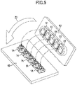
- FIG. 5 is a perspective view of an example of a first circuit board 60 on which multiple spring contacts 1A are disposed and a second circuit board 62 on which multiple connection target members 61 are disposed.
- the connection target members 61 each being a wiring pattern or a terminal, are disposed at positions each corresponding to one of the spring contacts 1A on the first circuit board 60.
- FIG. 6 illustrates the spring contact 1A to which a compressive load is applied by the connection target member 61 contacting the spring contact 1A.
- FIG. 7 illustrates a load-deflection relationship (a load-deflection characteristic) of the spring contact 1A.
- the first contact 30 contacts the connection target member 61. Therefore, the first contact 30 alone is independently pressed by the connection target member 61, so that the first elastic arm 11 alone deflects.
- the first elastic arm 11 is supported by the second end portion 49 with an initial load (pre-tension) applied to the first elastic arm 11. Therefore, an initial load P1 commensurate with the pre-tension (illustrated in FIG. 7 ) rises at the beginning of the contact of the first contact 30 with the connection target member 61.
- the load concentrates on the sharp end of the first contact 30, so that a great contact pressure is obtained. Even if a film having a high electric resistance value, such as an oxide film, is formed on the surface of the connection target member 61, it is possible to ensure a good electrical connection because the film is broken by the sharp end of the first contact 30.
- the first elastic arm 11 and the second elastic arm 12 both deflect. That is, as illustrated in FIG. 7 , when the load exceeds P2, a load that is generated in accordance with the spring constant of the second elastic arm 12 (a load-deflection characteristic indicated by a dashed line L2 in FIG. 7 ) is added to a load that is generated in accordance with the spring constant of the first elastic arm 11, and is applied to the connection target member 61.
- the spring constant of the spring contact 1A increases, which is the same as the spring constant of the second elastic arm 12 is added to the spring constant of the first elastic arm 11, thus resulting in a nonlinear load-deflection characteristic according to which the load increases after the load P2 as indicated by a solid line L3 in FIG. 7 .
- the first contact 30 is inserted in the through hole 52 formed in the second end portion 49, and the first contact 30 and the second contacts 50 and 51 each protrude in a direction from which a load acts.
- the second contacts 50 and 51 are separately disposed at symmetrical positions one on each side of the first contact 30.
- the first contact 30 on the load action line X1 being in the center, a contact pressure due to the first contact 30 and the second contacts 50 and 51 can be applied to the connection target member 61. Furthermore, because the first contact 30 in inserted in and guided by the through hole 52, it is possible to reduce deformation of the first elastic arm 11 of a small spring constant in a plane direction and also to reduce deformation of the second elastic arm 12 in a plane direction.
- the spring constant (k1) of the first elastic arm 11 and the spring constant (k2) of the second elastic arm 12 differ from each other so that the resonance frequency of the first elastic arm 11 and the resonance frequency of the second elastic arm 12 differ from each other.
- the length of the first elastic arm 11 is greater than the length of the second elastic arm 12. There is no substantial difference between the plate width of the first elastic arm 11 and the plate width of the second elastic arm 12.
- the spring constant (k1) of the first elastic arm 11 is made smaller than the spring constant (k2) of the second elastic arm 12, and the first elastic arm 11 and the second elastic arm 12 are caused to differ in resonance frequency from each other.
- FIG. 8 illustrates the metal plate M, which is the material of the spring contact 1A, blanked out from a metal plate by processing such as precision pressing.
- This metal plate M includes the base 10, a first portion M1 for the first elastic arm 11, and a second portion M2 for the second elastic arm 12.
- a length L4 of the first portion M1 is greater than a length L5 of the second portion M2.
- a thickness t of the metal plate M which is, for example, around 0.07 mm (0.04 to 0.12 mm), is not limited to this range, and is determined in accordance with the specifications of the spring contact 1A, such as size and a spring constant.
- the first contact 30 is formed at the end of the first portion M1.
- the second contacts 50 and 51 and the through hole 52 are formed at the end of the second portion M2.
- the first end portion 29 is formed by bending the end of the first portion M1 at a right angle. Furthermore, the second end portion 49 is formed by bending the end of the second portion M2 at a right angle.
- the first elastic arm 11 is formed by helically bending the first portion M1.
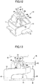
- the second elastic arm 12 is formed by helically bending the second portion M2. Thereafter, by bending the second elastic arm 12 at a substantially right angle in a direction indicated by the arrow Z3 in FIG. 11 , an intermediate product 1A' illustrated in FIG. 12 is obtained. According to this intermediate product 1A', the end face 29a of the first end portion 29 and the back face 49b of the second end portion 49 face each other, being apart from each other.
- the back face 49b of the second end portion 49 is brought into contact with the end face 29a of the first end portion 29, and the first elastic arm 11 and the second elastic arm 12 are simultaneously deflected.
- the first elastic arm 11 being within the elastic limit
- the first elastic arm 11 and the second elastic arm 12 are simultaneously deflected to a height at which the second elastic arm 12 goes beyond the elastic limit.
- the method of manufacturing the spring contact 1A of this embodiment includes the following processes:
- FIG. 13 illustrates a spring contact 1B according to a second embodiment.
- this spring contact 1B in a free state where no external force is applied, there is a gap commensurate with a height H2 between the end face 29a of the first end portion 29 and the back face 49b of the second end portion 49. Therefore, no initial load as described with respect to the spring contact 1A of the first embodiment is generated in the first elastic arm 11.
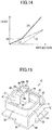
- FIG. 14 illustrates a load-deflection relationship of the spring contact 1B of the second embodiment.
- the second contacts 50 and 51 as well are pressed by the connection target member 61 to deflect the second elastic arm 12. Therefore, when the load exceeds P3, it becomes the same as the spring constant of the second elastic arm 12 (a load-deflection characteristic indicated by a dashed line L2 in FIG. 14 ) is added to the spring constant of the first elastic arm 11, thus resulting in a nonlinear load-deflection characteristic as indicated by a solid line L3.
- the spring contact 1B of the second embodiment is equal to the spring contact 1A of the first embodiment, and therefore, both are referred to using the same numerals and a description thereof is omitted.
- the spring constant of the first elastic arm 11 and the spring constant of the second elastic arm 12 are different from each other the same as in the spring contact 1A of the first embodiment. This makes it possible to prevent the first elastic arm 11 and the second elastic arm 12 from resonating simultaneously under vibrations of a particular frequency and causing the first contact 30 and the second contacts 50 and 51 to simultaneously separate from the connection target member 61, so that it is possible to avoid conduction failure due to vibrations.
- FIG. 15 illustrates a spring contact 1C according to a third embodiment.
- the first contact 30 is placed side by side with the second end portion 49 at a position off the second end portion 49 (a position offset relative to a side face of the second end portion 49) instead of forming the through hole 52 in the second end portion 49.
- the end of the first contact 30 protrudes outward (upward in FIG. 15 ) relative to the end face 49a of the second end portion 49.
- the number of first contacts 30 may be two or more, and the number of second contacts 50 and 51 may be one or more than two.
- the spring contact 1C of the third embodiment is equal to the spring contact 1A of the first embodiment, and therefore, both are referred to using the same numerals and a description thereof is omitted.
- spring contacts of the present invention may be applied to connections of circuits of various electronics, such as circuit parts of, for example, electronics to be installed in portable terminal devices, industrial machines, and transportation equipment including vehicles and airplanes, and medical devices.
- 1A, 1B, 1C ... spring contact, 10 ... base, 11 ... first elastic arm, 12 ... second elastic arm, 20 ... first fixed end, 29 ... first end portion, 29a ... end face, 30 ... first contact, 40 ... second fixed end, 49 ... second end portion, 49a ... end face, 49b ... back face, 50, 51 ... second contact, 52 ... through hole, 61 ... connection target member, M ... metal plate, X1 ... load action line
Landscapes
- Engineering & Computer Science (AREA)
- Manufacturing & Machinery (AREA)
- Coupling Device And Connection With Printed Circuit (AREA)
- Measuring Leads Or Probes (AREA)
- Manufacturing Of Electrical Connectors (AREA)
Abstract
Description
- The present invention relates to spring contacts to be applied to, for example, connecting parts of electronics, and in particular to a spring contact including a pair of elastic arms (a first elastic arm and a second elastic arm) and a method of manufacturing the same.
- For example, as contact means used for electrical connecting parts of electronics, a spring contact described in Patent Document 1 is known. According to the spring contact of Patent Document 1, however, a pair of elastic contact arms are formed in a planar double spiral, and therefore, it is difficult to reduce a mounting area necessary for mounting on electronics. Reducing the width of the elastic contact arms to reduce the mounting area decreases a spring constant, thus preventing a stable connection from being established. Therefore, a spring contact (spring connector) improved to allow reduction of the mounting area as illustrated in Patent Document 2 has been developed.
-
- Patent Document 1: Japanese Laid-open Patent Publication No.
2010-118256 - Patent Document 2: Japanese Laid-open Patent Publication No.
2016-1583 - The spring contact of Patent Document 2 includes a pair of elastic arms (a first elastic arm and a second elastic arm) that are helically wound, and a load acts on each elastic arm in a plate width direction as in a volute spring. Therefore, it is possible to place the elastic arms of a large spring constant compactly in a small mounting area. According to this, however, only a contact provided on the first elastic arm contacts a connection target member, and the second elastic arm operates as an auxiliary spring for the first elastic arm. Therefore, the electrical connection with the connection target member is established only through the contact provided on the first elastic arm. Therefore, a diligent study has been made to achieve a more reliable connection with respect to a spring contact advantageously characterized by a small mounting area.
- Accordingly, an object of the present invention is to provide a spring contact whose mounting area is small and that can establish a stable connection to a connection target member.
- One embodiment is a spring contact to which a compressive load is to be imposed that includes a base, a first elastic arm of a helical shape that includes a first fixed end supported on the base and a first end portion at a free end, a first contact provided at the first end portion and protruding in a direction from which the load acts, a second elastic arm of a helical shape that includes a second fixed end supported on the base and a second end portion at a free end, and a second contact provided at the second end portion, placed independent of the first contact, and protruding in the direction from which the load acts. According to this embodiment, the first elastic arm may be provided with an initial load. Furthermore, the spring constant of the first elastic arm and the spring constant of the second elastic arm may be different from each other.
- A method of manufacturing a spring contact according to one embodiment forms a first portion including a first contact and a second portion including a second contact in a material formed of a metal plate, forms a first elastic arm having a first spring constant and including a first end portion by helically bending the first portion, and forms a second elastic arm having a second spring constant greater than the first spring constant and including a second end portion by helically bending the second portion. The first end portion and the second end portion are disposed such that an end face of the first end portion faces a back face of the second end portion with respect to a direction in which a load is applied, and the first elastic arm and the second elastic arm are simultaneously deflected such that the second elastic arm goes beyond an elastic limit with the first elastic arm being within an elastic limit by imposing a compressive load simultaneously on the first end portion and the second end portion. Thereafter, with the load being removed, the end face of the first end portion is caused to contact the back face of the second end portion to cause an initial load to be generated in the first elastic arm, through the amount of spring back of the second elastic arm being smaller than the amount of spring back of the first elastic arm.
- According to a spring contact of the present invention, a first contact provided in a first elastic arm and a second contact provided in a second elastic arm contact a connection target member independent of each other, so that it is possible to establish a stable connection to the connection target member.
-
-
FIG. 1 is a perspective view of a spring contact according to a first embodiment. -
FIG. 2 is a front view of the spring contact illustrated inFIG. 1 . -
FIG. 3 is a plan view of the spring contact illustrated inFIG. 1 . -
FIG. 4 is a schematic plan view of a first elastic arm and a second elastic arm of the spring contact illustrated inFIG. 1 . -
FIG. 5 is a perspective view of an example of a circuit board on which the spring contacts illustrated inFIG. 1 are disposed and connection target members. -
FIG. 6 is a front view of the spring contact illustrated inFIG. 1 to which a load is imposed. -
FIG. 7 is a graph illustrating a load-deflection relationship of the spring contact illustrated inFIG. 1 . -
FIG. 8 is a perspective view of a material (metal plate) of the spring contact illustrated inFIG. 1 before bending. -
FIG. 9 is a perspective view of an intermediate product where part of the metal plate illustrated inFIG. 8 is bent. -
FIG. 10 is a perspective view illustrating a state where the first elastic arm is formed from the intermediate product illustrated inFIG. 9 . -
FIG. 11 is a perspective view illustrating a state where the second elastic arm is formed from the intermediate product illustrated inFIG. 10 . -
FIG. 12 is a perspective view illustrating a state where a fixed end of the second elastic arm of the intermediate product illustrated inFIG. 11 is bent at a right angle. -
FIG. 13 is a front view of a spring contact according to a second embodiment. -
FIG. 14 is a graph illustrating a load-deflection relationship of the spring contact illustrated inFIG. 13 . -
FIG. 15 is a perspective view of a spring contact according to a third embodiment. - A
spring contact 1A according to a first embodiment is described below with reference toFIGS. 1 through 12 . -
FIG. 1 is a perspective view of thespring contact 1A. A compressive load is applied to thespring contact 1A from a direction indicated by the arrow Z1 inFIG. 1 .FIG. 2 is a front view of thespring contact 1A. In this embodiment, for convenience of description, a virtual line segment along the load applied to thespring contact 1A is referred to as a load action line X1 (illustrated inFIGS. 1 and2 ).FIG. 3 is a plan view of thespring contact 1A viewed from a direction from which the load is applied. - The
spring contact 1A of this embodiment is formed by shaping a single springy metal plate M by precision pressing or the like, and includes abase 10 having a flat plate shape, a firstelastic arm 11 that is part of the metal plate M and shaped into a helix, and a secondelastic arm 12 that is also part of the metal plate M and shaped into a helix. Thebase 10, the firstelastic arm 11, and the secondelastic arm 12 are formed of a single metal plate. Therefore, thebase 10, the firstelastic arm 11, and the secondelastic arm 12 are equal in thickness. As another embodiment, the firstelastic arm 11 and the secondelastic arm 12 may be formed of separate parts, and theseelastic arms metal base 10 by fixing means such as welding or "joining through plastic deformation." The material of the metal plate M is not limited in particular, and may be, for example, phosphor bronze subjected to anti-oxidation treatment such as gold plating, or springy stainless steel. - As illustrated in
FIG. 3 , in a plan view of thespring contact 1A, an example of thebase 10 has a substantially quadrangular shape. That is, thisbase 10 has afirst side 10a, asecond side 10b, athird side 10c, and afourth side 10d. The dimensions of thebase 10 are not limited in particular. Depending on the size and the degree of integration of an electronic component in which thespring contact 1A is used, thebase 10 is compact in size with each of thesides 10a through 10d having a length of less than 2 mm, for example, a length of 1.4 mm. - The first
elastic arm 11 has a strip shape, and is bent into a helix as described below. InFIG. 1 , the arrows A1 indicate the longitudinal directions of the firstelastic arm 11, and the arrows B1 indicate the plate width directions of the firstelastic arm 11. The secondelastic arm 12 as well has a strip shape and is bent into a helix. InFIG. 1 , the arrows A2 indicate the longitudinal directions of the secondelastic arm 12, and the arrows B2 indicate the plate width directions of the secondelastic arm 12. The length of the firstelastic arm 11 is greater than the length of the secondelastic arm 12. -
FIG. 4 is a schematic plan view of the firstelastic arm 11 and the secondelastic arm 12. InFIG. 4 , the firstelastic arm 11 is indicated by a solid line and the secondelastic arm 12 is indicated by a dashed line. As illustrated inFIGS. 3 and 4 , in a plan view of thespring contact 1A, the firstelastic arm 11 and the secondelastic arm 12 are spirally wound, being spaced to avoid contacting each other. In some cases, part of the firstelastic arm 11 and part of the secondelastic arm 12 may contact each other. - The first
elastic arm 11 is helically wound such that the plate width directions (indicated by the arrows B1 inFIG. 1 ) are along the load action line X1, and a compressive load acts on the firstelastic arm 11 in its plate width direction as in a volute spring. The secondelastic arm 12 as well is helically wound such that the plate width directions (indicated by the arrows B2 inFIG. 1 ) are along the load action line X1, and a compressive load acts on the secondelastic arm 12 in its plate width direction. The length of the firstelastic arm 11 is greater than the length of the secondelastic arm 12. Therefore, the spring constant (k1) of the firstelastic arm 11 is smaller than the spring constant (k2) of the secondelastic arm 12. - An example of the first
elastic arm 11 includes a firstfixed end 20 standing up substantially perpendicularly from thefirst side 10a (illustrated inFIG. 3 ) of thebase 10, a first extendingportion 21 extending in a direction along thefirst side 10a from the firstfixed end 20, a firstcontinuous portion 23 extending in a direction along thesecond side 10b via a curvingportion 22, a firstintermediate portion 25 extending in a direction along thethird side 10c via a curvingportion 24, afirst extension portion 27 extending in a direction along thefourth side 10d via a curvingportion 26, an end-side bending portion 28 bending into a U-shape, and afirst end portion 29. - The
first end portion 29 is positioned at the free end of the firstelastic arm 11. Thefirst end portion 29 has a flat plate shape, and its plate surfaces extend in a direction along the load action line X1 (a vertical direction). A sharpenedfirst contact 30 protruding in a direction along the load action line X1 is formed at the end of thefirst end portion 29. - The first
elastic arm 11 is helically shaped such that its turn angle is 360° or more (for example, approximately 450°). The term "turn angle" here is an angle from the firstfixed end 20 to thefirst end portion 29 with a single turn around the load action line X1 being 360°. The firstelastic arm 11 of this embodiment bends inward 90° at each of the three curvingportions side bending portion 28. Therefore, with one turn being 360°, the turn angle of the firstelastic arm 11 is approximately 450° (1.25 turns). The plate width of the firstelastic arm 11 may be constant over the entire length of the firstelastic arm 11. Alternatively, the firstelastic arm 11 may taper to gradually decrease in plate width toward thefirst end portion 29 from the firstfixed end 20. - The first extending
portion 21, the firstcontinuous portion 23, the firstintermediate portion 25, thefirst extension portion 27, and the curvingportions elastic arm 11. That is, with the firstelastic arm 11 deflecting with a load input from thefirst contact 30 to the first elastic arm 11 (a load in a direction along the load action line X1), the firstelastic arm 11 stores elastic energy to generate a repulsive load. - The second
elastic arm 12 has a helical shape along the firstelastic arm 11. That is, the secondelastic arm 12 includes a secondfixed end 40 standing up substantially perpendicularly from thethird side 10c (illustrated inFIG. 3 ) of thebase 10, a second extendingportion 41 extending in a direction along thethird side 10c from the secondfixed end 40, a secondcontinuous portion 43 extending in a direction along thefourth side 10d via a curvingportion 42, a secondintermediate portion 45 extending in a direction along thefirst side 10a via a curvingportion 44, asecond extension portion 47 extending in a direction along thesecond side 10b via a curvingportion 46, and asecond end portion 49. Thus, thefixed end 40 of the secondelastic arm 12 is formed to extend from a side opposite to thefixed end 20 of the firstelastic arm 11 across a flat plate, and the secondelastic arm 12 has a helical shape along the firstelastic arm 11. Therefore, it is possible to dispose the firstelastic arm 11 and the secondelastic arm 12 in a space-efficient manner. - The
second end portion 49 is positioned at the free end of the secondelastic arm 12. Thesecond end portion 49 has a flat plate shape, and its plate surfaces extend in a direction perpendicular to the load action line X1, namely, in a direction parallel to the base 10 (in a lateral direction). A pair ofsecond contacts end face 49a of thesecond end portion 49. Each of thesecond contacts hole 52 is formed between thesecond contacts second end portion 49. While this embodiment includes the twosecond contacts second contacts - The second
elastic arm 12 is helically shaped such that its turn angle is 360° or less (for example, approximately 270°). The term "turn angle" here is an angle from the secondfixed end 40 to thesecond end portion 49 with a single turn around the load action line X1 being 360°. The secondelastic arm 12 of this embodiment bends inward 90° at each of the three curvingportions elastic arm 12 is approximately 270° (0.75 turns). The plate width of the secondelastic arm 12 may be constant over the entire length of the secondelastic arm 12. Alternatively, the secondelastic arm 12 may taper to gradually decrease in plate width toward thesecond end portion 49 from the secondfixed end 40. - The second extending
portion 41, the secondcontinuous portion 43, the secondintermediate portion 45, thesecond extension portion 47, and the curvingportions elastic arm 12. That is, with the secondelastic arm 12 deflecting with a load input from thesecond contacts elastic arm 12 stores elastic energy to generate a repulsive load. -
FIG. 2 illustrates the firstelastic arm 11 and the secondelastic arm 12 to which no external force (load) is applied (a free state). As illustrated inFIG. 2 , with anend face 29a of thefirst end portion 29 contacting aback face 49b of thesecond end portion 49, the firstelastic arm 11 is elastically supported by the secondelastic arm 12, so that an initial load (pre-tension) is applied to the firstelastic arm 11. Thefirst contact 30 passes through the throughhole 52 of thesecond end portion 49 to protrude outward (upward inFIG. 2 ) from theend face 49a of thesecond end portion 49. - As illustrated in
FIG. 2 , in the free state where no external force is applied to the firstelastic arm 11 and the secondelastic arm 12, thefirst contact 30 protrudes in a direction along the load action line X1 from the throughhole 52 of thesecond end portion 49, and thefirst contact 30 is disposed between thesecond contacts second contacts end face 49a) in a plan view. The end of thefirst contact 30 protrudes more than the ends of thesecond contacts FIG. 2 ). - Thus, according to the
spring contact 1A of this embodiment, theend face 29a of thefirst end portion 29 is placed on the side facing theback face 49b of thesecond end portion 49 with respect to a direction in which a load is applied (the load action line X1). In the free state where no load is applied, theend face 29a of thefirst end portion 29 contacts theback face 49b of thesecond end portion 49 with elastic energy stored, so that an initial load is generated in the firstelastic arm 11. -
FIG. 5 is a perspective view of an example of afirst circuit board 60 on whichmultiple spring contacts 1A are disposed and asecond circuit board 62 on which multipleconnection target members 61 are disposed. On thesecond circuit board 62, theconnection target members 61, each being a wiring pattern or a terminal, are disposed at positions each corresponding to one of thespring contacts 1A on thefirst circuit board 60. When thesecond circuit board 62 is placed over thefirst circuit board 60 as indicated by the arrow Z2 inFIG. 5 , thespring contacts 1A and the correspondingconnection target members 61 contact each other. -
FIG. 6 illustrates thespring contact 1A to which a compressive load is applied by theconnection target member 61 contacting thespring contact 1A.FIG. 7 illustrates a load-deflection relationship (a load-deflection characteristic) of thespring contact 1A. - During a transition from the free state illustrated in
FIG. 2 to a loaded state illustrated inFIG. 6 , first, thefirst contact 30 contacts theconnection target member 61. Therefore, thefirst contact 30 alone is independently pressed by theconnection target member 61, so that the firstelastic arm 11 alone deflects. The firstelastic arm 11 is supported by thesecond end portion 49 with an initial load (pre-tension) applied to the firstelastic arm 11. Therefore, an initial load P1 commensurate with the pre-tension (illustrated inFIG. 7 ) rises at the beginning of the contact of thefirst contact 30 with theconnection target member 61. - Therefore, the load concentrates on the sharp end of the
first contact 30, so that a great contact pressure is obtained. Even if a film having a high electric resistance value, such as an oxide film, is formed on the surface of theconnection target member 61, it is possible to ensure a good electrical connection because the film is broken by the sharp end of thefirst contact 30. - When the
spring contact 1A is further compressed by theconnection target member 61, so that the deflection of the firstelastic arm 11 increases, thesecond contacts connection target member 61 as illustrated inFIG. 6 . Therefore, the firstelastic arm 11 and the secondelastic arm 12 both deflect. That is, as illustrated inFIG. 7 , when the load exceeds P2, a load that is generated in accordance with the spring constant of the second elastic arm 12 (a load-deflection characteristic indicated by a dashed line L2 inFIG. 7 ) is added to a load that is generated in accordance with the spring constant of the firstelastic arm 11, and is applied to theconnection target member 61. Therefore, the spring constant of thespring contact 1A increases, which is the same as the spring constant of the secondelastic arm 12 is added to the spring constant of the firstelastic arm 11, thus resulting in a nonlinear load-deflection characteristic according to which the load increases after the load P2 as indicated by a solid line L3 inFIG. 7 . According to thespring contact 1A of this embodiment, thefirst contact 30 is inserted in the throughhole 52 formed in thesecond end portion 49, and thefirst contact 30 and thesecond contacts second contacts first contact 30. Therefore, with thefirst contact 30 on the load action line X1 being in the center, a contact pressure due to thefirst contact 30 and thesecond contacts connection target member 61. Furthermore, because thefirst contact 30 in inserted in and guided by the throughhole 52, it is possible to reduce deformation of the firstelastic arm 11 of a small spring constant in a plane direction and also to reduce deformation of the secondelastic arm 12 in a plane direction. - With the
first contact 30 and thesecond contacts connection target member 61 as illustrated inFIG. 6 , vibrations of various frequencies may be applied to thespring contact 1A or theconnection target member 61. Therefore, according to thespring contact 1A of this embodiment, the spring constant (k1) of the firstelastic arm 11 and the spring constant (k2) of the secondelastic arm 12 differ from each other so that the resonance frequency of the firstelastic arm 11 and the resonance frequency of the secondelastic arm 12 differ from each other. - According to this embodiment, the length of the first
elastic arm 11 is greater than the length of the secondelastic arm 12. There is no substantial difference between the plate width of the firstelastic arm 11 and the plate width of the secondelastic arm 12. By so doing, the spring constant (k1) of the firstelastic arm 11 is made smaller than the spring constant (k2) of the secondelastic arm 12, and the firstelastic arm 11 and the secondelastic arm 12 are caused to differ in resonance frequency from each other. - Therefore, even if vibrations of a particular frequency are applied to the
spring contact 1A or theconnection target member 61, it is possible to prevent the firstelastic arm 11 and the secondelastic arm 12 from resonating simultaneously and causing thefirst contact 30 and thesecond contacts connection target member 61, so that it is possible to avoid conduction failure due to vibrations. This also is effective in achieving good connection by thespring contact 1A. - Next, an example of a method of manufacturing the
spring contact 1A according to this embodiment is described with reference toFIGS. 8 through 12 . -
FIG. 8 illustrates the metal plate M, which is the material of thespring contact 1A, blanked out from a metal plate by processing such as precision pressing. This metal plate M includes thebase 10, a first portion M1 for the firstelastic arm 11, and a second portion M2 for the secondelastic arm 12. A length L4 of the first portion M1 is greater than a length L5 of the second portion M2. A thickness t of the metal plate M, which is, for example, around 0.07 mm (0.04 to 0.12 mm), is not limited to this range, and is determined in accordance with the specifications of thespring contact 1A, such as size and a spring constant. Thefirst contact 30 is formed at the end of the first portion M1. Thesecond contacts hole 52 are formed at the end of the second portion M2. - As illustrated in
FIG. 9 , thefirst end portion 29 is formed by bending the end of the first portion M1 at a right angle. Furthermore, thesecond end portion 49 is formed by bending the end of the second portion M2 at a right angle. - As illustrated in
FIG. 10 , the firstelastic arm 11 is formed by helically bending the first portion M1. - As illustrated in
FIG. 11 , the secondelastic arm 12 is formed by helically bending the second portion M2. Thereafter, by bending the secondelastic arm 12 at a substantially right angle in a direction indicated by the arrow Z3 inFIG. 11 , anintermediate product 1A' illustrated inFIG. 12 is obtained. According to thisintermediate product 1A', theend face 29a of thefirst end portion 29 and theback face 49b of thesecond end portion 49 face each other, being apart from each other. - By imposing a load from a direction indicated by the arrow Z4 in
FIG. 12 , theback face 49b of thesecond end portion 49 is brought into contact with theend face 29a of thefirst end portion 29, and the firstelastic arm 11 and the secondelastic arm 12 are simultaneously deflected. To be more specific, with the firstelastic arm 11 being within the elastic limit, the firstelastic arm 11 and the secondelastic arm 12 are simultaneously deflected to a height at which the secondelastic arm 12 goes beyond the elastic limit. - A greater permanent deformation is generated in the second
elastic arm 12 than in the firstelastic arm 11. Therefore, when the load is removed, the secondelastic arm 12, whose amount of spring back is limited, cannot return to its original height. Therefore, the height of thesecond end portion 49 is slightly less than before the load is imposed. In contrast, the firstelastic arm 11 tries to return to its original height through spring back. Therefore, as illustrated inFIG. 2 , theend face 29a of thefirst end portion 29 contacts theback face 49b of thesecond end portion 49 with elastic energy being stored, so that an initial load is generated in the firstelastic arm 11. - Thus, the method of manufacturing the
spring contact 1A of this embodiment includes the following processes: - (1) forming the first portion M1 including the
first contact 30 and the second portion M2 including thesecond contacts FIG. 8 ); - (2) forming the first
elastic arm 11 having a first spring constant by bending the first portion M1 (FIG. 10 ) ; - (3) forming the second
elastic arm 12 having a second spring constant greater than the first spring constant by bending the second portion M2 (FIG. 11 ); - (4) disposing the
first end portion 29 and thesecond end portion 49 such that theend face 29a of thefirst end portion 29 and theback face 49b of thesecond end portion 49 face each other with respect to a direction in which a load is applied (FIG. 12 ); - (5) simultaneously deflecting the first
elastic arm 11 and the secondelastic arm 12 such that the secondelastic arm 12 goes beyond the elastic limit with the firstelastic arm 11 being within the elastic limit by imposing a compressive load simultaneously on thefirst end portion 29 and thesecond end portion 49; and - (6) with the load being removed, causing the
end face 29a of thefirst end portion 29 to contact theback face 49b of thesecond end portion 49 and causing an initial load to be generated in the firstelastic arm 11, through the amount of spring back of the secondelastic arm 12 being smaller than the amount of spring back of the first elastic arm 11 (FIG. 2 ). - By adopting such a manufacturing method, it has been made possible to provide the first
elastic arm 11 with an initial load (pre-tension) through the process of imposing a load simultaneously on the firstelastic arm 11 and the secondelastic arm 12, using the fact that the spring constant of the firstelastic arm 11 is smaller than the spring constant of the second elastic arm 12 (the firstelastic arm 11 is longer than the second elastic arm 12) . -
FIG. 13 illustrates aspring contact 1B according to a second embodiment. According to thisspring contact 1B, in a free state where no external force is applied, there is a gap commensurate with a height H2 between theend face 29a of thefirst end portion 29 and theback face 49b of thesecond end portion 49. Therefore, no initial load as described with respect to thespring contact 1A of the first embodiment is generated in the firstelastic arm 11. -
FIG. 14 illustrates a load-deflection relationship of thespring contact 1B of the second embodiment. When the connection target member 61 (illustrated inFIG. 13 ) contacts thefirst contact 30, so that a load is imposed on thefirst contact 30, initially, the firstelastic arm 11 alone deflects and the deflection therefore increases with an increase in the load as indicated by L1 inFIG. 14 . - When the load exceeds P3 in
FIG. 14 , thesecond contacts connection target member 61 to deflect the secondelastic arm 12. Therefore, when the load exceeds P3, it becomes the same as the spring constant of the second elastic arm 12 (a load-deflection characteristic indicated by a dashed line L2 inFIG. 14 ) is added to the spring constant of the firstelastic arm 11, thus resulting in a nonlinear load-deflection characteristic as indicated by a solid line L3. In other configurations and actions, thespring contact 1B of the second embodiment is equal to thespring contact 1A of the first embodiment, and therefore, both are referred to using the same numerals and a description thereof is omitted. - In the
spring contact 1B of the second embodiment as well, the spring constant of the firstelastic arm 11 and the spring constant of the secondelastic arm 12 are different from each other the same as in thespring contact 1A of the first embodiment. This makes it possible to prevent the firstelastic arm 11 and the secondelastic arm 12 from resonating simultaneously under vibrations of a particular frequency and causing thefirst contact 30 and thesecond contacts connection target member 61, so that it is possible to avoid conduction failure due to vibrations. -
FIG. 15 illustrates aspring contact 1C according to a third embodiment. According to thisspring contact 1C, thefirst contact 30 is placed side by side with thesecond end portion 49 at a position off the second end portion 49 (a position offset relative to a side face of the second end portion 49) instead of forming the throughhole 52 in thesecond end portion 49. The end of thefirst contact 30 protrudes outward (upward inFIG. 15 ) relative to theend face 49a of thesecond end portion 49. The number offirst contacts 30 may be two or more, and the number ofsecond contacts spring contact 1C of the third embodiment is equal to thespring contact 1A of the first embodiment, and therefore, both are referred to using the same numerals and a description thereof is omitted. - Needless to say, in carrying out the present invention, various changes may be made in the specific shapes and arrangement of the base, the first elastic arm, and the second elastic arm of a spring contact and the form of a connection target part. Furthermore, spring contacts of the present invention may be applied to connections of circuits of various electronics, such as circuit parts of, for example, electronics to be installed in portable terminal devices, industrial machines, and transportation equipment including vehicles and airplanes, and medical devices.
- The present international application is based on and claims priority to Japanese patent application No.
2016-120894, filed on June 17, 2017 - 1A, 1B, 1C ... spring contact, 10 ... base, 11 ... first elastic arm, 12 ... second elastic arm, 20 ... first fixed end, 29 ... first end portion, 29a ... end face, 30 ... first contact, 40 ... second fixed end, 49 ... second end portion, 49a ... end face, 49b ... back face, 50, 51 ... second contact, 52 ... through hole, 61 ... connection target member, M ... metal plate, X1 ... load action line
Claims (7)
- A spring contact to which a compressive load is to be imposed, the spring contact comprising:a base;a first elastic arm of a helical shape, including a first fixed end supported on the base and a first end portion at a free end;a first contact provided at the first end portion and protruding in a direction from which the load acts;a second elastic arm of a helical shape, including a second fixed end supported on the base and a second end portion at a free end; anda second contact provided at the second end portion, the second contact being placed independent of the first contact and protruding in the direction from which the load acts.
- The spring contact as claimed in claim 1, wherein an end face of the first end portion is placed to face a back face of the second end portion with respect to a direction in which the load is imposed, and in a free state where the load is not applied, an initial load is generated in the first elastic arm with the first end portion contacting the second end portion.
- The spring contact as claimed in claim 1 or 2, wherein the second end portion includes a through hole, and the first contact is inserted in the through hole to have an end thereof protruding outward from the second end portion.
- The spring contact as claimed in claim 1, wherein a spring constant of the first elastic arm and a spring constant of the second elastic arm are different from each other.
- The spring contact as claimed in claim 4, wherein the spring constant of the first elastic arm is smaller than the spring constant of the second elastic arm.
- The spring contact as claimed in claim 5, wherein a length of the first elastic arm is greater than a length of the second elastic arm.
- A method of manufacturing a spring contact, comprising:forming a first portion including a first contact and a second portion including a second contact in a material formed of a metal plate;forming a first elastic arm having a first spring constant and including a first end portion by helically bending the first portion;forming a second elastic arm having a second spring constant greater than the first spring constant and including a second end portion by helically bending the second portion;disposing the first end portion and the second end portion such that an end face of the first end portion faces a back face of the second end portion with respect to a direction in which a load is applied;simultaneously deflecting the first elastic arm and the second elastic arm such that the second elastic arm goes beyond an elastic limit with the first elastic arm being within an elastic limit by imposing a compressive load simultaneously on the first end portion and the second end portion; andwith the load being removed, causing the end face of the first end portion to contact the back face of the second end portion and causing an initial load to be generated in the first elastic arm, through an amount of spring back of the second elastic arm being smaller than an amount of spring back of the first elastic arm.
Applications Claiming Priority (2)
| Application Number | Priority Date | Filing Date | Title |
|---|---|---|---|
| JP2016120894 | 2016-06-17 | ||
| PCT/JP2017/020573 WO2017217253A1 (en) | 2016-06-17 | 2017-06-02 | Pressure contact and method for manufacturing same |
Publications (2)
| Publication Number | Publication Date |
|---|---|
| EP3474387A1 true EP3474387A1 (en) | 2019-04-24 |
| EP3474387A4 EP3474387A4 (en) | 2020-05-06 |
Family
ID=60664056
Family Applications (1)
| Application Number | Title | Priority Date | Filing Date |
|---|---|---|---|
| EP17813155.3A Withdrawn EP3474387A4 (en) | 2016-06-17 | 2017-06-02 | Pressure contact and method for manufacturing same |
Country Status (7)
| Country | Link |
|---|---|
| US (1) | US10446966B2 (en) |
| EP (1) | EP3474387A4 (en) |
| JP (1) | JP6668470B2 (en) |
| KR (1) | KR102102293B1 (en) |
| CN (1) | CN109075482A (en) |
| TW (1) | TWI649923B (en) |
| WO (1) | WO2017217253A1 (en) |
Families Citing this family (3)
| Publication number | Priority date | Publication date | Assignee | Title |
|---|---|---|---|---|
| CN105938949B (en) * | 2016-05-31 | 2020-04-21 | 深圳市信维通信股份有限公司 | Rectangular impact-resistant elastic sheet connector |
| JP6778596B2 (en) * | 2016-11-30 | 2020-11-04 | アルプスアルパイン株式会社 | Pressure welding connector and its manufacturing method |
| WO2018120505A1 (en) * | 2016-12-26 | 2018-07-05 | 华为技术有限公司 | Elastic piece and terminal |
Family Cites Families (23)
| Publication number | Priority date | Publication date | Assignee | Title |
|---|---|---|---|---|
| US5297967A (en) * | 1992-10-13 | 1994-03-29 | International Business Machines Corporation | Electrical interconnector with helical contacting portion and assembly using same |
| JP3315313B2 (en) * | 1996-05-17 | 2002-08-19 | 矢崎総業株式会社 | Connector structure |
| US6626708B2 (en) * | 2001-03-30 | 2003-09-30 | Tyco Electronics Corporation | Single piece spring contact |
| JP2002329542A (en) * | 2001-05-02 | 2002-11-15 | Shin Etsu Polymer Co Ltd | Press contact type adapter |
| JP3878041B2 (en) * | 2002-03-22 | 2007-02-07 | 株式会社日本マイクロニクス | Contact and electrical connection device using the same |
| JP3814231B2 (en) * | 2002-06-10 | 2006-08-23 | 株式会社アドバンストシステムズジャパン | Spiral contactor and manufacturing method thereof, semiconductor inspection apparatus using the same, and electronic component |
| JP2005129428A (en) * | 2003-10-27 | 2005-05-19 | Sumitomo Electric Ind Ltd | Bamboo child contact manufacturing method, contact manufactured by the method, and inspection apparatus or electronic device including the contact |
| US6855010B1 (en) * | 2004-01-26 | 2005-02-15 | Chuan Yi Precision Industry Co., Ltd. | Terminal for electric connector for communication apparatus |
| US7833256B2 (en) * | 2004-04-16 | 2010-11-16 | Biedermann Motech Gmbh | Elastic element for the use in a stabilization device for bones and vertebrae and method for the manufacture of such elastic element |
| US7393214B2 (en) * | 2006-02-17 | 2008-07-01 | Centipede Systems, Inc. | High performance electrical connector |
| KR101106506B1 (en) * | 2008-08-07 | 2012-01-20 | 박상량 | Flat folding coil spring, pogo pin using the same and manufacturing method thereof |
| JP2012021773A (en) * | 2008-11-12 | 2012-02-02 | Alps Electric Co Ltd | Spherical shell type contact and method for manufacturing the same |
| JP2010118256A (en) | 2008-11-13 | 2010-05-27 | Advanced Systems Japan Inc | Spiral contactor and method of manufacturing the same |
| US8263879B2 (en) * | 2009-11-06 | 2012-09-11 | International Business Machines Corporation | Axiocentric scrubbing land grid array contacts and methods for fabrication |
| US8959764B2 (en) * | 2009-11-06 | 2015-02-24 | International Business Machines Corporation | Metallurgical clamshell methods for micro land grid array fabrication |
| US8118604B2 (en) * | 2010-05-06 | 2012-02-21 | Hon Hai Precision Ind. Co., Ltd. | Socket connector having electrical element supported by insulated elastomer |
| US8690602B2 (en) * | 2011-02-17 | 2014-04-08 | Corning Gilbert Inc. | Blind mate interconnect and contact |
| JP2013055035A (en) * | 2011-08-09 | 2013-03-21 | Yokowo Co Ltd | Connector |
| DE202011108052U1 (en) * | 2011-11-18 | 2011-12-06 | Rosenberger Hochfrequenztechnik Gmbh & Co. Kg | connecting element |
| EP2680372B1 (en) * | 2012-06-29 | 2017-06-07 | Corning Optical Communications RF LLC | Multi-sectional insulator for coaxial connector |
| EP2680371B1 (en) * | 2012-06-29 | 2018-04-11 | Corning Optical Communications RF LLC | Tubular insulator for coaxial connector |
| US9570828B2 (en) * | 2012-10-03 | 2017-02-14 | Corad Technology Inc. | Compressible pin assembly having frictionlessly connected contact elements |
| JP6224551B2 (en) * | 2014-05-23 | 2017-11-01 | アルプス電気株式会社 | Pressure contact connector and manufacturing method thereof |
-
2017
- 2017-04-25 TW TW106113798A patent/TWI649923B/en active
- 2017-06-02 KR KR1020187036461A patent/KR102102293B1/en active Active
- 2017-06-02 EP EP17813155.3A patent/EP3474387A4/en not_active Withdrawn
- 2017-06-02 JP JP2018523655A patent/JP6668470B2/en active Active
- 2017-06-02 WO PCT/JP2017/020573 patent/WO2017217253A1/en not_active Ceased
- 2017-06-02 CN CN201780026788.5A patent/CN109075482A/en active Pending
-
2018
- 2018-11-27 US US16/200,794 patent/US10446966B2/en active Active
Also Published As
| Publication number | Publication date |
|---|---|
| TWI649923B (en) | 2019-02-01 |
| KR102102293B1 (en) | 2020-04-20 |
| TW201807897A (en) | 2018-03-01 |
| US10446966B2 (en) | 2019-10-15 |
| CN109075482A (en) | 2018-12-21 |
| JPWO2017217253A1 (en) | 2019-03-28 |
| WO2017217253A1 (en) | 2017-12-21 |
| KR20190008910A (en) | 2019-01-25 |
| EP3474387A4 (en) | 2020-05-06 |
| US20190097345A1 (en) | 2019-03-28 |
| JP6668470B2 (en) | 2020-03-18 |
Similar Documents
| Publication | Publication Date | Title |
|---|---|---|
| JP5615157B2 (en) | Connector and contact used for it | |
| JP5454646B1 (en) | Electrical connector | |
| US8845339B2 (en) | Connector having a housing with a fitting guide fitted with reinforcing metal fittings | |
| JP3860823B2 (en) | Connector and portable terminal equipped with this connector | |
| JP5748378B2 (en) | Connector and contact used for it | |
| US20070264854A1 (en) | Connector, and portable terminal equipment including the connector | |
| JP6349346B2 (en) | Contact and connector using the contact | |
| US10446966B2 (en) | Spring contact and method of manufacturing same | |
| KR20020045557A (en) | Switch exhibiting non-unidirectional displacement | |
| CN103001034A (en) | Electric connector | |
| WO2016170865A1 (en) | Press-fit terminal | |
| CN107968273A (en) | Substrate-substrate connector | |
| US9022817B2 (en) | Connector terminal including limiter extending along first and second spring terminals | |
| JP2002025674A (en) | Connection terminal | |
| WO2017179548A1 (en) | Crimp contact | |
| JP2021093345A (en) | Press-fit terminal, substrate with press-fit terminal, and equipment | |
| JP2016219097A (en) | Contact connection structure | |
| WO2023017766A1 (en) | Connector and electronic device | |
| JP5692346B1 (en) | Press-fit connector terminal and manufacturing method thereof | |
| KR102639004B1 (en) | Connector | |
| KR102639003B1 (en) | Connector | |
| US20160240943A1 (en) | Sim connector | |
| JP5933218B2 (en) | Terminal fitting with terminals at both ends | |
| US20250372326A1 (en) | Relay | |
| JP6829082B2 (en) | Pressure welding connector |
Legal Events
| Date | Code | Title | Description |
|---|---|---|---|
| STAA | Information on the status of an ep patent application or granted ep patent |
Free format text: STATUS: THE INTERNATIONAL PUBLICATION HAS BEEN MADE |
|
| PUAI | Public reference made under article 153(3) epc to a published international application that has entered the european phase |
Free format text: ORIGINAL CODE: 0009012 |
|
| STAA | Information on the status of an ep patent application or granted ep patent |
Free format text: STATUS: REQUEST FOR EXAMINATION WAS MADE |
|
| 17P | Request for examination filed |
Effective date: 20181206 |
|
| AK | Designated contracting states |
Kind code of ref document: A1 Designated state(s): AL AT BE BG CH CY CZ DE DK EE ES FI FR GB GR HR HU IE IS IT LI LT LU LV MC MK MT NL NO PL PT RO RS SE SI SK SM TR |
|
| AX | Request for extension of the european patent |
Extension state: BA ME |
|
| DAV | Request for validation of the european patent (deleted) | ||
| DAX | Request for extension of the european patent (deleted) | ||
| RIC1 | Information provided on ipc code assigned before grant |
Ipc: H01R 13/24 20060101AFI20191217BHEP Ipc: H01R 43/16 20060101ALI20191217BHEP |
|
| A4 | Supplementary search report drawn up and despatched |
Effective date: 20200408 |
|
| RIC1 | Information provided on ipc code assigned before grant |
Ipc: H01R 43/16 20060101ALI20200402BHEP Ipc: H01R 13/24 20060101AFI20200402BHEP |
|
| STAA | Information on the status of an ep patent application or granted ep patent |
Free format text: STATUS: THE APPLICATION HAS BEEN WITHDRAWN |
|
| 18W | Application withdrawn |
Effective date: 20200916 |