EP3474382A1 - Socket - Google Patents
Socket Download PDFInfo
- Publication number
- EP3474382A1 EP3474382A1 EP18193449.8A EP18193449A EP3474382A1 EP 3474382 A1 EP3474382 A1 EP 3474382A1 EP 18193449 A EP18193449 A EP 18193449A EP 3474382 A1 EP3474382 A1 EP 3474382A1
- Authority
- EP
- European Patent Office
- Prior art keywords
- bar
- shaped wire
- connection terminal
- socket
- external wiring
- Prior art date
- Legal status (The legal status is an assumption and is not a legal conclusion. Google has not performed a legal analysis and makes no representation as to the accuracy of the status listed.)
- Withdrawn
Links
- 238000009413 insulation Methods 0.000 claims description 13
- 238000004519 manufacturing process Methods 0.000 abstract description 11
- 238000003780 insertion Methods 0.000 description 15
- 230000037431 insertion Effects 0.000 description 15
- WABPQHHGFIMREM-UHFFFAOYSA-N lead(0) Chemical compound [Pb] WABPQHHGFIMREM-UHFFFAOYSA-N 0.000 description 6
- 229910000679 solder Inorganic materials 0.000 description 6
- 210000000078 claw Anatomy 0.000 description 4
- 239000000463 material Substances 0.000 description 4
- 239000002184 metal Substances 0.000 description 4
- 238000004080 punching Methods 0.000 description 4
- 239000011347 resin Substances 0.000 description 3
- 229920005989 resin Polymers 0.000 description 3
- 230000000694 effects Effects 0.000 description 2
- 238000000034 method Methods 0.000 description 2
- 238000005192 partition Methods 0.000 description 2
- 238000003825 pressing Methods 0.000 description 2
- 238000005476 soldering Methods 0.000 description 2
- 230000007423 decrease Effects 0.000 description 1
Images


Classifications
-
- H—ELECTRICITY
- H01—ELECTRIC ELEMENTS
- H01R—ELECTRICALLY-CONDUCTIVE CONNECTIONS; STRUCTURAL ASSOCIATIONS OF A PLURALITY OF MUTUALLY-INSULATED ELECTRICAL CONNECTING ELEMENTS; COUPLING DEVICES; CURRENT COLLECTORS
- H01R9/00—Structural associations of a plurality of mutually-insulated electrical connecting elements, e.g. terminal strips or terminal blocks; Terminals or binding posts mounted upon a base or in a case; Bases therefor
- H01R9/22—Bases, e.g. strip, block, panel
- H01R9/24—Terminal blocks
- H01R9/2408—Modular blocks
-
- H—ELECTRICITY
- H01—ELECTRIC ELEMENTS
- H01R—ELECTRICALLY-CONDUCTIVE CONNECTIONS; STRUCTURAL ASSOCIATIONS OF A PLURALITY OF MUTUALLY-INSULATED ELECTRICAL CONNECTING ELEMENTS; COUPLING DEVICES; CURRENT COLLECTORS
- H01R4/00—Electrically-conductive connections between two or more conductive members in direct contact, i.e. touching one another; Means for effecting or maintaining such contact; Electrically-conductive connections having two or more spaced connecting locations for conductors and using contact members penetrating insulation
- H01R4/24—Connections using contact members penetrating or cutting insulation or cable strands
- H01R4/2416—Connections using contact members penetrating or cutting insulation or cable strands the contact members having insulation-cutting edges, e.g. of tuning fork type
- H01R4/242—Connections using contact members penetrating or cutting insulation or cable strands the contact members having insulation-cutting edges, e.g. of tuning fork type the contact members being plates having a single slot
- H01R4/2425—Flat plates, e.g. multi-layered flat plates
- H01R4/2429—Flat plates, e.g. multi-layered flat plates mounted in an insulating base
-
- H—ELECTRICITY
- H01—ELECTRIC ELEMENTS
- H01R—ELECTRICALLY-CONDUCTIVE CONNECTIONS; STRUCTURAL ASSOCIATIONS OF A PLURALITY OF MUTUALLY-INSULATED ELECTRICAL CONNECTING ELEMENTS; COUPLING DEVICES; CURRENT COLLECTORS
- H01R11/00—Individual connecting elements providing two or more spaced connecting locations for conductive members which are, or may be, thereby interconnected, e.g. end pieces for wires or cables supported by the wire or cable and having means for facilitating electrical connection to some other wire, terminal, or conductive member, blocks of binding posts
- H01R11/01—Individual connecting elements providing two or more spaced connecting locations for conductive members which are, or may be, thereby interconnected, e.g. end pieces for wires or cables supported by the wire or cable and having means for facilitating electrical connection to some other wire, terminal, or conductive member, blocks of binding posts characterised by the form or arrangement of the conductive interconnection between the connecting locations
-
- H—ELECTRICITY
- H01—ELECTRIC ELEMENTS
- H01R—ELECTRICALLY-CONDUCTIVE CONNECTIONS; STRUCTURAL ASSOCIATIONS OF A PLURALITY OF MUTUALLY-INSULATED ELECTRICAL CONNECTING ELEMENTS; COUPLING DEVICES; CURRENT COLLECTORS
- H01R11/00—Individual connecting elements providing two or more spaced connecting locations for conductive members which are, or may be, thereby interconnected, e.g. end pieces for wires or cables supported by the wire or cable and having means for facilitating electrical connection to some other wire, terminal, or conductive member, blocks of binding posts
- H01R11/03—Individual connecting elements providing two or more spaced connecting locations for conductive members which are, or may be, thereby interconnected, e.g. end pieces for wires or cables supported by the wire or cable and having means for facilitating electrical connection to some other wire, terminal, or conductive member, blocks of binding posts characterised by the relationship between the connecting locations
- H01R11/05—Individual connecting elements providing two or more spaced connecting locations for conductive members which are, or may be, thereby interconnected, e.g. end pieces for wires or cables supported by the wire or cable and having means for facilitating electrical connection to some other wire, terminal, or conductive member, blocks of binding posts characterised by the relationship between the connecting locations the connecting locations having different types of direct connections
-
- H—ELECTRICITY
- H01—ELECTRIC ELEMENTS
- H01R—ELECTRICALLY-CONDUCTIVE CONNECTIONS; STRUCTURAL ASSOCIATIONS OF A PLURALITY OF MUTUALLY-INSULATED ELECTRICAL CONNECTING ELEMENTS; COUPLING DEVICES; CURRENT COLLECTORS
- H01R13/00—Details of coupling devices of the kinds covered by groups H01R12/70 or H01R24/00 - H01R33/00
- H01R13/46—Bases; Cases
- H01R13/502—Bases; Cases composed of different pieces
-
- H—ELECTRICITY
- H01—ELECTRIC ELEMENTS
- H01R—ELECTRICALLY-CONDUCTIVE CONNECTIONS; STRUCTURAL ASSOCIATIONS OF A PLURALITY OF MUTUALLY-INSULATED ELECTRICAL CONNECTING ELEMENTS; COUPLING DEVICES; CURRENT COLLECTORS
- H01R4/00—Electrically-conductive connections between two or more conductive members in direct contact, i.e. touching one another; Means for effecting or maintaining such contact; Electrically-conductive connections having two or more spaced connecting locations for conductors and using contact members penetrating insulation
- H01R4/02—Soldered or welded connections
- H01R4/023—Soldered or welded connections between cables or wires and terminals
-
- H—ELECTRICITY
- H01—ELECTRIC ELEMENTS
- H01R—ELECTRICALLY-CONDUCTIVE CONNECTIONS; STRUCTURAL ASSOCIATIONS OF A PLURALITY OF MUTUALLY-INSULATED ELECTRICAL CONNECTING ELEMENTS; COUPLING DEVICES; CURRENT COLLECTORS
- H01R4/00—Electrically-conductive connections between two or more conductive members in direct contact, i.e. touching one another; Means for effecting or maintaining such contact; Electrically-conductive connections having two or more spaced connecting locations for conductors and using contact members penetrating insulation
- H01R4/28—Clamped connections, spring connections
- H01R4/48—Clamped connections, spring connections utilising a spring, clip, or other resilient member
- H01R4/4809—Clamped connections, spring connections utilising a spring, clip, or other resilient member using a leaf spring to bias the conductor toward the busbar
-
- H—ELECTRICITY
- H01—ELECTRIC ELEMENTS
- H01R—ELECTRICALLY-CONDUCTIVE CONNECTIONS; STRUCTURAL ASSOCIATIONS OF A PLURALITY OF MUTUALLY-INSULATED ELECTRICAL CONNECTING ELEMENTS; COUPLING DEVICES; CURRENT COLLECTORS
- H01R9/00—Structural associations of a plurality of mutually-insulated electrical connecting elements, e.g. terminal strips or terminal blocks; Terminals or binding posts mounted upon a base or in a case; Bases therefor
- H01R9/22—Bases, e.g. strip, block, panel
- H01R9/24—Terminal blocks
- H01R9/2425—Structural association with built-in components
-
- H—ELECTRICITY
- H01—ELECTRIC ELEMENTS
- H01R—ELECTRICALLY-CONDUCTIVE CONNECTIONS; STRUCTURAL ASSOCIATIONS OF A PLURALITY OF MUTUALLY-INSULATED ELECTRICAL CONNECTING ELEMENTS; COUPLING DEVICES; CURRENT COLLECTORS
- H01R9/00—Structural associations of a plurality of mutually-insulated electrical connecting elements, e.g. terminal strips or terminal blocks; Terminals or binding posts mounted upon a base or in a case; Bases therefor
- H01R9/22—Bases, e.g. strip, block, panel
- H01R9/24—Terminal blocks
- H01R9/26—Clip-on terminal blocks for side-by-side rail- or strip-mounting
-
- H—ELECTRICITY
- H01—ELECTRIC ELEMENTS
- H01R—ELECTRICALLY-CONDUCTIVE CONNECTIONS; STRUCTURAL ASSOCIATIONS OF A PLURALITY OF MUTUALLY-INSULATED ELECTRICAL CONNECTING ELEMENTS; COUPLING DEVICES; CURRENT COLLECTORS
- H01R13/00—Details of coupling devices of the kinds covered by groups H01R12/70 or H01R24/00 - H01R33/00
- H01R13/46—Bases; Cases
- H01R13/502—Bases; Cases composed of different pieces
- H01R13/506—Bases; Cases composed of different pieces assembled by snap action of the parts
Definitions
- the disclosure relates to a socket having an external wiring connection terminal which is connected to an external wiring and an electrical device terminal connection terminal which is connected to an electrical device terminal.
- Japanese Laid-open No. 2003-346939 discloses a socket having an external wiring connection terminal which is connected to an external wiring, and an electrical device terminal connection terminal which is connected to an electrical device terminal.
- the external wiring connection terminal and the electrical device terminal connection terminal are connected by a coated lead wire, and the lead wire is soldered to both the external wiring connection terminal and the electrical device terminal connection terminal. Therefore, it takes time to assemble them.
- the lead wire is not suitable for automatic assembly because a shape thereof is not fixed and it is easily deformed by its own weight or an external force.
- the socket according to the related art configured to connect the terminals with a flat plate punched member formed of metal
- various types of flat plate punched members having complicated shapes are required according to wiring positions.
- shapes of the flat plate punched member may be 8 types. Therefore, the number of mold surfaces required to manufacture each of the flat plate punched materials is also increased to, for example, 16 according to the large number of types of the flat plate punched members. In addition, there is a lot of material loss due to punching, and as a result, manufacturing cost of the socket increases.
- An aspect of the present disclosure provides a socket which allows efficient and simple connection between a connection terminal for an external wiring and a connection terminal for an electrical device terminal, and in which costs and a number of operations therefor are reduced.
- a socket including an external wiring connection terminal which is connected to an external wiring and an electrical device terminal connection terminal which is connected to an electrical device terminal, wherein the external wiring connection terminal and the electrical device terminal connection terminal are electrically connected by a bar-shaped wire of which a shape is fixed to a predetermined shape.
- the external wiring connection terminal and the electrical device terminal connection terminal are electrically connected by the bar-shaped wire of which the shape is fixed in a predetermined shape.
- the bar-shaped wire of which the shape is fixed to a predetermined shape is different from a coated lead wire of which a shape is not fixed and which is easily deformed by its own weight or an external force.
- the bar-shaped wire of which the shape is fixed to a predetermined shape can be formed of a bare metal wire, automatic assembly becomes possible.
- the inter-terminal connection member is formed of the bar-shaped wire of which the shape is fixed in a predetermined shape.
- a pair of bilaterally symmetrical flat plate punched members may be required.
- the inter-terminal connection member is formed of the bar-shaped wire
- the bar-shaped wire itself can be formed into a symmetrical shape.
- material cost associated with the large number of types of inter-terminal connection members it is possible to reduce material cost associated with the large number of types of inter-terminal connection members.
- the number of types of inter-terminal connection members can be reduced, it is not necessary to select the type of bar-shaped wire, and the number of steps can be reduced.
- the bar-shaped wire may be formed in a U-shape.
- the bar-shaped wire is formed in such a way that the shape thereof is fixed in a U shape as a predetermined shape. Therefore, for example, it is possible to connect the bar-shaped wire to the external wiring connection terminal and the electrical device terminal connection terminal by pushing both ends of the bar-shaped wire fixed in a U shape upon connection to the external wiring connection terminal and the electrical device terminal connection terminal in the inter-terminal connection member.
- the bar-shaped wire can be connected to the external wiring connection terminal and the electrical device terminal connection terminal by moving the bar-shaped wire in one direction.
- the inter-terminal connection member is formed into a bar-shaped wire, the number of types of inter-terminal connection member can be reduced. Therefore, the automatic assembly is facilitated, the number of steps can be reduced and the manufacturing cost can be reduced.
- a molded product which supports the bar-shaped wire may be provided, and the molded product may have a groove or hole which fixes the bar-shaped wire in a stationary state in a direction perpendicular to a direction in which the bar-shaped wire is inserted into the molded product.
- the molded product which supports the bar-shaped wire is provided, and the molded product has the groove or hole which fixes the bar-shaped wire in the stationary state in the direction perpendicular to the direction in which the bar-shaped wire is inserted into the molded product. Accordingly, the bar-shaped wire does not move in the direction perpendicular to the direction in which the bar-shaped wire is inserted into the molded product due to the groove or hole of the molded product.
- a plurality of bar-shaped wires may be provided, and the molded product may support the bar-shaped wires to have a height difference between the bar-shaped wires in a direction in which the bar-shaped wire is inserted into the molded product.
- the molded product supports the bar-shaped wires to have a height difference between the bar-shaped wires in a direction in which the bar-shaped wire is inserted into the molded product.
- a plurality of bar-shaped wires may be provided, and the molded product may have insulation walls which insulate the plurality of bar-shaped wires.
- the molded product has the insulation walls which insulate the plurality of bar-shaped wires. Therefore, it is possible to prevent short-circuiting of the bar-shaped wires with each other due to the insulation walls.
- each of the external wiring connection terminal and the electrical device terminal connection terminal may have a bar-shaped wire end connection hole which enables electrical connection by inserting each end of the bar-shaped wire.
- the bar-shaped wire when the bar-shaped wire is inserted to connect the bar-shaped wire to the external wiring connection terminal and the electrical device terminal connection terminal, the bar-shaped wire can be connected to the external wiring connection terminal and the electrical device terminal connection terminal merely by inserting the bar-shaped wire into the respective bar-shaped wire end connection holes of the external wiring connection terminal and the electrical device terminal connection terminal.
- a cover body having an insulating property may be provided, and the cover body may have a protrusion which fixes a position of the bar-shaped wire when the cover body is closed.
- the protrusion of the cover body fixes the position of the bar-shaped wire. Therefore, it is possible to prevent disconnection of the bar-shaped wire from the external wiring connection terminal and the electrical device terminal connection terminal. Further, when the bar-shaped wire is connected to the external wiring connection terminal, for example, it can be soldered to the external wiring connection terminal while the bar-shaped wire is placed on the protrusion of the cover body. As a result, it is easy to solder the bar-shaped wire to the external wiring connection terminal.
- this embodiment an embodiment according to an aspect of the disclosure (hereinafter, also referred to as “this embodiment”) will be described with reference to the drawings.
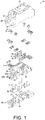
- FIG. 1 illustrates an example of a socket 1A according to an embodiment of the disclosure and is an exploded perspective view showing a configuration of the socket 1A.
- the socket 1A includes an external wiring connection terminal 3 which is connected to an external wiring, and an electrical device terminal connection terminal 4 which is connected to an electrical device terminal.
- a bar-shaped wire 2 of which a shape is fixed to a predetermined shape is electrically connected between the external wiring connection terminal 3 and the electrical device terminal connection terminal 4.
- the external wiring connection terminal 3 and the electrical device terminal connection terminal 4 are electrically connected by the bar-shaped wire 2 of which the shape is fixed. Therefore, the bar-shaped wire 2 of which the shape is fixed is not bent, unlike a coated lead wire. As a result, the bar-shaped wire 2 with the fixed shape can be formed of a bare metal wire, and thus automatic assembly is possible.
- an inter-terminal connection member is configured with the bar-shaped wire 2
- the bar-shaped wire 2 itself can be formed in a bilaterally symmetrical shape.
- it is not necessary to select the type of the inter-terminal connection members it is possible to reduce the number of steps.
- FIG. 2 is a perspective view showing the overall configuration of the socket 1A of this embodiment.
- an upper side of the drawing in FIG. 2 (the side on which a relay R indicated by a dotted line is mounted) is referred to as a front side
- a lower side of the drawing in FIG. 2 is referred to as a rear side or a rear surface side.
- the socket 1A of this embodiment has a substantially rectangular parallelepiped shape and has a total of eight external wiring connection terminals 3, i.e., four at each of both ends thereof in a longitudinal direction. Further, eight electrical device terminal connection terminals 4 are provided therein, and the electrical device terminal connection terminals 4 are formed to be exposed through terminal insertion holes 31 formed in a front surface of a front cover 30 of the socket 1A. As described above, the socket 1A of this embodiment is an 8-terminal type socket.
- an electrical device for example, a relay R
- a connection terminal (not shown) which is an electrical device terminal of the relay R is inserted into the terminal insertion hole 31 of the front cover 30.
- the connection terminal of the relay R is electrically connected to the electrical device terminal connection terminals 4.
- the relay R as an electrical device is installed on the socket 1A.
- the number of terminals or the like is not necessarily limited thereto, and for example, an arbitrary electrical device such as a timer may also be installed on the socket.
- FIG. 1 is an exploded perspective view showing the configuration of the socket 1A in this embodiment.
- FIG. 3 is a perspective view showing an example of the socket 1A except for a rear cover 10, a molded support 20A, and a front cover 30.
- FIG. 4 is a perspective view showing an example of the molded support 20A and the bar-shaped wire 2 of the socket 1A seen from the rear side.
- FIG. 5 is a perspective view showing an example of the socket 1A except for the front cover 30 and the molded support 20A.
- the socket 1A of this embodiment has the rear cover 10 provided on the lower side and the front cover 30 provided on the upper side.
- These rear cover 10 and front cover 30 are formed of a resin and have insulating properties.
- the rear cover 10 and the front cover 30 can be integrally installed to each other by inserting a claw 11 of the rear cover 10 into a claw hole 32 of the front cover 30.
- the molded support 20A as a molded body, the bar-shaped wire 2 supported by the molded support 20A, the external wiring connection terminal 3, the electrical device terminal connection terminal 4, and a washer 5 are provided inside the socket 1A covered by the rear cover 10 and the front cover 30.
- the bar-shaped wire 2 is a member which connects the external wiring connection terminal 3 and the electrical device terminal connection terminal 4.
- the bar-shaped wire 2 is formed of, for example, a bar-shaped bare conducting wire.
- a thickness of the conducting wire is, for example, about 1.5 mm.
- a cross section of the bar-shaped wire 2 may be a circular, elliptical or polygonal shape.
- eight bar-shaped wires 2 are provided corresponding to the number of external wiring connection terminals 3 and electrical device terminal connection terminals 4.
- the shape of the bar-shaped wire 2 is fixed particularly in a predetermined shape (for example, a U-shape). That is, the bar-shaped wire 2 includes a horizontal portion 2c and a leg which hangs down from each end of the horizontal portion 2c.
- the bar-shaped wire 2 is formed of a single wire having a thickness which is not easily deformed due to its own weight or an external force at the time of assembly, rather than a flexible stranded wire. Accordingly, the U-shape of the bar-shaped wire 2 is not easily changed. Further, in the aspect of the disclosure, the bar-shaped wire 2 need not necessarily have a U-shape.
- a length of the leg in the bar-shaped wire 2 having the U-shape is different from each other and the bar-shaped wire 2 has a long leg 2a and a short leg 2b.
- a length of the horizontal portion 2c of the bar-shaped wire 2 is different according to a connection position.
- connection by a plurality of bar-shaped wires 2 is divided into two cases, i.e., a case in which the long leg 2a of the bar-shaped wire 2 is connected to the external wiring connection terminal 3 and the short leg 2b of the bar-shaped wire 2 is connected to the electrical device terminal connection terminal 4, and a case in which the short leg 2b of the bar-shaped wire 2 is connected to the external wiring connection terminal 3 and the long leg 2a of the bar-shaped wire 2 is connected to the electrical device terminal connection terminal 4. Therefore, height positions of the horizontal portions 2c of the plurality of bar-shaped wires 2 are different from each other, and as a result, the horizontal portions 2c of the bar-shaped wires 2 are prevented from coming into contact with each other.
- the external wiring connection terminal 3 is connected to the external wiring (not shown) and connected to the bar-shaped wire 2.
- four external wiring connection terminals 3 are provided at one end of the socket 1A in the longitudinal direction due to a step difference formed in forward and backward directions and two positions shifted in left and right directions.
- four external wiring connection terminals 3 are also provided at the other end of the socket 1A in the longitudinal direction symmetrically with the external wiring connection terminals 3 formed at the one end due to the step difference formed in the forward and backward directions and two positions shifted in the left and right directions. Therefore, in this embodiment, a total of eight external wiring connection terminals 3 are provided. The number thereof corresponds to the number of connection terminals of the relay R described above.
- the external wiring connection terminal 3 has a screw hole 3a and a bar-shaped wire insertion hole 3b.
- a screw 6 inserted through a screw insertion hole 33 formed in the front cover 30 is screwed into the screw hole 3a via the washer 5.
- the external wiring is wound around the screw 6, and the external wiring is then fixed while placed between the screw hole 3a and the wafer 5.
- the bar-shaped wire insertion hole 3b is a hole into which the long leg 2a or the short leg 2b of the bar-shaped wire 2 is inserted. Further, the long leg 2a or the short leg 2b of the bar-shaped wire 2 which has passed through the bar-shaped wire insertion hole 3b of the external wiring connection terminal 3 is soldered with, for example, solder 7.
- a relay connection terminal clamping plate spring portion 4a in which two plate springs are piled up is disposed to sandwich a band-shaped connection terminal (not shown) of the relay R.
- a bar-shaped wire leg clamping plate spring portion 4b in which two plate springs are piled up is disposed to sandwich the long leg 2a or the short leg 2b of the bar-shaped wire 2.
- connection terminal of the relay R is electrically connected to the electrical device terminal connection terminal 4 by sandwiching the connection terminal (not shown) of the relay R inserted into the terminal insertion hole 31 of the front cover 30 between the two plate springs of the relay connection terminal clamping plate spring portion 4a.
- the bar-shaped wire 2 is electrically connected to the electrical device terminal connection terminal 4 by inserting the long legs 2a or the short legs 2b of the bar-shaped wire 2 into the bar-shaped wire leg clamping plate spring portion 4b and sandwiching it between the two plate springs.
- the molded support 20A is formed of a resin molded product having an insulating property and supports and fixes the electrical device terminal connection terminal 4, the bar-shaped wire 2 and the external wiring connection terminal 3 at predetermined positions.
- tubular fitting portions 21 which have a square tubular shape and in which both front and rear ends are open are formed on an upper side of a center portion of the molded support 20A to fit the electrical device terminal connection terminal 4. Therefore, since the electrical device terminal connection terminal 4 is inserted from the front side into the tubular fitting portion 21 and is in a fitted state, the electrical device terminal connection terminal 4 is held in the tubular fitting portion 21 of the molded support 20A without moving in a lateral direction.
- a locking portion (not shown) is provided in a lower portion in the tubular fitting portion 21, and thus the electrical device terminal connection terminal 4 is locked to the locking portion (not shown) when the electrical device terminal connection terminal 4 is inserted from a front opening of the tubular fitting portion 21 and disposed in the tubular fitting portion 21. Therefore, the electrical device terminal connection terminal 4 does not move any more to the rear side.
- a front end of the electrical device terminal connection terminal 4 which is disposed inside the tubular fitting portion 21 is locked to the front cover 30. Therefore, the electrical device terminal connection terminal 4 disposed inside the tubular fitting portion 21 does not move to the front side.
- a bar-shaped wire leg holding portion 22 for holding the long leg 2a and the short leg 2b of the bar-shaped wire 2 stands up on the lower side of the molded support 20A.
- a groove 22a which fixes the bar-shaped wire 2 in a stationary state in a direction perpendicular to a direction in which the bar-shaped wire 2 is inserted into the molded support 20A is formed in the bar-shaped wire leg holding portion 22. Accordingly, the bar-shaped wire 2 does not move in the direction perpendicular to the direction in which the bar-shaped wire 2 is inserted into the molded support 20A.
- the groove 22a prevents the bar-shaped wire 2 from being inclined or deformed and prevents the adjacent bar-shaped wires 2 from coming into contact with each other.
- the groove 22a which fixes the bar-shaped wire 2 in the stationary state in the direction perpendicular to the direction in which the bar-shaped wire 2 is inserted into the molded support 20A is formed in the bar-shaped wire leg holding portion 22.
- the disclosure is not necessarily limited thereto, and a hole may be formed in the bar-shaped wire leg holding portion 22. This also makes it possible to fix the bar-shaped wire 2 in the stationary state in the direction perpendicular to the direction in which the bar-shaped wire 2 is inserted into the molded support 20A.
- an external wiring connection terminal placing portion 23 which installs the external wiring connection terminal 3 is formed at both ends of the molded support 20A in the longitudinal direction. Additionally, a placing portion groove 23a extending in the front-rear direction is formed in both side surfaces of the external wiring connection terminal placing portion 23. Therefore, since a fitting protrusion 3c of the external wiring connection terminal 3 is fitted to the placing portion groove 23a, the external wiring connection terminal 3 can be fixed to the external wiring connection terminal placing portion 23.
- a rear cover protruding portion 12 as a protrusion stands up on the rear cover 10. Accordingly, when the bar-shaped wire 2 is connected to the external wiring connection terminal 3 and the electrical device terminal connection terminal 4 and then covered with the rear cover 10, for example, a tip end of the rear cover protruding portion 12 comes into contact with the bar-shaped wire 2 to fix a position of the bar-shaped wire 2. Therefore, it is possible to prevent disconnection of the bar-shaped wire 2 from the external wiring connection terminal 3 and the electrical device terminal connection terminal 4.
- the rear cover protruding portion 12 when with the rear cover 10 is covered, the rear cover protruding portion 12 is brought into contact with the bar-shaped wire 2, for example.
- the disclosure is not limited thereto, and there may be a slightly pressed state therebetween. Also, there does not necessarily have to be contact and there may be a small gap therebetween. This is because it is thought that the long legs 2a and the short legs 2b of the bar-shaped wire 2 will not become disconnected from the external wiring connection terminal 3 or the electrical device terminal connection terminal 4 as long as the distance therebetween is a small gap or less.
- the rear cover 10 includes the rear cover protruding portion 12 that fixes (temporarily fixes) the positions of the plurality of bar-shaped lines 2 in a covered state.
- the electrical device terminal connection terminal 4 is inserted from the front side into the tubular fitting portion 21 of the molded support 20A. Then, one of the long leg 2a and the short leg 2b of the bar-shaped wire 2 is inserted from the rear side of the tubular fitting portion 21. Therefore, as shown in FIG. 3 , one of the long leg 2a and the short leg 2b of the bar-shaped wire 2 is elastically fixed and electrically connected to the bar-shaped wire leg clamping plate spring portion 4b of the electrical device terminal connection terminal 4 by one of the long leg 2a and the short leg 2b of the bar-shaped wire 2 being clamped by the bar-shaped wire leg clamping plate spring portion 4b of the electrical device terminal connection terminal 4.
- the other one of the long leg 2a and the short leg 2b of the bar-shaped wire 2 is adapted to pass along the groove 22a of the bar-shaped wire leg holding portion 22 of the molded support 20A, as shown in FIG. 4 .
- the external wiring connection terminal 3 is placed on the external wiring connection terminal placing portion 23 of the molded support 20A, and the other one of the long leg 2a and the short leg 2b of the bar-shaped wire 2 is adapted to pass through the bar-shaped wire insertion hole 3b of the external wiring connection terminal 3.
- the other one of the long leg 2a and the short leg 2b of the bar-shaped wire 2 is soldered to the external wiring connection terminal 3 with the solder 7.
- the tip end of the rear cover protruding portion 12 of the rear cover 10 is brought into contact with the horizontal portion 2c of the bar-shaped wire 2 while the other one of the long leg 2a and the short leg 2b of the bar-shaped wire 2 passing through the bar-shaped wire insertion hole 3b of the external wiring connection terminal 3. Accordingly, since the bar-shaped wire 2 is placed on the rear cover protruding portion 12, the bar-shaped wire 2 is temporarily fixed. As a result, it is possible to easily perform the soldering with the solder 7.
- the front cover 30 faces the rear cover 10 side, and the front cover 30 is joined to the rear cover 10 from the front side.
- the claw 11 of the rear cover 10 is inserted into the claw hole 32 of the front cover 30, they are integrally held in a joined state.
- the state in which the tip end of the rear cover protruding portion 12 of the rear cover 10 is in contact with the horizontal portion 2c of the bar-shaped wire 2 is maintained. As a result, it is possible to prevent the disconnection of the bar-shaped wire 2 from the external wiring connection terminal 3 and the electrical device terminal connection terminal 4.
- an external wiring (not shown) is connected to the external wiring connection terminal 3 with the screw 6.
- an external wiring (not shown) is connected to the external wiring connection terminal 3 with the screw 6.
- the connection terminal of the relay R is inserted into the terminal insertion hole 31 of the front cover 30 from the front side of the socket 1A. Therefore, the relay R is electrically connected to the electrical device terminal connection terminal 4, and the relay R can be brought into a usable state.
- the socket 1A of this embodiment includes the external wiring connection terminal 3 connected to the external wiring, and the electrical device terminal connection terminal 4 connected to the electrical device terminal. Additionally, in the socket 1A, the external wiring connection terminal 3 and the electrical device terminal connection terminal 4 are electrically connected by the bar-shaped wire 2 of which the shape is fixed in a predetermined shape.
- the inter-terminal connection member is configured with the bar-shaped wire
- the bar-shaped wire 2 itself can be formed in a bilaterally symmetrical shape.
- material cost can be reduced.
- the number of mold surfaces can also be drastically reduced to, for example, one.
- the number of types of the bar-shaped wire 2 can be reduced, it is possible to reduce the number of steps in the case of selecting an appropriate bar-shaped wire or the like. Particularly, since common parts are used, automation of assembly can be simplified. Therefore, it is also possible to reduce the number of steps at this point.
- the socket 1A capable of efficiently and easily connecting the external wiring connection terminal 3 with the electrical device terminal connection terminal 4 and reducing the manufacturing cost and the number of steps.
- the bar-shaped wire 2 is formed in a U-shape. Therefore, it is possible to connect the bar-shaped wire 2 to the external wiring connection terminal 3 and the electrical device terminal connection terminal 4 by pushing both ends of the bar-shaped wire 2 fixed in a U shape upon connection to the external wiring connection terminal 3 and the electrical device terminal connection terminal 4. As a result, even in the case of automatic assembly, the bar-shaped wire 2 can be connected to the external wiring connection terminal 3 and the electrical device terminal connection terminal 4 by moving the bar-shaped wire 2 in one direction. Further, if the inter-terminal connection member is formed into the bar-shaped wire 2, the number of types of the inter-terminal connection member also decreases.
- the type of the bar-shaped wire 2 when the type of the bar-shaped wire 2 is changed, a length of the horizontal portion 2c of the bar-shaped wire 2, or a length of the long leg 2a and the short leg 2b is changed, and the number of types is also small. Therefore, the automatic assembly is facilitated, the number of steps can be reduced, and the manufacturing cost can be reduced.
- the molded support 20A as a molded product for supporting the bar-shaped wire 2 is provided, and the molded support 20A has the groove 22a which fixes the bar-shaped wire 2 in the stationary state in the direction perpendicular to the direction in which the bar-shaped wire 2 is inserted into the molded support 20A. Therefore, the bar-shaped wire 2 does not move in the direction perpendicular to the direction in which the bar-shaped wire 2 is inserted into the molded support 20A due to the groove 22a of the molded support 20A.
- the plurality of bar-shaped wires 2 are provided, and the molded support 20A supports the bar-shaped wire 2 to have a height difference between the bar-shaped wires 2 in the direction in which the bar-shaped wire 2 is inserted into the molded support 20A.
- a height position of the horizontal portion 2c of at least one bar-shaped wire 2 and a height position of the horizontal portion 2c of at least one of other bar-shaped wires 2 are different from each other.
- the plurality of bar-shaped wires 2 having different height positions may be disposed to intersect each other.
- the plurality of bar-shaped wires 2 having the same height positions of the horizontal portions 2c may be disposed.
- each of the external wiring connection terminal 3 and the electrical device terminal connection terminal 4 includes the bar-shaped wire insertion hole 3b, and a bar-shaped wire leg clamping plate spring portion 4b as a bar-shaped wire end connection hole which enables electrical connection by inserting each end of the bar-shaped wire 2. Therefore, the bar-shaped wire 2 can be connected to the external wiring connection terminal 3 and the electrical device terminal connection terminal 4 merely by inserting the bar-shaped wire 2 into the bar-shaped wire insertion hole 3b and the bar-shaped wire leg clamping plate spring portion 4b.
- the rear cover 10 as a cover body having an insulating property is provided, and the rear cover 10 has a rear cover protruding portion 12 as a protrusion which fixes the position of the bar-shaped wire 2 by coming into contact with or pressing or having a gap to the bar wire 2 when it is closed.
- the rear cover protruding portion 12 fixes the position of the bar-shaped wire 2 while coming into contact with, or pressing, or having a gap to the bar-shaped wire 2. Therefore, it is possible to prevent the disconnection of the bar-shaped wire 2 from the external wiring connection terminal 3.
- FIGS. 6 and 7 Another embodiment of the disclosure will be described with reference to FIGS. 6 and 7 as follows. Configurations other than those described in this embodiment are the same as those in the first embodiment. Further, for convenience of explanation, members having the same functions as the members shown in the drawings of the first embodiment are designated by the same reference numerals, and description thereof will be omitted.
- a socket 1B of this embodiment is different from the socket 1A according to the first embodiment in that insulation walls for insulating the plurality of bar-shaped wires 2 are provided at a molded support 20B as a molded product.
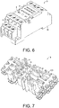
- FIG. 6 is a perspective view showing an example of the configuration of the socket 1B according to this embodiment.
- FIG. 7 is a perspective view showing an example a state in which the molded support 20B and the bar-shaped wire 2 of the socket 1B are seen from the rear side.
- the socket 1B of this embodiment is a 14-terminal type socket. Therefore, a size in the longitudinal direction of the socket 1B is the same as the length in the longitudinal of the socket 1A, while a size in the lateral direction thereof is slightly longer than the length in the lateral direction of the socket 1A.
- insulation walls 24 which insulate the plurality of bar-shaped wires 2 is formed on the molded support 20B as a molded product. Since the insulation wall 24 has a structure of a part of the molded support 20B formed of an insulating resin, it has an insulating property.
- the insulation wall 24 is formed into, for example, a flat plate. However, in the aspect of the disclosure, the insulation wall 24 is not necessarily formed into a flat plate and may be, for example, a columnar shape. As a result, as shown in FIG. 7 , the insulation wall 24 may partition all of the length of the horizontal portion 2c of the bar-shaped wire 2, but it may partition a part of the length of the horizontal portion 2c of the bar-shaped wire 2.
- the molded support 20B includes the insulation walls 24 which insulate the plurality of bar-shaped wires 2. Accordingly, it is possible to prevent short-circuiting of the bar-shaped wires 2 due to the insulation walls 24.
Landscapes
- Connections Arranged To Contact A Plurality Of Conductors (AREA)
Abstract
Description
- The disclosure relates to a socket having an external wiring connection terminal which is connected to an external wiring and an electrical device terminal connection terminal which is connected to an electrical device terminal.
- For example, Japanese Laid-open No.
2003-346939 2003-346939 - Therefore, in order to solve this problem, a method in which a connection between the external wiring connection terminal and the electrical device terminal connection terminal is made by a flat plate punched member formed of a metal plate which is punched and bent using a mold has been proposed.
- In the socket according to the related art configured to connect the terminals with a flat plate punched member formed of metal, various types of flat plate punched members having complicated shapes are required according to wiring positions. For example, shapes of the flat plate punched member may be 8 types. Therefore, the number of mold surfaces required to manufacture each of the flat plate punched materials is also increased to, for example, 16 according to the large number of types of the flat plate punched members. In addition, there is a lot of material loss due to punching, and as a result, manufacturing cost of the socket increases.
- Further, as the number of types of flat punching member increases, since it is necessary to position and assemble flat plate punching members of different kinds at correct positions, there is a problem that more time is taken for assembly, and a workload reduction effect is small, when compared with an inter-terminal connecting member made of a coated lead wire. Furthermore, if the number of types of flat punching member is large, the structure/control of the assembling apparatus becomes complicated, which is not suitable for automatic assembly.
- An aspect of the present disclosure provides a socket which allows efficient and simple connection between a connection terminal for an external wiring and a connection terminal for an electrical device terminal, and in which costs and a number of operations therefor are reduced.
- According to an aspect of the disclosure, there is provided a socket including an external wiring connection terminal which is connected to an external wiring and an electrical device terminal connection terminal which is connected to an electrical device terminal, wherein the external wiring connection terminal and the electrical device terminal connection terminal are electrically connected by a bar-shaped wire of which a shape is fixed to a predetermined shape.
- According to such a configuration, the external wiring connection terminal and the electrical device terminal connection terminal are electrically connected by the bar-shaped wire of which the shape is fixed in a predetermined shape. The bar-shaped wire of which the shape is fixed to a predetermined shape is different from a coated lead wire of which a shape is not fixed and which is easily deformed by its own weight or an external force. As a result, since the bar-shaped wire of which the shape is fixed to a predetermined shape can be formed of a bare metal wire, automatic assembly becomes possible.
- On the other hand, conventionally, when a flat plate punched member is used as an inter-terminal connection member, since the flat plate punched member has a complicated shape and many types, manufacturing cost is increased, and an effect of reducing the number of steps is also small.
- In response, in the socket according to the aspect of the disclosure, the inter-terminal connection member is formed of the bar-shaped wire of which the shape is fixed in a predetermined shape.
- For example, in the flat plate punched member, a pair of bilaterally symmetrical flat plate punched members may be required. However, when the inter-terminal connection member is formed of the bar-shaped wire, the bar-shaped wire itself can be formed into a symmetrical shape. As a result, it is possible to reduce material cost associated with the large number of types of inter-terminal connection members. Further, since the number of types of inter-terminal connection members can be reduced, it is not necessary to select the type of bar-shaped wire, and the number of steps can be reduced.
- Therefore, it is possible to provide a socket which can efficiently and easily connect between the external wiring connection terminal and the electrical device terminal connection terminal, thereby reducing the manufacturing cost and the number of steps.
- In the socket according to the aspect of the disclosure, the bar-shaped wire may be formed in a U-shape.
- Accordingly, the bar-shaped wire is formed in such a way that the shape thereof is fixed in a U shape as a predetermined shape. Therefore, for example, it is possible to connect the bar-shaped wire to the external wiring connection terminal and the electrical device terminal connection terminal by pushing both ends of the bar-shaped wire fixed in a U shape upon connection to the external wiring connection terminal and the electrical device terminal connection terminal in the inter-terminal connection member.
- As a result, even in the case of automatic assembly, the bar-shaped wire can be connected to the external wiring connection terminal and the electrical device terminal connection terminal by moving the bar-shaped wire in one direction. Further, when the inter-terminal connection member is formed into a bar-shaped wire, the number of types of inter-terminal connection member can be reduced. Therefore, the automatic assembly is facilitated, the number of steps can be reduced and the manufacturing cost can be reduced.
- In the socket according to the aspect of the disclosure, a molded product which supports the bar-shaped wire may be provided, and the molded product may have a groove or hole which fixes the bar-shaped wire in a stationary state in a direction perpendicular to a direction in which the bar-shaped wire is inserted into the molded product.
- For example, when a leg of the bar-shaped wire of which the shape is fixed in a U shape is long, there is a likelihood that the leg of the bar-shaped wire will break or bend during insertion of the bar-shaped wire. Therefore, in the socket according to the aspect of the disclosure, the molded product which supports the bar-shaped wire is provided, and the molded product has the groove or hole which fixes the bar-shaped wire in the stationary state in the direction perpendicular to the direction in which the bar-shaped wire is inserted into the molded product. Accordingly, the bar-shaped wire does not move in the direction perpendicular to the direction in which the bar-shaped wire is inserted into the molded product due to the groove or hole of the molded product.
- Therefore, it is possible to prevent the leg of the bar-shaped wire from being broken or bent when the bar-shaped wire is inserted.
- In the socket according to the aspect of the disclosure, a plurality of bar-shaped wires may be provided, and the molded product may support the bar-shaped wires to have a height difference between the bar-shaped wires in a direction in which the bar-shaped wire is inserted into the molded product.
- For example, when the plurality of bar-shaped wires are provided and the number of bar-shaped wires inside the socket increases, there is a possibility that the bar-shaped wires formed of, for example, bare wires come into contact with each other. In this case, when the plurality of bar-shaped wires are provided at the same height positions, there is a high possibility that the bar-shaped wires come into contact with each other. In response, in the socket according to the aspect of the disclosure, the molded product supports the bar-shaped wires to have a height difference between the bar-shaped wires in a direction in which the bar-shaped wire is inserted into the molded product.
- As a result, since the heights of the respective bar-shaped wires are different when the bar-shaped wires are installed and fixed, the possibility that the respective bar-shaped wires come into contact with each other can be reduced.
- In the socket according to the aspect of the disclosure, a plurality of bar-shaped wires may be provided, and the molded product may have insulation walls which insulate the plurality of bar-shaped wires.
- For example, when the plurality of bar-shaped wires are provided and the number of bar-shaped wires inside the socket increases, there is a possibility that the bar-shaped wires formed of, for example, a bare wire will come into contact with each other. Therefore, in the socket according to the aspect of the disclosure, the molded product has the insulation walls which insulate the plurality of bar-shaped wires. Therefore, it is possible to prevent short-circuiting of the bar-shaped wires with each other due to the insulation walls.
- In the socket according to the aspect of the disclosure, each of the external wiring connection terminal and the electrical device terminal connection terminal may have a bar-shaped wire end connection hole which enables electrical connection by inserting each end of the bar-shaped wire.
- Therefore, when the bar-shaped wire is inserted to connect the bar-shaped wire to the external wiring connection terminal and the electrical device terminal connection terminal, the bar-shaped wire can be connected to the external wiring connection terminal and the electrical device terminal connection terminal merely by inserting the bar-shaped wire into the respective bar-shaped wire end connection holes of the external wiring connection terminal and the electrical device terminal connection terminal.
- Therefore, it is easy to connect the bar-shaped wire to the external wiring connection terminal and the electrical device terminal connection terminal, and it is possible to reduce the number of steps.
- In the socket according to the aspect of the disclosure, a cover body having an insulating property may be provided, and the cover body may have a protrusion which fixes a position of the bar-shaped wire when the cover body is closed.
- Accordingly, when the bar-shaped wire is connected to the external wiring connection terminal and the electrical device terminal connection terminal and then covered with the cover body, the protrusion of the cover body fixes the position of the bar-shaped wire. Therefore, it is possible to prevent disconnection of the bar-shaped wire from the external wiring connection terminal and the electrical device terminal connection terminal. Further, when the bar-shaped wire is connected to the external wiring connection terminal, for example, it can be soldered to the external wiring connection terminal while the bar-shaped wire is placed on the protrusion of the cover body. As a result, it is easy to solder the bar-shaped wire to the external wiring connection terminal.
- According to the aspect of the disclosure, it is possible to provide a socket capable of efficiently and easily connecting the external wiring connection terminal with the electrical device terminal connection terminal and reducing manufacturing cost and the number of steps.
-
-
FIG. 1 is an exploded perspective view showing an example of a configuration of a socket in a first embodiment of the disclosure. -
FIG. 2 is a perspective view showing an overall configuration of the socket. -
FIG. 3 is a perspective view showing an example of the socket except for a rear cover, a molded support, and a front cover. -
FIG. 4 is a perspective view showing an example of the molded support and a bar-shaped wire of the socket seen from a rear side. -
FIG. 5 is a perspective view showing an example of the socket except for the front cover and the molded support. -
FIG. 6 is a perspective view showing an example of a configuration of a socket according to a second embodiment of the disclosure. -
FIG. 7 is a perspective view showing an example of the molded support and the bar-shaped wire of the socket seen from a rear side. - Hereinafter, an embodiment according to an aspect of the disclosure (hereinafter, also referred to as "this embodiment") will be described with reference to the drawings.
- First, an example of a situation to which the disclosure is applied will be described with reference to
FIG. 1. FIG. 1 illustrates an example of asocket 1A according to an embodiment of the disclosure and is an exploded perspective view showing a configuration of thesocket 1A. - As shown in
FIG. 1 , thesocket 1A according to an aspect of the disclosure includes an externalwiring connection terminal 3 which is connected to an external wiring, and an electrical deviceterminal connection terminal 4 which is connected to an electrical device terminal. A bar-shapedwire 2 of which a shape is fixed to a predetermined shape is electrically connected between the externalwiring connection terminal 3 and the electrical deviceterminal connection terminal 4. - According to such a configuration, the external
wiring connection terminal 3 and the electrical deviceterminal connection terminal 4 are electrically connected by the bar-shapedwire 2 of which the shape is fixed. Therefore, the bar-shapedwire 2 of which the shape is fixed is not bent, unlike a coated lead wire. As a result, the bar-shapedwire 2 with the fixed shape can be formed of a bare metal wire, and thus automatic assembly is possible. - Further, in this configuration, since an inter-terminal connection member is configured with the bar-shaped
wire 2, the bar-shapedwire 2 itself can be formed in a bilaterally symmetrical shape. As a result, it is possible to reduce manufacturing cost by reducing the number of types of inter-terminal connection members, compared with the conventional flat plate punched members. In addition, since it is not necessary to select the type of the inter-terminal connection members, it is possible to reduce the number of steps. - Accordingly, it is possible to provide a
socket 1A capable of efficiently and easily connecting the externalwiring connection terminal 3 with the electrical deviceterminal connection terminal 4 and reducing manufacturing cost and the number of steps. - The embodiment of the disclosure will be described with reference to
FIGS. 1 to 5 as follows. - An overall configuration of the
socket 1A of this embodiment will be described with reference toFIG. 2. FIG. 2 is a perspective view showing the overall configuration of thesocket 1A of this embodiment. In this embodiment, an upper side of the drawing inFIG. 2 (the side on which a relay R indicated by a dotted line is mounted) is referred to as a front side, and a lower side of the drawing inFIG. 2 is referred to as a rear side or a rear surface side. - As shown in
FIG. 2 , thesocket 1A of this embodiment has a substantially rectangular parallelepiped shape and has a total of eight externalwiring connection terminals 3, i.e., four at each of both ends thereof in a longitudinal direction. Further, eight electrical deviceterminal connection terminals 4 are provided therein, and the electrical deviceterminal connection terminals 4 are formed to be exposed through terminal insertion holes 31 formed in a front surface of afront cover 30 of thesocket 1A. As described above, thesocket 1A of this embodiment is an 8-terminal type socket. - As shown in
FIG. 2 , in this embodiment, an electrical device, for example, a relay R, is installed on a front surface of thesocket 1A. When the relay R is installed on thesocket 1A, a connection terminal (not shown) which is an electrical device terminal of the relay R is inserted into theterminal insertion hole 31 of thefront cover 30. Thus, the connection terminal of the relay R is electrically connected to the electrical deviceterminal connection terminals 4. Further, in thesocket 1A of this embodiment, it is assumed that the relay R as an electrical device is installed on thesocket 1A. However, in this embodiment of the disclosure, the number of terminals or the like is not necessarily limited thereto, and for example, an arbitrary electrical device such as a timer may also be installed on the socket. - An internal configuration of the
socket 1A will be described with reference toFIG. 1 andFIGS. 3 to 5 .FIG. 1 is an exploded perspective view showing the configuration of thesocket 1A in this embodiment.FIG. 3 is a perspective view showing an example of thesocket 1A except for arear cover 10, a moldedsupport 20A, and afront cover 30.FIG. 4 is a perspective view showing an example of the moldedsupport 20A and the bar-shapedwire 2 of thesocket 1A seen from the rear side.FIG. 5 is a perspective view showing an example of thesocket 1A except for thefront cover 30 and the moldedsupport 20A. - As shown in
FIG. 1 , thesocket 1A of this embodiment has therear cover 10 provided on the lower side and thefront cover 30 provided on the upper side. Theserear cover 10 andfront cover 30 are formed of a resin and have insulating properties. Therear cover 10 and thefront cover 30 can be integrally installed to each other by inserting aclaw 11 of therear cover 10 into aclaw hole 32 of thefront cover 30. - The molded
support 20A as a molded body, the bar-shapedwire 2 supported by the moldedsupport 20A, the externalwiring connection terminal 3, the electrical deviceterminal connection terminal 4, and awasher 5 are provided inside thesocket 1A covered by therear cover 10 and thefront cover 30. - The bar-shaped
wire 2 is a member which connects the externalwiring connection terminal 3 and the electrical deviceterminal connection terminal 4. In this embodiment, the bar-shapedwire 2 is formed of, for example, a bar-shaped bare conducting wire. A thickness of the conducting wire is, for example, about 1.5 mm. A cross section of the bar-shapedwire 2 may be a circular, elliptical or polygonal shape. In this embodiment, eight bar-shapedwires 2 are provided corresponding to the number of externalwiring connection terminals 3 and electrical deviceterminal connection terminals 4. - In this embodiment, the shape of the bar-shaped
wire 2 is fixed particularly in a predetermined shape (for example, a U-shape). That is, the bar-shapedwire 2 includes ahorizontal portion 2c and a leg which hangs down from each end of thehorizontal portion 2c. The bar-shapedwire 2 is formed of a single wire having a thickness which is not easily deformed due to its own weight or an external force at the time of assembly, rather than a flexible stranded wire. Accordingly, the U-shape of the bar-shapedwire 2 is not easily changed. Further, in the aspect of the disclosure, the bar-shapedwire 2 need not necessarily have a U-shape. - In this embodiment, for example, a length of the leg in the bar-shaped
wire 2 having the U-shape is different from each other and the bar-shapedwire 2 has along leg 2a and ashort leg 2b. A length of thehorizontal portion 2c of the bar-shapedwire 2 is different according to a connection position. Further, in this embodiment, the connection by a plurality of bar-shapedwires 2 is divided into two cases, i.e., a case in which thelong leg 2a of the bar-shapedwire 2 is connected to the externalwiring connection terminal 3 and theshort leg 2b of the bar-shapedwire 2 is connected to the electrical deviceterminal connection terminal 4, and a case in which theshort leg 2b of the bar-shapedwire 2 is connected to the externalwiring connection terminal 3 and thelong leg 2a of the bar-shapedwire 2 is connected to the electrical deviceterminal connection terminal 4. Therefore, height positions of thehorizontal portions 2c of the plurality of bar-shapedwires 2 are different from each other, and as a result, thehorizontal portions 2c of the bar-shapedwires 2 are prevented from coming into contact with each other. - As shown in
Fig. 3 , the externalwiring connection terminal 3 is connected to the external wiring (not shown) and connected to the bar-shapedwire 2. In the embodiment, as shown inFIG. 1 , four externalwiring connection terminals 3 are provided at one end of thesocket 1A in the longitudinal direction due to a step difference formed in forward and backward directions and two positions shifted in left and right directions. Additionally, four externalwiring connection terminals 3 are also provided at the other end of thesocket 1A in the longitudinal direction symmetrically with the externalwiring connection terminals 3 formed at the one end due to the step difference formed in the forward and backward directions and two positions shifted in the left and right directions. Therefore, in this embodiment, a total of eight externalwiring connection terminals 3 are provided. The number thereof corresponds to the number of connection terminals of the relay R described above. - As shown in
FIG. 1 , the externalwiring connection terminal 3 has ascrew hole 3a and a bar-shapedwire insertion hole 3b. Ascrew 6 inserted through ascrew insertion hole 33 formed in thefront cover 30 is screwed into thescrew hole 3a via thewasher 5. As a result, when an external wiring which is not shown is connected to the externalwiring connection terminal 3, the external wiring is wound around thescrew 6, and the external wiring is then fixed while placed between thescrew hole 3a and thewafer 5. - As shown in
FIG. 3 , the bar-shapedwire insertion hole 3b is a hole into which thelong leg 2a or theshort leg 2b of the bar-shapedwire 2 is inserted. Further, thelong leg 2a or theshort leg 2b of the bar-shapedwire 2 which has passed through the bar-shapedwire insertion hole 3b of the externalwiring connection terminal 3 is soldered with, for example,solder 7. - As shown in
FIG. 1 , on the front side in the electrical deviceterminal connection terminal 4, a relay connection terminal clampingplate spring portion 4a in which two plate springs are piled up is disposed to sandwich a band-shaped connection terminal (not shown) of the relay R. Further, on the rear side in the electrical deviceterminal connection terminal 4, a bar-shaped wire leg clampingplate spring portion 4b in which two plate springs are piled up is disposed to sandwich thelong leg 2a or theshort leg 2b of the bar-shapedwire 2. - Accordingly, the connection terminal of the relay R is electrically connected to the electrical device
terminal connection terminal 4 by sandwiching the connection terminal (not shown) of the relay R inserted into theterminal insertion hole 31 of thefront cover 30 between the two plate springs of the relay connection terminal clampingplate spring portion 4a. Further, the bar-shapedwire 2 is electrically connected to the electrical deviceterminal connection terminal 4 by inserting thelong legs 2a or theshort legs 2b of the bar-shapedwire 2 into the bar-shaped wire leg clampingplate spring portion 4b and sandwiching it between the two plate springs. - As shown in
FIG. 1 , the moldedsupport 20A is formed of a resin molded product having an insulating property and supports and fixes the electrical deviceterminal connection terminal 4, the bar-shapedwire 2 and the externalwiring connection terminal 3 at predetermined positions. - As shown in
FIG. 1 , eight tubularfitting portions 21 which have a square tubular shape and in which both front and rear ends are open are formed on an upper side of a center portion of the moldedsupport 20A to fit the electrical deviceterminal connection terminal 4. Therefore, since the electrical deviceterminal connection terminal 4 is inserted from the front side into the tubularfitting portion 21 and is in a fitted state, the electrical deviceterminal connection terminal 4 is held in the tubularfitting portion 21 of the moldedsupport 20A without moving in a lateral direction. A locking portion (not shown) is provided in a lower portion in the tubularfitting portion 21, and thus the electrical deviceterminal connection terminal 4 is locked to the locking portion (not shown) when the electrical deviceterminal connection terminal 4 is inserted from a front opening of the tubularfitting portion 21 and disposed in the tubularfitting portion 21. Therefore, the electrical deviceterminal connection terminal 4 does not move any more to the rear side. A front end of the electrical deviceterminal connection terminal 4 which is disposed inside the tubularfitting portion 21 is locked to thefront cover 30. Therefore, the electrical deviceterminal connection terminal 4 disposed inside the tubularfitting portion 21 does not move to the front side. - Further, as shown in
FIGS. 1 and4 , a bar-shaped wireleg holding portion 22 for holding thelong leg 2a and theshort leg 2b of the bar-shapedwire 2 stands up on the lower side of the moldedsupport 20A. Agroove 22a which fixes the bar-shapedwire 2 in a stationary state in a direction perpendicular to a direction in which the bar-shapedwire 2 is inserted into the moldedsupport 20A is formed in the bar-shaped wireleg holding portion 22. Accordingly, the bar-shapedwire 2 does not move in the direction perpendicular to the direction in which the bar-shapedwire 2 is inserted into the moldedsupport 20A. As a result, for example, when the bar-shapedwire 2 is inserted, it is possible to prevent thelong legs 2a and theshort legs 2b from being broken or bent. In addition, thegroove 22a prevents the bar-shapedwire 2 from being inclined or deformed and prevents the adjacent bar-shapedwires 2 from coming into contact with each other. In this embodiment, thegroove 22a which fixes the bar-shapedwire 2 in the stationary state in the direction perpendicular to the direction in which the bar-shapedwire 2 is inserted into the moldedsupport 20A is formed in the bar-shaped wireleg holding portion 22. However, in the aspect of the disclosure, the disclosure is not necessarily limited thereto, and a hole may be formed in the bar-shaped wireleg holding portion 22. This also makes it possible to fix the bar-shapedwire 2 in the stationary state in the direction perpendicular to the direction in which the bar-shapedwire 2 is inserted into the moldedsupport 20A. - Further, as shown in
FIG. 1 , an external wiring connectionterminal placing portion 23 which installs the externalwiring connection terminal 3 is formed at both ends of the moldedsupport 20A in the longitudinal direction. Additionally, a placingportion groove 23a extending in the front-rear direction is formed in both side surfaces of the external wiring connectionterminal placing portion 23. Therefore, since afitting protrusion 3c of the externalwiring connection terminal 3 is fitted to the placingportion groove 23a, the externalwiring connection terminal 3 can be fixed to the external wiring connectionterminal placing portion 23. - As shown in
FIG. 1 , a rearcover protruding portion 12 as a protrusion stands up on therear cover 10. Accordingly, when the bar-shapedwire 2 is connected to the externalwiring connection terminal 3 and the electrical deviceterminal connection terminal 4 and then covered with therear cover 10, for example, a tip end of the rearcover protruding portion 12 comes into contact with the bar-shapedwire 2 to fix a position of the bar-shapedwire 2. Therefore, it is possible to prevent disconnection of the bar-shapedwire 2 from the externalwiring connection terminal 3 and the electrical deviceterminal connection terminal 4. - In this embodiment, when with the
rear cover 10 is covered, the rearcover protruding portion 12 is brought into contact with the bar-shapedwire 2, for example. However, in the aspect of the disclosure, the disclosure is not limited thereto, and there may be a slightly pressed state therebetween. Also, there does not necessarily have to be contact and there may be a small gap therebetween. This is because it is thought that thelong legs 2a and theshort legs 2b of the bar-shapedwire 2 will not become disconnected from the externalwiring connection terminal 3 or the electrical deviceterminal connection terminal 4 as long as the distance therebetween is a small gap or less. As described above, therear cover 10 includes the rearcover protruding portion 12 that fixes (temporarily fixes) the positions of the plurality of bar-shapedlines 2 in a covered state. - Next, a method of assembling the
socket 1A according to this embodiment will be described. - First, as shown in
FIG. 1 , the electrical deviceterminal connection terminal 4 is inserted from the front side into the tubularfitting portion 21 of the moldedsupport 20A. Then, one of thelong leg 2a and theshort leg 2b of the bar-shapedwire 2 is inserted from the rear side of the tubularfitting portion 21. Therefore, as shown inFIG. 3 , one of thelong leg 2a and theshort leg 2b of the bar-shapedwire 2 is elastically fixed and electrically connected to the bar-shaped wire leg clampingplate spring portion 4b of the electrical deviceterminal connection terminal 4 by one of thelong leg 2a and theshort leg 2b of the bar-shapedwire 2 being clamped by the bar-shaped wire leg clampingplate spring portion 4b of the electrical deviceterminal connection terminal 4. - Further, when one of the
long leg 2a and theshort leg 2b of the bar-shapedwire 2 is inserted from the lower side of the tubularfitting portion 21, the other one of thelong leg 2a and theshort leg 2b of the bar-shapedwire 2 is adapted to pass along thegroove 22a of the bar-shaped wireleg holding portion 22 of the moldedsupport 20A, as shown inFIG. 4 . Then, as shown inFIG. 1 , the externalwiring connection terminal 3 is placed on the external wiring connectionterminal placing portion 23 of the moldedsupport 20A, and the other one of thelong leg 2a and theshort leg 2b of the bar-shapedwire 2 is adapted to pass through the bar-shapedwire insertion hole 3b of the externalwiring connection terminal 3. Thereafter, as shown inFIG. 5 , the other one of thelong leg 2a and theshort leg 2b of the bar-shapedwire 2 is soldered to the externalwiring connection terminal 3 with thesolder 7. Here, in this embodiment, when the soldering with thesolder 7 is performed, the tip end of the rearcover protruding portion 12 of therear cover 10 is brought into contact with thehorizontal portion 2c of the bar-shapedwire 2 while the other one of thelong leg 2a and theshort leg 2b of the bar-shapedwire 2 passing through the bar-shapedwire insertion hole 3b of the externalwiring connection terminal 3. Accordingly, since the bar-shapedwire 2 is placed on the rearcover protruding portion 12, the bar-shapedwire 2 is temporarily fixed. As a result, it is possible to easily perform the soldering with thesolder 7. - Next, in this state, the
front cover 30 faces therear cover 10 side, and thefront cover 30 is joined to therear cover 10 from the front side. At this time, since theclaw 11 of therear cover 10 is inserted into theclaw hole 32 of thefront cover 30, they are integrally held in a joined state. At this time, in this embodiment, the state in which the tip end of the rearcover protruding portion 12 of therear cover 10 is in contact with thehorizontal portion 2c of the bar-shapedwire 2 is maintained. As a result, it is possible to prevent the disconnection of the bar-shapedwire 2 from the externalwiring connection terminal 3 and the electrical deviceterminal connection terminal 4. - Thereafter, as shown in
FIG. 1 , an external wiring (not shown) is connected to the externalwiring connection terminal 3 with thescrew 6. Eventually, as shown inFIG. 2 , for example, the connection terminal of the relay R is inserted into theterminal insertion hole 31 of thefront cover 30 from the front side of thesocket 1A. Therefore, the relay R is electrically connected to the electrical deviceterminal connection terminal 4, and the relay R can be brought into a usable state. - When the relay R fails, since it is sufficient to remove the failed relay R from the
socket 1A and replace it with another relay R, the replacement work is also easy. - As described above, the
socket 1A of this embodiment includes the externalwiring connection terminal 3 connected to the external wiring, and the electrical deviceterminal connection terminal 4 connected to the electrical device terminal. Additionally, in thesocket 1A, the externalwiring connection terminal 3 and the electrical deviceterminal connection terminal 4 are electrically connected by the bar-shapedwire 2 of which the shape is fixed in a predetermined shape. - Accordingly, automatic assembly becomes possible. Further, in this embodiment, since the inter-terminal connection member is configured with the bar-shaped wire, the bar-shaped
wire 2 itself can be formed in a bilaterally symmetrical shape. As a result, material cost can be reduced. The number of mold surfaces can also be drastically reduced to, for example, one. - Further, since the number of types of the bar-shaped
wire 2 can be reduced, it is possible to reduce the number of steps in the case of selecting an appropriate bar-shaped wire or the like. Particularly, since common parts are used, automation of assembly can be simplified. Therefore, it is also possible to reduce the number of steps at this point. - Therefore, it is possible to provide the
socket 1A capable of efficiently and easily connecting the externalwiring connection terminal 3 with the electrical deviceterminal connection terminal 4 and reducing the manufacturing cost and the number of steps. - Further, in the
socket 1A according to this embodiment, the bar-shapedwire 2 is formed in a U-shape. Therefore, it is possible to connect the bar-shapedwire 2 to the externalwiring connection terminal 3 and the electrical deviceterminal connection terminal 4 by pushing both ends of the bar-shapedwire 2 fixed in a U shape upon connection to the externalwiring connection terminal 3 and the electrical deviceterminal connection terminal 4. As a result, even in the case of automatic assembly, the bar-shapedwire 2 can be connected to the externalwiring connection terminal 3 and the electrical deviceterminal connection terminal 4 by moving the bar-shapedwire 2 in one direction. Further, if the inter-terminal connection member is formed into the bar-shapedwire 2, the number of types of the inter-terminal connection member also decreases. For example, when the type of the bar-shapedwire 2 is changed, a length of thehorizontal portion 2c of the bar-shapedwire 2, or a length of thelong leg 2a and theshort leg 2b is changed, and the number of types is also small. Therefore, the automatic assembly is facilitated, the number of steps can be reduced, and the manufacturing cost can be reduced. - Further, in the
socket 1A according to this embodiment, the moldedsupport 20A as a molded product for supporting the bar-shapedwire 2 is provided, and the moldedsupport 20A has thegroove 22a which fixes the bar-shapedwire 2 in the stationary state in the direction perpendicular to the direction in which the bar-shapedwire 2 is inserted into the moldedsupport 20A. Therefore, the bar-shapedwire 2 does not move in the direction perpendicular to the direction in which the bar-shapedwire 2 is inserted into the moldedsupport 20A due to thegroove 22a of the moldedsupport 20A. - Therefore, it is possible to prevent the legs of the bar-shaped
wire 2 from being broken or bent when the bar-shapedwire 2 is inserted. - Further, in the
socket 1A according to this embodiment, the plurality of bar-shapedwires 2 are provided, and the moldedsupport 20A supports the bar-shapedwire 2 to have a height difference between the bar-shapedwires 2 in the direction in which the bar-shapedwire 2 is inserted into the moldedsupport 20A. For example, a height position of thehorizontal portion 2c of at least one bar-shapedwire 2 and a height position of thehorizontal portion 2c of at least one of other bar-shapedwires 2 are different from each other. As a result, since the height positions of the plurality of bar-shapedwires 2 are different from each other when the bar-shapedwires 2 are installed and fixed, it is possible to reduce the possibility that the respective bar-shapedwires 2 come into contact with each other. Also, the plurality of bar-shapedwires 2 having different height positions may be disposed to intersect each other. The plurality of bar-shapedwires 2 having the same height positions of thehorizontal portions 2c may be disposed. - Further, in the
socket 1A according to this embodiment, each of the externalwiring connection terminal 3 and the electrical deviceterminal connection terminal 4 includes the bar-shapedwire insertion hole 3b, and a bar-shaped wire leg clampingplate spring portion 4b as a bar-shaped wire end connection hole which enables electrical connection by inserting each end of the bar-shapedwire 2. Therefore, the bar-shapedwire 2 can be connected to the externalwiring connection terminal 3 and the electrical deviceterminal connection terminal 4 merely by inserting the bar-shapedwire 2 into the bar-shapedwire insertion hole 3b and the bar-shaped wire leg clampingplate spring portion 4b. - Therefore, it is easy to connect the bar-shaped
wire 2 to the externalwiring connection terminal 3 and the electrical deviceterminal connection terminal 4, and it is possible to reduce the number of steps. - Further, in the
socket 1A according to this embodiment, therear cover 10 as a cover body having an insulating property is provided, and therear cover 10 has a rearcover protruding portion 12 as a protrusion which fixes the position of the bar-shapedwire 2 by coming into contact with or pressing or having a gap to thebar wire 2 when it is closed. - Accordingly, when the bar-shaped
wire 2 is connected to the externalwiring connection terminal 3 and the electrical deviceterminal connection terminal 4 and then covered with therear cover 10, the rearcover protruding portion 12 fixes the position of the bar-shapedwire 2 while coming into contact with, or pressing, or having a gap to the bar-shapedwire 2. Therefore, it is possible to prevent the disconnection of the bar-shapedwire 2 from the externalwiring connection terminal 3. - Another embodiment of the disclosure will be described with reference to
FIGS. 6 and 7 as follows. Configurations other than those described in this embodiment are the same as those in the first embodiment. Further, for convenience of explanation, members having the same functions as the members shown in the drawings of the first embodiment are designated by the same reference numerals, and description thereof will be omitted. - A
socket 1B of this embodiment is different from thesocket 1A according to the first embodiment in that insulation walls for insulating the plurality of bar-shapedwires 2 are provided at a moldedsupport 20B as a molded product. - The configuration of the
socket 1B of this embodiment will be described with reference toFIGS. 6 and 7. FIG. 6 is a perspective view showing an example of the configuration of thesocket 1B according to this embodiment.FIG. 7 is a perspective view showing an example a state in which the moldedsupport 20B and the bar-shapedwire 2 of thesocket 1B are seen from the rear side. - As shown in
FIG. 6 , in thesocket 1B of this embodiment, 14 terminal insertion holes 31 are provided in the upper surface of thefront cover 30. As a result, 14 electrical deviceterminal connection terminals 4 and 14 externalwiring connection terminals 3 are provided. Therefore, thesocket 1B of this embodiment is a 14-terminal type socket. Therefore, a size in the longitudinal direction of thesocket 1B is the same as the length in the longitudinal of thesocket 1A, while a size in the lateral direction thereof is slightly longer than the length in the lateral direction of thesocket 1A. - As described above, when the number of terminals of the electrical device
terminal connection terminal 4 and the externalwiring connection terminal 3 increases, density of the bar-shapedwires 2 inside thesocket 1A also increases, and the possibility that thehorizontal portions 2c of the bar-shapedwires 2 come into contact with each other increases. - Therefore, in the
socket 1B according to this embodiment, as shown inFIG. 7 ,insulation walls 24 which insulate the plurality of bar-shapedwires 2 is formed on the moldedsupport 20B as a molded product. Since theinsulation wall 24 has a structure of a part of the moldedsupport 20B formed of an insulating resin, it has an insulating property. Theinsulation wall 24 is formed into, for example, a flat plate. However, in the aspect of the disclosure, theinsulation wall 24 is not necessarily formed into a flat plate and may be, for example, a columnar shape. As a result, as shown inFIG. 7 , theinsulation wall 24 may partition all of the length of thehorizontal portion 2c of the bar-shapedwire 2, but it may partition a part of the length of thehorizontal portion 2c of the bar-shapedwire 2. - As described above, in the
socket 1B according to this embodiment, the moldedsupport 20B includes theinsulation walls 24 which insulate the plurality of bar-shapedwires 2. Accordingly, it is possible to prevent short-circuiting of the bar-shapedwires 2 due to theinsulation walls 24. -
- 1A, 1B Socket
- 2 Bar-shaped wire
- 2a Long leg
- 2b Short leg
- 2c Horizontal portion
- 3 External wiring connection terminal
- 3a Screw hole
- 4 Electrical device terminal connection terminal
- 4a Relay connection terminal clamping plate spring portion
- 4b Bar-shaped wire leg clamping plate spring portion
- 5 Washer
- 6 Screw
- 7 Solder
- 10 Rear cover (cover body)
- 20A, 20B Molded support (molded body)
- 21 Tubular fitting portion
- 22 Bar-shaped wire leg holding portion
- 23 External wiring connection terminal placing portion
- 23a Placing portion groove
- 24 Insulation wall
- 30 Front cover
- 31 Terminal insertion hole
Claims (7)
- A socket (1A, 1B) comprising an external wiring connection terminal (3) which is connected to an external wiring and an electrical device terminal connection terminal (4) which is connected to an electrical device terminal, characterized in that,
the external wiring connection terminal (3) and the electrical device terminal connection terminal (4) are electrically connected by a bar-shaped wire (2) of which a shape is fixed to a predetermined shape. - The socket (1A, 1B) according to claim 1, wherein the bar-shaped wire (2) is formed in a U-shape.
- The socket (1A, 1B) according to claim 2, wherein a molded product (20A, 20B) which supports the bar-shaped wire (2) is provided, and the molded product (20A, 20B) has a groove (22a) or hole which fixes the bar-shaped wire (2) in a stationary state in a direction perpendicular to a direction in which the bar-shaped wire (2) is inserted into the molded product (20A, 20B).
- The socket (1A, 1B) according to claim 3, wherein a plurality of bar-shaped wires (2) are provided, and the molded product (20A, 20B) supports the bar-shaped wires (2) to have a height difference between the bar-shaped wires (2) in a direction in which the bar-shaped wire (2) is inserted into the molded product (20A, 20B).
- The socket (1A, 1B) according to claim 3, wherein a plurality of bar-shaped wires (2) are provided, and the molded product (20A, 20B) has insulation walls (24) which insulate the plurality of bar-shaped wires (2).
- The socket (1A, 1B) according to any one of claims 1 to 5, wherein each of the external wiring connection terminal (3) and the electrical device terminal connection terminal (4) has a bar-shaped wire end connection hole (4b) which enables electrical connection by inserting each end of the bar-shaped wire (2).
- The socket (1A, 1B) according to any one of claims 1 to 6, wherein a cover body (10) having an insulating property is provided, and the cover body (10) has a protrusion (12) which fixes a position of the bar-shaped wire (2) when the cover body (10) is closed.
Applications Claiming Priority (1)
| Application Number | Priority Date | Filing Date | Title |
|---|---|---|---|
| JP2017204717A JP2019079653A (en) | 2017-10-23 | 2017-10-23 | socket |
Publications (1)
| Publication Number | Publication Date |
|---|---|
| EP3474382A1 true EP3474382A1 (en) | 2019-04-24 |
Family
ID=63556208
Family Applications (1)
| Application Number | Title | Priority Date | Filing Date |
|---|---|---|---|
| EP18193449.8A Withdrawn EP3474382A1 (en) | 2017-10-23 | 2018-09-10 | Socket |
Country Status (4)
| Country | Link |
|---|---|
| US (1) | US20190123458A1 (en) |
| EP (1) | EP3474382A1 (en) |
| JP (1) | JP2019079653A (en) |
| CN (1) | CN109698414A (en) |
Families Citing this family (3)
| Publication number | Priority date | Publication date | Assignee | Title |
|---|---|---|---|---|
| JP6950672B2 (en) * | 2018-12-26 | 2021-10-13 | オムロン株式会社 | Terminal block |
| CN111755849B (en) * | 2020-07-01 | 2025-09-26 | 周口市海鑫精密工业有限公司 | An electrical connector |
| CN216487927U (en) | 2021-12-17 | 2022-05-10 | 温州华亚电气有限公司 | Novel earth leakage protection socket of intelligence |
Citations (5)
| Publication number | Priority date | Publication date | Assignee | Title |
|---|---|---|---|---|
| US4851967A (en) * | 1987-04-01 | 1989-07-25 | Krone Aktiengesellschaft | Distribution bank for communication cables |
| JP2003346939A (en) | 2002-05-27 | 2003-12-05 | Omron Corp | Socket device and lead wire connecting method for the socket device |
| US20090149074A1 (en) * | 2007-12-10 | 2009-06-11 | Hans-Josef Koellmann | Connecting module |
| EP2393160A1 (en) * | 2010-06-02 | 2011-12-07 | Weidmüller Interface GmbH & Co. KG | Shunt clamp in a stacked design |
| DE102013022222A1 (en) * | 2013-12-18 | 2015-06-18 | Phoenix Contact Gmbh & Co. Kg | Connection device and manufacturing method thereof |
Family Cites Families (1)
| Publication number | Priority date | Publication date | Assignee | Title |
|---|---|---|---|---|
| EP2256867B1 (en) * | 2009-05-11 | 2017-10-04 | CommScope Connectivity Spain, S.L. | Electrical Connector |
-
2017
- 2017-10-23 JP JP2017204717A patent/JP2019079653A/en not_active Abandoned
-
2018
- 2018-09-10 EP EP18193449.8A patent/EP3474382A1/en not_active Withdrawn
- 2018-09-11 CN CN201811054194.8A patent/CN109698414A/en active Pending
- 2018-09-17 US US16/133,641 patent/US20190123458A1/en not_active Abandoned
Patent Citations (5)
| Publication number | Priority date | Publication date | Assignee | Title |
|---|---|---|---|---|
| US4851967A (en) * | 1987-04-01 | 1989-07-25 | Krone Aktiengesellschaft | Distribution bank for communication cables |
| JP2003346939A (en) | 2002-05-27 | 2003-12-05 | Omron Corp | Socket device and lead wire connecting method for the socket device |
| US20090149074A1 (en) * | 2007-12-10 | 2009-06-11 | Hans-Josef Koellmann | Connecting module |
| EP2393160A1 (en) * | 2010-06-02 | 2011-12-07 | Weidmüller Interface GmbH & Co. KG | Shunt clamp in a stacked design |
| DE102013022222A1 (en) * | 2013-12-18 | 2015-06-18 | Phoenix Contact Gmbh & Co. Kg | Connection device and manufacturing method thereof |
Also Published As
| Publication number | Publication date |
|---|---|
| US20190123458A1 (en) | 2019-04-25 |
| CN109698414A (en) | 2019-04-30 |
| JP2019079653A (en) | 2019-05-23 |
Similar Documents
| Publication | Publication Date | Title |
|---|---|---|
| US8449338B2 (en) | Electrical connector | |
| US7874870B1 (en) | Coaxial cable connector with a connection terminal having a resilient tongue section | |
| US9806442B2 (en) | Plug connection device | |
| US10468792B2 (en) | Terminal block | |
| KR20150127550A (en) | Electronic device mounting apparatus | |
| WO2010146525A1 (en) | Low cost clamp for connection of electric wires or cables on printed circuits | |
| US20190123458A1 (en) | Socket | |
| US4087150A (en) | Quick connect wiring system for breadboard circuits | |
| CN110416786B (en) | Conductive terminal, coupler and motor comprising same and assembly method of coupler | |
| JP2016096021A (en) | Printed circuit board with circuit board terminal and electrical junction box using the same | |
| US9203170B2 (en) | Pin header | |
| CN109586121B (en) | Plug device and power distribution system | |
| EP3644446B1 (en) | Conductive terminal and connector assembly | |
| JP2017107801A (en) | Wiring module | |
| JP6486961B2 (en) | Electrical junction box and board connector | |
| JP5662674B2 (en) | Connector and connector assembly method | |
| US20120287591A1 (en) | Connection member | |
| US6375518B2 (en) | Connecting method of connectors | |
| US11695224B1 (en) | Lever connector for electrical conductors | |
| US3932017A (en) | Electrical terminal assembly and terminal therefor | |
| US9614296B2 (en) | Conductive terminal for electrically connecting a circuit conductor and another connection terminal | |
| EP4322343B1 (en) | Assembly method for a printed circuit board electrical connector | |
| JP2016152214A (en) | Board straight insertion wire and board straight insertion connector using the same | |
| CN210326247U (en) | Coupling and electric machine comprising said coupling | |
| CN209844004U (en) | Coupling and electric machine comprising said coupling |
Legal Events
| Date | Code | Title | Description |
|---|---|---|---|
| PUAI | Public reference made under article 153(3) epc to a published international application that has entered the european phase |
Free format text: ORIGINAL CODE: 0009012 |
|
| STAA | Information on the status of an ep patent application or granted ep patent |
Free format text: STATUS: REQUEST FOR EXAMINATION WAS MADE |
|
| 17P | Request for examination filed |
Effective date: 20180910 |
|
| AK | Designated contracting states |
Kind code of ref document: A1 Designated state(s): AL AT BE BG CH CY CZ DE DK EE ES FI FR GB GR HR HU IE IS IT LI LT LU LV MC MK MT NL NO PL PT RO RS SE SI SK SM TR |
|
| AX | Request for extension of the european patent |
Extension state: BA ME |
|
| RBV | Designated contracting states (corrected) |
Designated state(s): AL AT BE BG CH CY CZ DE DK EE ES FI FR GB GR HR HU IE IS IT LI LT LU LV MC MK MT NL NO PL PT RO RS SE SI SK SM TR |
|
| STAA | Information on the status of an ep patent application or granted ep patent |
Free format text: STATUS: THE APPLICATION HAS BEEN WITHDRAWN |
|
| 18W | Application withdrawn |
Effective date: 20200311 |