EP3474372B1 - Antenna for wearable radio system and associated method of making - Google Patents
Antenna for wearable radio system and associated method of making Download PDFInfo
- Publication number
- EP3474372B1 EP3474372B1 EP18201207.0A EP18201207A EP3474372B1 EP 3474372 B1 EP3474372 B1 EP 3474372B1 EP 18201207 A EP18201207 A EP 18201207A EP 3474372 B1 EP3474372 B1 EP 3474372B1
- Authority
- EP
- European Patent Office
- Prior art keywords
- antenna
- ground plane
- dielectric strip
- elongate dielectric
- radiating element
- Prior art date
- Legal status (The legal status is an assumption and is not a legal conclusion. Google has not performed a legal analysis and makes no representation as to the accuracy of the status listed.)
- Active
Links
- 238000004519 manufacturing process Methods 0.000 title description 4
- 230000005540 biological transmission Effects 0.000 claims description 12
- 238000007493 shaping process Methods 0.000 claims description 11
- 230000009977 dual effect Effects 0.000 description 7
- 230000008878 coupling Effects 0.000 description 6
- 238000010168 coupling process Methods 0.000 description 6
- 238000005859 coupling reaction Methods 0.000 description 6
- 238000010586 diagram Methods 0.000 description 5
- 230000005855 radiation Effects 0.000 description 4
- 230000000694 effects Effects 0.000 description 3
- 230000007613 environmental effect Effects 0.000 description 3
- 238000000034 method Methods 0.000 description 3
- 238000010521 absorption reaction Methods 0.000 description 2
- 230000008901 benefit Effects 0.000 description 2
- 230000007246 mechanism Effects 0.000 description 2
- 238000012986 modification Methods 0.000 description 2
- 230000004048 modification Effects 0.000 description 2
- 239000004593 Epoxy Substances 0.000 description 1
- 238000013459 approach Methods 0.000 description 1
- 239000004744 fabric Substances 0.000 description 1
- 239000006260 foam Substances 0.000 description 1
- 230000003116 impacting effect Effects 0.000 description 1
- 230000006698 induction Effects 0.000 description 1
- 230000010354 integration Effects 0.000 description 1
- 238000002955 isolation Methods 0.000 description 1
- 239000000463 material Substances 0.000 description 1
- 230000003071 parasitic effect Effects 0.000 description 1
- 229920003023 plastic Polymers 0.000 description 1
- 239000004033 plastic Substances 0.000 description 1
- 230000008569 process Effects 0.000 description 1
- 230000001681 protective effect Effects 0.000 description 1
- 238000005096 rolling process Methods 0.000 description 1
- 239000000758 substrate Substances 0.000 description 1
Images


Classifications
-
- H—ELECTRICITY
- H01—ELECTRIC ELEMENTS
- H01Q—ANTENNAS, i.e. RADIO AERIALS
- H01Q1/00—Details of, or arrangements associated with, antennas
- H01Q1/27—Adaptation for use in or on movable bodies
- H01Q1/273—Adaptation for carrying or wearing by persons or animals
-
- H—ELECTRICITY
- H01—ELECTRIC ELEMENTS
- H01Q—ANTENNAS, i.e. RADIO AERIALS
- H01Q1/00—Details of, or arrangements associated with, antennas
- H01Q1/08—Means for collapsing antennas or parts thereof
- H01Q1/085—Flexible aerials; Whip aerials with a resilient base
-
- H—ELECTRICITY
- H01—ELECTRIC ELEMENTS
- H01Q—ANTENNAS, i.e. RADIO AERIALS
- H01Q1/00—Details of, or arrangements associated with, antennas
- H01Q1/48—Earthing means; Earth screens; Counterpoises
-
- H—ELECTRICITY
- H01—ELECTRIC ELEMENTS
- H01Q—ANTENNAS, i.e. RADIO AERIALS
- H01Q13/00—Waveguide horns or mouths; Slot antennas; Leaky-waveguide antennas; Equivalent structures causing radiation along the transmission path of a guided wave
- H01Q13/10—Resonant slot antennas
- H01Q13/106—Microstrip slot antennas
-
- H—ELECTRICITY
- H01—ELECTRIC ELEMENTS
- H01Q—ANTENNAS, i.e. RADIO AERIALS
- H01Q21/00—Antenna arrays or systems
- H01Q21/30—Combinations of separate antenna units operating in different wavebands and connected to a common feeder system
-
- H—ELECTRICITY
- H01—ELECTRIC ELEMENTS
- H01Q—ANTENNAS, i.e. RADIO AERIALS
- H01Q5/00—Arrangements for simultaneous operation of antennas on two or more different wavebands, e.g. dual-band or multi-band arrangements
- H01Q5/30—Arrangements for providing operation on different wavebands
- H01Q5/307—Individual or coupled radiating elements, each element being fed in an unspecified way
- H01Q5/314—Individual or coupled radiating elements, each element being fed in an unspecified way using frequency dependent circuits or components, e.g. trap circuits or capacitors
- H01Q5/321—Individual or coupled radiating elements, each element being fed in an unspecified way using frequency dependent circuits or components, e.g. trap circuits or capacitors within a radiating element or between connected radiating elements
-
- H—ELECTRICITY
- H01—ELECTRIC ELEMENTS
- H01Q—ANTENNAS, i.e. RADIO AERIALS
- H01Q9/00—Electrically-short antennas having dimensions not more than twice the operating wavelength and consisting of conductive active radiating elements
- H01Q9/04—Resonant antennas
- H01Q9/0407—Substantially flat resonant element parallel to ground plane, e.g. patch antenna
-
- H—ELECTRICITY
- H01—ELECTRIC ELEMENTS
- H01Q—ANTENNAS, i.e. RADIO AERIALS
- H01Q9/00—Electrically-short antennas having dimensions not more than twice the operating wavelength and consisting of conductive active radiating elements
- H01Q9/04—Resonant antennas
- H01Q9/30—Resonant antennas with feed to end of elongated active element, e.g. unipole
- H01Q9/40—Element having extended radiating surface
-
- H—ELECTRICITY
- H04—ELECTRIC COMMUNICATION TECHNIQUE
- H04B—TRANSMISSION
- H04B1/00—Details of transmission systems, not covered by a single one of groups H04B3/00 - H04B13/00; Details of transmission systems not characterised by the medium used for transmission
- H04B1/38—Transceivers, i.e. devices in which transmitter and receiver form a structural unit and in which at least one part is used for functions of transmitting and receiving
- H04B1/3827—Portable transceivers
- H04B1/385—Transceivers carried on the body, e.g. in helmets
Definitions
- the present invention relates to antennas, and more particularly, to a wearable radio system and antenna and a method of making the antenna.
- High-performance radio transceivers used by military, first responders, emergency personnel and similar users have become increasingly more powerful and include multiple frequency bands, however, antenna designs have not advanced accordingly. Some progress has been made in recent years to reduce the size and number of antennas by increasing their flexibility and providing support for multiple frequency bands. Of particular interest to military, first responders and other emergency personnel are the ergonomic and performance innovations accompanying the area of body-worn antennas. Body worn antennas can be covert and low profile or protrude above and over the head.
- Body worn antennas can be convert and low profile, or overt and protrude above the head.
- body-worn antennas are worn close to the body and when they do not extend above the head, they are less likely to hinder the agility and movement of the user or impede rapid access to the radio transceiver and other essential devices. If a body-worn antenna is flush mounted on the body, however, it may decrease radio transceiver performance. Sometimes a foam layer is placed on the antenna between the body. This improves performance, but this approach often makes the antenna awkward and inflexible for use.
- Current body-worn antennas may have other drawbacks, including a cumbersome connection process, a tendency to lose signal strength if too close to the body, and an awkward antenna mounting system.
- This antenna should maintain a low-profile while reducing signal absorption and shadow effects without impacting the signal strength when the antenna is worn close to the body. Additionally, the antenna should not hinder the user's ability to readily access the radio transceivers, for example, for attaching accessories such as handsets, terminals, and other accessories.
- Document US2008074340 discloses a dual-frequency high-gain antenna, which includes: a diplexer loop portion disposed at the center of the antenna substrate for receiving a feed signal; two single-frequency radiation units, symmetrically connected to two sides of the diplexer loop portion for radiating a radio-frequency signal corresponding to a first frequency value of the feed signal; and two dual-frequency radiation units, respectively connected to each single-frequency radiation portion for radiating radio-frequency signals corresponding to the first frequency value and a second frequency value of the feed signal.
- Document WO0163699 discloses a transmit/receive antenna that selectively operates to transmit or receive at one or more of a plurality of different frequencies in the MHz range.
- a planar transmission line diplexer or multiplexer that is selected from the group microstrip multiplexer diplexer/multiplexer and stripline diplexer/multiplexer connects an input/output port to a plurality of antenna ports that are physically spaced from each other and from the input/output port.
- One antenna element is connected to each of the antenna ports.
- the transmission line diplexer/multiplexer includes a plurality of individual microstrip/stripline elements that have a characteristic impedance and a length that are selected such that the transmission line diplexer/multiplexer automatically provides a matched impedance path between a given antenna element and the input/output port when an antenna-matching frequency is received by the given antenna element or when the antenna matching frequency is applied to the input/output port.
- the transmission line diplexer/multiplexer automatically provides a very mismatched impedance path between all others of the antenna elements and the input/output port.
- Document GB2539327 discloses a body-wearable antenna with at least two directional antenna elements mountable in an equi-spaced distributed array around the user's body, wherein antenna elements operate in phase to deliver a combined omnidirectional performance radiating away from the user's body.
- Antenna elements are securely mounted within radomes and worn on the front and back of the user.
- the antenna elements can be planar inverted F-shaped (PIFA) antennas and the radomes may be made from hard plastics.
- the PIFA antennas may have dual band capability by providing a slot in the radiating top plate of the PIFA and wide band frequency operation may be achieved by the use of parasitic resonators.
- Each antenna element is connected via a connector to a coaxial cable which electrically connects the antenna elements to a 2:1 zero degree phase power divider which is connected to a power source held within equipment casing.
- An antenna includes an elongate dielectric strip having opposing top and bottom sides.
- a first conductive pattern defines a first radiating element for a first frequency range on the top side of said elongate dielectric strip.
- a second conductive pattern defines a second radiating element for a second frequency range on the top side of said elongate dielectric strip. The second frequency range is different than the first frequency range.
- a diplexer circuit is on said elongate dielectric strip between said first and second radiating elements and coupled to said first and second radiating elements.
- a third conductive pattern defines a shared ground plane for the first and second radiating elements on the bottom side of said elongate dielectric strip.
- the shared ground plane comprises longitudinally adjacent first and second ground plane portions a filter coupled between the first and second ground plane portions so that the first and second ground plane portions function as a ground plane for the first radiating element and the second ground plane portion functions as a ground plane for the second radiating element.
- the first ground plane portion may have at least one beam pattern shaping slot therein.
- a fourth conductive pattern may define respective first and second transmission lines coupling the diplexer circuit to the respective first and second radiating elements on the first side of the elongate dielectric strip.
- the shared ground plane may comprise respective first and second slots aligned with the first and second transmission lines, respectively.
- the first radiating element may extend to a first end of the elongate dielectric strip and the second radiating element may extend to a second end of the elongate dielectric strip.
- the elongate dielectric strip is a bistable elongate dielectric strip.
- the first frequency range is between 225 to 450 MHz
- the second frequency range is between 1300 to 2600 MHz.
- a wearable radio system may comprise a wearable vest and a radio transceiver carried by the wearable vest, and the antenna is carried by the wearable vest and coupled to the radio transceiver.
- a method of making an antenna comprises forming a first conductive pattern defining a first radiating element for a first frequency range on a first side of an elongate dielectric strip and forming a second conductive pattern defining a second radiating element for a second frequency range on the first side of the elongate dielectric strip, the second frequency range being different than the first frequency range.
- the method further comprises forming a diplexer circuit on the elongate dielectric strip between the first and second radiating elements and coupled thereto and forming a third conductive pattern defining a shared ground plane for the first and second radiating elements on a second side of the elongate dielectric strip.
- a prior art dual band whip antenna is indicated generally at 20 in FIGS. 1 and 2 and is carried on the back of a user and coupled to a conventional radio transceiver 22.
- This type of dual band whip antenna 20 is large and cumbersome and extends above the head, making it burdensome during essential activities, for example, ingress through windows.
- this antenna 20 includes first and second radiating elements 24, 26.
- the first radiating element 24 operates in the UHF band and the second radiating element 26 operates in the L-band.
- the antenna 20 includes a feed circuit 28 at an isolation gap 30 as illustrated in FIG. 2 .
- the antenna indicated generally at 40 overcomes the drawbacks of not only prior art whip antennas such as shown in FIGS. 1 and 2 , but also more conventional, body-worn antennas.
- the antenna 40 includes a feed 41 into a shared ground plane 42 for first and second radiating elements 44, 46 to provide a dual band antenna useful, for example, in both the UHF band and L-band.
- the antenna 40 is lightweight, flexible and has a reduced size because the shared ground plane 42 improves performance, and addresses the pattern distortion issue that may occur with shorter dual band antennas.
- Conductive pattern such as on the dielectric strip, may refer also to printed traces and coupling can be a direct connection, or in some examples, even wireless.
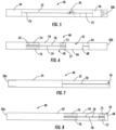
- the antenna 40 includes an elongate dielectric strip 50 as best shown in FIG. 4 , having opposing first and second sides 52 , 54 with an enlarged portion of the first side shown in FIGS. 5 and 7 , and an enlarged portion of the second side shown in FIGS. 6 and 8 .
- a first conductive pattern defines the first radiating element 44 for a first frequency range on the first side 52 of the elongate dielectric strip 50 and a second conductive pattern defines the second radiating element 46 for a second frequency range on the first side 52 of the elongate dielectric strip.
- the first and second conductive patterns in an example can each be formed as a printed trace.
- the first radiating element 44 extends to a first end 50a of the elongate dielectric strip 50 and the second radiating element 46 extends to the second end 50b of the elongate dielectric strip 50.
- the second frequency range has a different frequency range than the first frequency range.
- the first frequency range is within the UHF band and is preferably between 225 to 450 MHz and the second frequency range is in the L-band and is preferably between 1300 to 2600 MHz.
- a diplexer circuit indicated generally at 56 is operative as a matching circuit and is on the first side 52 of the elongate dielectric strip 50 between the first and second radiating elements 44, 46 and coupled thereto as also shown in detail in FIG. 5 .
- the diplexer circuit 56 includes a number of circuit traces 58 and circuit components 60 ( FIG. 9 ) for antenna operation in the selected frequency bands.
- a third conductive pattern that can be formed as a printed trace defines the shared ground plane 42 for the first and second radiating elements 44, 46 on the second side 54 of the elongate dielectric strip 50 as best shown in the enlarged view of the second side in FIGS. 6 and 8 .
- the shared ground plane 42 includes longitudinally adjacent first and second ground plane portions 62 , 64 ( FIG. 6 ) and a filter 66 coupled between the first and second ground plane portions.
- the first and second ground plane portions 62 , 64 function as a ground plane for the first radiating element 44 and the second ground plane portion 64 functions as a ground plane for the second radiating element 46 and the combined longitudinal length is shorter than the two individual lengths.
- the filter 66 may be formed as an isolating inductor that connects to the third conductive pattern defining the shared ground plane 42 on the second side 54 of the elongate dielectric strip 50 to create an electromagnetic boundary and permit those frequencies in the first frequency range, such as UHF frequencies, to view first and second ground plane portions 62 , 64 as one electromagnetic structure, but block those frequencies in the second range of frequencies, such as the L-band frequency, from passing through the filter 66 , therefore limiting the size of that second ground plane portion 64.
- the filter 66 may be formed as an isolating inductor, and in one example, as a five (5) nanoHenry inductor, although the inductance value may vary depending on the operative frequencies for both the first and second frequency ranges, the size of the respective first and second radiating elements 44 , 46, and the overall size of the elongate dielectric strip 50 in both width and length.
- the third conductive pattern defining the shared ground plane 42 of the first and second radiating elements 44, 46 may be patterned and operate using a selected induction value to form the filter 66 , and the actual selected inductance is a function of the desired frequencies. In the illustrated embodiment shown in FIGS.
- a rectangular section 68 of glass-reinforced epoxy laminate is placed over a section of the second side 54 near the shared ground plane 42 to add some rigidity to the area of the antenna 40 where the diplexer circuit 56 is located on the first side 52.
- a fourth conductive pattern such as formed as a printed trace is best shown in FIG. 4 and the enlarged plan views of FIGS. 5 and 7 and defines respective first and second transmission lines 70 , 72 coupling the diplexer circuit 56 to the respective first and second radiating elements 44, 46 on the first side 52 of the elongate dielectric strip 50.
- the first ground plane portion 62 has at least one beam pattern shaping slot, and in the illustrated example, includes respective first and second beam pattern shaping slots 74 , 75 , 76 , 77 aligned with the first and second transmission lines 70, 72, respectively ( FIGS. 6 and 8 ).
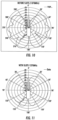
- the first and second beam pattern shaping slots 74, 75, 76, 77 reduce the coupling of radiated fields that create a distorted antenna pattern shape as shown in the graph of FIG. 10 , which is an example of an antenna beam pattern when no beam pattern shaping slot is formed in the first ground plane portion 62.
- the first and second beam pattern shaping slots 74, 75, 76, 77 reduce the coupling of the radiated fields from the first and second radiating element 46 and are positioned behind the first transmission line 70.
- An optimized L-band antenna pattern when the beam pattern shaping slots 74, 75, 76, 77 are used is shown in the antenna beam pattern graph of FIG. 11 , which shows a better beam pattern in all elevation directions.
- FIGS. 6 and 8 also show a characteristic impedance slot 78 extending in the center between the first and second beam pattern shaping slots 74, 75, 76, 77.
- this characteristic impedance slot 78 operates as a transmission line slot and includes shorting bars 79 formed transverse across a portion of the longitudinal length of the characteristic impedance slot. The shorting bars 79 operate with the characteristic impedance slot 78 so there will not be any potential difference that gives rise to other radiating modes.
- the antenna 40 is incorporated with a wearable radio system illustrated generally at 80 and includes a wearable vest 82 that is worn by the user, for example, associated with the military, a police search and rescue, an emergency unit, or a first responder.
- a radio transceiver 84 is carried by the wearable vest 82 and the antenna 40 is carried by the wearable vest and coupled to the radio transceiver.
- the elongate dielectric strip 50 is contained within a protective sheath, for example, a thick cloth housing to provide protection.
- the antenna 40 may be attached to coupling elements 86 of the vest or by other attachment mechanisms, for example, mobile straps.
- the antenna 40 is in an extended position with the second radiating element 46 corresponding to the L-band operating at the second frequency band extended upward. It does not extend beyond the head of the user.
- the antenna 40 is formed with an elongate dielectric strip 50 that is bistable to allow the antenna to be pressed forward or "slapped" into a retracted position as shown in FIG. 13 where the top portion of the antenna conforms to the shoulder of the user.
- the antenna can be used in both positions.
- the second radiating element 46 operating in the second frequency band such as the L-band can still be as high as possible with minimal signal blockage.
- Part of the elongate dielectric strip 50 may include a bistable spring material that will coil around the shoulder when slapped against the shoulder as shown in FIG. 13 .
- the wearable vest 82 supporting the antenna 82 will provide the necessary distance between the user's body and antenna so that the specific absorption rate (SAR) in the body is reduced while antenna gain is increased as shown in the graph of FIG. 14 , illustrating the SAR and antenna gain for a body-worn antenna.
- SAR specific absorption rate
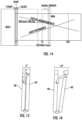
- FIGS. 15 and 16 it is possible to incorporate the antenna 40' with a hinge mount mechanism 90' as shown in FIGS. 15 and 16 , which allows the antenna to be pivoted a distance sufficient to minimize SAR and maximize gain as shown in FIG. 16 .
- a method of making the antenna 40 includes forming a first conductive pattern defining a first radiating element 44 for a first frequency range on a first side 52 of the elongate dielectric strip 50 and forming a second conductive pattern defining a second radiating element 46 for a second frequency range on the first side of the elongate dielectric strip, the second frequency range being different than the first frequency range.
- the method includes forming a diplexer circuit 56 on the elongate dielectric strip 50 between the first and second radiating elements 44 , 46 and coupled thereto and forming a third conductive pattern defining a shared ground plane 42 for the first and second radiating elements on a second side 54 of the elongate dielectric strip.
Description
- The present invention relates to antennas, and more particularly, to a wearable radio system and antenna and a method of making the antenna.
- High-performance radio transceivers used by military, first responders, emergency personnel and similar users have become increasingly more powerful and include multiple frequency bands, however, antenna designs have not advanced accordingly. Some progress has been made in recent years to reduce the size and number of antennas by increasing their flexibility and providing support for multiple frequency bands. Of particular interest to military, first responders and other emergency personnel are the ergonomic and performance innovations accompanying the area of body-worn antennas. Body worn antennas can be covert and low profile or protrude above and over the head.
- Body worn antennas can be convert and low profile, or overt and protrude above the head. In addition, body-worn antennas are worn close to the body and when they do not extend above the head, they are less likely to hinder the agility and movement of the user or impede rapid access to the radio transceiver and other essential devices. If a body-worn antenna is flush mounted on the body, however, it may decrease radio transceiver performance. Sometimes a foam layer is placed on the antenna between the body. This improves performance, but this approach often makes the antenna awkward and inflexible for use. Current body-worn antennas may have other drawbacks, including a cumbersome connection process, a tendency to lose signal strength if too close to the body, and an awkward antenna mounting system.
- There are also performance and reliability issues because these body-worn antennas often were not designed for integration with the high-performance radio transceivers now being used by military, first responders, emergency personnel and similar users. For example, some body-worn antennas have limited bandwidth to only a single band, which is inappropriate for a multiband radio transceiver. Also, current body-worn antennas are often large and inflexible and impede movement. Users of such body-worn antennas often create their own "fixes" such as rolling up and down the antenna, often 10 to 20 times a day, or affixing it under a shoulder pad so it does not interfere with other activities. Some users forgo use of conventional body-worn antennas and instead use a single band whip antenna, which is often suitable for a single frequency but not multiple bands of frequencies. They also may be suitable for many lower frequency communications, such as in the UHF-band, but not suitable for higher frequency communications, such as in the L-band.
- This produces a need for an antenna that may be used with a wearable radio system and provide flexibility, ease of connection and consistency of performance across at least two frequency bands without significant signal loss. This antenna should maintain a low-profile while reducing signal absorption and shadow effects without impacting the signal strength when the antenna is worn close to the body. Additionally, the antenna should not hinder the user's ability to readily access the radio transceivers, for example, for attaching accessories such as handsets, terminals, and other accessories.
- Document
US2008074340 discloses a dual-frequency high-gain antenna, which includes: a diplexer loop portion disposed at the center of the antenna substrate for receiving a feed signal; two single-frequency radiation units, symmetrically connected to two sides of the diplexer loop portion for radiating a radio-frequency signal corresponding to a first frequency value of the feed signal; and two dual-frequency radiation units, respectively connected to each single-frequency radiation portion for radiating radio-frequency signals corresponding to the first frequency value and a second frequency value of the feed signal. - Document
WO0163699 - Document
GB2539327 - An antenna includes an elongate dielectric strip having opposing top and bottom sides. A first conductive pattern defines a first radiating element for a first frequency range on the top side of said elongate dielectric strip. A second conductive pattern defines a second radiating element for a second frequency range on the top side of said elongate dielectric strip. The second frequency range is different than the first frequency range. A diplexer circuit is on said elongate dielectric strip between said first and second radiating elements and coupled to said first and second radiating elements. A third conductive pattern defines a shared ground plane for the first and second radiating elements on the bottom side of said elongate dielectric strip.
- The shared ground plane comprises longitudinally adjacent first and second ground plane portions a filter coupled between the first and second ground plane portions so that the first and second ground plane portions function as a ground plane for the first radiating element and the second ground plane portion functions as a ground plane for the second radiating element.
- The first ground plane portion may have at least one beam pattern shaping slot therein. A fourth conductive pattern may define respective first and second transmission lines coupling the diplexer circuit to the respective first and second radiating elements on the first side of the elongate dielectric strip. The shared ground plane may comprise respective first and second slots aligned with the first and second transmission lines, respectively.
- The first radiating element may extend to a first end of the elongate dielectric strip and the second radiating element may extend to a second end of the elongate dielectric strip. The elongate dielectric strip is a bistable elongate dielectric strip. In an example, the first frequency range is between 225 to 450 MHz, and the second frequency range is between 1300 to 2600 MHz.
- In yet another example, a wearable radio system may comprise a wearable vest and a radio transceiver carried by the wearable vest, and the antenna is carried by the wearable vest and coupled to the radio transceiver.
- In yet another example, a method of making an antenna comprises forming a first conductive pattern defining a first radiating element for a first frequency range on a first side of an elongate dielectric strip and forming a second conductive pattern defining a second radiating element for a second frequency range on the first side of the elongate dielectric strip, the second frequency range being different than the first frequency range. The method further comprises forming a diplexer circuit on the elongate dielectric strip between the first and second radiating elements and coupled thereto and forming a third conductive pattern defining a shared ground plane for the first and second radiating elements on a second side of the elongate dielectric strip.
- Other objects, features and advantages of the present invention will become apparent from the detailed description of the invention which follows, when considered in light of the accompanying drawings in which:
-
FIG. 1 is a fragmentary environmental view of a user wearing a radio system and prior art dual band whip style antenna. -
FIG. 2 is a schematic diagram of the prior art dual band whip antenna shown inFIG. 1 . -
FIG. 3 is a fragmentary block diagram of the antenna having a shared ground plane for first and second radiating elements in accordance with a non-limiting example. -
FIG. 4 is a top plan view of the first side of the dielectric strip used in the antenna ofFIG. 3 . -
FIG. 5 is an enlarged top plan view of the first side of the dielectric strip in the antenna ofFIG. 4 . -
FIG. 6 is an enlarged bottom plan view of the second side of the dielectric strip in the antenna ofFIG. 4 . -
FIG. 7 is another enlarged top plan view of the first side of the dielectric strip in the antenna ofFIG. 4 . -
FIG. 8 is another enlarged bottom plan view of the second side of the dielectric strip in the antenna ofFIG. 4 . -
FIG. 9 is an enlarged top plan view of the diplexer circuit in the antenna ofFIG. 4 . -
FIG. 10 is a graph showing an antenna pattern when no beam pattern shaping slots are incorporated in the antenna ofFIG. 4 . -
FIG. 11 is a graph showing an optimized antenna pattern when beam pattern shaping slots are incorporated into the antenna ofFIG. 4 . -
FIG. 12 is a fragmentary environmental view of a wearable radio system and the antenna ofFIG. 4 in an extended position. -
FIG. 13 is another fragmentary environmental view of the wearable radio system and the antenna ofFIG. 4 in a retracted position. -
FIG. 14 is a graph showing an example of the radiation hazard of a body-worn antenna relative to distance from a body. -
FIG. 15 is a fragmentary side elevation diagram of a hinge mount for the antenna in a retracted position ofFIGS. 12 and 13 . -
FIG. 16 is another fragmentary side elevation diagram of the hinge mount for the antenna in an extended position ofFIGS. 12 and 13 . - The present description is made with reference to the accompanying drawings, in which exemplary embodiments are shown. However, many different embodiments may be used, and thus, the description should not be construed as limited to the particular embodiments set forth herein. Rather, these embodiments are provided so that this disclosure will be thorough and complete. Like numbers refer to like elements throughout, and prime notation is used to indicate similar elements in different embodiments.
- A prior art dual band whip antenna is indicated generally at 20 in
FIGS. 1 and 2 and is carried on the back of a user and coupled to aconventional radio transceiver 22. This type of dualband whip antenna 20 is large and cumbersome and extends above the head, making it burdensome during essential activities, for example, ingress through windows. In an example, thisantenna 20 includes first andsecond radiating elements first radiating element 24 operates in the UHF band and thesecond radiating element 26 operates in the L-band. Theantenna 20 includes afeed circuit 28 at anisolation gap 30 as illustrated inFIG. 2 . - Referring now to
FIGS. 3-9 , the antenna indicated generally at 40, in accordance with a non-limiting example, overcomes the drawbacks of not only prior art whip antennas such as shown inFIGS. 1 and 2 , but also more conventional, body-worn antennas. As best shown in the block diagram example ofFIG. 3 , theantenna 40 includes afeed 41 into a sharedground plane 42 for first andsecond radiating elements antenna 40 is lightweight, flexible and has a reduced size because the sharedground plane 42 improves performance, and addresses the pattern distortion issue that may occur with shorter dual band antennas. Throughout this description, different terms are used. Conductive pattern, such as on the dielectric strip, may refer also to printed traces and coupling can be a direct connection, or in some examples, even wireless. - The
antenna 40 includes an elongatedielectric strip 50 as best shown inFIG. 4 , having opposing first andsecond sides FIGS. 5 and 7 , and an enlarged portion of the second side shown inFIGS. 6 and 8 . A first conductive pattern defines thefirst radiating element 44 for a first frequency range on thefirst side 52 of the elongatedielectric strip 50 and a second conductive pattern defines thesecond radiating element 46 for a second frequency range on thefirst side 52 of the elongate dielectric strip. The first and second conductive patterns in an example can each be formed as a printed trace. Thefirst radiating element 44 extends to afirst end 50a of the elongatedielectric strip 50 and thesecond radiating element 46 extends to thesecond end 50b of the elongatedielectric strip 50. The second frequency range has a different frequency range than the first frequency range. Although different frequency ranges may be employed, in one example, the first frequency range is within the UHF band and is preferably between 225 to 450 MHz and the second frequency range is in the L-band and is preferably between 1300 to 2600 MHz. A diplexer circuit indicated generally at 56 is operative as a matching circuit and is on thefirst side 52 of the elongatedielectric strip 50 between the first andsecond radiating elements FIG. 5 . Thediplexer circuit 56 includes a number of circuit traces 58 and circuit components 60 (FIG. 9 ) for antenna operation in the selected frequency bands. A third conductive pattern that can be formed as a printed trace defines the sharedground plane 42 for the first andsecond radiating elements second side 54 of the elongatedielectric strip 50 as best shown in the enlarged view of the second side inFIGS. 6 and 8 . - The shared
ground plane 42 includes longitudinally adjacent first and secondground plane portions 62, 64 (FIG. 6 ) and afilter 66 coupled between the first and second ground plane portions. The first and secondground plane portions first radiating element 44 and the secondground plane portion 64 functions as a ground plane for thesecond radiating element 46 and the combined longitudinal length is shorter than the two individual lengths. In an example, thefilter 66 may be formed as an isolating inductor that connects to the third conductive pattern defining the sharedground plane 42 on thesecond side 54 of the elongatedielectric strip 50 to create an electromagnetic boundary and permit those frequencies in the first frequency range, such as UHF frequencies, to view first and secondground plane portions filter 66, therefore limiting the size of that secondground plane portion 64. - The
filter 66 may be formed as an isolating inductor, and in one example, as a five (5) nanoHenry inductor, although the inductance value may vary depending on the operative frequencies for both the first and second frequency ranges, the size of the respective first andsecond radiating elements dielectric strip 50 in both width and length. The third conductive pattern defining the sharedground plane 42 of the first andsecond radiating elements filter 66, and the actual selected inductance is a function of the desired frequencies. In the illustrated embodiment shown inFIGS. 6 and 8 , arectangular section 68 of glass-reinforced epoxy laminate is placed over a section of thesecond side 54 near the sharedground plane 42 to add some rigidity to the area of theantenna 40 where thediplexer circuit 56 is located on thefirst side 52. - A fourth conductive pattern such as formed as a printed trace is best shown in
FIG. 4 and the enlarged plan views ofFIGS. 5 and 7 and defines respective first andsecond transmission lines diplexer circuit 56 to the respective first andsecond radiating elements first side 52 of the elongatedielectric strip 50. The firstground plane portion 62 has at least one beam pattern shaping slot, and in the illustrated example, includes respective first and second beampattern shaping slots second transmission lines FIGS. 6 and 8 ). The first and second beampattern shaping slots FIG. 10 , which is an example of an antenna beam pattern when no beam pattern shaping slot is formed in the firstground plane portion 62. The first and second beampattern shaping slots second radiating element 46 and are positioned behind thefirst transmission line 70. An optimized L-band antenna pattern when the beampattern shaping slots FIG. 11 , which shows a better beam pattern in all elevation directions. -
FIGS. 6 and 8 also show acharacteristic impedance slot 78 extending in the center between the first and second beampattern shaping slots FIG. 8 , thischaracteristic impedance slot 78 operates as a transmission line slot and includes shortingbars 79 formed transverse across a portion of the longitudinal length of the characteristic impedance slot. The shorting bars 79 operate with thecharacteristic impedance slot 78 so there will not be any potential difference that gives rise to other radiating modes. - Referring now to
FIGS. 12 and 13 , theantenna 40 is incorporated with a wearable radio system illustrated generally at 80 and includes awearable vest 82 that is worn by the user, for example, associated with the military, a police search and rescue, an emergency unit, or a first responder. Aradio transceiver 84 is carried by thewearable vest 82 and theantenna 40 is carried by the wearable vest and coupled to the radio transceiver. The elongatedielectric strip 50 is contained within a protective sheath, for example, a thick cloth housing to provide protection. Theantenna 40 may be attached tocoupling elements 86 of the vest or by other attachment mechanisms, for example, mobile straps. - As shown in
FIG. 12 , theantenna 40 is in an extended position with thesecond radiating element 46 corresponding to the L-band operating at the second frequency band extended upward. It does not extend beyond the head of the user. Theantenna 40 is formed with an elongatedielectric strip 50 that is bistable to allow the antenna to be pressed forward or "slapped" into a retracted position as shown inFIG. 13 where the top portion of the antenna conforms to the shoulder of the user. The antenna can be used in both positions. When it is extended as inFIG. 12 , thesecond radiating element 46 operating in the second frequency band such as the L-band can still be as high as possible with minimal signal blockage. Part of the elongatedielectric strip 50 may include a bistable spring material that will coil around the shoulder when slapped against the shoulder as shown inFIG. 13 . - Usually, the
wearable vest 82 supporting theantenna 82 will provide the necessary distance between the user's body and antenna so that the specific absorption rate (SAR) in the body is reduced while antenna gain is increased as shown in the graph ofFIG. 14 , illustrating the SAR and antenna gain for a body-worn antenna. However, if a thin vest is used and the SAR is unsafe, it is possible to incorporate the antenna 40' with a hinge mount mechanism 90' as shown inFIGS. 15 and 16 , which allows the antenna to be pivoted a distance sufficient to minimize SAR and maximize gain as shown inFIG. 16 . - A method of making the
antenna 40 includes forming a first conductive pattern defining afirst radiating element 44 for a first frequency range on afirst side 52 of the elongatedielectric strip 50 and forming a second conductive pattern defining asecond radiating element 46 for a second frequency range on the first side of the elongate dielectric strip, the second frequency range being different than the first frequency range. The method includes forming adiplexer circuit 56 on the elongatedielectric strip 50 between the first andsecond radiating elements ground plane 42 for the first and second radiating elements on asecond side 54 of the elongate dielectric strip. - Many modifications and other embodiments of the invention will come to the mind of one skilled in the art having the benefit of the teachings presented in the foregoing descriptions and the associated drawings. Therefore, it is understood that the invention is not to be limited to the specific embodiments disclosed, and that modifications and embodiments are intended to be included within the scope of the appended claims.
Claims (6)
- An antenna (40) comprising:an elongate dielectric strip (50) having opposing top and bottom sides (52, 54);a first conductive pattern defining a first radiating element (44) for a first frequency range on the top side of said elongate dielectric strip (50);a second conductive pattern defining a second radiating element (46) for a second frequency range on the top side of said elongate dielectric strip (50), the second frequency range being different than the first frequency range;a diplexer circuit (56) on said elongate dielectric strip (50) between said first and second radiating elements (44, 46) and coupled to said first and second radiating elements (44, 46); anda third conductive pattern defining a shared ground plane (42) for the first and second radiating elements (44, 46) on the bottom side of said elongate dielectric strip (50);whereinsaid shared ground plane (42) comprises longitudinally adjacent first and second ground plane portions (62, 64); and characterized by further comprising a filter (66) coupled between the first and second ground plane portions so that the first and second ground plane portions (62, 64) function as a ground plane for the first radiating element (44) and the second ground plane portion (64) functions as a ground plane for the second radiating element (46), wherein the elongate dielectric strip (50) is bistable.
- The antenna (40) according to Claim 1 wherein said first ground plane portion (62) has at least one beam pattern shaping slot therein.
- The antenna (40) according to Claim 1 further comprising a fourth conductive pattern defining respective first and second transmission lines (70, 72) adapted to couple the diplexer circuit (56) to the respective first and second radiating elements (44, 46) on the top side of said elongate dielectric strip (50).
- The antenna (40) according to Claim 3 wherein said shared ground plane (42) comprises respective first and second slots therein aligned with said first and second transmission lines (70, 72), respectively.
- The antenna (40) according to Claim 1 wherein said first radiating element (44) extends to a first end of said elongate dielectric strip (50); and wherein said second radiating element (46) extends to a second end of said elongate dielectric strip (50).
- A wearable radio system (80) comprising:a wearable vest (82);a radio transceiver (84) carried by said wearable vest (82); andan antenna (40) according to any of claims 1 - 5 carried by said wearable vest (82) and coupled to said radio transceiver (84).
Applications Claiming Priority (1)
| Application Number | Priority Date | Filing Date | Title |
|---|---|---|---|
| US15/787,746 US10868358B2 (en) | 2017-10-19 | 2017-10-19 | Antenna for wearable radio system and associated method of making |
Publications (2)
| Publication Number | Publication Date |
|---|---|
| EP3474372A1 EP3474372A1 (en) | 2019-04-24 |
| EP3474372B1 true EP3474372B1 (en) | 2023-05-03 |
Family
ID=63914862
Family Applications (1)
| Application Number | Title | Priority Date | Filing Date |
|---|---|---|---|
| EP18201207.0A Active EP3474372B1 (en) | 2017-10-19 | 2018-10-18 | Antenna for wearable radio system and associated method of making |
Country Status (2)
| Country | Link |
|---|---|
| US (1) | US10868358B2 (en) |
| EP (1) | EP3474372B1 (en) |
Families Citing this family (9)
| Publication number | Priority date | Publication date | Assignee | Title |
|---|---|---|---|---|
| US9078162B2 (en) * | 2013-03-15 | 2015-07-07 | DGS Global Systems, Inc. | Systems, methods, and devices for electronic spectrum management |
| US10237770B2 (en) | 2013-03-15 | 2019-03-19 | DGS Global Systems, Inc. | Systems, methods, and devices having databases and automated reports for electronic spectrum management |
| US10231206B2 (en) * | 2013-03-15 | 2019-03-12 | DGS Global Systems, Inc. | Systems, methods, and devices for electronic spectrum management for identifying signal-emitting devices |
| US10700794B2 (en) | 2017-01-23 | 2020-06-30 | Digital Global Systems, Inc. | Systems, methods, and devices for automatic signal detection based on power distribution by frequency over time within an electromagnetic spectrum |
| US10459020B2 (en) | 2017-01-23 | 2019-10-29 | DGS Global Systems, Inc. | Systems, methods, and devices for automatic signal detection based on power distribution by frequency over time within a spectrum |
| US10529241B2 (en) | 2017-01-23 | 2020-01-07 | Digital Global Systems, Inc. | Unmanned vehicle recognition and threat management |
| USD876256S1 (en) * | 2018-05-14 | 2020-02-25 | Padres L.P. | Scanner attachment |
| US10860823B2 (en) | 2018-05-14 | 2020-12-08 | Padres L.P. | Scan crutch |
| US10943461B2 (en) | 2018-08-24 | 2021-03-09 | Digital Global Systems, Inc. | Systems, methods, and devices for automatic signal detection based on power distribution by frequency over time |
Family Cites Families (34)
| Publication number | Priority date | Publication date | Assignee | Title |
|---|---|---|---|---|
| US2576128A (en) * | 1948-04-03 | 1951-11-27 | Motorola Inc | Man-pack antenna |
| US3523296A (en) * | 1967-04-25 | 1970-08-04 | Hellige & Co Gmbh F | Portable antenna |
| US3902118A (en) * | 1974-04-04 | 1975-08-26 | Us Army | Body-coupled portable transmitter |
| US4041394A (en) * | 1976-07-06 | 1977-08-09 | River Range Developments Limited | Radio control transmitter |
| US6256938B1 (en) | 1987-04-30 | 2001-07-10 | Rolatube Technology Limited | Elongate hollow element |
| US4847629A (en) * | 1988-08-03 | 1989-07-11 | Alliance Research Corporation | Retractable cellular antenna |
| FR2759498B1 (en) * | 1997-02-07 | 1999-08-27 | Thomson Csf | VARIABLE GEOMETRY ANTENNA |
| US6179666B1 (en) * | 1999-02-05 | 2001-01-30 | Michael L. Osborn | Two-way radio accessory quick connect and extension cord |
| US6307525B1 (en) | 2000-02-25 | 2001-10-23 | Centurion Wireless Technologies, Inc. | Multiband flat panel antenna providing automatic routing between a plurality of antenna elements and an input/output port |
| US6590540B1 (en) * | 2002-01-31 | 2003-07-08 | The United States Of America As Represented By The Secretary Of The Navy | Ultra-broadband antenna incorporated into a garment |
| US20030155389A1 (en) | 2002-02-20 | 2003-08-21 | Swartzentruber Vincent Dale | Slap on watch |
| US20040036655A1 (en) * | 2002-08-22 | 2004-02-26 | Robert Sainati | Multi-layer antenna structure |
| US6765539B1 (en) * | 2003-01-24 | 2004-07-20 | Input Output Precise Corporation | Planar multiple band omni radiation pattern antenna |
| US6919850B2 (en) * | 2003-04-28 | 2005-07-19 | Motorola Inc. | Body worn antenna |
| US6940462B2 (en) * | 2003-09-19 | 2005-09-06 | Harris Corporation | Broadband dipole antenna to be worn by a user and associated methods |
| US7064729B2 (en) * | 2003-10-01 | 2006-06-20 | Arc Wireless Solutions, Inc. | Omni-dualband antenna and system |
| US7053851B1 (en) | 2003-10-21 | 2006-05-30 | R.A. Miller Industries, Inc. | Dual dipole antenna with isolation circuit |
| US7274339B2 (en) * | 2005-09-16 | 2007-09-25 | Smartant Telecom Co., Ltd. | Dual-band multi-mode array antenna |
| US7369094B2 (en) * | 2006-09-26 | 2008-05-06 | Smartant Telecom Co., Ltd. | Dual-frequency high-gain antenna |
| US7969369B2 (en) * | 2007-07-11 | 2011-06-28 | Harris Corporation | Body-worn antenna fastening device and method |
| US7755553B2 (en) * | 2007-08-20 | 2010-07-13 | Harris Corporation | Multiband antenna system for body-worn and dismount applications |
| US7755559B2 (en) * | 2008-12-09 | 2010-07-13 | Mobile Mark, Inc. | Dual-band omnidirectional antenna |
| US8810463B2 (en) * | 2011-05-06 | 2014-08-19 | Jeffrey B. Kirkham | Antenna mount |
| US8425243B2 (en) * | 2011-07-11 | 2013-04-23 | Apple Inc. | Magnetically activated connector port cover |
| US9287630B2 (en) | 2012-12-03 | 2016-03-15 | Intel Corporation | Dual-band folded meta-inspired antenna with user equipment embedded wideband characteristics |
| US9197294B2 (en) * | 2013-03-12 | 2015-11-24 | Tyco Fire & Security Gmbh | Transponder tag with improved tolerance to presence of near-field loading material |
| US9209514B2 (en) | 2013-08-09 | 2015-12-08 | Motorola Solutions, Inc. | Body-worn antenna |
| US9343800B2 (en) * | 2013-08-09 | 2016-05-17 | Motorola Solutions, Inc. | Flexible mounting apparatus for mounting an antenna |
| GB2535353B (en) | 2013-09-09 | 2017-02-22 | Rtl Mat Ltd | Antenna assembly comprising slit-tubular mast |
| US9786990B2 (en) * | 2014-02-24 | 2017-10-10 | R.A. Miller Industries, Inc. | Integrated multiband antenna |
| US9653785B2 (en) | 2015-01-23 | 2017-05-16 | Sony Corporation | Antennas for body-worn wireless electronic devices |
| US20160345695A1 (en) | 2015-06-01 | 2016-12-01 | Scooch, LLC | Bistable spring stand and housing for a handheld device |
| GB201510487D0 (en) | 2015-06-12 | 2015-11-18 | Secr Defence | Body-wearable antenna defence |
| WO2017164727A1 (en) * | 2016-03-22 | 2017-09-28 | Motorola Solutions, Inc. | Portable, wearable radio comprising a modular harness |
-
2017
- 2017-10-19 US US15/787,746 patent/US10868358B2/en active Active
-
2018
- 2018-10-18 EP EP18201207.0A patent/EP3474372B1/en active Active
Also Published As
| Publication number | Publication date |
|---|---|
| US10868358B2 (en) | 2020-12-15 |
| EP3474372A1 (en) | 2019-04-24 |
| US20190123428A1 (en) | 2019-04-25 |
Similar Documents
| Publication | Publication Date | Title |
|---|---|---|
| EP3474372B1 (en) | Antenna for wearable radio system and associated method of making | |
| EP0829112B1 (en) | Multiple band printed monopole antenna | |
| EP0829113B1 (en) | Multiple band printed monopole antenna | |
| US5539414A (en) | Folded dipole microstrip antenna | |
| EP2546922B1 (en) | Mobile communication device and antenna device | |
| US6380903B1 (en) | Antenna systems including internal planar inverted-F antennas coupled with retractable antennas and wireless communicators incorporating same | |
| EP1493204B1 (en) | Multi-band planar antenna | |
| WO1996038882A9 (en) | Multiple band printed monopole antenna | |
| US20050128151A1 (en) | Internal multi-band antenna with multiple layers | |
| CN104051841B (en) | Enhanced efficient 3G/4G/LTE antennas, equipment is with and related methods | |
| TWI644479B (en) | Multiple antenna apparatus | |
| WO2001052353A2 (en) | Low cost compact omni-directional printed antenna | |
| JP2007166599A (en) | Mobile communication terminal with plural antennas mounted therein | |
| EP2533359B1 (en) | Arrangement | |
| US8433269B2 (en) | Compact satellite antenna | |
| CN110970709A (en) | Antenna structure and wireless communication device with same | |
| CN108336480B (en) | Antenna system and mobile terminal | |
| Malar et al. | Novel aperture coupled fractal antenna for Internet of wearable things (IoWT) | |
| CN102340056B (en) | Multiband antenna | |
| US10374311B2 (en) | Antenna for a portable communication device | |
| EP2037532A1 (en) | Flat dual-band antenna | |
| KR101076749B1 (en) | Antena for wireless usb dongle and wireless usb dongle using the same of | |
| KR101200097B1 (en) | Multi-band antenna for mobile unit | |
| Malar et al. | Measurement: Sensors | |
| CN117957476A (en) | Electronic device with millimeter wave antenna |
Legal Events
| Date | Code | Title | Description |
|---|---|---|---|
| PUAI | Public reference made under article 153(3) epc to a published international application that has entered the european phase |
Free format text: ORIGINAL CODE: 0009012 |
|
| STAA | Information on the status of an ep patent application or granted ep patent |
Free format text: STATUS: REQUEST FOR EXAMINATION WAS MADE |
|
| 17P | Request for examination filed |
Effective date: 20181018 |
|
| AK | Designated contracting states |
Kind code of ref document: A1 Designated state(s): AL AT BE BG CH CY CZ DE DK EE ES FI FR GB GR HR HU IE IS IT LI LT LU LV MC MK MT NL NO PL PT RO RS SE SI SK SM TR |
|
| AX | Request for extension of the european patent |
Extension state: BA ME |
|
| RAP1 | Party data changed (applicant data changed or rights of an application transferred) |
Owner name: HARRIS GLOBAL COMMUNICATIONS, INC. |
|
| STAA | Information on the status of an ep patent application or granted ep patent |
Free format text: STATUS: EXAMINATION IS IN PROGRESS |
|
| 17Q | First examination report despatched |
Effective date: 20210126 |
|
| STAA | Information on the status of an ep patent application or granted ep patent |
Free format text: STATUS: EXAMINATION IS IN PROGRESS |
|
| GRAP | Despatch of communication of intention to grant a patent |
Free format text: ORIGINAL CODE: EPIDOSNIGR1 |
|
| STAA | Information on the status of an ep patent application or granted ep patent |
Free format text: STATUS: GRANT OF PATENT IS INTENDED |
|
| INTG | Intention to grant announced |
Effective date: 20221206 |
|
| GRAS | Grant fee paid |
Free format text: ORIGINAL CODE: EPIDOSNIGR3 |
|
| GRAA | (expected) grant |
Free format text: ORIGINAL CODE: 0009210 |
|
| STAA | Information on the status of an ep patent application or granted ep patent |
Free format text: STATUS: THE PATENT HAS BEEN GRANTED |
|
| AK | Designated contracting states |
Kind code of ref document: B1 Designated state(s): AL AT BE BG CH CY CZ DE DK EE ES FI FR GB GR HR HU IE IS IT LI LT LU LV MC MK MT NL NO PL PT RO RS SE SI SK SM TR |
|
| REG | Reference to a national code |
Ref country code: GB Ref legal event code: FG4D |
|
| REG | Reference to a national code |
Ref country code: AT Ref legal event code: REF Ref document number: 1565471 Country of ref document: AT Kind code of ref document: T Effective date: 20230515 Ref country code: CH Ref legal event code: EP |
|
| REG | Reference to a national code |
Ref country code: DE Ref legal event code: R096 Ref document number: 602018049137 Country of ref document: DE |
|
| REG | Reference to a national code |
Ref country code: IE Ref legal event code: FG4D |
|
| P01 | Opt-out of the competence of the unified patent court (upc) registered |
Effective date: 20230530 |
|
| REG | Reference to a national code |
Ref country code: LT Ref legal event code: MG9D |
|
| REG | Reference to a national code |
Ref country code: NL Ref legal event code: MP Effective date: 20230503 |
|
| REG | Reference to a national code |
Ref country code: AT Ref legal event code: MK05 Ref document number: 1565471 Country of ref document: AT Kind code of ref document: T Effective date: 20230503 |
|
| PG25 | Lapsed in a contracting state [announced via postgrant information from national office to epo] |
Ref country code: SE Free format text: LAPSE BECAUSE OF FAILURE TO SUBMIT A TRANSLATION OF THE DESCRIPTION OR TO PAY THE FEE WITHIN THE PRESCRIBED TIME-LIMIT Effective date: 20230503 Ref country code: PT Free format text: LAPSE BECAUSE OF FAILURE TO SUBMIT A TRANSLATION OF THE DESCRIPTION OR TO PAY THE FEE WITHIN THE PRESCRIBED TIME-LIMIT Effective date: 20230904 Ref country code: NO Free format text: LAPSE BECAUSE OF FAILURE TO SUBMIT A TRANSLATION OF THE DESCRIPTION OR TO PAY THE FEE WITHIN THE PRESCRIBED TIME-LIMIT Effective date: 20230803 Ref country code: NL Free format text: LAPSE BECAUSE OF FAILURE TO SUBMIT A TRANSLATION OF THE DESCRIPTION OR TO PAY THE FEE WITHIN THE PRESCRIBED TIME-LIMIT Effective date: 20230503 Ref country code: ES Free format text: LAPSE BECAUSE OF FAILURE TO SUBMIT A TRANSLATION OF THE DESCRIPTION OR TO PAY THE FEE WITHIN THE PRESCRIBED TIME-LIMIT Effective date: 20230503 Ref country code: AT Free format text: LAPSE BECAUSE OF FAILURE TO SUBMIT A TRANSLATION OF THE DESCRIPTION OR TO PAY THE FEE WITHIN THE PRESCRIBED TIME-LIMIT Effective date: 20230503 |
|
| PG25 | Lapsed in a contracting state [announced via postgrant information from national office to epo] |
Ref country code: RS Free format text: LAPSE BECAUSE OF FAILURE TO SUBMIT A TRANSLATION OF THE DESCRIPTION OR TO PAY THE FEE WITHIN THE PRESCRIBED TIME-LIMIT Effective date: 20230503 Ref country code: PL Free format text: LAPSE BECAUSE OF FAILURE TO SUBMIT A TRANSLATION OF THE DESCRIPTION OR TO PAY THE FEE WITHIN THE PRESCRIBED TIME-LIMIT Effective date: 20230503 Ref country code: LV Free format text: LAPSE BECAUSE OF FAILURE TO SUBMIT A TRANSLATION OF THE DESCRIPTION OR TO PAY THE FEE WITHIN THE PRESCRIBED TIME-LIMIT Effective date: 20230503 Ref country code: LT Free format text: LAPSE BECAUSE OF FAILURE TO SUBMIT A TRANSLATION OF THE DESCRIPTION OR TO PAY THE FEE WITHIN THE PRESCRIBED TIME-LIMIT Effective date: 20230503 Ref country code: IS Free format text: LAPSE BECAUSE OF FAILURE TO SUBMIT A TRANSLATION OF THE DESCRIPTION OR TO PAY THE FEE WITHIN THE PRESCRIBED TIME-LIMIT Effective date: 20230903 Ref country code: HR Free format text: LAPSE BECAUSE OF FAILURE TO SUBMIT A TRANSLATION OF THE DESCRIPTION OR TO PAY THE FEE WITHIN THE PRESCRIBED TIME-LIMIT Effective date: 20230503 Ref country code: GR Free format text: LAPSE BECAUSE OF FAILURE TO SUBMIT A TRANSLATION OF THE DESCRIPTION OR TO PAY THE FEE WITHIN THE PRESCRIBED TIME-LIMIT Effective date: 20230804 |
|
| PG25 | Lapsed in a contracting state [announced via postgrant information from national office to epo] |
Ref country code: FI Free format text: LAPSE BECAUSE OF FAILURE TO SUBMIT A TRANSLATION OF THE DESCRIPTION OR TO PAY THE FEE WITHIN THE PRESCRIBED TIME-LIMIT Effective date: 20230503 |
|
| PG25 | Lapsed in a contracting state [announced via postgrant information from national office to epo] |
Ref country code: SK Free format text: LAPSE BECAUSE OF FAILURE TO SUBMIT A TRANSLATION OF THE DESCRIPTION OR TO PAY THE FEE WITHIN THE PRESCRIBED TIME-LIMIT Effective date: 20230503 |
|
| PGFP | Annual fee paid to national office [announced via postgrant information from national office to epo] |
Ref country code: GB Payment date: 20231027 Year of fee payment: 6 |
|
| PG25 | Lapsed in a contracting state [announced via postgrant information from national office to epo] |
Ref country code: SM Free format text: LAPSE BECAUSE OF FAILURE TO SUBMIT A TRANSLATION OF THE DESCRIPTION OR TO PAY THE FEE WITHIN THE PRESCRIBED TIME-LIMIT Effective date: 20230503 Ref country code: SK Free format text: LAPSE BECAUSE OF FAILURE TO SUBMIT A TRANSLATION OF THE DESCRIPTION OR TO PAY THE FEE WITHIN THE PRESCRIBED TIME-LIMIT Effective date: 20230503 Ref country code: RO Free format text: LAPSE BECAUSE OF FAILURE TO SUBMIT A TRANSLATION OF THE DESCRIPTION OR TO PAY THE FEE WITHIN THE PRESCRIBED TIME-LIMIT Effective date: 20230503 Ref country code: EE Free format text: LAPSE BECAUSE OF FAILURE TO SUBMIT A TRANSLATION OF THE DESCRIPTION OR TO PAY THE FEE WITHIN THE PRESCRIBED TIME-LIMIT Effective date: 20230503 Ref country code: DK Free format text: LAPSE BECAUSE OF FAILURE TO SUBMIT A TRANSLATION OF THE DESCRIPTION OR TO PAY THE FEE WITHIN THE PRESCRIBED TIME-LIMIT Effective date: 20230503 Ref country code: CZ Free format text: LAPSE BECAUSE OF FAILURE TO SUBMIT A TRANSLATION OF THE DESCRIPTION OR TO PAY THE FEE WITHIN THE PRESCRIBED TIME-LIMIT Effective date: 20230503 |
|
| PGFP | Annual fee paid to national office [announced via postgrant information from national office to epo] |
Ref country code: IT Payment date: 20231023 Year of fee payment: 6 Ref country code: FR Payment date: 20231025 Year of fee payment: 6 Ref country code: DE Payment date: 20231027 Year of fee payment: 6 |
|
| REG | Reference to a national code |
Ref country code: DE Ref legal event code: R097 Ref document number: 602018049137 Country of ref document: DE |
|
| PLBE | No opposition filed within time limit |
Free format text: ORIGINAL CODE: 0009261 |
|
| STAA | Information on the status of an ep patent application or granted ep patent |
Free format text: STATUS: NO OPPOSITION FILED WITHIN TIME LIMIT |
|
| 26N | No opposition filed |
Effective date: 20240206 |