EP3474056A1 - Lens barrel - Google Patents
Lens barrel Download PDFInfo
- Publication number
- EP3474056A1 EP3474056A1 EP16914206.4A EP16914206A EP3474056A1 EP 3474056 A1 EP3474056 A1 EP 3474056A1 EP 16914206 A EP16914206 A EP 16914206A EP 3474056 A1 EP3474056 A1 EP 3474056A1
- Authority
- EP
- European Patent Office
- Prior art keywords
- lens
- plano
- barrel
- curvature
- convex
- Prior art date
- Legal status (The legal status is an assumption and is not a legal conclusion. Google has not performed a legal analysis and makes no representation as to the accuracy of the status listed.)
- Granted
Links
Images



Classifications
-
- G—PHYSICS
- G02—OPTICS
- G02B—OPTICAL ELEMENTS, SYSTEMS OR APPARATUS
- G02B27/00—Optical systems or apparatus not provided for by any of the groups G02B1/00 - G02B26/00, G02B30/00
- G02B27/0025—Optical systems or apparatus not provided for by any of the groups G02B1/00 - G02B26/00, G02B30/00 for optical correction, e.g. distorsion, aberration
-
- G—PHYSICS
- G02—OPTICS
- G02B—OPTICAL ELEMENTS, SYSTEMS OR APPARATUS
- G02B7/00—Mountings, adjusting means, or light-tight connections, for optical elements
- G02B7/02—Mountings, adjusting means, or light-tight connections, for optical elements for lenses
-
- G—PHYSICS
- G02—OPTICS
- G02B—OPTICAL ELEMENTS, SYSTEMS OR APPARATUS
- G02B13/00—Optical objectives specially designed for the purposes specified below
-
- G—PHYSICS
- G02—OPTICS
- G02B—OPTICAL ELEMENTS, SYSTEMS OR APPARATUS
- G02B13/00—Optical objectives specially designed for the purposes specified below
- G02B13/06—Panoramic objectives; So-called "sky lenses" including panoramic objectives having reflecting surfaces
-
- G—PHYSICS
- G02—OPTICS
- G02B—OPTICAL ELEMENTS, SYSTEMS OR APPARATUS
- G02B7/00—Mountings, adjusting means, or light-tight connections, for optical elements
- G02B7/02—Mountings, adjusting means, or light-tight connections, for optical elements for lenses
- G02B7/021—Mountings, adjusting means, or light-tight connections, for optical elements for lenses for more than one lens
Definitions
- the present invention relates to a lens barrel that images incident light onto an image surface.
- a lens barrel is used as an optical antenna of a wind measurement lidar that measures a wind direction and a wind velocity in the atmosphere by transmitting and receiving laser light.
- a variation may be caused in the performance of a lens barrel after assembly due to the erection tolerance.
- a flat surface is formed on each of end facets of two lenses held in the barrel while each of lens holding surfaces of the barrel for holding the two lenses is formed into the flat surface, and the two lenses are fixed in a state in which the end facets of the two lenses are pressed against the lens holding surfaces of the barrel.
- a first lens is a biconvex one in which both surfaces thereof are convex
- a second lens is a meniscus one in which a surface on an incidence side thereof is convex and a surface on an emission side thereof is concave.
- Patent Literature 1 Japanese Unexamined Patent Application Publication No. 2014-77904
- the conventional lens barrel is structured as above, the erection tolerance can be suppressed, but, in a case in which the lens barrel is used as an optical antenna of a wind measurement lidar, the wavefront aberration required for the wind measurement lidar may be unable to be satisfied because the number of lenses held in the barrel is only two.
- the wavefront aberration required for a wind measurement lidar can be satisfied if the number of lenses held in the barrel is four.
- the present invention is made in order to solve the above-mentioned problem, and it is therefore an object of the present invention to provide a low-cost lens barrel that can satisfy the wavefront aberration required for a wind measurement lidar.
- a lens barrel including: a first lens in which a surface on a light incidence side thereof is convex and a surface on a light emission side thereof is flat; a second lens having negative refracting power on which light emitting from the first lens is incident; a third lens having negative refracting power on which light emitting from the second lens is incident; a fourth lens in which a surface on a light incidence side thereof is flat and a surface on a light emission side thereof is convex, and on which light emitting from the third lens is incident; and a barrel for holding the first through fourth lenses.
- each of the first through fourth lenses is flat, the manufacturing costs of the first through fourth lenses are reduced. Therefore, there is provided an advantage of providing a low-cost lens barrel that can satisfy the wavefront aberration required for a wind measurement lidar.
- Fig. 1 is a schematic diagram showing a lens barrel according to Embodiment 1 of the present invention
- Fig. 2 is an enlarged view showing a biconcave lens 2 and a meniscus lens 3 of the lens barrel according to Embodiment 1 of the present invention.
- the barrel 10 is a lens holding member holding a plano-convex lens 1 (first lens), the biconcave lens 2 (second lens), the meniscus lens 3 (third lens), and a plano-convex lens 4 (fourth lens), and has, as flat lens holding surfaces, a lens holding surface 10 1 (first lens holding surface), a lens holding surface 10 2 (second lens holding surface), a lens holding surface 10 3 (third lens holding surface), and a lens holding surface 10 4 (fourth lens holding surface) in order from a light incidence side thereof.
- plano-convex lens 1 a surface on a light incidence side thereof is convex and a surface on a light emission side thereof is flat, and the plano-convex lens 1 has positive refracting power.
- plano-convex lens 1 has a flat end facet 1a on the surface on the light emission side thereof, and is held in a state in which the end facet 1a is pressed against the lens holding surface 10 1 .
- Both surfaces of the biconcave lens 2 are concave, and the biconcave lens 2 has negative refracting power.
- the biconcave lens 2 has a flat end facet 2a on a surface on a light emission side thereof, and is held in a state in which the end facet 2a is pressed against the lens holding surface 10 2 .
- the meniscus lens 3 As for the meniscus lens 3, a surface on a light incidence side thereof is convex and a surface on a light emission side thereof is concave, and the meniscus lens 3 has negative refracting power.
- the meniscus lens 3 has a flat end facet 3a on the surface on the light emission side thereof, and is held in a state in which the end facet 3a is pressed against the lens holding surface 10 3 .
- plano-convex lens 4 a surface on a light incidence side thereof is flat and a surface on a light emission side thereof is convex, and the plano-convex lens 4 has positive refracting power.
- plano-convex lens 4 has a flat end facet 4a on the surface on the light incidence side thereof, and is held in a state in which the end facet 4a is pressed against the lens holding surface 10 4 .
- An aperture 20 is disposed between the biconcave lens 2 and the meniscus lens 3.
- each of the plano-convex lenses 1 and 4 Only one of the surfaces of each of the plano-convex lenses 1 and 4, the one being not flat, should just be ground at the time that it is manufactured, because the other surface is flat. Therefore, the manufacturing cost of each of the plano-convex lenses 1 and 4 is lower than those of, for example, the biconcave lens 2 and the meniscus lens 3 because of grinding.
- R 1 denotes the radius of curvature of the light incidence surface of the plano-convex lens 1
- R 2 denotes the radius of curvature of the light emission surface of the plano-convex lens 1.
- R 3 denotes the radius of curvature of the light incidence surface of the biconcave lens 2
- R 4 denotes the radius of curvature of the light emission surface of the biconcave lens 2.
- R 5 denotes the radius of curvature of the aperture 20.
- R 6 denotes the radius of curvature of the light incidence surface of the meniscus lens 3
- R 7 denotes the radius of curvature of the light emission surface of the meniscus lens 3.
- R 8 denotes the radius of curvature of the light incidence surface of the plano-convex lens 4
- R 9 denotes the radius of curvature of the light emission surface of the plano-convex lens 4.
- D 1 denotes the spacing on an optical axis X between the light incidence surface and the light emission surface of the plano-convex lens 1
- D 2 denotes the spacing on the optical axis X between the light emission surface of the plano-convex lens 1 and the light incidence surface of the biconcave lens 2.
- D 3 denotes the spacing on the optical axis X between the light incidence surface and the light emission surface of the biconcave lens 2
- D 4 denotes the spacing on the optical axis X between the light emission surface of the biconcave lens 2 and the aperture
- D 5 denotes the spacing on the optical axis X between the aperture 20 and the light incidence surface of the meniscus lens 3.
- D 6 denotes the spacing on the optical axis X between the light incidence surface and the light emission surface of the meniscus lens 3
- D 7 denotes the spacing on the optical axis X between the light emission surface of the meniscus lens 3 and the light incidence surface of the plano-convex lens 4.
- D 8 denotes the spacing on the optical axis X between the light incidence surface and the light emission surface of the plano-convex lens 4
- D 9 denotes the spacing on the optical axis X between the light emission surface of the plano-convex lens 4 and a position P on an image surface S i where an image is formed.
- the focal length of the whole of the lens barrel is denoted by f
- the focal length of the plano-convex lens 1 is denoted by f 1
- the focal length of the biconcave lens 2 is denoted by f 2
- the focal length of the meniscus lens 3 is denoted by f 3
- the focal length of the plano-convex lens 4 is denoted by f 4 .
- the radius of curvature of the image surface S i where light is imaged by the lens barrel is denoted by R i .
- Embodiments 1 to 3 including the Embodiment 1 by causing the following condition (1) to be satisfied, the degradation in the performance of the wavefront aberration for the rotation tolerance of the whole of the lens barrel is reduced. ⁇ 2.36 ⁇ R i f ⁇ ⁇ 2.14
- Embodiments 1 to 3 including the Embodiment 1 by causing the following conditions (2) to (5) to be satisfied, high performance of the wavefront aberration is provided and the erection tolerance of the lens barrel is reduced. 0.71 ⁇ f f 1 ⁇ 0.82 ⁇ 1.18 ⁇ f f 2 ⁇ ⁇ 0.96 ⁇ 2.55 ⁇ f f 3 ⁇ ⁇ 1.01 0.71 ⁇ f f 4 ⁇ 0.82
- a light flux from an object side which is a light incidence side is incident on the lens barrel along the optical axis X.
- the light flux incident on the lens barrel passes through the plano-convex lens 1, the biconcave lens 2, the meniscus lens 3, and the plano-convex lens 4, so that the light flux is imaged at the image formation position P on the image surface S i .
- Fig. 3 is a table diagram showing an example of lens barrel specifications, such as the radii of curvature of the surfaces of the plano-convex lens 1, the biconcave lens 2, the meniscus lens 3, and the plano-convex lens 4, and the radius of curvature of the image surface S i .
- ⁇ shows that the radius of curvature is infinite.
- n 1 denotes the index of refraction of the plano-convex lens 1
- n 3 denotes the index of refraction of the biconcave lens 2
- n 6 denotes the index of refraction of the meniscus lens 3
- n 8 denotes the index of refraction of the plano-convex lens 4.
- the radii of curvature R 1 to R 9 , and R i , the spacings D 1 to D 9 , the indices of refraction n 1 , n 3 , n 6 , and n 8 , the focal length f of the whole of the lens barrel, an F number Fno, and a half angle of view ⁇ have numerical values shown in Fig. 3 .
- f/f 1 0.82
- f/f 2 -0. 96
- f/f 3 -2.55
- f/f 4 0.82
- RMS 0.0149 ⁇ ⁇
- the wavefront aberration satisfies the wavefront aberration required for a wind measurement lidar.
- RMS of the wavefront aberration required for a wind measurement lidar is typically of the order of 0.1 ⁇ or less, the requirement is fully satisfied.
- the manufacturing costs of the first and fourth lenses are reduced to less than those in a case of using, for example, a biconvex lens, a meniscus lens, or the like as each of the first and fourth lenses. Therefore, there is provided an advantage of providing a low-cost lens barrel that can satisfy the wavefront aberration required for a wind measurement lidar.
- the plano-convex lens 1 is held in the state in which the flat end facet 1a is pressed against the flat lens holding surface 10 1
- the biconcave lens 2 is held in the state in which the flat end facet 2a is pressed against the flat lens holding surface 10 2
- the meniscus lens 3 is held in the state in which the flat end facet 3a is pressed against the flat lens holding surface 10 3
- the plano-convex lens 4 is held in the state in which the flat end facet 4a is pressed against the flat lens holding surface 10 4 , the tolerance at the time of assembly can be reduced and the degradation in the performance of the wavefront aberration can be suppressed.
- the radius of curvature R i of the image surface S i where light is imaged by the lens barrel has a negative radius of curvature for the focal length f of the whole of the lens barrel, the degradation in the performance of the wavefront aberration for the rotation tolerance of the whole of the lens barrel can be reduced to less than that of a case in which the image surface S i where light is imaged by the lens barrel is flat.
- an optical fiber is typically used for input and output of laser light to and from the lens barrel. Therefore, at the position of an end of the fiber, the position being on the image surface, the angle of view is specified as a point instead of a surface. Therefore, because even in a case in which the image surface has a radius of curvature, the fiber end should just be arranged on the image surface having this radius of curvature, blurring like that occurring in the case of a camera lens does not occur.
- the performance of the wavefront aberration which determines the image formation performance need be maintained in all the angles of view falling within a certain angle-of-view range determined by both the size of the light receiving surface and the focal length.
- the lens barrel is used as an optical antenna of a wind measurement lidar
- the angle of view at which the performance of the wavefront aberration should be maintained does not fall within such a wide range as that in the case of a camera lens, but is a specific one. Therefore, because it is only required to improve the performance of the wavefront aberration for a specific angle of view, the constraints are eased, and, as a result, high performance of the wavefront aberration can be provided.
- a wind velocity in a line-of-sight direction is measured by using the Doppler effect, and a wind direction is calculated from wind velocities in multiple line-of-sight directions. Therefore, fiber ends are arranged for multiple angles of view, laser light is transmitted and received at each of the fiber ends corresponding to the multiple angles of view, and a wind velocity at each of the angles of view is calculated.
- a wavefront aberration in the case in which the half angle of view ⁇ is 0 degrees and a wavefront aberration in the case in which the half angle of view ⁇ is 10 degrees are measured, and either of the wavefront aberrations satisfies the wavefront aberration required for the wind measurement lidar.
- the plano-convex lens 1 and the plano-convex lens 4 can be manufactured using glass materials causing the refractive index difference ⁇ n 1-8 between the plano-convex lens 1 and the plano-convex lens 4 to fall within a range of ⁇ 0.0006. ⁇ 0.0006 ⁇ ⁇ n 1 ⁇ 8 ⁇ 0.0006
- the biconcave lens 2 and the meniscus lens 3 can be manufactured using glass materials causing the refractive index difference ⁇ n 3-6 between the biconcave lens 2 and the meniscus lens 3 to fall within a range of ⁇ 0.0006. ⁇ 0.0006 ⁇ ⁇ n 3 ⁇ 6 ⁇ 0.0006
- the radius of curvature R 1 of the light incidence surface of the plano-convex lens 1 and the radius of curvature R 9 of the light emission surface of the plano-convex lens 4 are identical
- the radius of curvature R 1 and the radius of curvature R 9 can differ from each other as long as the difference ⁇ R 1-9 between the radius of curvature R 1 and the radius of curvature R 9 falls within a range of ⁇ 0.47mm. ⁇ 0.47 ⁇ ⁇ R 1 ⁇ 9 ⁇ 0.47
- the example in which the light emission surface of the plano-convex lens 1 and the light incidence surface of the plano-convex lens 4 are flat is shown. More specifically, in Fig. 3 , the example in which the radius of curvature R 2 of the light emission surface of the plano-convex lens 1 and the radius of curvature R 8 of the light incidence surface of the plano-convex lens 4 are infinite is shown. However, the radii of curvature R 2 and R 8 should just be larger than 17,000mm or smaller than -17,000mm, and are not limited to infinity. R 2 > 17,000 or R 2 ⁇ ⁇ 17,000 R 8 > 17,000 or R 8 ⁇ ⁇ 17,000
- the radii of curvature R 2 and R 8 are not infinite, such as in the case in which the radii of curvature R 2 and R 8 are larger than 17,000mm or smaller than -17,000mm, a wavefront aberration which is identical to the wavefront aberration shown by the equation (6) or (7) is provided, and can satisfy the wavefront aberration required for a wind measurement lidar. Therefore, even in the case in which the radii of curvature R 2 and R 8 are larger than 17, 000mm or smaller than -17, 000mm due to manufacturing tolerances or the like, the identical wavefront aberration is maintained.
- the second lens is the biconcave lens 2 in which both the surfaces thereof are concave
- a second lens is a plano-concave lens in which a surface on a light incidence side thereof is concave and a surface on a light emission side thereof is flat
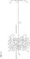
- Fig. 4 is a schematic diagram showing a lens barrel according to Embodiment 2 of the present invention, and, in Fig. 4 , because the same reference sings as those shown in Fig. 1 denote the same components or like components, an explanation of the components will be omitted hereafter.
- plano-concave lens 2' which is the second lens
- the surface on the light incidence side thereof is concave and the surface on the light emission side thereof is flat
- the plano-concave lens 2' has negative refracting power
- plano-concave lens 2' has a flat end facet 2a' on the surface on the light emission side thereof, and is held in a state in which the end facet 2a' is pressed against a lens holding surface 10 2 .
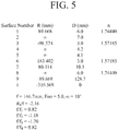
- Fig. 5 is a table diagram showing an example of lens barrel specifications, such as the radii of curvature of the surfaces of a plano-convex lens 1, the plano-concave lens 2', a meniscus lens 3, and a plano-convex lens 4, and the radius of curvature of an image surface S i .
- ⁇ shows that the radius of curvature is infinite.
- n 1 denotes the index of refraction of the plano-convex lens 1
- n 3 denotes the index of refraction of the plano-concave lens 2'
- n 6 denotes the index of refraction of the meniscus lens 3
- n 8 denotes the index of refraction of the plano-convex lens 4.
- the radii of curvature R 1 to R 9 , and R i , spacings D 1 to D 9 , the indices of refraction n 1 , n 3 , n 6 , and n 8 , the focal length f of the whole of the lens barrel, an F number Fno, and a half angle of view ⁇ have numerical values shown in Fig. 5 .
- f/f 1 0.82
- f/f 2 -1.18
- f/f 3 -1.70
- f/f 4 0.82
- RMS which is the mean square of the wavefront aberration is provided as follows.
- ⁇ denotes a wavelength of 1.55 ⁇ m.
- RMS 0.0218 ⁇ ⁇
- RMS 0.0136 ⁇ ⁇
- the wavefront aberration satisfies the wavefront aberration required for a wind measurement lidar, like in the case of above-mentioned Embodiment 1.
- the wavefront aberration in the Embodiment 2 is sufficiently allowable because RMS of the wavefront aberration required for a wind measurement lidar is typically of the order of 0.1 ⁇ or less.
- RMS of the wavefront aberration is slightly less than that in above-mentioned Embodiment 1.
- the manufacturing costs of the first, second, and fourth lenses are reduced to less than those in a case of using, for example, a biconvex lens, a meniscus lens, or the like as each of the first, second, and fourth lenses. Therefore, there is provided an advantage of providing a low-cost lens barrel that can satisfy the wavefront aberration required for a wind measurement lidar, like in the case of above-mentioned Embodiment 1.
- Embodiment 2 because the plano-concave lens 2' in which one of the surfaces thereof is flat is also used as the second lens, a lens barrel at a lower cost than that of above-mentioned Embodiment 1 is provided.
- the example in which the light emission surface of the plano-convex lens 1, the light emission surface of the plano-concave lens 2', and the light incidence surface of the plano-convex lens 4 are flat is shown. More specifically, in Fig. 5 , the example in which the radius of curvature R 2 of the light emission surface of the plano-convex lens 1, the radius of curvature R 4 of the light emission surface of the plano-concave lens 2', and the radius of curvature R 8 of the light incidence surface of the plano-convex lens 4 are infinite is shown.
- R 2 , R 4 , and R 8 should just be larger than 17, 000mm or smaller than -17, 000mm, and are not limited to infinity.
- the radii of curvature R 2 , R 4 , and R 8 are not infinite, such as in the case in which the radii of curvature R 2 , R 4 , and R 8 are larger than 17, 000mm or smaller than -17, 000mm, a wavefront aberration which is identical to the wavefront aberration shown by the equation (13) or (14) is provided, and can satisfy the wavefront aberration required for a wind measurement lidar. Therefore, even in the case in which the radii of curvature R 2 , R 4 , and R 8 are larger than 17,000mm or smaller than -17, 000mm due to manufacturing tolerances or the like, the identical wavefront aberration is maintained.
- the third lens is the meniscus lens 3 in which the surface on the light incidence side thereof is convex and the surface on the light emission side thereof is concave is shown
- a third lens is a plano-concave lens in which a surface on a light incidence side thereof is flat and a surface on a light emission side thereof is concave will be explained.
- Fig. 6 is a schematic diagram showing a lens barrel according to the Embodiment 3 of the present invention, and, in Fig. 6 , because the same reference signs as those shown in Fig. 4 denote the same components or like components, an explanation of the components will be omitted hereafter.
- plano-concave lens 3' which is the third lens, the surface on the light incidence side thereof is flat and the surface on the light emission side thereof is concave, and the plano-concave lens 3' has negative refracting power.
- plano-concave lens 3' has a flat end facet 3a' on the surface on the light incidence side thereof, and is held in a state in which the end facet 3a' is pressed against a lens holding surface 10 3 .
- plano-concave lens 3' which is the third lens is used in the lens barrel of Fig. 4 in which the plano-concave lens 2' is mounted is shown
- the plano-concave lens 3' can be used in the lens barrel of Fig. 1 in which the biconcave lens 2 is mounted.
- Fig. 7 is a table diagram showing an example of lens barrel specifications, such as the radii of curvature of the surfaces of a plano-convex lens 1, the plano-concave lens 2', the plano-concave lens 3', and a plano-convex lens 4, and the radius of curvature of an image surface S i .
- ⁇ shows that the radius of curvature is infinite.
- n 1 denotes the index of refraction of the plano-convex lens 1
- n 3 denotes the index of refraction of the plano-concave lens 2'
- n 6 denotes the index of refraction of the plano-concave lens 3'
- n 8 denotes the index of refraction of the plano-convex lens 4.
- the radii of curvature R 1 to R 9 , and R i , spacings D 1 to D 9 , the indices of refraction n 1 , n 3 , n 6 , and n 8 , the focal length f of the whole of the lens barrel, an F number Fno, and a half angle of view ⁇ have numerical values shown in Fig. 7 .
- f/f 1 0.71
- f/f 2 -1.17
- f/f 3 -1.01
- f/f 4 0.71
- RMS which is the mean square of the wavefront aberration is provided as follows.
- ⁇ denotes a wavelength of 1.55 ⁇ m.
- RMS 0 ⁇ .0345 ⁇ ⁇
- RMS 0 ⁇ .0107 ⁇ ⁇
- the wavefront aberration satisfies the wavefront aberration required for a wind measurement lidar, like in the case of above-mentioned Embodiment 1.
- the wavefront aberration in the Embodiment 3 is sufficiently allowable because RMS of the wavefront aberration required for a wind measurement lidar is typically of the order of 0.1 ⁇ or less.
- RMS of the wavefront aberration is slightly less than those in above-mentioned Embodiments 1 and 2.
- the manufacturing costs of the first through fourth lenses are reduced to less than those in a case of using, for example, a biconvex lens, a meniscus lens, or the like as each of the first through fourth lenses. Therefore, there is provided an advantage of providing a low-cost lens barrel that can satisfy the wavefront aberration required for a wind measurement lidar, like in the case of above-mentioned Embodiments 1 and 2.
- Embodiment 3 because the plano-concave lens 3' in which one of the surfaces thereof is flat is also used as the third lens, a lens barrel at a lower cost than those of above-mentioned Embodiments 1 and 2 is provided.
- the example in which the light emission surface of the plano-convex lens 1, the light emission surface of the plano-concave lens 2', the light incidence surface of the plano-concave lens 3', and the light incidence surface of the plano-convex lens 4 are flat is shown. More specifically, in Fig.
- the radius of curvature R 2 of the light emission surface of the plano-convex lens 1, the radius of curvature R 4 of the light emission surface of the plano-concave lens 2', the radius of curvature R 6 of the light incidence surface of the plano-concave lens 3', and the radius of curvature R 8 of the light incidence surface of the plano-convex lens 4 are infinite.
- the radii of curvature R 2 , R 4 , R 6 , and R 8 should just be larger than 17,000mm or smaller than -17,000mm, and are not limited to infinity.
- the radii of curvature R 2 , R 4 , R 6 , and R 8 are not infinite, such as in the case in which the radii of curvature R 2 , R 4 , R 6 , and R 8 are larger than 17,000mm or smaller than -17,000mm, a wavefront aberration which is identical to the wavefront aberration shown by the equation (18) or (19) is provided, and can satisfy the wavefront aberration required for a wind measurement lidar. Therefore, even in the case in which the radii of curvature R 2 , R 4 , R 6 , and R 8 are larger than 17, 000mm or smaller than -17,000mm due to manufacturing tolerances or the like, the identical wavefront aberration is maintained.
- the present invention is suitable for a lens barrel that images incident light onto an image surface.
Landscapes
- Physics & Mathematics (AREA)
- General Physics & Mathematics (AREA)
- Optics & Photonics (AREA)
- Lenses (AREA)
- Lens Barrels (AREA)
Abstract
Description
- The present invention relates to a lens barrel that images incident light onto an image surface.
- There is a case in which a lens barrel is used as an optical antenna of a wind measurement lidar that measures a wind direction and a wind velocity in the atmosphere by transmitting and receiving laser light.
- A variation may be caused in the performance of a lens barrel after assembly due to the erection tolerance.
- In a lens barrel disclosed in
Patent Literature 1 mentioned later, in order to suppress the erection tolerance, a flat surface is formed on each of end facets of two lenses held in the barrel while each of lens holding surfaces of the barrel for holding the two lenses is formed into the flat surface, and the two lenses are fixed in a state in which the end facets of the two lenses are pressed against the lens holding surfaces of the barrel. - Out of the two lenses, a first lens is a biconvex one in which both surfaces thereof are convex, and a second lens is a meniscus one in which a surface on an incidence side thereof is convex and a surface on an emission side thereof is concave.
- Patent Literature 1: Japanese Unexamined Patent Application Publication No.
2014-77904 - Because the conventional lens barrel is structured as above, the erection tolerance can be suppressed, but, in a case in which the lens barrel is used as an optical antenna of a wind measurement lidar, the wavefront aberration required for the wind measurement lidar may be unable to be satisfied because the number of lenses held in the barrel is only two. In order to improve the performance of the wavefront aberration, it is necessary to increase the number of lenses held in the barrel, and the wavefront aberration required for a wind measurement lidar can be satisfied if the number of lenses held in the barrel is four. However, there is a problem in that it is troublesome to process the surfaces of a biconvex lens and a meniscus lens, and the structure of holding four lenses including a biconvex lens and a meniscus lens causes an increase in the manufacturing cost.
- The present invention is made in order to solve the above-mentioned problem, and it is therefore an object of the present invention to provide a low-cost lens barrel that can satisfy the wavefront aberration required for a wind measurement lidar.
- According to the present invention, there is provided a lens barrel including: a first lens in which a surface on a light incidence side thereof is convex and a surface on a light emission side thereof is flat; a second lens having negative refracting power on which light emitting from the first lens is incident; a third lens having negative refracting power on which light emitting from the second lens is incident; a fourth lens in which a surface on a light incidence side thereof is flat and a surface on a light emission side thereof is convex, and on which light emitting from the third lens is incident; and a barrel for holding the first through fourth lenses.
- According to the present invention, because one of the surfaces of each of the first through fourth lenses is flat, the manufacturing costs of the first through fourth lenses are reduced. Therefore, there is provided an advantage of providing a low-cost lens barrel that can satisfy the wavefront aberration required for a wind measurement lidar.
-
-
Fig. 1 is a schematic diagram showing a lens barrel according toEmbodiment 1 of the present invention; -
Fig. 2 is an enlarged view showing abiconcave lens 2 and ameniscus lens 3 of the lens barrel according to Embodiment 1 of present invention; -
Fig. 3 is a table diagram showing an example of lens barrel specifications, such as the radii of curvature of surfaces of a plano-convex lens 1, thebiconcave lens 2, themeniscus lens 3, and a plano-convex lens 4, and an image surface Si; -
Fig. 4 is a schematic diagram showing a lens barrel according toEmbodiment 2 of the present invention; -
Fig. 5 is a table diagram showing an example of lens barrel specifications, such as the radii of curvature of surfaces of a plano-convex lens 1, a plano-concave lens 2', ameniscus lens 3, and a plano-convex lens 4, and the radius of curvature of an image surface Si; -
Fig. 6 is a schematic diagram showing a lens barrel according toEmbodiment 3 of the present invention; and -
Fig. 7 is a table diagram showing an example of lens barrel specifications, such as the radii of curvature of surfaces of a plano-convex lens 1, a plano-concave lens 2', a plano-concave lens 3', and a plano-convex lens 4, and the radius of curvature of an image surface Si. - Hereafter, in order to explain this invention in greater detail, the embodiments of the present invention will be described with reference to the accompanying drawings.
-
Fig. 1 is a schematic diagram showing a lens barrel according toEmbodiment 1 of the present invention, andFig. 2 is an enlarged view showing abiconcave lens 2 and ameniscus lens 3 of the lens barrel according toEmbodiment 1 of the present invention. - In
Figs. 1 and2 , thebarrel 10 is a lens holding member holding a plano-convex lens 1 (first lens), the biconcave lens 2 (second lens), the meniscus lens 3 (third lens), and a plano-convex lens 4 (fourth lens), and has, as flat lens holding surfaces, a lens holding surface 101 (first lens holding surface), a lens holding surface 102 (second lens holding surface), a lens holding surface 103 (third lens holding surface), and a lens holding surface 104 (fourth lens holding surface) in order from a light incidence side thereof. - As for the plano-
convex lens 1, a surface on a light incidence side thereof is convex and a surface on a light emission side thereof is flat, and the plano-convex lens 1 has positive refracting power. - Further, the plano-
convex lens 1 has a flat end facet 1a on the surface on the light emission side thereof, and is held in a state in which the end facet 1a is pressed against thelens holding surface 101. - Both surfaces of the
biconcave lens 2 are concave, and thebiconcave lens 2 has negative refracting power. - Further, the
biconcave lens 2 has aflat end facet 2a on a surface on a light emission side thereof, and is held in a state in which theend facet 2a is pressed against thelens holding surface 102. - As for the
meniscus lens 3, a surface on a light incidence side thereof is convex and a surface on a light emission side thereof is concave, and themeniscus lens 3 has negative refracting power. - Further, the
meniscus lens 3 has aflat end facet 3a on the surface on the light emission side thereof, and is held in a state in which theend facet 3a is pressed against thelens holding surface 103. - As for the plano-
convex lens 4, a surface on a light incidence side thereof is flat and a surface on a light emission side thereof is convex, and the plano-convex lens 4 has positive refracting power. - Further, the plano-
convex lens 4 has aflat end facet 4a on the surface on the light incidence side thereof, and is held in a state in which theend facet 4a is pressed against thelens holding surface 104. - An
aperture 20 is disposed between thebiconcave lens 2 and themeniscus lens 3. - Only one of the surfaces of each of the plano-
convex lenses convex lenses biconcave lens 2 and themeniscus lens 3 because of grinding. - R1 denotes the radius of curvature of the light incidence surface of the plano-
convex lens 1, and R2 denotes the radius of curvature of the light emission surface of the plano-convex lens 1. - R3 denotes the radius of curvature of the light incidence surface of the
biconcave lens 2, and R4 denotes the radius of curvature of the light emission surface of thebiconcave lens 2. - R5 denotes the radius of curvature of the
aperture 20. - R6 denotes the radius of curvature of the light incidence surface of the
meniscus lens 3, and R7 denotes the radius of curvature of the light emission surface of themeniscus lens 3. - R8 denotes the radius of curvature of the light incidence surface of the plano-
convex lens 4, and R9 denotes the radius of curvature of the light emission surface of the plano-convex lens 4. - D1 denotes the spacing on an optical axis X between the light incidence surface and the light emission surface of the plano-
convex lens 1, and D2 denotes the spacing on the optical axis X between the light emission surface of the plano-convex lens 1 and the light incidence surface of thebiconcave lens 2. - D3 denotes the spacing on the optical axis X between the light incidence surface and the light emission surface of the
biconcave lens 2, D4 denotes the spacing on the optical axis X between the light emission surface of thebiconcave lens 2 and theaperture 20, and D5 denotes the spacing on the optical axis X between theaperture 20 and the light incidence surface of themeniscus lens 3. - D6 denotes the spacing on the optical axis X between the light incidence surface and the light emission surface of the
meniscus lens 3, and D7 denotes the spacing on the optical axis X between the light emission surface of themeniscus lens 3 and the light incidence surface of the plano-convex lens 4. - D8 denotes the spacing on the optical axis X between the light incidence surface and the light emission surface of the plano-
convex lens 4, and D9 denotes the spacing on the optical axis X between the light emission surface of the plano-convex lens 4 and a position P on an image surface Si where an image is formed. - Here, it is assumed that the focal length of the whole of the lens barrel is denoted by f, the focal length of the plano-
convex lens 1 is denoted by f1, the focal length of thebiconcave lens 2 is denoted by f2, the focal length of themeniscus lens 3 is denoted by f3, and the focal length of the plano-convex lens 4 is denoted by f4. Further, it is assumed that the radius of curvature of the image surface Si where light is imaged by the lens barrel is denoted by Ri. - In
Embodiments 1 to 3 including theEmbodiment 1, by causing the following condition (1) to be satisfied, the degradation in the performance of the wavefront aberration for the rotation tolerance of the whole of the lens barrel is reduced.
- Further, in
Embodiments 1 to 3 including theEmbodiment 1, by causing the following conditions (2) to (5) to be satisfied, high performance of the wavefront aberration is provided and the erection tolerance of the lens barrel is reduced.


- Next, operations will be explained.
- A light flux from an object side which is a light incidence side is incident on the lens barrel along the optical axis X.
- The light flux incident on the lens barrel passes through the plano-
convex lens 1, thebiconcave lens 2, themeniscus lens 3, and the plano-convex lens 4, so that the light flux is imaged at the image formation position P on the image surface Si. -
Fig. 3 is a table diagram showing an example of lens barrel specifications, such as the radii of curvature of the surfaces of the plano-convex lens 1, thebiconcave lens 2, themeniscus lens 3, and the plano-convex lens 4, and the radius of curvature of the image surface Si. - In
Fig. 3 , ∞ shows that the radius of curvature is infinite. n1 denotes the index of refraction of the plano-convex lens 1, n3 denotes the index of refraction of thebiconcave lens 2, n6 denotes the index of refraction of themeniscus lens 3, and n8 denotes the index of refraction of the plano-convex lens 4. - In the
Embodiment 1, the radii of curvature R1 to R9, and Ri, the spacings D1 to D9, the indices of refraction n1, n3, n6, and n8, the focal length f of the whole of the lens barrel, an F number Fno, and a half angle of view ω have numerical values shown inFig. 3 . - Using these numerical values, Ri/f=-2.14 is provided as shown in
Fig. 3 , and the condition (1) is satisfied. - Further, f/f1=0.82, f/f2=-0. 96, f/f3=-2.55, and f/f4=0.82 are provided, and the conditions (2) to (5) are satisfied.
- In the example of
Fig. 3 , as to the radii of curvature, their values on the light incidence side are positive. - When a simulation of the wavefront aberration of the lens barrel expressed by the above-mentioned numerical values is performed, RMS which is the mean square of the wavefront aberration is provided as follows. λ denotes a wavelength of 1.55µm.

- Although the equation (6) shows a case in which the half angle of view ω is 10 degrees, in a case in which the half angle of view ω is 0 degrees, RMS which is the mean square of the wavefront aberration is provided as follows.

- Not only in the case in which the half angle of view ω is 0 degrees, but also in the case in which the half angle of view ω is 10 degrees, the wavefront aberration satisfies the wavefront aberration required for a wind measurement lidar.
- Incidentally, because RMS of the wavefront aberration required for a wind measurement lidar is typically of the order of 0.1λ or less, the requirement is fully satisfied.
- As is clear from the above description, according to the
Embodiment 1, because the light emission surface of the plano-convex lens 1 which is the first lens and the light incidence surface of the plano-convex lens 4 which is the fourth lens are flat, the manufacturing costs of the first and fourth lenses are reduced to less than those in a case of using, for example, a biconvex lens, a meniscus lens, or the like as each of the first and fourth lenses. Therefore, there is provided an advantage of providing a low-cost lens barrel that can satisfy the wavefront aberration required for a wind measurement lidar. - Further, according to the
Embodiment 1, because the plano-convex lens 1 is held in the state in which the flat end facet 1a is pressed against the flatlens holding surface 101, thebiconcave lens 2 is held in the state in which theflat end facet 2a is pressed against the flatlens holding surface 102, themeniscus lens 3 is held in the state in which theflat end facet 3a is pressed against the flatlens holding surface 103, and the plano-convex lens 4 is held in the state in which theflat end facet 4a is pressed against the flatlens holding surface 104, the tolerance at the time of assembly can be reduced and the degradation in the performance of the wavefront aberration can be suppressed. - In the
Embodiment 1, because the radius of curvature R1 of the plano-convex lens 1 and the radius of curvature R9 of the plano-convex lens 4 are identical, and the index of refraction n1 of the plano-convex lens 1 and the index of refraction n8 of the plano-convex lens 4 are identical, as shown inFig. 3 , it is possible to process the plano-convex lenses - Because the orientations of the plano-
convex lens 1 and the plano-convex lens 4 are opposite to each other, the radius of curvature R1 of the plano-convex lens 1 and the radius of curvature R9 of the plano-convex lens 4 have opposite signs, i.e., R1=89.609 and R9=-89.609, as shown inFig. 3 , but the radii of curvature of the lenses themselves are identical. - In the
Embodiment 1, because the radius of curvature Ri of the image surface Si where light is imaged by the lens barrel has a negative radius of curvature for the focal length f of the whole of the lens barrel, the degradation in the performance of the wavefront aberration for the rotation tolerance of the whole of the lens barrel can be reduced to less than that of a case in which the image surface Si where light is imaged by the lens barrel is flat. - Incidentally, in a case of a normal camera lens, because the light receiving surface is flat, the light receiving surface and the image surface do not match each other if the image surface has a radius of curvature. As a result, blurring occurs in the image in accordance with the angle of view.
- In a case in which the lens barrel is used as an optical antenna of a wind measurement lidar, an optical fiber is typically used for input and output of laser light to and from the lens barrel. Therefore, at the position of an end of the fiber, the position being on the image surface, the angle of view is specified as a point instead of a surface. Therefore, because even in a case in which the image surface has a radius of curvature, the fiber end should just be arranged on the image surface having this radius of curvature, blurring like that occurring in the case of a camera lens does not occur.
- Further, when the whole image is captured with a high degree of resolution by a camera, the performance of the wavefront aberration which determines the image formation performance need be maintained in all the angles of view falling within a certain angle-of-view range determined by both the size of the light receiving surface and the focal length.
- In the case in which the lens barrel is used as an optical antenna of a wind measurement lidar, because the angle of view is determined by the position on the image surface of the fiber end, the angle of view at which the performance of the wavefront aberration should be maintained does not fall within such a wide range as that in the case of a camera lens, but is a specific one. Therefore, because it is only required to improve the performance of the wavefront aberration for a specific angle of view, the constraints are eased, and, as a result, high performance of the wavefront aberration can be provided.
- In a wind measurement lidar that measures a wind direction and a wind velocity in the atmosphere by transmitting and receiving laser light, a wind velocity in a line-of-sight direction is measured by using the Doppler effect, and a wind direction is calculated from wind velocities in multiple line-of-sight directions. Therefore, fiber ends are arranged for multiple angles of view, laser light is transmitted and received at each of the fiber ends corresponding to the multiple angles of view, and a wind velocity at each of the angles of view is calculated.
- In the
Embodiment 1, a wavefront aberration in the case in which the half angle of view ω is 0 degrees and a wavefront aberration in the case in which the half angle of view ω is 10 degrees are measured, and either of the wavefront aberrations satisfies the wavefront aberration required for the wind measurement lidar. - Although in the
Embodiment 1, the example in which the index of refraction n1 of the plano-convex lens 1 and the index of refraction n8 of the plano-convex lens 4 are identical as shown inFig. 3 is shown, the plano-convex lens 1 and the plano-convex lens 4 can be manufactured using glass materials causing the refractive index difference Δn1-8 between the plano-convex lens 1 and the plano-convex lens 4 to fall within a range of ±0.0006.
- Further, although the example in which the index of refraction n3 of the
biconcave lens 2 and the index of refraction n6 of themeniscus lens 3 are identical is shown, thebiconcave lens 2 and themeniscus lens 3 can be manufactured using glass materials causing the refractive index difference Δn3-6 between thebiconcave lens 2 and themeniscus lens 3 to fall within a range of ±0.0006.
- In the case in which the refractive index difference falls within the range of ±0.0006, a wavefront aberration which is identical to the wavefront aberration shown by the equation (6) or (7) is provided, and can satisfy the wavefront aberration required for a wind measurement lidar. Therefore, even though a variation in the index of refraction occurs within the range of ±0.0006 due to manufacturing tolerances or the like, the identical wavefront aberration is maintained.
- Although in the
Embodiment 1, the example in which the radius of curvature R1 of the light incidence surface of the plano-convex lens 1 and the radius of curvature R9 of the light emission surface of the plano-convex lens 4 are identical is shown, the radius of curvature R1 and the radius of curvature R9 can differ from each other as long as the difference ΔR1-9 between the radius of curvature R1 and the radius of curvature R9 falls within a range of ±0.47mm.
- In the case in which the difference ΔR1-9 between the radius of curvature R1 and the radius of curvature R9 falls within the range of ±0.47mm, a wavefront aberration which is identical to the wavefront aberration shown by the equation (6) or (7) is provided, and can satisfy the wavefront aberration required for a wind measurement lidar. Therefore, even though a variation in the radius of curvature occurs within the range of ±0.47mm due to manufacturing tolerances or the like, the identical wavefront aberration is maintained.
- In the
Embodiment 1, the example in which the light emission surface of the plano-convex lens 1 and the light incidence surface of the plano-convex lens 4 are flat is shown. More specifically, inFig. 3 , the example in which the radius of curvature R2 of the light emission surface of the plano-convex lens 1 and the radius of curvature R8 of the light incidence surface of the plano-convex lens 4 are infinite is shown. However, the radii of curvature R2 and R8 should just be larger than 17,000mm or smaller than -17,000mm, and are not limited to infinity.

- Even though the radii of curvature R2 and R8 are not infinite, such as in the case in which the radii of curvature R2 and R8 are larger than 17,000mm or smaller than -17,000mm, a wavefront aberration which is identical to the wavefront aberration shown by the equation (6) or (7) is provided, and can satisfy the wavefront aberration required for a wind measurement lidar. Therefore, even in the case in which the radii of curvature R2 and R8 are larger than 17, 000mm or smaller than -17, 000mm due to manufacturing tolerances or the like, the identical wavefront aberration is maintained.
- Although in
Embodiment 1, the example in which the second lens is thebiconcave lens 2 in which both the surfaces thereof are concave is shown, in theEmbodiment 2, an example in which a second lens is a plano-concave lens in which a surface on a light incidence side thereof is concave and a surface on a light emission side thereof is flat will be explained. -
Fig. 4 is a schematic diagram showing a lens barrel according toEmbodiment 2 of the present invention, and, inFig. 4 , because the same reference sings as those shown inFig. 1 denote the same components or like components, an explanation of the components will be omitted hereafter. - In a plano-concave lens 2' which is the second lens, the surface on the light incidence side thereof is concave and the surface on the light emission side thereof is flat, and the plano-concave lens 2' has negative refracting power.
- Further, the plano-concave lens 2' has a
flat end facet 2a' on the surface on the light emission side thereof, and is held in a state in which theend facet 2a' is pressed against alens holding surface 102. -
Fig. 5 is a table diagram showing an example of lens barrel specifications, such as the radii of curvature of the surfaces of a plano-convex lens 1, the plano-concave lens 2', ameniscus lens 3, and a plano-convex lens 4, and the radius of curvature of an image surface Si. - In
Fig. 5 , ∞ shows that the radius of curvature is infinite. n1 denotes the index of refraction of the plano-convex lens 1, n3 denotes the index of refraction of the plano-concave lens 2', n6 denotes the index of refraction of themeniscus lens 3, and n8 denotes the index of refraction of the plano-convex lens 4. - In the
Embodiment 2, the radii of curvature R1 to R9, and Ri, spacings D1 to D9, the indices of refraction n1, n3, n6, and n8, the focal length f of the whole of the lens barrel, an F number Fno, and a half angle of view ω have numerical values shown inFig. 5 . - Using these numerical values, Ri/f=-2.16 is provided as shown in
Fig. 5 , and the above-mentioned condition (1) is satisfied. - Further, f/f1=0.82, f/f2=-1.18, f/f3=-1.70, and f/f4=0.82 are provided, and the above-mentioned conditions (2) to (5) are satisfied.
- When a simulation of the wavefront aberration of the lens barrel expressed by the above-mentioned numerical values is performed, RMS which is the mean square of the wavefront aberration is provided as follows. λ denotes a wavelength of 1.55 µm.

- Although the equation (13) shows a case in which the half angle of view ω is 10 degrees, in a case in which the half angle of view ω is 0 degrees, RMS which is the mean square of the wavefront aberration is provided as follows.

- Not only in the case in which the half angle of view ω is 0 degrees, but also in the case in which the half angle of view ω is 10 degrees, the wavefront aberration satisfies the wavefront aberration required for a wind measurement lidar, like in the case of above-mentioned
Embodiment 1. - Although in the case in which the half angle of view ω is 10 degrees, RMS of the wavefront aberration is slightly greater than that in above-mentioned
Embodiment 1, the wavefront aberration in theEmbodiment 2 is sufficiently allowable because RMS of the wavefront aberration required for a wind measurement lidar is typically of the order of 0.1λ or less. - In the case in which the half angle of view ω is 0 degrees, RMS of the wavefront aberration is slightly less than that in above-mentioned
Embodiment 1. - As is clear from the above description, according to the
Embodiment 2, because the light emission surface of the plano-convex lens 1 which is the first lens, the light emission surface of the plano-concave lens 2' which is the second lens, and the light incidence surface of the plano-convex lens 4 which is the fourth lens are flat, the manufacturing costs of the first, second, and fourth lenses are reduced to less than those in a case of using, for example, a biconvex lens, a meniscus lens, or the like as each of the first, second, and fourth lenses. Therefore, there is provided an advantage of providing a low-cost lens barrel that can satisfy the wavefront aberration required for a wind measurement lidar, like in the case of above-mentionedEmbodiment 1. - In addition, in the
Embodiment 2, because the plano-concave lens 2' in which one of the surfaces thereof is flat is also used as the second lens, a lens barrel at a lower cost than that of above-mentionedEmbodiment 1 is provided. - In the
Embodiment 2, the example in which the light emission surface of the plano-convex lens 1, the light emission surface of the plano-concave lens 2', and the light incidence surface of the plano-convex lens 4 are flat is shown. More specifically, inFig. 5 , the example in which the radius of curvature R2 of the light emission surface of the plano-convex lens 1, the radius of curvature R4 of the light emission surface of the plano-concave lens 2', and the radius of curvature R8 of the light incidence surface of the plano-convex lens 4 are infinite is shown. However, the radii of curvature R2, R4, and R8 should just be larger than 17, 000mm or smaller than -17, 000mm, and are not limited to infinity.


- Even though the radii of curvature R2, R4, and R8 are not infinite, such as in the case in which the radii of curvature R2, R4, and R8 are larger than 17, 000mm or smaller than -17, 000mm, a wavefront aberration which is identical to the wavefront aberration shown by the equation (13) or (14) is provided, and can satisfy the wavefront aberration required for a wind measurement lidar. Therefore, even in the case in which the radii of curvature R2, R4, and R8 are larger than 17,000mm or smaller than -17, 000mm due to manufacturing tolerances or the like, the identical wavefront aberration is maintained.
- Although in the
Embodiments meniscus lens 3 in which the surface on the light incidence side thereof is convex and the surface on the light emission side thereof is concave is shown, in theEmbodiment 3, an example in which a third lens is a plano-concave lens in which a surface on a light incidence side thereof is flat and a surface on a light emission side thereof is concave will be explained. -
Fig. 6 is a schematic diagram showing a lens barrel according to theEmbodiment 3 of the present invention, and, inFig. 6 , because the same reference signs as those shown inFig. 4 denote the same components or like components, an explanation of the components will be omitted hereafter. - In a plano-concave lens 3' which is the third lens, the surface on the light incidence side thereof is flat and the surface on the light emission side thereof is concave, and the plano-concave lens 3' has negative refracting power.
- Further, the plano-concave lens 3' has a
flat end facet 3a' on the surface on the light incidence side thereof, and is held in a state in which theend facet 3a' is pressed against alens holding surface 103. - Although in
Fig. 6 , the example in which the plano-concave lens 3' which is the third lens is used in the lens barrel ofFig. 4 in which the plano-concave lens 2' is mounted is shown, the plano-concave lens 3' can be used in the lens barrel ofFig. 1 in which thebiconcave lens 2 is mounted. - In the example of
Fig. 6 , because theend facet 3a' of the plano-concave lens 3' is on the surface of the light incidence side, the shape of thebarrel 10 on thelens holding surface 103 differs from those of thebarrels 10 ofFigs. 1 and4 . -
Fig. 7 is a table diagram showing an example of lens barrel specifications, such as the radii of curvature of the surfaces of a plano-convex lens 1, the plano-concave lens 2', the plano-concave lens 3', and a plano-convex lens 4, and the radius of curvature of an image surface Si. - In
Fig. 7 , ∞ shows that the radius of curvature is infinite. n1 denotes the index of refraction of the plano-convex lens 1, n3 denotes the index of refraction of the plano-concave lens 2', n6 denotes the index of refraction of the plano-concave lens 3', and n8 denotes the index of refraction of the plano-convex lens 4. - In the
Embodiment 3, the radii of curvature R1 to R9, and Ri, spacings D1 to D9, the indices of refraction n1, n3, n6, and n8, the focal length f of the whole of the lens barrel, an F number Fno, and a half angle of view ω have numerical values shown inFig. 7 . - Using these numerical values, Ri/f=-2.36 is provided as shown in
Fig. 7 , and the above-mentioned condition (1) is satisfied. - Further, f/f1=0.71, f/f2=-1.17, f/f3=-1.01, and f/f4=0.71 are provided, and the above-mentioned conditions (2) to (5) are satisfied.
- When a simulation of the wavefront aberration of the lens barrel expressed by the above-mentioned numerical values is performed, RMS which is the mean square of the wavefront aberration is provided as follows. λ denotes a wavelength of 1.55 µm.

- Although the equation (18) shows a case in which the half angle of view ω is 10 degrees, in a case in which the half angle of view ω is 0 degrees, RMS which is the mean square of the wavefront aberration is provided as follows.

- Not only in the case in which the half angle of view ω is 0 degrees, but also in the case in which the half angle of view ω is 10 degrees, the wavefront aberration satisfies the wavefront aberration required for a wind measurement lidar, like in the case of above-mentioned
Embodiment 1. - Although in the case in which the half angle of view ω is 10 degrees, RMS of the wavefront aberration is slightly greater than those in above-mentioned
Embodiments Embodiment 3 is sufficiently allowable because RMS of the wavefront aberration required for a wind measurement lidar is typically of the order of 0.1λ or less. - In the case in which the half angle of view ω is 0 degrees, RMS of the wavefront aberration is slightly less than those in above-mentioned
Embodiments - As is clear from the above description, according to the
Embodiment 3, because the light emission surface of the plano-convex lens 1 which is the first lens, the light emission surface of the plano-concave lens 2' which is the second lens, the light incidence surface of the plano-concave lens 3' which is the third lens, and the light incidence surface of the plano-convex lens 4 which is the fourth lens are flat, the manufacturing costs of the first through fourth lenses are reduced to less than those in a case of using, for example, a biconvex lens, a meniscus lens, or the like as each of the first through fourth lenses. Therefore, there is provided an advantage of providing a low-cost lens barrel that can satisfy the wavefront aberration required for a wind measurement lidar, like in the case of above-mentionedEmbodiments - In addition, in the
Embodiment 3, because the plano-concave lens 3' in which one of the surfaces thereof is flat is also used as the third lens, a lens barrel at a lower cost than those of above-mentionedEmbodiments - In the
Embodiment 3, the example in which the light emission surface of the plano-convex lens 1, the light emission surface of the plano-concave lens 2', the light incidence surface of the plano-concave lens 3', and the light incidence surface of the plano-convex lens 4 are flat is shown. More specifically, inFig. 7 , the example in which the radius of curvature R2 of the light emission surface of the plano-convex lens 1, the radius of curvature R4 of the light emission surface of the plano-concave lens 2', the radius of curvature R6 of the light incidence surface of the plano-concave lens 3', and the radius of curvature R8 of the light incidence surface of the plano-convex lens 4 are infinite is shown. However, the radii of curvature R2, R4, R6, and R8 should just be larger than 17,000mm or smaller than -17,000mm, and are not limited to infinity.


- Even though the radii of curvature R2, R4, R6, and R8 are not infinite, such as in the case in which the radii of curvature R2, R4, R6, and R8 are larger than 17,000mm or smaller than -17,000mm, a wavefront aberration which is identical to the wavefront aberration shown by the equation (18) or (19) is provided, and can satisfy the wavefront aberration required for a wind measurement lidar. Therefore, even in the case in which the radii of curvature R2, R4, R6, and R8 are larger than 17, 000mm or smaller than -17,000mm due to manufacturing tolerances or the like, the identical wavefront aberration is maintained.
- It is to be understood that any combination of two or more of the above-mentioned embodiments can be made, various changes can be made in any component according to any one of the above-mentioned embodiments, and any component according to any one of the above-mentioned embodiments can be omitted within the scope of the invention.
- The present invention is suitable for a lens barrel that images incident light onto an image surface.
- 1 plano-convex lens (first lens), 1a flat end facet, 2 biconcave lens (second lens), 2a flat end facet, 2' plano-concave lens (second lens) , 2a' flat end facet, 3 meniscus lens (third lens), 3a flat end facet, 3' plano-concave lens (third lens), 3a' flat end facet, 4 plano-convex lens (fourth lens), 4a flat end facet, 10 barrel, 101 lens holding surface (first lens holding surface), 102 lens holding surface (second lens holding surface), 103 lens holding surface (third lens holding surface), 104 lens holding surface (fourth lens holding surface), and 20 aperture.
Claims (6)
- A lens barrel comprising:a first lens in which a surface on a light incidence side thereof is convex and a surface on a light emission side thereof is flat;a second lens having negative refracting power on which light emitting from the first lens is incident;a third lens having negative refracting power on which light emitting from the second lens is incident;a fourth lens in which a surface on a light incidence side thereof is flat and a surface on a light emission side thereof is convex, and on which light emitting from the third lens is incident; anda barrel for holding the first through fourth lenses.
- The lens barrel according to claim 1,
wherein as for the second lens, a surface on a light incidence side thereof is concave and a surface on a light emission side thereof is flat. - The lens barrel according to claim 1,
wherein as for the third lens, a surface on a light incidence side thereof is flat and a surface on a light emission side thereof is concave. - The lens barrel according to claim 1,
wherein the barrel has, as flat lens holding surfaces, a first lens holding surface, a second lens holding surface, a third lens holding surface, and a fourth lens holding surface in order from a light incidence side thereof, and
wherein the first through fourth lenses have flat end facets, the first lens is held in a state in which the flat end facet thereof is pressed against the first lens holding surface, the second lens is held in a state in which the flat end facet thereof is pressed against the second lens holding surface, the third lens is held in a state in which the flat end facet thereof is pressed against the third lens holding surface, and the fourth lens is held in a state in which the flat end facet thereof is pressed against the fourth lens holding surface. - The lens barrel according to claim 1,
wherein a result of dividing a radius of curvature of an image surface where light is imaged by the first through fourth lenses by a focal length of a whole of the barrel comprised of the first through fourth lenses ranges from -2.36 to -2.14. - The lens barrel according to claim 5,
wherein a result of dividing the focal length of the whole of the barrel by a focal length of the first lens ranges from 0.71 to 0.82, a result of dividing the focal length of the whole of the barrel by a focal length of the second lens ranges from -1.18 to -0.96, a result of dividing the focal length of the whole of the barrel by a focal length of the third lens ranges from -2.55 to -1.01, and a result of dividing the focal length of the whole of the barrel by a focal length of the fourth lens ranges from 0.71 to 0.82.
Applications Claiming Priority (1)
| Application Number | Priority Date | Filing Date | Title |
|---|---|---|---|
| PCT/JP2016/074822 WO2018037532A1 (en) | 2016-08-25 | 2016-08-25 | Lens barrel |
Publications (3)
| Publication Number | Publication Date |
|---|---|
| EP3474056A1 true EP3474056A1 (en) | 2019-04-24 |
| EP3474056A4 EP3474056A4 (en) | 2019-07-31 |
| EP3474056B1 EP3474056B1 (en) | 2024-07-10 |
Family
ID=61245629
Family Applications (1)
| Application Number | Title | Priority Date | Filing Date |
|---|---|---|---|
| EP16914206.4A Active EP3474056B1 (en) | 2016-08-25 | 2016-08-25 | Lens barrel |
Country Status (5)
| Country | Link |
|---|---|
| EP (1) | EP3474056B1 (en) |
| JP (1) | JP6388753B2 (en) |
| CN (1) | CN109643007B (en) |
| DK (1) | DK3474056T3 (en) |
| WO (1) | WO2018037532A1 (en) |
Families Citing this family (1)
| Publication number | Priority date | Publication date | Assignee | Title |
|---|---|---|---|---|
| DE102019131000B3 (en) * | 2019-11-15 | 2020-10-01 | Jenoptik Optical Systems Gmbh | Lens, use of a lens and measuring system |
Family Cites Families (20)
| Publication number | Priority date | Publication date | Assignee | Title |
|---|---|---|---|---|
| JPH01261615A (en) * | 1988-04-12 | 1989-10-18 | Minolta Camera Co Ltd | Lens system for projection |
| SE468335B (en) * | 1988-09-15 | 1992-12-14 | Nova Onab Optica Ab | PROJECTION OPTICS |
| JPH0886958A (en) * | 1994-09-14 | 1996-04-02 | Hitachi Ltd | Single focus lens |
| JPH10186227A (en) * | 1996-10-24 | 1998-07-14 | Asahi Optical Co Ltd | telescope lens |
| JP2005278133A (en) * | 2003-07-03 | 2005-10-06 | Fuji Photo Film Co Ltd | Solid-state imaging device and optical apparatus |
| CN100462763C (en) * | 2004-11-08 | 2009-02-18 | 松下电器产业株式会社 | Lens unit |
| JP2009223251A (en) * | 2008-03-19 | 2009-10-01 | Olympus Corp | Image pickup apparatus |
| JP2011133815A (en) * | 2009-12-25 | 2011-07-07 | Sony Corp | Lens barrel and imaging apparatus |
| JP2013025202A (en) * | 2011-07-22 | 2013-02-04 | Konica Minolta Advanced Layers Inc | Image pickup lens and image pickup apparatus |
| JP2013061476A (en) * | 2011-09-13 | 2013-04-04 | Sony Corp | Lens optical unit and imaging device |
| US9104018B2 (en) * | 2012-03-30 | 2015-08-11 | Canon Kabushiki Kaisha | Imaging apparatus having a curved image surface |
| CN103076669B (en) * | 2012-07-20 | 2015-05-13 | 玉晶光电(厦门)有限公司 | Portable electronic device and optical imaging lens thereof |
| JP2014077904A (en) * | 2012-10-11 | 2014-05-01 | Olympus Corp | Manufacturing method of optical assembly and designing method of a lens to be assembled |
| CN103135204B (en) * | 2012-10-31 | 2016-08-17 | 玉晶光电(厦门)有限公司 | Portable electronic devices and its optical imaging lens |
| TW201431373A (en) * | 2013-01-30 | 2014-08-01 | Sony Corp | Image pickup device and electronic apparatus |
| US9465191B2 (en) * | 2013-06-21 | 2016-10-11 | Microsoft Technology Licensing, Llc | Lenses for curved sensor systems |
| CN104238116A (en) * | 2014-09-15 | 2014-12-24 | 中国科学院上海光学精密机械研究所 | Large-visual-field high-resolution photoelectronic imaging system |
| CN104296694B (en) * | 2014-09-28 | 2018-01-12 | 中国科学院光电研究院 | The detection means and method of a kind of laser tracker optical axis and mechanical rotating shaft angle |
| CN105552574A (en) * | 2016-03-13 | 2016-05-04 | 北京工业大学 | Millimeter wave antenna |
| JP2017207658A (en) * | 2016-05-19 | 2017-11-24 | オリンパス株式会社 | Imaging device and capsule endoscope |
-
2016
- 2016-08-25 EP EP16914206.4A patent/EP3474056B1/en active Active
- 2016-08-25 WO PCT/JP2016/074822 patent/WO2018037532A1/en not_active Ceased
- 2016-08-25 JP JP2018526965A patent/JP6388753B2/en active Active
- 2016-08-25 CN CN201680088525.2A patent/CN109643007B/en active Active
- 2016-08-25 DK DK16914206.4T patent/DK3474056T3/en active
Also Published As
| Publication number | Publication date |
|---|---|
| EP3474056B1 (en) | 2024-07-10 |
| JPWO2018037532A1 (en) | 2018-08-30 |
| CN109643007A (en) | 2019-04-16 |
| DK3474056T3 (en) | 2024-08-19 |
| WO2018037532A1 (en) | 2018-03-01 |
| CN109643007B (en) | 2021-07-09 |
| JP6388753B2 (en) | 2018-09-12 |
| EP3474056A4 (en) | 2019-07-31 |
Similar Documents
| Publication | Publication Date | Title |
|---|---|---|
| US20240255737A1 (en) | Lens module | |
| US10983315B2 (en) | Optical system and imaging apparatus | |
| US7855841B2 (en) | Reflex, magnifying optical system | |
| US9690080B2 (en) | Wide angle lens | |
| EP3309596B1 (en) | In-vehicle camera lens unit | |
| JP5993604B2 (en) | Infrared optical system | |
| JP5906859B2 (en) | Infrared optical system | |
| JP6301506B2 (en) | Telecentric lens | |
| US10634872B2 (en) | Optical system and image pickup apparatus including the same | |
| JP5905180B1 (en) | Wide-angle optical system and endoscope | |
| EP3767362A1 (en) | Optical system and optical apparatus | |
| WO2016047112A1 (en) | Lens system and image capture device | |
| JP2016066059A (en) | Wide-angle lens system and imaging device | |
| WO2013157658A1 (en) | Infrared zoom lens | |
| KR20170043279A (en) | Optical Imaging System | |
| JP2021092694A5 (en) | ||
| US20160291289A1 (en) | Optical element, optical system including the same, and manufacturing method | |
| US10168543B2 (en) | Collimating lens | |
| JP2026063333A (en) | Imaging lens system and imaging device | |
| EP3474056B1 (en) | Lens barrel | |
| KR20210151332A (en) | Small telephoto optical lens system | |
| US11899190B2 (en) | Zoom lens system, image capture device, and camera system | |
| US8422147B2 (en) | Image pickup lens and image pickup module | |
| KR20220159318A (en) | Optical Imaging System | |
| CN114594584A (en) | Zoom lens and monitoring equipment |
Legal Events
| Date | Code | Title | Description |
|---|---|---|---|
| STAA | Information on the status of an ep patent application or granted ep patent |
Free format text: STATUS: THE INTERNATIONAL PUBLICATION HAS BEEN MADE |
|
| PUAI | Public reference made under article 153(3) epc to a published international application that has entered the european phase |
Free format text: ORIGINAL CODE: 0009012 |
|
| STAA | Information on the status of an ep patent application or granted ep patent |
Free format text: STATUS: REQUEST FOR EXAMINATION WAS MADE |
|
| 17P | Request for examination filed |
Effective date: 20181226 |
|
| AK | Designated contracting states |
Kind code of ref document: A1 Designated state(s): AL AT BE BG CH CY CZ DE DK EE ES FI FR GB GR HR HU IE IS IT LI LT LU LV MC MK MT NL NO PL PT RO RS SE SI SK SM TR |
|
| AX | Request for extension of the european patent |
Extension state: BA ME |
|
| A4 | Supplementary search report drawn up and despatched |
Effective date: 20190627 |
|
| RIC1 | Information provided on ipc code assigned before grant |
Ipc: G02B 7/02 20060101ALI20190621BHEP Ipc: G02B 27/00 20060101ALI20190621BHEP Ipc: G02B 13/00 20060101AFI20190621BHEP Ipc: G02B 13/06 20060101ALI20190621BHEP |
|
| DAV | Request for validation of the european patent (deleted) | ||
| DAX | Request for extension of the european patent (deleted) | ||
| STAA | Information on the status of an ep patent application or granted ep patent |
Free format text: STATUS: EXAMINATION IS IN PROGRESS |
|
| 17Q | First examination report despatched |
Effective date: 20220314 |
|
| GRAP | Despatch of communication of intention to grant a patent |
Free format text: ORIGINAL CODE: EPIDOSNIGR1 |
|
| STAA | Information on the status of an ep patent application or granted ep patent |
Free format text: STATUS: GRANT OF PATENT IS INTENDED |
|
| INTG | Intention to grant announced |
Effective date: 20240429 |
|
| GRAS | Grant fee paid |
Free format text: ORIGINAL CODE: EPIDOSNIGR3 |
|
| GRAA | (expected) grant |
Free format text: ORIGINAL CODE: 0009210 |
|
| STAA | Information on the status of an ep patent application or granted ep patent |
Free format text: STATUS: THE PATENT HAS BEEN GRANTED |
|
| AK | Designated contracting states |
Kind code of ref document: B1 Designated state(s): AL AT BE BG CH CY CZ DE DK EE ES FI FR GB GR HR HU IE IS IT LI LT LU LV MC MK MT NL NO PL PT RO RS SE SI SK SM TR |
|
| REG | Reference to a national code |
Ref country code: CH Ref legal event code: EP |
|
| REG | Reference to a national code |
Ref country code: DE Ref legal event code: R096 Ref document number: 602016088390 Country of ref document: DE |
|
| REG | Reference to a national code |
Ref country code: DK Ref legal event code: T3 Effective date: 20240813 |
|
| REG | Reference to a national code |
Ref country code: LT Ref legal event code: MG9D |
|
| REG | Reference to a national code |
Ref country code: NL Ref legal event code: MP Effective date: 20240710 |
|
| PG25 | Lapsed in a contracting state [announced via postgrant information from national office to epo] |
Ref country code: PT Free format text: LAPSE BECAUSE OF FAILURE TO SUBMIT A TRANSLATION OF THE DESCRIPTION OR TO PAY THE FEE WITHIN THE PRESCRIBED TIME-LIMIT Effective date: 20241111 |
|
| REG | Reference to a national code |
Ref country code: AT Ref legal event code: MK05 Ref document number: 1702543 Country of ref document: AT Kind code of ref document: T Effective date: 20240710 |
|
| PG25 | Lapsed in a contracting state [announced via postgrant information from national office to epo] |
Ref country code: NL Free format text: LAPSE BECAUSE OF FAILURE TO SUBMIT A TRANSLATION OF THE DESCRIPTION OR TO PAY THE FEE WITHIN THE PRESCRIBED TIME-LIMIT Effective date: 20240710 |
|
| PG25 | Lapsed in a contracting state [announced via postgrant information from national office to epo] |
Ref country code: PT Free format text: LAPSE BECAUSE OF FAILURE TO SUBMIT A TRANSLATION OF THE DESCRIPTION OR TO PAY THE FEE WITHIN THE PRESCRIBED TIME-LIMIT Effective date: 20241111 Ref country code: NL Free format text: LAPSE BECAUSE OF FAILURE TO SUBMIT A TRANSLATION OF THE DESCRIPTION OR TO PAY THE FEE WITHIN THE PRESCRIBED TIME-LIMIT Effective date: 20240710 |
|
| PG25 | Lapsed in a contracting state [announced via postgrant information from national office to epo] |
Ref country code: NO Free format text: LAPSE BECAUSE OF FAILURE TO SUBMIT A TRANSLATION OF THE DESCRIPTION OR TO PAY THE FEE WITHIN THE PRESCRIBED TIME-LIMIT Effective date: 20241010 |
|
| PG25 | Lapsed in a contracting state [announced via postgrant information from national office to epo] |
Ref country code: PL Free format text: LAPSE BECAUSE OF FAILURE TO SUBMIT A TRANSLATION OF THE DESCRIPTION OR TO PAY THE FEE WITHIN THE PRESCRIBED TIME-LIMIT Effective date: 20240710 Ref country code: GR Free format text: LAPSE BECAUSE OF FAILURE TO SUBMIT A TRANSLATION OF THE DESCRIPTION OR TO PAY THE FEE WITHIN THE PRESCRIBED TIME-LIMIT Effective date: 20241011 Ref country code: FI Free format text: LAPSE BECAUSE OF FAILURE TO SUBMIT A TRANSLATION OF THE DESCRIPTION OR TO PAY THE FEE WITHIN THE PRESCRIBED TIME-LIMIT Effective date: 20240710 |
|
| PG25 | Lapsed in a contracting state [announced via postgrant information from national office to epo] |
Ref country code: BG Free format text: LAPSE BECAUSE OF FAILURE TO SUBMIT A TRANSLATION OF THE DESCRIPTION OR TO PAY THE FEE WITHIN THE PRESCRIBED TIME-LIMIT Effective date: 20240710 |
|
| PG25 | Lapsed in a contracting state [announced via postgrant information from national office to epo] |
Ref country code: LV Free format text: LAPSE BECAUSE OF FAILURE TO SUBMIT A TRANSLATION OF THE DESCRIPTION OR TO PAY THE FEE WITHIN THE PRESCRIBED TIME-LIMIT Effective date: 20240710 |
|
| PG25 | Lapsed in a contracting state [announced via postgrant information from national office to epo] |
Ref country code: IS Free format text: LAPSE BECAUSE OF FAILURE TO SUBMIT A TRANSLATION OF THE DESCRIPTION OR TO PAY THE FEE WITHIN THE PRESCRIBED TIME-LIMIT Effective date: 20241110 Ref country code: AT Free format text: LAPSE BECAUSE OF FAILURE TO SUBMIT A TRANSLATION OF THE DESCRIPTION OR TO PAY THE FEE WITHIN THE PRESCRIBED TIME-LIMIT Effective date: 20240710 |
|
| PG25 | Lapsed in a contracting state [announced via postgrant information from national office to epo] |
Ref country code: HR Free format text: LAPSE BECAUSE OF FAILURE TO SUBMIT A TRANSLATION OF THE DESCRIPTION OR TO PAY THE FEE WITHIN THE PRESCRIBED TIME-LIMIT Effective date: 20240710 |
|
| PG25 | Lapsed in a contracting state [announced via postgrant information from national office to epo] |
Ref country code: ES Free format text: LAPSE BECAUSE OF FAILURE TO SUBMIT A TRANSLATION OF THE DESCRIPTION OR TO PAY THE FEE WITHIN THE PRESCRIBED TIME-LIMIT Effective date: 20240710 Ref country code: RS Free format text: LAPSE BECAUSE OF FAILURE TO SUBMIT A TRANSLATION OF THE DESCRIPTION OR TO PAY THE FEE WITHIN THE PRESCRIBED TIME-LIMIT Effective date: 20241010 |
|
| PG25 | Lapsed in a contracting state [announced via postgrant information from national office to epo] |
Ref country code: RS Free format text: LAPSE BECAUSE OF FAILURE TO SUBMIT A TRANSLATION OF THE DESCRIPTION OR TO PAY THE FEE WITHIN THE PRESCRIBED TIME-LIMIT Effective date: 20241010 Ref country code: PL Free format text: LAPSE BECAUSE OF FAILURE TO SUBMIT A TRANSLATION OF THE DESCRIPTION OR TO PAY THE FEE WITHIN THE PRESCRIBED TIME-LIMIT Effective date: 20240710 Ref country code: NO Free format text: LAPSE BECAUSE OF FAILURE TO SUBMIT A TRANSLATION OF THE DESCRIPTION OR TO PAY THE FEE WITHIN THE PRESCRIBED TIME-LIMIT Effective date: 20241010 Ref country code: LV Free format text: LAPSE BECAUSE OF FAILURE TO SUBMIT A TRANSLATION OF THE DESCRIPTION OR TO PAY THE FEE WITHIN THE PRESCRIBED TIME-LIMIT Effective date: 20240710 Ref country code: IS Free format text: LAPSE BECAUSE OF FAILURE TO SUBMIT A TRANSLATION OF THE DESCRIPTION OR TO PAY THE FEE WITHIN THE PRESCRIBED TIME-LIMIT Effective date: 20241110 Ref country code: HR Free format text: LAPSE BECAUSE OF FAILURE TO SUBMIT A TRANSLATION OF THE DESCRIPTION OR TO PAY THE FEE WITHIN THE PRESCRIBED TIME-LIMIT Effective date: 20240710 Ref country code: GR Free format text: LAPSE BECAUSE OF FAILURE TO SUBMIT A TRANSLATION OF THE DESCRIPTION OR TO PAY THE FEE WITHIN THE PRESCRIBED TIME-LIMIT Effective date: 20241011 Ref country code: FI Free format text: LAPSE BECAUSE OF FAILURE TO SUBMIT A TRANSLATION OF THE DESCRIPTION OR TO PAY THE FEE WITHIN THE PRESCRIBED TIME-LIMIT Effective date: 20240710 Ref country code: ES Free format text: LAPSE BECAUSE OF FAILURE TO SUBMIT A TRANSLATION OF THE DESCRIPTION OR TO PAY THE FEE WITHIN THE PRESCRIBED TIME-LIMIT Effective date: 20240710 Ref country code: BG Free format text: LAPSE BECAUSE OF FAILURE TO SUBMIT A TRANSLATION OF THE DESCRIPTION OR TO PAY THE FEE WITHIN THE PRESCRIBED TIME-LIMIT Effective date: 20240710 Ref country code: AT Free format text: LAPSE BECAUSE OF FAILURE TO SUBMIT A TRANSLATION OF THE DESCRIPTION OR TO PAY THE FEE WITHIN THE PRESCRIBED TIME-LIMIT Effective date: 20240710 |
|
| REG | Reference to a national code |
Ref country code: DE Ref legal event code: R119 Ref document number: 602016088390 Country of ref document: DE |
|
| REG | Reference to a national code |
Ref country code: CH Ref legal event code: PL |
|
| PG25 | Lapsed in a contracting state [announced via postgrant information from national office to epo] |
Ref country code: RO Free format text: LAPSE BECAUSE OF FAILURE TO SUBMIT A TRANSLATION OF THE DESCRIPTION OR TO PAY THE FEE WITHIN THE PRESCRIBED TIME-LIMIT Effective date: 20240710 Ref country code: SM Free format text: LAPSE BECAUSE OF FAILURE TO SUBMIT A TRANSLATION OF THE DESCRIPTION OR TO PAY THE FEE WITHIN THE PRESCRIBED TIME-LIMIT Effective date: 20240710 |
|
| PG25 | Lapsed in a contracting state [announced via postgrant information from national office to epo] |
Ref country code: LU Free format text: LAPSE BECAUSE OF NON-PAYMENT OF DUE FEES Effective date: 20240825 |
|
| PG25 | Lapsed in a contracting state [announced via postgrant information from national office to epo] |
Ref country code: CH Free format text: LAPSE BECAUSE OF NON-PAYMENT OF DUE FEES Effective date: 20240831 Ref country code: EE Free format text: LAPSE BECAUSE OF FAILURE TO SUBMIT A TRANSLATION OF THE DESCRIPTION OR TO PAY THE FEE WITHIN THE PRESCRIBED TIME-LIMIT Effective date: 20240710 Ref country code: MC Free format text: LAPSE BECAUSE OF FAILURE TO SUBMIT A TRANSLATION OF THE DESCRIPTION OR TO PAY THE FEE WITHIN THE PRESCRIBED TIME-LIMIT Effective date: 20240710 |
|
| PG25 | Lapsed in a contracting state [announced via postgrant information from national office to epo] |
Ref country code: CZ Free format text: LAPSE BECAUSE OF FAILURE TO SUBMIT A TRANSLATION OF THE DESCRIPTION OR TO PAY THE FEE WITHIN THE PRESCRIBED TIME-LIMIT Effective date: 20240710 |
|
| PG25 | Lapsed in a contracting state [announced via postgrant information from national office to epo] |
Ref country code: SK Free format text: LAPSE BECAUSE OF FAILURE TO SUBMIT A TRANSLATION OF THE DESCRIPTION OR TO PAY THE FEE WITHIN THE PRESCRIBED TIME-LIMIT Effective date: 20240710 Ref country code: IT Free format text: LAPSE BECAUSE OF FAILURE TO SUBMIT A TRANSLATION OF THE DESCRIPTION OR TO PAY THE FEE WITHIN THE PRESCRIBED TIME-LIMIT Effective date: 20240710 |
|
| PLBE | No opposition filed within time limit |
Free format text: ORIGINAL CODE: 0009261 |
|
| STAA | Information on the status of an ep patent application or granted ep patent |
Free format text: STATUS: NO OPPOSITION FILED WITHIN TIME LIMIT |
|
| 26N | No opposition filed |
Effective date: 20250411 |
|
| GBPC | Gb: european patent ceased through non-payment of renewal fee |
Effective date: 20241010 |
|
| REG | Reference to a national code |
Ref country code: BE Ref legal event code: MM Effective date: 20240831 |
|
| PG25 | Lapsed in a contracting state [announced via postgrant information from national office to epo] |
Ref country code: DE Free format text: LAPSE BECAUSE OF NON-PAYMENT OF DUE FEES Effective date: 20250301 |
|
| PG25 | Lapsed in a contracting state [announced via postgrant information from national office to epo] |
Ref country code: GB Free format text: LAPSE BECAUSE OF NON-PAYMENT OF DUE FEES Effective date: 20241010 |
|
| PG25 | Lapsed in a contracting state [announced via postgrant information from national office to epo] |
Ref country code: BE Free format text: LAPSE BECAUSE OF NON-PAYMENT OF DUE FEES Effective date: 20240831 |
|
| PG25 | Lapsed in a contracting state [announced via postgrant information from national office to epo] |
Ref country code: IE Free format text: LAPSE BECAUSE OF NON-PAYMENT OF DUE FEES Effective date: 20240825 |
|
| PG25 | Lapsed in a contracting state [announced via postgrant information from national office to epo] |
Ref country code: SE Free format text: LAPSE BECAUSE OF FAILURE TO SUBMIT A TRANSLATION OF THE DESCRIPTION OR TO PAY THE FEE WITHIN THE PRESCRIBED TIME-LIMIT Effective date: 20240710 |
|
| P01 | Opt-out of the competence of the unified patent court (upc) registered |
Free format text: CASE NUMBER: UPC_APP_4857_3474056/2025 Effective date: 20250827 |
|
| PGFP | Annual fee paid to national office [announced via postgrant information from national office to epo] |
Ref country code: DK Payment date: 20250814 Year of fee payment: 10 |
|
| PGFP | Annual fee paid to national office [announced via postgrant information from national office to epo] |
Ref country code: FR Payment date: 20250703 Year of fee payment: 10 |
|
| PG25 | Lapsed in a contracting state [announced via postgrant information from national office to epo] |
Ref country code: CY Free format text: LAPSE BECAUSE OF FAILURE TO SUBMIT A TRANSLATION OF THE DESCRIPTION OR TO PAY THE FEE WITHIN THE PRESCRIBED TIME-LIMIT; INVALID AB INITIO Effective date: 20160825 |
|
| PG25 | Lapsed in a contracting state [announced via postgrant information from national office to epo] |
Ref country code: HU Free format text: LAPSE BECAUSE OF FAILURE TO SUBMIT A TRANSLATION OF THE DESCRIPTION OR TO PAY THE FEE WITHIN THE PRESCRIBED TIME-LIMIT; INVALID AB INITIO Effective date: 20160825 |