EP3474021A1 - Method of determining aircraft ground speed - Google Patents
Method of determining aircraft ground speed Download PDFInfo
- Publication number
- EP3474021A1 EP3474021A1 EP18200239.4A EP18200239A EP3474021A1 EP 3474021 A1 EP3474021 A1 EP 3474021A1 EP 18200239 A EP18200239 A EP 18200239A EP 3474021 A1 EP3474021 A1 EP 3474021A1
- Authority
- EP
- European Patent Office
- Prior art keywords
- wheel
- ground speed
- speed value
- processor
- aircraft
- Prior art date
- Legal status (The legal status is an assumption and is not a legal conclusion. Google has not performed a legal analysis and makes no representation as to the accuracy of the status listed.)
- Granted
Links
Images


Classifications
-
- B—PERFORMING OPERATIONS; TRANSPORTING
- B64—AIRCRAFT; AVIATION; COSMONAUTICS
- B64D—EQUIPMENT FOR FITTING IN OR TO AIRCRAFT; FLIGHT SUITS; PARACHUTES; ARRANGEMENT OR MOUNTING OF POWER PLANTS OR PROPULSION TRANSMISSIONS IN AIRCRAFT
- B64D43/00—Arrangements or adaptations of instruments
- B64D43/02—Arrangements or adaptations of instruments for indicating aircraft speed or stalling conditions
-
- B—PERFORMING OPERATIONS; TRANSPORTING
- B60—VEHICLES IN GENERAL
- B60T—VEHICLE BRAKE CONTROL SYSTEMS OR PARTS THEREOF; BRAKE CONTROL SYSTEMS OR PARTS THEREOF, IN GENERAL; ARRANGEMENT OF BRAKING ELEMENTS ON VEHICLES IN GENERAL; PORTABLE DEVICES FOR PREVENTING UNWANTED MOVEMENT OF VEHICLES; VEHICLE MODIFICATIONS TO FACILITATE COOLING OF BRAKES
- B60T8/00—Arrangements for adjusting wheel-braking force to meet varying vehicular or ground-surface conditions, e.g. limiting or varying distribution of braking force
- B60T8/17—Using electrical or electronic regulation means to control braking
- B60T8/1701—Braking or traction control means specially adapted for particular types of vehicles
- B60T8/1703—Braking or traction control means specially adapted for particular types of vehicles for aircrafts
-
- B—PERFORMING OPERATIONS; TRANSPORTING
- B60—VEHICLES IN GENERAL
- B60T—VEHICLE BRAKE CONTROL SYSTEMS OR PARTS THEREOF; BRAKE CONTROL SYSTEMS OR PARTS THEREOF, IN GENERAL; ARRANGEMENT OF BRAKING ELEMENTS ON VEHICLES IN GENERAL; PORTABLE DEVICES FOR PREVENTING UNWANTED MOVEMENT OF VEHICLES; VEHICLE MODIFICATIONS TO FACILITATE COOLING OF BRAKES
- B60T8/00—Arrangements for adjusting wheel-braking force to meet varying vehicular or ground-surface conditions, e.g. limiting or varying distribution of braking force
- B60T8/17—Using electrical or electronic regulation means to control braking
- B60T8/171—Detecting parameters used in the regulation; Measuring values used in the regulation
-
- G—PHYSICS
- G01—MEASURING; TESTING
- G01P—MEASURING LINEAR OR ANGULAR SPEED, ACCELERATION, DECELERATION, OR SHOCK; INDICATING PRESENCE, ABSENCE, OR DIRECTION, OF MOVEMENT
- G01P21/00—Testing or calibrating of apparatus or devices covered by the preceding groups
- G01P21/02—Testing or calibrating of apparatus or devices covered by the preceding groups of speedometers
-
- G—PHYSICS
- G01—MEASURING; TESTING
- G01P—MEASURING LINEAR OR ANGULAR SPEED, ACCELERATION, DECELERATION, OR SHOCK; INDICATING PRESENCE, ABSENCE, OR DIRECTION, OF MOVEMENT
- G01P3/00—Measuring linear or angular speed; Measuring differences of linear or angular speeds
-
- G—PHYSICS
- G01—MEASURING; TESTING
- G01P—MEASURING LINEAR OR ANGULAR SPEED, ACCELERATION, DECELERATION, OR SHOCK; INDICATING PRESENCE, ABSENCE, OR DIRECTION, OF MOVEMENT
- G01P3/00—Measuring linear or angular speed; Measuring differences of linear or angular speeds
- G01P3/42—Devices characterised by the use of electric or magnetic means
- G01P3/56—Devices characterised by the use of electric or magnetic means for comparing two speeds
-
- B—PERFORMING OPERATIONS; TRANSPORTING
- B60—VEHICLES IN GENERAL
- B60T—VEHICLE BRAKE CONTROL SYSTEMS OR PARTS THEREOF; BRAKE CONTROL SYSTEMS OR PARTS THEREOF, IN GENERAL; ARRANGEMENT OF BRAKING ELEMENTS ON VEHICLES IN GENERAL; PORTABLE DEVICES FOR PREVENTING UNWANTED MOVEMENT OF VEHICLES; VEHICLE MODIFICATIONS TO FACILITATE COOLING OF BRAKES
- B60T2250/00—Monitoring, detecting, estimating vehicle conditions
- B60T2250/04—Vehicle reference speed; Vehicle body speed
-
- B—PERFORMING OPERATIONS; TRANSPORTING
- B64—AIRCRAFT; AVIATION; COSMONAUTICS
- B64C—AEROPLANES; HELICOPTERS
- B64C25/00—Alighting gear
- B64C25/32—Alighting gear characterised by elements which contact the ground or similar surface
- B64C25/34—Alighting gear characterised by elements which contact the ground or similar surface wheeled type, e.g. multi-wheeled bogies
-
- B—PERFORMING OPERATIONS; TRANSPORTING
- B64—AIRCRAFT; AVIATION; COSMONAUTICS
- B64C—AEROPLANES; HELICOPTERS
- B64C25/00—Alighting gear
- B64C25/32—Alighting gear characterised by elements which contact the ground or similar surface
- B64C25/42—Arrangement or adaptation of brakes
- B64C25/426—Braking devices providing an automatic sequence of braking
Definitions
- the present disclosure relates to an aircraft.
- the disclosure relates to systems and methods for determining the ground speed of an aircraft.
- a major input to current brake control algorithms for aircrafts is an aircraft reference speed, which may be based on an estimate of what an aircraft wheel speed would be if it was not being braked.
- the aircraft reference speed equals the aircraft ground speed.
- a wheel speed sensor may measure the speed of the main landing gear wheels while braking during landing.
- the main landing gear wheels may slip, and thus, the wheel speed measured by the wheel speed sensors may not accurately reflect the ground speed.
- the aircraft ground speeds tend to be approximations based on potentially inaccurate wheel speed measurements.
- a method for determining aircraft ground speed may comprise receiving, by a processor, a reference ground speed value; receiving, by the processor, a wheel speed value of a nose wheel of an aircraft; comparing, by the processor, the wheel speed value of the nose wheel and the reference ground speed value; and/or determining, by the processor, the actual aircraft ground speed based on the reference ground speed value and the wheel speed value.
- the actual aircraft ground speed may be determined to be at least one of equal to or proportional to the reference ground speed value in response to the reference ground speed value being greater than the wheel speed value.
- the actual aircraft ground speed may be determined to be at least one of equal to or proportional to the wheel speed value in response to the wheel speed value being greater than or equal to the reference ground speed value.
- the reference ground speed value may be based on a first wheel speed value from a first landing gear wheel and a second wheel speed value from a second landing gear wheel.
- the method may further comprise analyzing, by the processor, for a non-use condition prior to the determining the actual aircraft ground speed, wherein a non-use condition is a condition which prevents the processor from utilizing the wheel speed value to determine the actual aircraft ground speed.
- the method may further comprise detecting, by the processor, non-existence of the non-use condition in response to the analyzing for the non-use condition, wherein the actual aircraft ground speed is determined to be at least one of equal to or proportional to the wheel speed value in response to the wheel speed value being greater than or equal to the reference ground speed value.
- the method may further comprise detecting, by the processor, existence of the non-use condition in response to the analyzing for a non-use condition, wherein the actual aircraft ground speed is determined to be at least one of equal to or proportional to the reference ground speed value in response to the detection of the non-use condition.
- the method may further comprise receiving, by the processor, at least one of a weight signal, a wheel steering angle value, or a runway signal prior to the analyzing for the non-use condition.
- the method may further comprise detecting, by the processor, existence of the non-use condition in response to the analyzing for the non-use condition, wherein the non-use condition may be at least one of the weight signal indicating a lack of weight on the nose wheel, the wheel steering angle value indicating that the nose wheel is not substantially in a base position, or the runway signal indicating an adverse condition on a runway.
- an aircraft ground speed determination system may comprise a landing gear wheel; a wheel speed monitor coupled to the landing gear wheel; a nose wheel; a nose wheel speed monitor coupled to the nose wheel; a processor in electronic communication with the wheel speed monitor and the nose wheel speed monitor; and/or a tangible, non-transitory memory configured to communicate with the processor, the tangible, non-transitory memory having instructions stored thereon that, in response to execution by the processor, cause the processor to perform operations.
- the operations may comprise receiving, by the processor, a reference ground speed value; receiving, by the processor, a wheel speed value of the nose wheel of an aircraft; comparing, by the processor, the wheel speed value of the nose wheel and the reference ground speed value; and/or determining, by the processor, an actual aircraft ground speed based on the reference ground speed value and the wheel speed value.
- the actual aircraft ground speed may be determined to be at least one of equal to or proportional to the reference ground speed value in response to the reference ground speed value being greater than the wheel speed value. In various embodiments, the actual aircraft ground speed may be determined to be at least one of equal to or proportional to the wheel speed value in response to the wheel speed value being greater than or equal to the reference ground speed value. In various embodiments, the reference ground speed value may be based on a first wheel speed value from the landing gear wheel.
- the operations may further comprise analyzing, by the processor, for a non-use condition prior to the determining the actual aircraft ground speed, wherein a non-use condition is a condition which prevents the processor from utilizing the wheel speed value to determine the actual aircraft ground speed.
- the operations may further comprise detecting, by the processor, non-existence of the non-use condition in response to the analyzing for the non-use condition, wherein the actual aircraft ground speed is determined to be at least one of equal to or proportional to the wheel speed value in response to the wheel speed value being greater than or equal to the reference ground speed value.
- the operations may further comprise detecting, by the processor, existence of the non-use condition in response to the analyzing for the non-use condition, wherein the actual aircraft ground speed is determined to be at least one of equal to or proportional to the reference ground speed value in response to the detection of the non-use condition.
- an aircraft may comprise a fuselage; a landing gear wheel coupled to the fuselage; a wheel speed monitor coupled to the landing gear wheel; a nose wheel coupled to the fuselage forward of the landing gear wheel;
- a nose wheel speed monitor coupled to the nose wheel; a processor in electronic communication with the wheel speed monitor and the nose wheel speed monitor; and/or a tangible, non-transitory memory configured to communicate with the processor, the tangible, non-transitory memory having instructions stored thereon that, in response to execution by the processor, cause the processor to perform operations.
- the operations may comprise receiving, by the processor, a reference ground speed value; receiving, by the processor, a wheel speed value of the nose wheel of the aircraft; comparing, by the processor, the wheel speed value of the nose wheel and the reference ground speed value; and/or determining, by the processor, an actual aircraft ground speed based on the reference ground speed value and the wheel speed value.
- the actual aircraft ground speed may be determined to be at least one of equal to or proportional to the reference ground speed value in response to the reference ground speed value being greater than the wheel speed value. In various embodiments, the actual aircraft ground speed may be determined to be at least one of equal to or proportional to the wheel speed value in response to the wheel speed value being greater or equal to than the reference ground speed value. In various embodiments, the operations may further comprise analyzing, by the processor, for a non-use condition prior to the determining the actual aircraft ground speed, wherein a non-use condition is a condition which prevents the processor from utilizing the wheel speed value to determine the actual aircraft ground speed.
- any of the method or process descriptions may be executed in any order and are not necessarily limited to the order presented.
- any reference to singular includes plural embodiments, and any reference to more than one component or step may include a singular embodiment or step.
- any reference to attached, fixed, connected, or the like may include permanent, removable, temporary, partial, full, and/or any other possible attachment option.
- any reference to without contact (or similar phrases) may also include reduced contact or minimal contact.
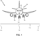
- FIG. 1 depicts an aircraft runway system 100 according to various embodiments.
- Aircraft runway system 100 includes an aircraft 102 and a runway 112.
- Aircraft 102 includes a fuselage 103, a nose wheel 104 coupled to fuselage 103, landing gear wheel 106 coupled to fuselage 103 aft of nose wheel 104, and landing gear wheel 108 coupled to fuselage 103 aft of nose wheel 104 (wherein “aft” means toward the tail end of aircraft 102, and "forward means toward the front of aircraft 102).
- Runway 112 includes sensor 114, sensor 116, and sensor 118.
- sensor 114, sensor 116, and sensor 118 may be, for example, ice sensors positioned on runway 112 to detect whether ice is located on runway 112.
- sensor 114, sensor 116, and sensor 118 may be positioned on runway 112 to determine whether ice is located beneath, for example, nose wheel 104, landing gear wheel 106, and/or landing gear wheel 108.
- sensor 114, sensor 116, and/or sensor 118 located on runway 112 may be triggered to provide runway information, for example, ice location information, to aircraft 102 upon landing of aircraft 102 onto runway 112.
- the information ascertained from sensor 114, sensor 116, and sensor 118 may be provided to aircraft 102 for use during landing of aircraft 102.
- aircraft 102 during landing, aircraft 102 has an actual ground speed that may be determined by, for example, an aircraft ground speed determination system 200 (referring to momentarily and described in detail in FIG. 2 ).
- a benefit of aircraft ground speed determination system 200 is that it is able to utilize nose wheel 104 to determine an actual ground speed of aircraft 102, as opposed to an estimated aircraft ground speed.
- the importance of utilizing nose wheel 104 to determine actual ground speed of aircraft 102 is based in part on the independence of nose wheel 104 from the braking torque and potential slippage associated with measuring the speed of a braking wheel (e.g., measuring the speed of landing gear wheel 106 and landing gear wheel 108 while braking when aircraft 102 is landing on runway 112).
- FIG. 2 is a block diagram showing various system components and data flow of an aircraft ground speed determination system 200 with runway 112.
- Aircraft ground speed determination system 200 includes a nose wheel assembly 207, a landing gear wheel assembly 209, an aircraft ground speed unit 210, an aircraft ground speed display 288, a brake control unit 254, and a reference ground speed system 250.
- nose wheel assembly 207 includes a weight sensor 211, a wheel speed monitor 212, a wheel angle monitor 213, and nose wheel 104. Weight sensor 211, wheel speed monitor 212, and/or wheel angle monitor 213 may be coupled to nose wheel 104 or a component thereof.
- landing gear wheel assembly 209 includes a wheel speed monitor 214 coupled to a landing gear wheel 106 and a wheel speed monitor 215 coupled to a landing gear wheel 108. Brake systems 107, 109 may be coupled to landing gear wheels 106, 108, respectively.
- landing gear wheel assembly may comprise one or more landing gear wheels and/or wheel speed monitors.
- Weight sensor 211 may be any type of sensor capable of detecting weight applied to nose wheel 104 (in response to aircraft 102 landing on a surface, such as runway 112).
- Wheel speed monitor 212, wheel speed monitor 214, and/or wheel speed monitor 215 may be any type of speed sensor known in the art to ascertain the speed of an aircraft wheel.
- wheel angle monitor 213 may be, for example, any type of angle detector known in the art to ascertain the angle of an aircraft wheel during landing and/or taxiing of aircraft 102.
- the angle associated with nose wheel 104 may be represented by a wheel steering angle value 222 and may, for example, be the angle of the nose wheel 104 while aircraft 102 is turning.
- Wheel steering angle value 222 may be referenced from or relative to the base position of nose wheel 104.
- the base position of nose wheel 104 may be defined as the forward position of nose wheel 104 relative to the central axis of the fuselage 103 of aircraft 102, which would cause aircraft 102 to travel in a straight line.
- nose wheel assembly 207 may be electronically coupled to (i.e., in electronic communication with) aircraft ground speed unit 210.
- Nose wheel assembly 207 may transmit a weight signal 231 (reflecting a weight applied to nose wheel 104 detected by weight sensor 211), a wheel speed value 221 (reflecting a wheel speed of nose wheel 104 detected by wheel speed monitor 212), and/or a wheel steering angle value 222 (reflecting an angle of nose wheel 104 relative to the base position of nose wheel 104 detected by wheel angle monitor 213) to aircraft ground speed unit 210.
- Landing gear wheel assembly 209 may be electronically coupled to (i.e., in electronic communication with) reference ground speed system 250.
- Landing gear wheel assembly 209 may transmit a first wheel speed value 223 (reflecting a wheel speed of landing gear wheel 106 detected by wheel speed monitor 214) and/or a second wheel speed value 224 (reflecting a wheel speed of landing gear wheel 108 detected by wheel speed monitor 215). Landing gear wheel assembly 209 is coupled to brake control unit 254 to receive a brake control signal 220.
- aircraft ground speed unit 210 is coupled to reference ground speed system 250 to receive a reference ground speed value 225.
- Aircraft ground speed unit 210 is coupled to aircraft ground speed display 288 to provide an actual aircraft ground speed 227 for visual display.
- Aircraft ground speed unit 210 is coupled to brake control unit 254 to provide a brake adjustment signal 226.
- Aircraft ground speed unit 210, reference ground speed system 250, aircraft ground speed display 288, and brake control unit 254 may include one or more processors and one or more tangible, non-transitory memories and be capable of storing instructions.
- the processor(s) may be a general purpose processor, a digital signal processor (DSP), an application specific integrated circuit (ASIC), a field programmable gate array (FPGA) or other programmable logic device, discrete gate or transistor logic, discrete hardware components, or any combination thereof.
- DSP digital signal processor
- ASIC application specific integrated circuit
- FPGA field programmable gate array
- nose wheel 104 touches down onto runway 112.
- weight sensor 211 may detect a weight being applied to nose wheel 104.
- wheel speed monitor 212 of aircraft ground speed determination system 200 may detect the speed of nose wheel 104 (i.e., wheel speed value 221).
- wheel speed monitor 212 may transmit wheel speed value 221 of nose wheel 104 to aircraft ground speed unit 210.
- Weight sensor 211 may transmit weight signal 231 to aircraft ground speed unit 210 reflecting that a weight is applied to nose wheel 104.
- weight signal 231 may detect simply whether or not there is a weight applied to nose wheel 104 (i.e., nose wheel 104 is on the ground), and/or a duration that the weight is applied to nose wheel 104.
- Reference ground speed system 250 may receive a first wheel speed value 223 and a second wheel speed value 224 from wheel speed monitor 214 and wheel speed monitor 215, respectively. Reference ground speed system 250 may calculate a reference ground speed value 225 based on first wheel speed value 223 and a second wheel speed value 224 (e.g., by calculating an average speed between first wheel speed value 223 and a second wheel speed value 224). Reference ground speed system 250 may transmit reference ground speed value 225 to aircraft ground speed unit 210. In various embodiments, aircraft ground speed unit 210 may determine an actual aircraft ground speed 227 based on wheel speed value 221 and/or reference ground speed value 225, as discussed herein.
- aircraft ground speed unit 210 may determine actual aircraft ground speed 227 by comparing wheel speed value 221 of nose wheel 104 to reference ground speed value 225. In various embodiments, as part of the comparison, aircraft ground speed unit 210 determines if wheel speed value 221 is greater than or equal to reference ground speed value 225. If wheel speed value 221 is greater than or equal to reference ground speed value 225, aircraft ground speed unit 210 may determine actual aircraft ground speed 227 to be equal to wheel speed value 221. In various embodiments, determining that actual aircraft ground speed 227 is equal to wheel speed value 221 may further comprise (or require) determining and/or recognizing by aircraft ground speed unit 210 that a weight is applied to nose wheel 104.
- Such a weight determination may simply require that there is a weight detected applied to nose wheel 104 (e.g., indicating that aircraft 102 has touched down on runway 112), and/or that the weight applied to nose wheel 104 was applied for a predetermined duration (e.g., to make sure the aircraft is not bouncing after touching down onto runway 112).
- determining that actual aircraft ground speed 227 is equal to wheel speed value 221 may further comprise (or require) determining and/or recognizing by aircraft ground speed unit 210 that nose wheel 104 is substantially in the base position (as used in this context only, the term "substantially" means plus or minus three degrees from the base position), as measured by wheel angle monitor 213.
- wheel speed value 221 may not accurately reflect actual aircraft ground speed 227.
- aircraft ground speed unit 210 may determine that actual aircraft ground speed 227 is equal to wheel speed value 221 if wheel speed value 221 is greater than reference ground speed value 225, weight signal 231 reflects a weight applied to nose wheel 104 (and in some cases, for a determined duration), and/or that nose wheel 104 is substantially in the base position.
- aircraft ground speed unit 210 may determine actual aircraft ground speed 227 to be equal to reference ground speed value 225.
- runway 112 is in wireless communication with aircraft 102 via sensor 114, sensor 116, and sensor 118 to provide information to aircraft ground speed unit 210.
- sensor 114, sensor 116, and/or sensor 118 may be in wireless communication with aircraft 102 via runway signals 241, signals 242, and signals 243, respectively.
- Sensor 114, sensor 116, and/or sensor 118 may be positioned to provide an ice location signal/s to aircraft ground speed unit 210 of aircraft 102 indicative of whether ice is located on runway 112 beneath, nose wheel 104, landing gear wheel 106, and/or landing gear wheel 108 of aircraft 102.
- the information provided via, for example, runway signals 241, 242, and 243 may be used by aircraft ground speed unit 210 as, for example, a non-use condition of nose wheel 104.
- a non-use condition may be a condition potentially causing wheel speed value 221 to inaccurately reflect the actual ground speed of aircraft 102. Therefore, a non-use condition may be a condition which prevents aircraft ground speed unit 210 from utilizing wheel speed value 221 in determining actual aircraft ground speed 227.
- nose wheel 104 sliding on ice may cause the wheel speed value 221 to be unequal to the actual ground speed of aircraft 102.
- wheel speed value 221 of nose wheel 104 may not be used by aircraft ground speed unit 210 to determine actual aircraft ground speed 227.
- Other non-use conditions may be a lack of weight applied to nose wheel 104 or a weight applied to nose wheel 104 for an insufficient duration (as detected by weight sensor 211), nose wheel 104 not being disposed substantially in the base position (as detected by wheel angle monitor 213), wheel speed value 221 of nose wheel 104 being about 20% faster than landing gear wheel 106, landing gear wheel 108, and/or reference ground speed value 225 (as used in this context only, "about” means plus or minus 5%) (may indicate a blown tire on a main landing gear wheel), failure of wheel speed monitor 212, and/or the like.
- aircraft ground speed unit 210 may use the reference ground speed value 225 as actual aircraft ground speed 227 (i.e., aircraft ground speed unit 210 may determine that actual aircraft ground speed 227 is equal to the reference ground speed value 225).
- wheel speed value 221 when for example, wheel speed value 221 is less than reference ground speed value 225, wheel speed value 221 may not be used as, or to calculate, actual aircraft ground speed 227 because, for example, nose wheel 104 may have not reached the full speed of aircraft 102 or may be exposed to a non-use condition.
- nose wheel 104 may be affected by non-use conditions such as, for example, ice on runway 112 and/or ice on nose wheel 104.
- the rationale to use reference ground speed value 225 as the actual aircraft ground speed 227 may be based on, for example, the condition of nose wheel 104 or runway 112.
- aircraft ground speed unit 210 may determine whether nose wheel 104 is undergoing the non-use condition by using, for example, an ice sensor located on nose wheel 104 or sensors 114, 116, and/or 118 located on, for example, runway 112.
- the ice sensors located on nose wheel 104 or runway 112 maybe, for example, any type of ice sensor known in the art that is capable of communicating with aircraft 102.
- aircraft ground speed unit 210 may receive a reference ground speed value 225 (step 302) of aircraft 102 from reference ground speed system 250.
- reference ground speed value 225 may be calculated by reference ground speed system 250 based on first wheel speed value 223 from first landing gear wheel 106 and second wheel speed value 224 from second landing gear wheel 108 (e.g., by taking the average of first wheel speed value 223 and second wheel speed value 224).
- aircraft ground speed unit 210 may receive wheel speed value 221 of nose wheel 104 (step 310). In various embodiments, aircraft ground speed unit 210 may compare wheel speed value 221 of nose wheel 104 and reference ground speed value 225 (step 320). Based on the comparison, aircraft ground speed unit 210 may determine actual aircraft ground speed 227 (step 330). In response to wheel speed value 221 of nose wheel 104 being greater than or equal to reference ground speed value 225, aircraft ground speed unit 210 may determine that actual aircraft ground speed 227 is equal (or proportional to) to wheel speed value 221. Conversely, in response to wheel speed value 221 of nose wheel 104 being less than reference ground speed value 225, aircraft ground speed unit 210 may determine that actual aircraft ground speed 227 is equal (or proportional to) to reference ground speed value 225.
- aircraft ground speed unit 210 may receive reference ground speed value 225 (step 302) and wheel speed value 221 of nose wheel 104 (step 310), and compare reference ground speed value 225 and wheel speed value 221 (step 320).
- aircraft ground speed unit 210 may receive wheel steering angle value 222 (step 402) reflecting the angle of nose wheel 104 relative to its base position.
- aircraft ground speed unit 210 may receive weight signal 231 (step 404) indicating whether a weight is applied to nose wheel 104, or the duration for which a weight has been applied to nose wheel 104 (e.g., indicating that, or for how long, aircraft 102 has been in contact with runway 112).
- aircraft ground speed unit 210 may receive a runway signal (step 406) (e.g., runway signal 241, 242, and/or 243), which may indicate the presence of an adverse condition on the runway (e.g., ice, water, or the like, which may cause nose wheel 104 to spin disproportionately to the actual ground speed of aircraft 102).
- aircraft ground speed unit 210 may analyze the received information for a non-use condition (step 408).
- a non-use condition may be detected by aircraft ground speed unit 210 in response to wheel steering angle value 222 reflecting that nose wheel 104 is in a position that is not substantially the base position (i.e., creating an angle relative to the base position that is greater than three degrees).
- a non-use condition may be detected by aircraft ground speed unit 210 in response to weight signal 231 indicating that there is no weight applied to nose wheel 104, and/or a weight has been applied for an insufficient duration.
- a non-use condition may be detected by aircraft ground speed unit 210 in response to a runway signal indicating an adverse condition on runway 112 (e.g., ice, water, or the like).
- a non-use condition may be detected by aircraft ground speed unit 210 in response to wheel speed value 221 being about 20% faster than landing gear wheel 106, landing gear wheel 108, and/or reference ground speed value 225.
- a non-use condition may be detected by aircraft ground speed unit 210 in response to wheel speed monitor malfunctioning.
- aircraft ground speed unit 210 may determine actual aircraft ground speed 227 (step 410) based on the comparison of step 320 and the analysis of 408. If reference ground speed value 225 is greater than wheel speed value 221, aircraft ground speed unit 210 may determine actual aircraft ground speed 227 to be equal to (or proportional to) reference ground speed value 225 (regardless of the detection of a non-use condition). If wheel speed value 221 is greater than or equal to reference ground speed value 225, and no non-use condition is detected by aircraft ground speed unit 210, aircraft ground speed unit 210 may determine actual aircraft ground speed 227 to be equal to (or proportional to) wheel speed value 221.
- aircraft ground speed unit 210 may determine actual aircraft ground speed 227 to be equal to (or proportional to) reference ground speed value 225.
- references to “one embodiment”, “an embodiment”, “various embodiments”, etc. indicate that the embodiment described may include a particular feature, structure, or characteristic, but every embodiment may not necessarily include the particular feature, structure, or characteristic. Moreover, such phrases are not necessarily referring to the same embodiment. Further, when a particular feature, structure, or characteristic is described in connection with an embodiment, it is submitted that it is within the knowledge of one skilled in the art to affect such feature, structure, or characteristic in connection with other embodiments whether or not explicitly described. After reading the description, it will be apparent to one skilled in the relevant art(s) how to implement the disclosure in alternative embodiments.
Landscapes
- Engineering & Computer Science (AREA)
- Physics & Mathematics (AREA)
- General Physics & Mathematics (AREA)
- Transportation (AREA)
- Mechanical Engineering (AREA)
- Aviation & Aerospace Engineering (AREA)
- Traffic Control Systems (AREA)
Abstract
Description
- The present disclosure relates to an aircraft. In particular, the disclosure relates to systems and methods for determining the ground speed of an aircraft.
- A major input to current brake control algorithms for aircrafts is an aircraft reference speed, which may be based on an estimate of what an aircraft wheel speed would be if it was not being braked. Ideally, the aircraft reference speed equals the aircraft ground speed. However, in today's aircraft speed monitoring systems, there is generally not a direct method of determining aircraft ground speed (to use as the aircraft reference speed), because, for example, a wheel speed sensor may measure the speed of the main landing gear wheels while braking during landing. However, during braking, the main landing gear wheels may slip, and thus, the wheel speed measured by the wheel speed sensors may not accurately reflect the ground speed. As a result, the aircraft ground speeds tend to be approximations based on potentially inaccurate wheel speed measurements.
- In various embodiments, a method for determining aircraft ground speed may comprise receiving, by a processor, a reference ground speed value; receiving, by the processor, a wheel speed value of a nose wheel of an aircraft; comparing, by the processor, the wheel speed value of the nose wheel and the reference ground speed value; and/or determining, by the processor, the actual aircraft ground speed based on the reference ground speed value and the wheel speed value. In various embodiments, the actual aircraft ground speed may be determined to be at least one of equal to or proportional to the reference ground speed value in response to the reference ground speed value being greater than the wheel speed value. In various embodiments, the actual aircraft ground speed may be determined to be at least one of equal to or proportional to the wheel speed value in response to the wheel speed value being greater than or equal to the reference ground speed value. In various embodiments, the reference ground speed value may be based on a first wheel speed value from a first landing gear wheel and a second wheel speed value from a second landing gear wheel.
- In various embodiments, the method may further comprise analyzing, by the processor, for a non-use condition prior to the determining the actual aircraft ground speed, wherein a non-use condition is a condition which prevents the processor from utilizing the wheel speed value to determine the actual aircraft ground speed. In various embodiments, the method may further comprise detecting, by the processor, non-existence of the non-use condition in response to the analyzing for the non-use condition, wherein the actual aircraft ground speed is determined to be at least one of equal to or proportional to the wheel speed value in response to the wheel speed value being greater than or equal to the reference ground speed value. In various embodiments, the method may further comprise detecting, by the processor, existence of the non-use condition in response to the analyzing for a non-use condition, wherein the actual aircraft ground speed is determined to be at least one of equal to or proportional to the reference ground speed value in response to the detection of the non-use condition.
- In various embodiments, the method may further comprise receiving, by the processor, at least one of a weight signal, a wheel steering angle value, or a runway signal prior to the analyzing for the non-use condition. In various embodiments, the method may further comprise detecting, by the processor, existence of the non-use condition in response to the analyzing for the non-use condition, wherein the non-use condition may be at least one of the weight signal indicating a lack of weight on the nose wheel, the wheel steering angle value indicating that the nose wheel is not substantially in a base position, or the runway signal indicating an adverse condition on a runway.
- In various embodiments, an aircraft ground speed determination system may comprise a landing gear wheel; a wheel speed monitor coupled to the landing gear wheel; a nose wheel; a nose wheel speed monitor coupled to the nose wheel; a processor in electronic communication with the wheel speed monitor and the nose wheel speed monitor; and/or a tangible, non-transitory memory configured to communicate with the processor, the tangible, non-transitory memory having instructions stored thereon that, in response to execution by the processor, cause the processor to perform operations. The operations may comprise receiving, by the processor, a reference ground speed value; receiving, by the processor, a wheel speed value of the nose wheel of an aircraft; comparing, by the processor, the wheel speed value of the nose wheel and the reference ground speed value; and/or determining, by the processor, an actual aircraft ground speed based on the reference ground speed value and the wheel speed value.
- In various embodiments, the actual aircraft ground speed may be determined to be at least one of equal to or proportional to the reference ground speed value in response to the reference ground speed value being greater than the wheel speed value. In various embodiments, the actual aircraft ground speed may be determined to be at least one of equal to or proportional to the wheel speed value in response to the wheel speed value being greater than or equal to the reference ground speed value. In various embodiments, the reference ground speed value may be based on a first wheel speed value from the landing gear wheel.
- In various embodiments, the operations may further comprise analyzing, by the processor, for a non-use condition prior to the determining the actual aircraft ground speed, wherein a non-use condition is a condition which prevents the processor from utilizing the wheel speed value to determine the actual aircraft ground speed. In various embodiments, the operations may further comprise detecting, by the processor, non-existence of the non-use condition in response to the analyzing for the non-use condition, wherein the actual aircraft ground speed is determined to be at least one of equal to or proportional to the wheel speed value in response to the wheel speed value being greater than or equal to the reference ground speed value. In various embodiments, the operations may further comprise detecting, by the processor, existence of the non-use condition in response to the analyzing for the non-use condition, wherein the actual aircraft ground speed is determined to be at least one of equal to or proportional to the reference ground speed value in response to the detection of the non-use condition.
- In various embodiments, an aircraft may comprise a fuselage; a landing gear wheel coupled to the fuselage; a wheel speed monitor coupled to the landing gear wheel; a nose wheel coupled to the fuselage forward of the landing gear wheel;
- a nose wheel speed monitor coupled to the nose wheel; a processor in electronic communication with the wheel speed monitor and the nose wheel speed monitor; and/or a tangible, non-transitory memory configured to communicate with the processor, the tangible, non-transitory memory having instructions stored thereon that, in response to execution by the processor, cause the processor to perform operations. The operations may comprise receiving, by the processor, a reference ground speed value; receiving, by the processor, a wheel speed value of the nose wheel of the aircraft; comparing, by the processor, the wheel speed value of the nose wheel and the reference ground speed value; and/or determining, by the processor, an actual aircraft ground speed based on the reference ground speed value and the wheel speed value.
- In various embodiments, the actual aircraft ground speed may be determined to be at least one of equal to or proportional to the reference ground speed value in response to the reference ground speed value being greater than the wheel speed value. In various embodiments, the actual aircraft ground speed may be determined to be at least one of equal to or proportional to the wheel speed value in response to the wheel speed value being greater or equal to than the reference ground speed value. In various embodiments, the operations may further comprise analyzing, by the processor, for a non-use condition prior to the determining the actual aircraft ground speed, wherein a non-use condition is a condition which prevents the processor from utilizing the wheel speed value to determine the actual aircraft ground speed.
- The accompanying drawings are included to provide a further understanding of the present disclosure and are incorporated in, and constitute a part of, this specification, illustrate various embodiments, and together with the description, serve to explain the principles of the disclosure.
-
FIG. 1 shows an aircraft runway system, according to various embodiments; -
FIG. 2 is a block diagram showing an aircraft ground speed determination system, in accordance with various embodiments; -
FIG. 3 is a diagram illustrating a process flow for determining aircraft ground speed, in accordance with various embodiments; and -
FIG. 4 is a diagram illustrating another process flow for determining aircraft ground speed, in accordance with various embodiments. - The detailed description of various embodiments herein makes reference to the accompanying drawings, which show various embodiments by way of illustration. While these various embodiments are described in sufficient detail to enable those skilled in the art to practice the disclosure, it should be understood that other embodiments may be realized and that logical, chemical, and mechanical changes may be made without departing from the spirit and scope of the disclosure. Thus, the detailed description herein is presented for purposes of illustration only and not of limitation.
- For example, the steps recited in any of the method or process descriptions may be executed in any order and are not necessarily limited to the order presented. Furthermore, any reference to singular includes plural embodiments, and any reference to more than one component or step may include a singular embodiment or step. Also, any reference to attached, fixed, connected, or the like may include permanent, removable, temporary, partial, full, and/or any other possible attachment option. Additionally, any reference to without contact (or similar phrases) may also include reduced contact or minimal contact.
-
FIG. 1 depicts anaircraft runway system 100 according to various embodiments.Aircraft runway system 100 includes anaircraft 102 and arunway 112.Aircraft 102 includes afuselage 103, anose wheel 104 coupled tofuselage 103,landing gear wheel 106 coupled tofuselage 103 aft ofnose wheel 104, andlanding gear wheel 108 coupled tofuselage 103 aft of nose wheel 104 (wherein "aft" means toward the tail end ofaircraft 102, and "forward means toward the front of aircraft 102). Runway 112 includessensor 114,sensor 116, andsensor 118. In various embodiments,sensor 114,sensor 116, andsensor 118 may be, for example, ice sensors positioned onrunway 112 to detect whether ice is located onrunway 112. In various embodiments, for example,sensor 114,sensor 116, andsensor 118 may be positioned onrunway 112 to determine whether ice is located beneath, for example,nose wheel 104,landing gear wheel 106, and/orlanding gear wheel 108. In various embodiments,sensor 114,sensor 116, and/orsensor 118 located onrunway 112 may be triggered to provide runway information, for example, ice location information, toaircraft 102 upon landing ofaircraft 102 ontorunway 112. The information ascertained fromsensor 114,sensor 116, andsensor 118 may be provided toaircraft 102 for use during landing ofaircraft 102. - In various embodiments, during landing,
aircraft 102 has an actual ground speed that may be determined by, for example, an aircraft ground speed determination system 200 (referring to momentarily and described in detail inFIG. 2 ). A benefit of aircraft groundspeed determination system 200 is that it is able to utilizenose wheel 104 to determine an actual ground speed ofaircraft 102, as opposed to an estimated aircraft ground speed. In various embodiments, the importance of utilizingnose wheel 104 to determine actual ground speed ofaircraft 102 is based in part on the independence ofnose wheel 104 from the braking torque and potential slippage associated with measuring the speed of a braking wheel (e.g., measuring the speed oflanding gear wheel 106 andlanding gear wheel 108 while braking whenaircraft 102 is landing on runway 112). -
FIG. 2 is a block diagram showing various system components and data flow of an aircraft groundspeed determination system 200 withrunway 112. Aircraft groundspeed determination system 200 includes anose wheel assembly 207, a landinggear wheel assembly 209, an aircraftground speed unit 210, an aircraftground speed display 288, a brake control unit 254, and a referenceground speed system 250. - In various embodiments,
nose wheel assembly 207 includes aweight sensor 211, awheel speed monitor 212, awheel angle monitor 213, andnose wheel 104.Weight sensor 211,wheel speed monitor 212, and/orwheel angle monitor 213 may be coupled tonose wheel 104 or a component thereof. In various embodiments, landinggear wheel assembly 209 includes awheel speed monitor 214 coupled to alanding gear wheel 106 and awheel speed monitor 215 coupled to alanding gear wheel 108.Brake systems landing gear wheels Weight sensor 211 may be any type of sensor capable of detecting weight applied to nose wheel 104 (in response toaircraft 102 landing on a surface, such as runway 112).Wheel speed monitor 212,wheel speed monitor 214, and/orwheel speed monitor 215 may be any type of speed sensor known in the art to ascertain the speed of an aircraft wheel. - In various embodiments, wheel angle monitor 213 may be, for example, any type of angle detector known in the art to ascertain the angle of an aircraft wheel during landing and/or taxiing of
aircraft 102. In various embodiments, the angle associated withnose wheel 104 may be represented by a wheelsteering angle value 222 and may, for example, be the angle of thenose wheel 104 whileaircraft 102 is turning. Wheelsteering angle value 222 may be referenced from or relative to the base position ofnose wheel 104. The base position ofnose wheel 104 may be defined as the forward position ofnose wheel 104 relative to the central axis of thefuselage 103 ofaircraft 102, which would causeaircraft 102 to travel in a straight line. - In various embodiments,
nose wheel assembly 207 may be electronically coupled to (i.e., in electronic communication with) aircraftground speed unit 210.Nose wheel assembly 207 may transmit a weight signal 231 (reflecting a weight applied tonose wheel 104 detected by weight sensor 211), a wheel speed value 221 (reflecting a wheel speed ofnose wheel 104 detected by wheel speed monitor 212), and/or a wheel steering angle value 222 (reflecting an angle ofnose wheel 104 relative to the base position ofnose wheel 104 detected by wheel angle monitor 213) to aircraftground speed unit 210. Landinggear wheel assembly 209 may be electronically coupled to (i.e., in electronic communication with) referenceground speed system 250. Landinggear wheel assembly 209 may transmit a first wheel speed value 223 (reflecting a wheel speed oflanding gear wheel 106 detected by wheel speed monitor 214) and/or a second wheel speed value 224 (reflecting a wheel speed oflanding gear wheel 108 detected by wheel speed monitor 215). Landinggear wheel assembly 209 is coupled to brake control unit 254 to receive abrake control signal 220. - In various embodiments, aircraft
ground speed unit 210 is coupled to referenceground speed system 250 to receive a referenceground speed value 225. Aircraftground speed unit 210 is coupled to aircraftground speed display 288 to provide an actualaircraft ground speed 227 for visual display. Aircraftground speed unit 210 is coupled to brake control unit 254 to provide abrake adjustment signal 226. Aircraftground speed unit 210, referenceground speed system 250, aircraftground speed display 288, and brake control unit 254 may include one or more processors and one or more tangible, non-transitory memories and be capable of storing instructions. The processor(s) may be a general purpose processor, a digital signal processor (DSP), an application specific integrated circuit (ASIC), a field programmable gate array (FPGA) or other programmable logic device, discrete gate or transistor logic, discrete hardware components, or any combination thereof. - In various embodiments, with reference to
FIG. 1 andFIG. 2 , during landing ofaircraft 102,nose wheel 104 touches down ontorunway 112. In response,weight sensor 211 may detect a weight being applied tonose wheel 104. Further in response tonose wheel 104 touching down ontorunway 112,wheel speed monitor 212 of aircraft groundspeed determination system 200 may detect the speed of nose wheel 104 (i.e., wheel speed value 221). In various embodiments,wheel speed monitor 212 may transmitwheel speed value 221 ofnose wheel 104 to aircraftground speed unit 210.Weight sensor 211 may transmit weight signal 231 to aircraftground speed unit 210 reflecting that a weight is applied tonose wheel 104. In various embodiments,weight signal 231 may detect simply whether or not there is a weight applied to nose wheel 104 (i.e.,nose wheel 104 is on the ground), and/or a duration that the weight is applied tonose wheel 104. - Reference
ground speed system 250 may receive a firstwheel speed value 223 and a secondwheel speed value 224 fromwheel speed monitor 214 andwheel speed monitor 215, respectively. Referenceground speed system 250 may calculate a referenceground speed value 225 based on firstwheel speed value 223 and a second wheel speed value 224 (e.g., by calculating an average speed between firstwheel speed value 223 and a second wheel speed value 224). Referenceground speed system 250 may transmit referenceground speed value 225 to aircraftground speed unit 210. In various embodiments, aircraftground speed unit 210 may determine an actualaircraft ground speed 227 based onwheel speed value 221 and/or referenceground speed value 225, as discussed herein. - In various embodiments, aircraft
ground speed unit 210 may determine actualaircraft ground speed 227 by comparingwheel speed value 221 ofnose wheel 104 to referenceground speed value 225. In various embodiments, as part of the comparison, aircraftground speed unit 210 determines ifwheel speed value 221 is greater than or equal to referenceground speed value 225. Ifwheel speed value 221 is greater than or equal to referenceground speed value 225, aircraftground speed unit 210 may determine actualaircraft ground speed 227 to be equal towheel speed value 221. In various embodiments, determining that actualaircraft ground speed 227 is equal towheel speed value 221 may further comprise (or require) determining and/or recognizing by aircraftground speed unit 210 that a weight is applied tonose wheel 104. Such a weight determination may simply require that there is a weight detected applied to nose wheel 104 (e.g., indicating thataircraft 102 has touched down on runway 112), and/or that the weight applied tonose wheel 104 was applied for a predetermined duration (e.g., to make sure the aircraft is not bouncing after touching down onto runway 112). In various embodiments, determining that actualaircraft ground speed 227 is equal towheel speed value 221 may further comprise (or require) determining and/or recognizing by aircraftground speed unit 210 thatnose wheel 104 is substantially in the base position (as used in this context only, the term "substantially" means plus or minus three degrees from the base position), as measured bywheel angle monitor 213. Ifnose wheel 104 is not substantially in the base position (causingaircraft 102 to turn),wheel speed value 221 may not accurately reflect actualaircraft ground speed 227. In summary, aircraftground speed unit 210 may determine that actualaircraft ground speed 227 is equal towheel speed value 221 ifwheel speed value 221 is greater than referenceground speed value 225,weight signal 231 reflects a weight applied to nose wheel 104 (and in some cases, for a determined duration), and/or thatnose wheel 104 is substantially in the base position. In various embodiments, ifwheel speed value 221 is less than referenceground speed value 225, no weight is applied to nose wheel 104 (or the weight applied has taken place for an insufficient duration), and/ornose wheel 104 is not substantially in the base position, aircraftground speed unit 210 may determine actualaircraft ground speed 227 to be equal to referenceground speed value 225. - In various embodiments,
runway 112 is in wireless communication withaircraft 102 viasensor 114,sensor 116, andsensor 118 to provide information to aircraftground speed unit 210. In various embodiments, for example,sensor 114,sensor 116, and/orsensor 118, may be in wireless communication withaircraft 102 via runway signals 241, signals 242, and signals 243, respectively.Sensor 114,sensor 116, and/orsensor 118 may be positioned to provide an ice location signal/s to aircraftground speed unit 210 ofaircraft 102 indicative of whether ice is located onrunway 112 beneath,nose wheel 104,landing gear wheel 106, and/orlanding gear wheel 108 ofaircraft 102. - The information provided via, for example, runway signals 241, 242, and 243 may be used by aircraft
ground speed unit 210 as, for example, a non-use condition ofnose wheel 104. A non-use condition may be a condition potentially causingwheel speed value 221 to inaccurately reflect the actual ground speed ofaircraft 102. Therefore, a non-use condition may be a condition which prevents aircraftground speed unit 210 from utilizingwheel speed value 221 in determining actualaircraft ground speed 227. For example,nose wheel 104 sliding on ice (the non-use condition in this example) may cause thewheel speed value 221 to be unequal to the actual ground speed ofaircraft 102. Therefore,wheel speed value 221 ofnose wheel 104, as detected bywheel speed monitor 212, may not be used by aircraftground speed unit 210 to determine actualaircraft ground speed 227. Other non-use conditions may be a lack of weight applied tonose wheel 104 or a weight applied tonose wheel 104 for an insufficient duration (as detected by weight sensor 211),nose wheel 104 not being disposed substantially in the base position (as detected by wheel angle monitor 213),wheel speed value 221 ofnose wheel 104 being about 20% faster thanlanding gear wheel 106,landing gear wheel 108, and/or reference ground speed value 225 (as used in this context only, "about" means plus or minus 5%) (may indicate a blown tire on a main landing gear wheel), failure ofwheel speed monitor 212, and/or the like. - In response to detecting a non-use condition, aircraft
ground speed unit 210 may use the referenceground speed value 225 as actual aircraft ground speed 227 (i.e., aircraftground speed unit 210 may determine that actualaircraft ground speed 227 is equal to the reference ground speed value 225). In various embodiments, when for example,wheel speed value 221 is less than referenceground speed value 225,wheel speed value 221 may not be used as, or to calculate, actualaircraft ground speed 227 because, for example,nose wheel 104 may have not reached the full speed ofaircraft 102 or may be exposed to a non-use condition. For example,nose wheel 104 may be affected by non-use conditions such as, for example, ice onrunway 112 and/or ice onnose wheel 104. Thus, the rationale to use referenceground speed value 225 as the actualaircraft ground speed 227 may be based on, for example, the condition ofnose wheel 104 orrunway 112. - In various embodiments, aircraft
ground speed unit 210 may determine whethernose wheel 104 is undergoing the non-use condition by using, for example, an ice sensor located onnose wheel 104 orsensors runway 112. The ice sensors located onnose wheel 104 orrunway 112 maybe, for example, any type of ice sensor known in the art that is capable of communicating withaircraft 102. - With reference to
FIG. 3 , amethod 300 for determining aircraft ground speed is illustrated according to various embodiments. With combined reference toFIGS. 1-3 , in various embodiments, aircraftground speed unit 210 may receive a reference ground speed value 225 (step 302) ofaircraft 102 from referenceground speed system 250. In various embodiments, referenceground speed value 225 may be calculated by referenceground speed system 250 based on firstwheel speed value 223 from firstlanding gear wheel 106 and secondwheel speed value 224 from second landing gear wheel 108 (e.g., by taking the average of firstwheel speed value 223 and second wheel speed value 224). - In various embodiments, aircraft
ground speed unit 210 may receivewheel speed value 221 of nose wheel 104 (step 310). In various embodiments, aircraftground speed unit 210 may comparewheel speed value 221 ofnose wheel 104 and reference ground speed value 225 (step 320). Based on the comparison, aircraftground speed unit 210 may determine actual aircraft ground speed 227 (step 330). In response towheel speed value 221 ofnose wheel 104 being greater than or equal to referenceground speed value 225, aircraftground speed unit 210 may determine that actualaircraft ground speed 227 is equal (or proportional to) towheel speed value 221. Conversely, in response towheel speed value 221 ofnose wheel 104 being less than referenceground speed value 225, aircraftground speed unit 210 may determine that actualaircraft ground speed 227 is equal (or proportional to) to referenceground speed value 225. - With reference to
FIG. 4 , amethod 400 for determining aircraft ground speed is illustrated, according to various embodiments. With combined reference toFIGS. 1-2 and4 , similar tomethod 300 inFIG. 3 , aircraftground speed unit 210 may receive reference ground speed value 225 (step 302) andwheel speed value 221 of nose wheel 104 (step 310), and compare referenceground speed value 225 and wheel speed value 221 (step 320). In various embodiments, aircraftground speed unit 210 may receive wheel steering angle value 222 (step 402) reflecting the angle ofnose wheel 104 relative to its base position. In various embodiments, aircraftground speed unit 210 may receive weight signal 231 (step 404) indicating whether a weight is applied tonose wheel 104, or the duration for which a weight has been applied to nose wheel 104 (e.g., indicating that, or for how long,aircraft 102 has been in contact with runway 112). In various embodiments, aircraftground speed unit 210 may receive a runway signal (step 406) (e.g.,runway signal 241, 242, and/or 243), which may indicate the presence of an adverse condition on the runway (e.g., ice, water, or the like, which may causenose wheel 104 to spin disproportionately to the actual ground speed of aircraft 102). - In various embodiments, aircraft
ground speed unit 210 may analyze the received information for a non-use condition (step 408). For example, a non-use condition may be detected by aircraftground speed unit 210 in response to wheelsteering angle value 222 reflecting thatnose wheel 104 is in a position that is not substantially the base position (i.e., creating an angle relative to the base position that is greater than three degrees). As another example, a non-use condition may be detected by aircraftground speed unit 210 in response to weight signal 231 indicating that there is no weight applied tonose wheel 104, and/or a weight has been applied for an insufficient duration. As yet another example, a non-use condition may be detected by aircraftground speed unit 210 in response to a runway signal indicating an adverse condition on runway 112 (e.g., ice, water, or the like). As yet another example, a non-use condition may be detected by aircraftground speed unit 210 in response towheel speed value 221 being about 20% faster thanlanding gear wheel 106,landing gear wheel 108, and/or referenceground speed value 225. As yet another example, a non-use condition may be detected by aircraftground speed unit 210 in response to wheel speed monitor malfunctioning. - In various embodiments, aircraft
ground speed unit 210 may determine actual aircraft ground speed 227 (step 410) based on the comparison ofstep 320 and the analysis of 408. If referenceground speed value 225 is greater thanwheel speed value 221, aircraftground speed unit 210 may determine actualaircraft ground speed 227 to be equal to (or proportional to) reference ground speed value 225 (regardless of the detection of a non-use condition). Ifwheel speed value 221 is greater than or equal to referenceground speed value 225, and no non-use condition is detected by aircraftground speed unit 210, aircraftground speed unit 210 may determine actualaircraft ground speed 227 to be equal to (or proportional to)wheel speed value 221. Ifwheel speed value 221 is greater than referenceground speed value 225, and a non-use condition is detected by aircraftground speed unit 210, aircraftground speed unit 210 may determine actualaircraft ground speed 227 to be equal to (or proportional to) referenceground speed value 225. - Benefits, other advantages, and solutions to problems have been described herein with regard to specific embodiments. Furthermore, the connecting lines shown in the various figures contained herein are intended to represent exemplary functional relationships and/or physical couplings between the various elements. It should be noted that many alternative or additional functional relationships or physical connections may be present in a practical system. However, the benefits, advantages, solutions to problems, and any elements that may cause any benefit, advantage, or solution to occur or become more pronounced are not to be construed as critical, required, or essential features or elements of the disclosure. The scope of the disclosure is accordingly to be limited by nothing other than the appended claims, in which reference to an element in the singular is not intended to mean "one and only one" unless explicitly so stated, but rather "one or more." Moreover, where a phrase similar to "at least one of A, B, or C" is used in the claims, it is intended that the phrase be interpreted to mean that A alone may be present in an embodiment, B alone may be present in an embodiment, C alone may be present in an embodiment, or that any combination of the elements A, B and C may be present in a single embodiment; for example, A and B, A and C, B and C, or A and B and C.
- Systems and methods are provided herein. In the detailed description herein, references to "one embodiment", "an embodiment", "various embodiments", etc., indicate that the embodiment described may include a particular feature, structure, or characteristic, but every embodiment may not necessarily include the particular feature, structure, or characteristic. Moreover, such phrases are not necessarily referring to the same embodiment. Further, when a particular feature, structure, or characteristic is described in connection with an embodiment, it is submitted that it is within the knowledge of one skilled in the art to affect such feature, structure, or characteristic in connection with other embodiments whether or not explicitly described. After reading the description, it will be apparent to one skilled in the relevant art(s) how to implement the disclosure in alternative embodiments.
- Furthermore, no element, component, or method step in the present disclosure is intended to be dedicated to the public regardless of whether the element, component, or method step is explicitly recited in the claims. As used herein, the terms "comprises", "comprising", or any other variation thereof, are intended to cover a non-exclusive inclusion, such that a process, method, article, or apparatus that comprises a list of elements does not include only those elements but may include other elements not expressly listed or inherent to such process, method, article, or apparatus.
Claims (15)
- A method of determining an actual aircraft ground speed, comprising:receiving, by a processor, a reference ground speed value;receiving, by the processor, a wheel speed value of a nose wheel of an aircraft;comparing, by the processor, the wheel speed value of the nose wheel and the reference ground speed value; anddetermining, by the processor, the actual aircraft ground speed based on the reference ground speed value and the wheel speed value.
- The method of claim 1, wherein the actual aircraft ground speed is determined to be at least one of equal to or proportional to the reference ground speed value in response to the reference ground speed value being greater than the wheel speed value.
- The method of claim 1, wherein the actual aircraft ground speed is determined to be at least one of equal to or proportional to the wheel speed value in response to the wheel speed value being greater than or equal to the reference ground speed value.
- The method of claim 1, wherein the reference ground speed value is based on a first wheel speed value from a first landing gear wheel and a second wheel speed value from a second landing gear wheel.
- The method of any preceding claim, further comprising analyzing, by the processor, for a non-use condition prior to the determining the actual aircraft ground speed, wherein the non-use condition is a condition which prevents the processor from utilizing the wheel speed value to determine the actual aircraft ground speed.
- The method of claim 5, further comprising detecting, by the processor, non-existence of the non-use condition in response to the analyzing for the non-use condition, wherein the actual aircraft ground speed is determined to be at least one of equal to or proportional to the wheel speed value in response to the wheel speed value being greater than or equal to the reference ground speed value; or
further comprising detecting, by the processor, existence of the non-use condition in response to the analyzing for the non-use condition, wherein the actual aircraft ground speed is determined to be at least one of equal to or proportional to the reference ground speed value in response to the detection of the non-use condition. - The method of claim 5, further comprising receiving, by the processor, at least one of a weight signal, a wheel steering angle value, or a runway signal prior to the analyzing for the non-use condition, and preferably further comprising detecting, by the processor, existence of the non-use condition in response to the analyzing for the non-use condition, wherein the non-use condition is at least one of the weight signal indicating a lack of weight on the nose wheel, the wheel steering angle value indicating that the nose wheel is not substantially in a base position, or the runway signal indicating an adverse condition on a runway.
- An aircraft ground speed determination system (200), comprising:a landing gear wheel (106);a wheel speed monitor (215) coupled to the landing gear wheel (108);a nose wheel (104);a nose wheel speed monitor (212) coupled to the nose wheel (104);a processor in electronic communication with the wheel speed monitor and the nose wheel speed monitor; anda tangible, non-transitory memory configured to communicate with the processor, the tangible, non-transitory memory having instructions stored thereon that, in response to execution by the processor, cause the processor to perform operations comprising:receiving, by the processor, a reference ground speed value;receiving, by the processor, a wheel speed value of the nose wheel of an aircraft;comparing, by the processor, the wheel speed value of the nose wheel and the reference ground speed value; anddetermining, by the processor, an actual aircraft ground speed based on the reference ground speed value and the wheel speed value.
- The aircraft ground speed determination system of claim 8, wherein the actual aircraft ground speed is determined to be at least one of equal to or proportional to the reference ground speed value in response to the reference ground speed value being greater than the wheel speed value.
- The aircraft ground speed determination system of claim 8, wherein the actual aircraft ground speed is determined to be at least one of equal to or proportional to the wheel speed value in response to the wheel speed value being greater than or equal to the reference ground speed value.
- The aircraft ground speed determination system of any of claims 8 to 10, wherein the reference ground speed value is based on a first wheel speed value from the landing gear wheel.
- The aircraft ground speed determination system of any of claims 8 to 11, wherein the operations further comprise analyzing, by the processor, for a non-use condition prior to the determining the actual aircraft ground speed, wherein the non-use condition is a condition which prevents the processor from utilizing the wheel speed value to determine the actual aircraft ground speed.
- The aircraft ground speed determination system of claim 12, wherein the operations further comprise detecting, by the processor, non-existence of the non-use condition in response to the analyzing for the non-use condition, wherein the actual aircraft ground speed is determined to be at least one of equal to or proportional to the wheel speed value in response to the wheel speed value being greater than or equal to the reference ground speed value, and preferably wherein the operations further comprise detecting, by the processor, existence of the non-use condition in response to the analyzing for the non-use condition, wherein the actual aircraft ground speed is determined to be at least one of equal to or proportional to the reference ground speed value in response to the detection of the non-use condition.
- An aircraft (102), comprising:a fuselage;a landing gear wheel (106) coupled to the fuselage;a wheel speed monitor (215) coupled to the landing gear wheel (108);a nose wheel (104) coupled to the fuselage forward of the landing gear wheel (106);a nose wheel speed monitor (212) coupled to the nose wheel (104);a processor in electronic communication with the wheel speed monitor and the nose wheel speed monitor; anda tangible, non-transitory memory configured to communicate with the processor, the tangible, non-transitory memory having instructions stored thereon that, in response to execution by the processor, cause the processor to perform operations comprising:receiving, by the processor, a reference ground speed value;receiving, by the processor, a wheel speed value of the nose wheel of the aircraft;comparing, by the processor, the wheel speed value of the nose wheel and the reference ground speed value; anddetermining, by the processor, an actual aircraft ground speed based on the reference ground speed value and the wheel speed value.
- The aircraft of claim 14, wherein the actual aircraft ground speed is determined to be at least one of equal to or proportional to the reference ground speed value in response to the reference ground speed value being greater than the wheel speed value; or
wherein the actual aircraft ground speed is determined to be at least one of equal to or proportional to the wheel speed value in response to the wheel speed value being greater than or equal to the reference ground speed value; or
wherein the operations further comprise analyzing, by the processor, for a non-use condition prior to the determining the actual aircraft ground speed, wherein the non-use condition is a condition which prevents the processor from utilizing the wheel speed value to determine the actual aircraft ground speed.
Applications Claiming Priority (1)
| Application Number | Priority Date | Filing Date | Title |
|---|---|---|---|
| US15/787,611 US10618669B2 (en) | 2017-10-18 | 2017-10-18 | Method of determining aircraft ground speed |
Publications (2)
| Publication Number | Publication Date |
|---|---|
| EP3474021A1 true EP3474021A1 (en) | 2019-04-24 |
| EP3474021B1 EP3474021B1 (en) | 2021-03-31 |
Family
ID=63857718
Family Applications (1)
| Application Number | Title | Priority Date | Filing Date |
|---|---|---|---|
| EP18200239.4A Active EP3474021B1 (en) | 2017-10-18 | 2018-10-12 | Method of determining aircraft ground speed |
Country Status (2)
| Country | Link |
|---|---|
| US (1) | US10618669B2 (en) |
| EP (1) | EP3474021B1 (en) |
Families Citing this family (4)
| Publication number | Priority date | Publication date | Assignee | Title |
|---|---|---|---|---|
| FR3089494B1 (en) * | 2018-12-05 | 2022-04-08 | Safran Landing Systems | Method for controlling the speed of a device for driving the wheels of an aircraft in rotation |
| CN113759276B (en) * | 2021-01-05 | 2024-05-17 | 西安京东天鸿科技有限公司 | Grounding diagnosis method and device |
| GB2616077A (en) | 2022-02-28 | 2023-08-30 | Airbus Operations Ltd | Aircraft steering angle determination |
| GB2616078A (en) * | 2022-02-28 | 2023-08-30 | Airbus Operations Ltd | Aircraft steering angle determination |
Citations (3)
| Publication number | Priority date | Publication date | Assignee | Title |
|---|---|---|---|---|
| EP2821301A1 (en) * | 2013-07-02 | 2015-01-07 | Goodrich Corporation | System and method for detecting an on ground condition of an aircraft |
| US20170057624A1 (en) * | 2015-08-28 | 2017-03-02 | Honeywell International Inc. | Aircraft landing gear wheel-drive system |
| US20170089939A1 (en) * | 2015-09-30 | 2017-03-30 | Kawasaki Jukogyo Kabushiki Kaisha | Ground speed detection device for vehicle |
Family Cites Families (9)
| Publication number | Priority date | Publication date | Assignee | Title |
|---|---|---|---|---|
| US3520575A (en) | 1968-07-12 | 1970-07-14 | Goodyear Tire & Rubber | Automatic brake control system |
| US4410153A (en) * | 1978-06-29 | 1983-10-18 | The Boeing Company | Brake control system for providing brake release signals |
| US9280155B2 (en) | 2011-12-02 | 2016-03-08 | Borealis Technical Limited | Aircraft ground travel traction control system and method |
| US9428161B2 (en) * | 2013-11-19 | 2016-08-30 | Goodrich Corporation | Brake control initiation using tire runway friction map data |
| US9139293B2 (en) | 2014-01-22 | 2015-09-22 | The Boeing Company | Optimized real-time antiskid control initialization for travel surfaces as a function of wheel spinup |
| US9457896B2 (en) | 2014-01-24 | 2016-10-04 | Honeywell International Inc. | Electric taxi system with speed control (ETSSC) |
| EP3178738A1 (en) * | 2015-12-07 | 2017-06-14 | Safran Landing Systems UK Limited | Fully electric speed-proportional nose wheel steering system for an aircraft |
| GB2545217A (en) * | 2015-12-09 | 2017-06-14 | Jaguar Land Rover Ltd | Control system for a motor vehicle and method |
| US10940939B2 (en) * | 2017-12-11 | 2021-03-09 | Textron Innovations, Inc. | Ground spoiler control architecture for aircraft |
-
2017
- 2017-10-18 US US15/787,611 patent/US10618669B2/en active Active
-
2018
- 2018-10-12 EP EP18200239.4A patent/EP3474021B1/en active Active
Patent Citations (3)
| Publication number | Priority date | Publication date | Assignee | Title |
|---|---|---|---|---|
| EP2821301A1 (en) * | 2013-07-02 | 2015-01-07 | Goodrich Corporation | System and method for detecting an on ground condition of an aircraft |
| US20170057624A1 (en) * | 2015-08-28 | 2017-03-02 | Honeywell International Inc. | Aircraft landing gear wheel-drive system |
| US20170089939A1 (en) * | 2015-09-30 | 2017-03-30 | Kawasaki Jukogyo Kabushiki Kaisha | Ground speed detection device for vehicle |
Also Published As
| Publication number | Publication date |
|---|---|
| EP3474021B1 (en) | 2021-03-31 |
| US10618669B2 (en) | 2020-04-14 |
| US20190112070A1 (en) | 2019-04-18 |
Similar Documents
| Publication | Publication Date | Title |
|---|---|---|
| EP3474021B1 (en) | Method of determining aircraft ground speed | |
| CN108216168B (en) | Train skidding or idle running detection method and device | |
| US10352827B2 (en) | Tire contact state estimation method | |
| US9842439B2 (en) | Air data probe contamination monitor | |
| CN104931007B (en) | Method and device for automatically estimating parameters relating to the flight of an aircraft | |
| US20170106706A1 (en) | Method and arrangement for locating the installation position of wheels in a vehicle | |
| US8965657B2 (en) | System and method for detecting an on ground condition of an aircraft | |
| JP6750482B2 (en) | Tire lateral hydro performance evaluation system | |
| CN108364372B (en) | Vehicle driving state detection method and device | |
| EP4220186B1 (en) | Aircraft freestream data systems | |
| CN111976395A (en) | Automatic positioning using a system mounted to the tire | |
| CN106660417A (en) | Tire pneumatic pressure detector | |
| EP3015294B1 (en) | Enhanced brake control system with wheel mounted position sensor | |
| US8712629B2 (en) | Method and device for detecting the dysfunction of a gas pressure sensor in a vehicle tire | |
| US7675434B2 (en) | Method and device for detecting, on the ground, the obstruction of a pressure tap of a static pressure sensor of an aircraft | |
| US12345639B2 (en) | System for determining a wheel-rail adhesion value for a railway vehicle | |
| US9213334B2 (en) | Runway traction estimation and reporting system | |
| KR102610734B1 (en) | Apparatus and method for monitoring tire pressure of vehicle | |
| CN110461628A (en) | Method for correcting measured pressure in tires | |
| US8352187B2 (en) | Method and system for monitoring parameters of an aircraft | |
| CA2448836A1 (en) | Process and device for detecting failures of pressure sensors in aircraft air data computers | |
| EP3462178B1 (en) | Low profile air data architecture | |
| KR101544886B1 (en) | Method and System for Monitoring Pressure of Tire | |
| CN105835636B (en) | Method and apparatus for detecting disengagement of a sensor device mounted on a vehicle wheel | |
| US20230382167A1 (en) | Method of determining a left-or-right side installation position of a trailer wheel |
Legal Events
| Date | Code | Title | Description |
|---|---|---|---|
| PUAI | Public reference made under article 153(3) epc to a published international application that has entered the european phase |
Free format text: ORIGINAL CODE: 0009012 |
|
| STAA | Information on the status of an ep patent application or granted ep patent |
Free format text: STATUS: THE APPLICATION HAS BEEN PUBLISHED |
|
| AK | Designated contracting states |
Kind code of ref document: A1 Designated state(s): AL AT BE BG CH CY CZ DE DK EE ES FI FR GB GR HR HU IE IS IT LI LT LU LV MC MK MT NL NO PL PT RO RS SE SI SK SM TR |
|
| AX | Request for extension of the european patent |
Extension state: BA ME |
|
| STAA | Information on the status of an ep patent application or granted ep patent |
Free format text: STATUS: REQUEST FOR EXAMINATION WAS MADE |
|
| STAA | Information on the status of an ep patent application or granted ep patent |
Free format text: STATUS: EXAMINATION IS IN PROGRESS |
|
| 17P | Request for examination filed |
Effective date: 20191024 |
|
| RBV | Designated contracting states (corrected) |
Designated state(s): AL AT BE BG CH CY CZ DE DK EE ES FI FR GB GR HR HU IE IS IT LI LT LU LV MC MK MT NL NO PL PT RO RS SE SI SK SM TR |
|
| 17Q | First examination report despatched |
Effective date: 20191121 |
|
| GRAP | Despatch of communication of intention to grant a patent |
Free format text: ORIGINAL CODE: EPIDOSNIGR1 |
|
| STAA | Information on the status of an ep patent application or granted ep patent |
Free format text: STATUS: GRANT OF PATENT IS INTENDED |
|
| RIC1 | Information provided on ipc code assigned before grant |
Ipc: G01P 3/00 20060101ALI20201019BHEP Ipc: B60T 8/17 20060101ALI20201019BHEP Ipc: G01P 21/02 20060101ALI20201019BHEP Ipc: G01P 3/56 20060101AFI20201019BHEP Ipc: B60T 8/171 20060101ALI20201019BHEP |
|
| INTG | Intention to grant announced |
Effective date: 20201103 |
|
| GRAS | Grant fee paid |
Free format text: ORIGINAL CODE: EPIDOSNIGR3 |
|
| GRAA | (expected) grant |
Free format text: ORIGINAL CODE: 0009210 |
|
| STAA | Information on the status of an ep patent application or granted ep patent |
Free format text: STATUS: THE PATENT HAS BEEN GRANTED |
|
| AK | Designated contracting states |
Kind code of ref document: B1 Designated state(s): AL AT BE BG CH CY CZ DE DK EE ES FI FR GB GR HR HU IE IS IT LI LT LU LV MC MK MT NL NO PL PT RO RS SE SI SK SM TR |
|
| REG | Reference to a national code |
Ref country code: GB Ref legal event code: FG4D Ref country code: CH Ref legal event code: EP |
|
| REG | Reference to a national code |
Ref country code: AT Ref legal event code: REF Ref document number: 1377534 Country of ref document: AT Kind code of ref document: T Effective date: 20210415 |
|
| REG | Reference to a national code |
Ref country code: DE Ref legal event code: R096 Ref document number: 602018014654 Country of ref document: DE |
|
| REG | Reference to a national code |
Ref country code: IE Ref legal event code: FG4D |
|
| REG | Reference to a national code |
Ref country code: LT Ref legal event code: MG9D |
|
| PG25 | Lapsed in a contracting state [announced via postgrant information from national office to epo] |
Ref country code: FI Free format text: LAPSE BECAUSE OF FAILURE TO SUBMIT A TRANSLATION OF THE DESCRIPTION OR TO PAY THE FEE WITHIN THE PRESCRIBED TIME-LIMIT Effective date: 20210331 Ref country code: HR Free format text: LAPSE BECAUSE OF FAILURE TO SUBMIT A TRANSLATION OF THE DESCRIPTION OR TO PAY THE FEE WITHIN THE PRESCRIBED TIME-LIMIT Effective date: 20210331 Ref country code: BG Free format text: LAPSE BECAUSE OF FAILURE TO SUBMIT A TRANSLATION OF THE DESCRIPTION OR TO PAY THE FEE WITHIN THE PRESCRIBED TIME-LIMIT Effective date: 20210630 Ref country code: NO Free format text: LAPSE BECAUSE OF FAILURE TO SUBMIT A TRANSLATION OF THE DESCRIPTION OR TO PAY THE FEE WITHIN THE PRESCRIBED TIME-LIMIT Effective date: 20210630 |
|
| PG25 | Lapsed in a contracting state [announced via postgrant information from national office to epo] |
Ref country code: SE Free format text: LAPSE BECAUSE OF FAILURE TO SUBMIT A TRANSLATION OF THE DESCRIPTION OR TO PAY THE FEE WITHIN THE PRESCRIBED TIME-LIMIT Effective date: 20210331 Ref country code: RS Free format text: LAPSE BECAUSE OF FAILURE TO SUBMIT A TRANSLATION OF THE DESCRIPTION OR TO PAY THE FEE WITHIN THE PRESCRIBED TIME-LIMIT Effective date: 20210331 Ref country code: LV Free format text: LAPSE BECAUSE OF FAILURE TO SUBMIT A TRANSLATION OF THE DESCRIPTION OR TO PAY THE FEE WITHIN THE PRESCRIBED TIME-LIMIT Effective date: 20210331 |
|
| REG | Reference to a national code |
Ref country code: NL Ref legal event code: MP Effective date: 20210331 |
|
| REG | Reference to a national code |
Ref country code: AT Ref legal event code: MK05 Ref document number: 1377534 Country of ref document: AT Kind code of ref document: T Effective date: 20210331 |
|
| PG25 | Lapsed in a contracting state [announced via postgrant information from national office to epo] |
Ref country code: AT Free format text: LAPSE BECAUSE OF FAILURE TO SUBMIT A TRANSLATION OF THE DESCRIPTION OR TO PAY THE FEE WITHIN THE PRESCRIBED TIME-LIMIT Effective date: 20210331 Ref country code: NL Free format text: LAPSE BECAUSE OF FAILURE TO SUBMIT A TRANSLATION OF THE DESCRIPTION OR TO PAY THE FEE WITHIN THE PRESCRIBED TIME-LIMIT Effective date: 20210331 Ref country code: SM Free format text: LAPSE BECAUSE OF FAILURE TO SUBMIT A TRANSLATION OF THE DESCRIPTION OR TO PAY THE FEE WITHIN THE PRESCRIBED TIME-LIMIT Effective date: 20210331 Ref country code: EE Free format text: LAPSE BECAUSE OF FAILURE TO SUBMIT A TRANSLATION OF THE DESCRIPTION OR TO PAY THE FEE WITHIN THE PRESCRIBED TIME-LIMIT Effective date: 20210331 Ref country code: CZ Free format text: LAPSE BECAUSE OF FAILURE TO SUBMIT A TRANSLATION OF THE DESCRIPTION OR TO PAY THE FEE WITHIN THE PRESCRIBED TIME-LIMIT Effective date: 20210331 Ref country code: LT Free format text: LAPSE BECAUSE OF FAILURE TO SUBMIT A TRANSLATION OF THE DESCRIPTION OR TO PAY THE FEE WITHIN THE PRESCRIBED TIME-LIMIT Effective date: 20210331 |
|
| PG25 | Lapsed in a contracting state [announced via postgrant information from national office to epo] |
Ref country code: SK Free format text: LAPSE BECAUSE OF FAILURE TO SUBMIT A TRANSLATION OF THE DESCRIPTION OR TO PAY THE FEE WITHIN THE PRESCRIBED TIME-LIMIT Effective date: 20210331 Ref country code: RO Free format text: LAPSE BECAUSE OF FAILURE TO SUBMIT A TRANSLATION OF THE DESCRIPTION OR TO PAY THE FEE WITHIN THE PRESCRIBED TIME-LIMIT Effective date: 20210331 Ref country code: PL Free format text: LAPSE BECAUSE OF FAILURE TO SUBMIT A TRANSLATION OF THE DESCRIPTION OR TO PAY THE FEE WITHIN THE PRESCRIBED TIME-LIMIT Effective date: 20210331 Ref country code: PT Free format text: LAPSE BECAUSE OF FAILURE TO SUBMIT A TRANSLATION OF THE DESCRIPTION OR TO PAY THE FEE WITHIN THE PRESCRIBED TIME-LIMIT Effective date: 20210802 Ref country code: IS Free format text: LAPSE BECAUSE OF FAILURE TO SUBMIT A TRANSLATION OF THE DESCRIPTION OR TO PAY THE FEE WITHIN THE PRESCRIBED TIME-LIMIT Effective date: 20210731 |
|
| REG | Reference to a national code |
Ref country code: DE Ref legal event code: R097 Ref document number: 602018014654 Country of ref document: DE |
|
| PG25 | Lapsed in a contracting state [announced via postgrant information from national office to epo] |
Ref country code: ES Free format text: LAPSE BECAUSE OF FAILURE TO SUBMIT A TRANSLATION OF THE DESCRIPTION OR TO PAY THE FEE WITHIN THE PRESCRIBED TIME-LIMIT Effective date: 20210331 Ref country code: AL Free format text: LAPSE BECAUSE OF FAILURE TO SUBMIT A TRANSLATION OF THE DESCRIPTION OR TO PAY THE FEE WITHIN THE PRESCRIBED TIME-LIMIT Effective date: 20210331 Ref country code: DK Free format text: LAPSE BECAUSE OF FAILURE TO SUBMIT A TRANSLATION OF THE DESCRIPTION OR TO PAY THE FEE WITHIN THE PRESCRIBED TIME-LIMIT Effective date: 20210331 |
|
| PLBE | No opposition filed within time limit |
Free format text: ORIGINAL CODE: 0009261 |
|
| STAA | Information on the status of an ep patent application or granted ep patent |
Free format text: STATUS: NO OPPOSITION FILED WITHIN TIME LIMIT |
|
| 26N | No opposition filed |
Effective date: 20220104 |
|
| REG | Reference to a national code |
Ref country code: DE Ref legal event code: R119 Ref document number: 602018014654 Country of ref document: DE |
|
| REG | Reference to a national code |
Ref country code: CH Ref legal event code: PL |
|
| PG25 | Lapsed in a contracting state [announced via postgrant information from national office to epo] |
Ref country code: IS Free format text: LAPSE BECAUSE OF FAILURE TO SUBMIT A TRANSLATION OF THE DESCRIPTION OR TO PAY THE FEE WITHIN THE PRESCRIBED TIME-LIMIT Effective date: 20210731 |
|
| REG | Reference to a national code |
Ref country code: BE Ref legal event code: MM Effective date: 20211031 |
|
| PG25 | Lapsed in a contracting state [announced via postgrant information from national office to epo] |
Ref country code: MC Free format text: LAPSE BECAUSE OF FAILURE TO SUBMIT A TRANSLATION OF THE DESCRIPTION OR TO PAY THE FEE WITHIN THE PRESCRIBED TIME-LIMIT Effective date: 20210331 |
|
| PG25 | Lapsed in a contracting state [announced via postgrant information from national office to epo] |
Ref country code: LU Free format text: LAPSE BECAUSE OF NON-PAYMENT OF DUE FEES Effective date: 20211012 Ref country code: IT Free format text: LAPSE BECAUSE OF FAILURE TO SUBMIT A TRANSLATION OF THE DESCRIPTION OR TO PAY THE FEE WITHIN THE PRESCRIBED TIME-LIMIT Effective date: 20210331 Ref country code: DE Free format text: LAPSE BECAUSE OF NON-PAYMENT OF DUE FEES Effective date: 20220503 Ref country code: BE Free format text: LAPSE BECAUSE OF NON-PAYMENT OF DUE FEES Effective date: 20211031 |
|
| PG25 | Lapsed in a contracting state [announced via postgrant information from national office to epo] |
Ref country code: LI Free format text: LAPSE BECAUSE OF NON-PAYMENT OF DUE FEES Effective date: 20211031 Ref country code: CH Free format text: LAPSE BECAUSE OF NON-PAYMENT OF DUE FEES Effective date: 20211031 |
|
| PG25 | Lapsed in a contracting state [announced via postgrant information from national office to epo] |
Ref country code: IE Free format text: LAPSE BECAUSE OF NON-PAYMENT OF DUE FEES Effective date: 20211012 |
|
| P01 | Opt-out of the competence of the unified patent court (upc) registered |
Effective date: 20230521 |
|
| PG25 | Lapsed in a contracting state [announced via postgrant information from national office to epo] |
Ref country code: CY Free format text: LAPSE BECAUSE OF FAILURE TO SUBMIT A TRANSLATION OF THE DESCRIPTION OR TO PAY THE FEE WITHIN THE PRESCRIBED TIME-LIMIT Effective date: 20210331 |
|
| PG25 | Lapsed in a contracting state [announced via postgrant information from national office to epo] |
Ref country code: HU Free format text: LAPSE BECAUSE OF FAILURE TO SUBMIT A TRANSLATION OF THE DESCRIPTION OR TO PAY THE FEE WITHIN THE PRESCRIBED TIME-LIMIT; INVALID AB INITIO Effective date: 20181012 Ref country code: GR Free format text: LAPSE BECAUSE OF FAILURE TO SUBMIT A TRANSLATION OF THE DESCRIPTION OR TO PAY THE FEE WITHIN THE PRESCRIBED TIME-LIMIT Effective date: 20210331 |
|
| PG25 | Lapsed in a contracting state [announced via postgrant information from national office to epo] |
Ref country code: MK Free format text: LAPSE BECAUSE OF FAILURE TO SUBMIT A TRANSLATION OF THE DESCRIPTION OR TO PAY THE FEE WITHIN THE PRESCRIBED TIME-LIMIT Effective date: 20210331 |
|
| PG25 | Lapsed in a contracting state [announced via postgrant information from national office to epo] |
Ref country code: TR Free format text: LAPSE BECAUSE OF FAILURE TO SUBMIT A TRANSLATION OF THE DESCRIPTION OR TO PAY THE FEE WITHIN THE PRESCRIBED TIME-LIMIT Effective date: 20210331 |
|
| PG25 | Lapsed in a contracting state [announced via postgrant information from national office to epo] |
Ref country code: MT Free format text: LAPSE BECAUSE OF FAILURE TO SUBMIT A TRANSLATION OF THE DESCRIPTION OR TO PAY THE FEE WITHIN THE PRESCRIBED TIME-LIMIT Effective date: 20210331 |
|
| PGFP | Annual fee paid to national office [announced via postgrant information from national office to epo] |
Ref country code: GB Payment date: 20250923 Year of fee payment: 8 |
|
| PGFP | Annual fee paid to national office [announced via postgrant information from national office to epo] |
Ref country code: FR Payment date: 20250924 Year of fee payment: 8 |