EP3473996B1 - System and method for calculating margin of friction coefficient at tire contact patch - Google Patents
System and method for calculating margin of friction coefficient at tire contact patch Download PDFInfo
- Publication number
- EP3473996B1 EP3473996B1 EP18198196.0A EP18198196A EP3473996B1 EP 3473996 B1 EP3473996 B1 EP 3473996B1 EP 18198196 A EP18198196 A EP 18198196A EP 3473996 B1 EP3473996 B1 EP 3473996B1
- Authority
- EP
- European Patent Office
- Prior art keywords
- friction coefficient
- pressure
- contact patch
- margin
- tire
- Prior art date
- Legal status (The legal status is an assumption and is not a legal conclusion. Google has not performed a legal analysis and makes no representation as to the accuracy of the status listed.)
- Active
Links
- 238000000034 method Methods 0.000 title claims description 24
- 238000005259 measurement Methods 0.000 claims description 55
- 238000009826 distribution Methods 0.000 claims description 36
- 230000015654 memory Effects 0.000 description 8
- 238000012545 processing Methods 0.000 description 7
- 238000001514 detection method Methods 0.000 description 6
- 230000000694 effects Effects 0.000 description 4
- 238000005096 rolling process Methods 0.000 description 2
- 230000001133 acceleration Effects 0.000 description 1
- 238000013459 approach Methods 0.000 description 1
- 238000011161 development Methods 0.000 description 1
- 230000018109 developmental process Effects 0.000 description 1
- 238000010586 diagram Methods 0.000 description 1
- 230000006870 function Effects 0.000 description 1
- 238000000691 measurement method Methods 0.000 description 1
Images


Classifications
-
- G—PHYSICS
- G01—MEASURING; TESTING
- G01N—INVESTIGATING OR ANALYSING MATERIALS BY DETERMINING THEIR CHEMICAL OR PHYSICAL PROPERTIES
- G01N19/00—Investigating materials by mechanical methods
- G01N19/02—Measuring coefficient of friction between materials
-
- G—PHYSICS
- G01—MEASURING; TESTING
- G01M—TESTING STATIC OR DYNAMIC BALANCE OF MACHINES OR STRUCTURES; TESTING OF STRUCTURES OR APPARATUS, NOT OTHERWISE PROVIDED FOR
- G01M17/00—Testing of vehicles
- G01M17/007—Wheeled or endless-tracked vehicles
- G01M17/02—Tyres
- G01M17/022—Tyres the tyre co-operating with rotatable rolls
-
- B—PERFORMING OPERATIONS; TRANSPORTING
- B60—VEHICLES IN GENERAL
- B60T—VEHICLE BRAKE CONTROL SYSTEMS OR PARTS THEREOF; BRAKE CONTROL SYSTEMS OR PARTS THEREOF, IN GENERAL; ARRANGEMENT OF BRAKING ELEMENTS ON VEHICLES IN GENERAL; PORTABLE DEVICES FOR PREVENTING UNWANTED MOVEMENT OF VEHICLES; VEHICLE MODIFICATIONS TO FACILITATE COOLING OF BRAKES
- B60T8/00—Arrangements for adjusting wheel-braking force to meet varying vehicular or ground-surface conditions, e.g. limiting or varying distribution of braking force
- B60T8/17—Using electrical or electronic regulation means to control braking
- B60T8/172—Determining control parameters used in the regulation, e.g. by calculations involving measured or detected parameters
-
- B—PERFORMING OPERATIONS; TRANSPORTING
- B60—VEHICLES IN GENERAL
- B60W—CONJOINT CONTROL OF VEHICLE SUB-UNITS OF DIFFERENT TYPE OR DIFFERENT FUNCTION; CONTROL SYSTEMS SPECIALLY ADAPTED FOR HYBRID VEHICLES; ROAD VEHICLE DRIVE CONTROL SYSTEMS FOR PURPOSES NOT RELATED TO THE CONTROL OF A PARTICULAR SUB-UNIT
- B60W40/00—Estimation or calculation of non-directly measurable driving parameters for road vehicle drive control systems not related to the control of a particular sub unit, e.g. by using mathematical models
- B60W40/02—Estimation or calculation of non-directly measurable driving parameters for road vehicle drive control systems not related to the control of a particular sub unit, e.g. by using mathematical models related to ambient conditions
- B60W40/06—Road conditions
- B60W40/068—Road friction coefficient
-
- G—PHYSICS
- G01—MEASURING; TESTING
- G01M—TESTING STATIC OR DYNAMIC BALANCE OF MACHINES OR STRUCTURES; TESTING OF STRUCTURES OR APPARATUS, NOT OTHERWISE PROVIDED FOR
- G01M17/00—Testing of vehicles
- G01M17/007—Wheeled or endless-tracked vehicles
- G01M17/02—Tyres
-
- G—PHYSICS
- G07—CHECKING-DEVICES
- G07C—TIME OR ATTENDANCE REGISTERS; REGISTERING OR INDICATING THE WORKING OF MACHINES; GENERATING RANDOM NUMBERS; VOTING OR LOTTERY APPARATUS; ARRANGEMENTS, SYSTEMS OR APPARATUS FOR CHECKING NOT PROVIDED FOR ELSEWHERE
- G07C5/00—Registering or indicating the working of vehicles
- G07C5/08—Registering or indicating performance data other than driving, working, idle, or waiting time, with or without registering driving, working, idle or waiting time
- G07C5/0808—Diagnosing performance data
-
- B—PERFORMING OPERATIONS; TRANSPORTING
- B29—WORKING OF PLASTICS; WORKING OF SUBSTANCES IN A PLASTIC STATE IN GENERAL
- B29D—PRODUCING PARTICULAR ARTICLES FROM PLASTICS OR FROM SUBSTANCES IN A PLASTIC STATE
- B29D30/00—Producing pneumatic or solid tyres or parts thereof
- B29D30/0061—Accessories, details or auxiliary operations not otherwise provided for
Definitions
- the present disclosure is related to a system and method for calculating a degree of underutilized potential improvement at a tire contact patch.
- Japanese Patent Application Publication Kokai JP 2014-21012 A discloses a method in which a tire is brought into contact with a rotating drum equipped with a force sensor, the rotating drum and the tire are made to rotate together, the sensor and the tire are brought into contact, and the sensor is used to measure the ground contact characteristics of the tire.
- a three-axis force sensor is employed as the force sensor, tire contact patch pressure, shear stress in the tire width direction, and shear stress in the tire circumferential direction are measured.
- tire contact patch pressure is measured.
- shear stress in the tire width direction is measured.
- shear stress in the tire circumferential direction is measured.
- Japanese Patent Application Publication Kokai JP H09-26382 A discloses a method in which the measurement apparatus is not a three-axis force sensor but in which a tire is brought into contact with a planar stage equipped with the measurement apparatus, and ground contact characteristics are measured as the tire is made to roll over the measurement apparatus.
- the present disclosure was conceived in view of such problems, it being an object thereof to provide a system and method for calculating the margin of the friction coefficient at a tire contact patch.
- the present disclosure employs means as described below.
- the margin of the friction coefficient is thus calculated, meaning that the greater the margin the more room there is for improvement. This therefore makes it possible for a designer to intuitively know which locations have room for improvement based on the magnitude of the margin.
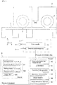
- a tire ground contact characteristics measurement device has a travel surface 1 for allowing travel by tire T thereon, a tire drive apparatus 2 which causes tire T to be brought into contact with and to roll on travel surface 1, a force sensor 3 which is provided on travel surface 1, and a measurement controller 4 which is implemented by means of a computer.
- the travel surface 1 appears rectangular as seen in plan view, being a flat surface.
- the force sensor 3 has a detection region, force being measured in the form of a single measurement point at the detection region when tire T comes in contact with the detection region.
- the force sensor 3 is a three-axis force sensor and is capable of measuring circumferential direction shear pressure Px [kPa], width direction shear pressure Py [kPa], and contact patch pressure Pz [kPa] at the location at which contact with the tire occurs.
- a plurality of force sensors 3 are arrayed along prescribed direction(s) in array-like fashion so as to constitute sensor group(s).
- the tire drive apparatus 2 causes tire T to be pressed against and approach travel surface 1, sliding movement along the direction MD of travel of the tire causing the tire T to be made to roll.
- the location at which contact between the force sensor 3 and the tire T occurs is capable of being adjusted by changing the location at which rolling of the tire T is initiated.
- the measurement controller 4 has a tire drive controller 40 which controls driving of the tire drive apparatus 2, and a detection results storage unit 41 which stores results of detection by the force sensor 3 following receipt of a signal by the sensor.
- a system 5 calculates a margin of the friction coefficient at a tire contact patch based on a pressure distribution data measured by the ground contact characteristics measurement device. More specifically, system 5 has a pressure distribution data acquisition unit 50, ⁇ calculator 51, associated data generator 52, maximum value identifier 53, and a margin calculator 54. The system 5 may further have a margin information output unit 55. These respective units 50 through 55 are implemented in cooperative fashion in software and hardware as a result of execution of previously stored ⁇ margin calculation processing routine(s) by CPU(s) at computer(s) equipped with CPU(s), memory or memories, various interface(s), and so forth.
- the pressure distribution data acquisition unit 50 shown in FIG. 1 acquires pressure distribution data D1 measured by the ground contact characteristics measurement device.
- pressure distribution data D1 there are a plurality of measurement points for which forces along three axes (circumferential direction pressure Px, width direction pressure Py, and contact patch pressure Pz) have been measured.
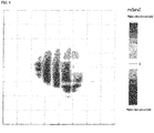
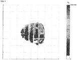
- width direction pressure Py By plotting width direction pressure Py for all measurement points among the pressure distribution data D1, it is possible to obtain a graph of the distribution of width direction pressure Py as shown in FIG. 4 .
- the vertical axis is the tire circumferential direction CD
- the horizontal axis is the tire width direction WD.
- Magnitude of pressure is indicated by color as shown in the legend inset at the graph.
- a graph of the distribution of circumferential direction pressure Px is not shown in the drawings.
- the pressure distribution data D1 shown here is the result of measurements made during cornering sufficient to produce an acceleration of 0.4 G consistent with a slip angle of approximately 1.1° acting on a tire of size 205/60R15, under a load of 3.64 [kN], with an internal pressure of 230 [kPa], and having a basic groove pattern in which there were lateral grooves and sipes.
- the ⁇ calculator 51 shown in FIG. 1 calculates friction coefficients ⁇ exhibited at respective measurement points based on the forces along three axes (Px, Py, and Pz) measured at those measurement points. Results of calculation of friction coefficients ⁇ are stored in memory as working data D2. Friction coefficients ⁇ are calculated for all measurement points. Friction coefficient ⁇ can be calculated by dividing the vector sum of circumferential direction pressure Px and width direction pressure Py by contact patch pressure Pz.
- the associated data generator 52 shown in FIG. 1 generates associated data D3 for a plurality of situations based on the single situation represented by the contact patch pressure Pz and the friction coefficient ⁇ exhibited at contact patch pressure Pz at a single measurement point.
- Associated data D3 is data in which contact patch pressure Pz and the maximum friction coefficient ⁇ MAX that is capable of being exhibited at contact patch pressure Pz are mutually linked.
- the associated data D3 which is generated is stored in memory.
- a table may be provided that stores a plurality of data pairs, each data pair consisting of a contact patch pressure Pz and a maximum friction coefficient ⁇ MAX which is linked thereto, such that a search may be carried out when a contact patch pressure Pz value is input thereto so as to permit the maximum friction coefficient ⁇ MAX that is linked therewith to be output therefrom.
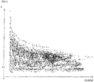
- each measurement point is represented by a single point in which friction coefficient ⁇ is plotted on the vertical axis and contact patch pressure Pz is plotted on the horizontal axis; and as shown in FIG. 7 , contact patch pressure Pz is varied, a plurality of maximum friction coefficients ⁇ MAX are extracted, and an approximation formula is used to approximate the plurality of maximum friction coefficients ⁇ MAX .
- a plurality of measurement points were divided by contact patch pressure Pz into sets of prescribed range (10 kPa in the present embodiment), and for each (10 kPa) set, a prescribed number (two in the present embodiment) of values were extracted therefrom in order from those having the highest values of friction coefficient ⁇ .
- the least-squares method was employed. This is merely one example of data processing, there being no limitation with respect thereto.
- the maximum value identifier 53 shown in FIG. 1 identifies maximum friction coefficients ⁇ MAX corresponding to contact patch pressures Pz at respective measurement points based on associated data D3.
- the maximum friction coefficients ⁇ MAX which are calculated are stored in memory as working data D2.
- the margin calculator 54 shown in FIG. 1 calculates the margin of the friction coefficient ⁇ R , which is the difference between the maximum friction coefficient ⁇ MAX and the friction coefficient ⁇ [ ⁇ MAX - ⁇ ], at each of the respective measurement points.
- the margins of the friction coefficient ⁇ R which are calculated are stored in memory as working data D2.
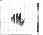
- the vertical axis is the tire circumferential direction CD
- the horizontal axis is the tire width direction WD.
- Magnitude of the margin of the friction coefficient ⁇ R is indicated by color as shown in the legend inset at the graph.
- the margin information output unit 55 shown in FIG. 1 outputs information related to the margin of the friction coefficient ⁇ R .
- One example of the form that such output might take is a graph of the distribution of the margin of the friction coefficient ⁇ R as shown in FIG. 9 .
- At least one of the graph of distribution of friction coefficient ⁇ which is exhibited that is shown in FIG. 5 and the graph of the distribution of maximum friction coefficient ⁇ MAX that is shown in FIG. 8 may be output.
- this might be displayed on a display or image data might be output to an external location.
- margin information output unit 55 may display only locations for which the margin ⁇ R is at least some prescribed threshold value.
- pressure distribution data acquisition unit 50 acquires pressure distribution data D1 at which there are a plurality of measurement points for which forces along three axes (Px, Py, and Pz) have been measured by force sensor 3 provided at the road that is contacted by the tire.
- the ⁇ calculator 51 calculates friction coefficients ⁇ based on the forces along three axes (Px, Py, and Pz) at the respective measurement points.
- the associated data generator 52 generates associated data D3, linking contact patch pressure Pz and the maximum friction coefficient ⁇ MAX that is capable of being exhibited at contact patch pressure Pz, for a plurality of situations based on the single situation represented by the contact patch pressure Pz and the friction coefficient ⁇ exhibited at contact patch pressure Pz at a single measurement point.
- the maximum value identifier 53 identifies maximum friction coefficients ⁇ MAX corresponding to contact patch pressures Pz at respective measurement points based on associated data D3.
- the margin calculator 54 calculates the margin of the friction coefficient ⁇ R , which is the difference between the maximum friction coefficient ⁇ MAX and the friction coefficient ⁇ [ ⁇ MAX - ⁇ ], at each of the respective measurement points.
- the margin information output unit 55 outputs information related to the margin of the friction coefficient ⁇ R .
- the method for calculating a margin of a friction coefficient at a tire contact patch in accordance with the present embodiment is a method executed by a computer and comprises:
- the margin of the friction coefficient ⁇ R is thus calculated, meaning that the greater the margin ⁇ R the more room there is for improvement. This therefore makes it possible for a designer to intuitively know which locations have room for improvement based on the magnitude of the margin ⁇ R .
- the method of the present embodiment comprises outputting information related to the margin of the friction coefficient ⁇ R (ST6).
- the system of the present embodiment is provided with margin information output unit 55 which outputs information related to the margin of the friction coefficient ⁇ R .
- Program(s) in accordance with the present embodiment cause computer(s) to execute the respective steps that make up the foregoing method.
- Friction coefficient ⁇ varies in correspondence to contact patch pressure Pz and sliding speed. By causing the tire to roll very slowly it is therefore possible to ignore sliding speed, making it possible to improve precision. Conversely, where the tire does not roll very slowly but has an appreciable sliding speed, while precision will be reduced in correspondence to the magnitude thereof, it will still be possible to calculate the margin of the friction coefficient ⁇ R , for which reason the method of the present disclosure will be effective.
- the units 50 through 55 shown in FIG. 1 are implemented by causing CPU(s) of computer(s) to execute prescribed program(s), the respective units may be constituted from dedicated memory or memories and/or dedicated circuitry.
- the respective units 50 through 55 are implemented in the context of a single computer, the respective units 50 through 55 may be implemented in distributed fashion by a plurality of computers. That is, the foregoing method may be executed by one processor or by a plurality of processors.
Description
- The present disclosure is related to a system and method for calculating a degree of underutilized potential improvement at a tire contact patch.
- As a method for measuring the ground contact characteristics of a rolling tire, Japanese Patent Application Publication Kokai
JP 2014-21012 A - A three-axis force sensor is employed as the force sensor, tire contact patch pressure, shear stress in the tire width direction, and shear stress in the tire circumferential direction are measured. There is a description to the effect that the interrelationship among the distributions of the forces along these three axes makes it possible to calculate the friction coefficient µ at any arbitrary location, making it possible to know the distribution of the friction coefficient µ.
- As another measurement method, Japanese Patent Application Publication Kokai
JP H09-26382 A - At Japanese Patent Application Publication Kokai
JP 2014-21012 A US 2005/159874 A1 , there is a description to the effect that it is possible to know the distribution of the friction coefficient µ of a tire. However, even if might allow one to see the distribution of the friction coefficient µ, it still does not allow a tire designer to instantly know which locations within the overall tire contact patch have room for improvement. - While it is preferred for any given contact patch pressure that the maximum friction coefficient µMAX that is capable of being exhibited actually be exhibited, there are situations in which the friction coefficient µ that is actually exhibited is less than the maximum friction coefficient µMAX. In such situations, because there will be a difference between the maximum friction coefficient and the friction coefficient, and because this difference will represent the margin of the friction coefficient, it is fair to say that there is room for improvement at such location(s).
- The present disclosure was conceived in view of such problems, it being an object thereof to provide a system and method for calculating the margin of the friction coefficient at a tire contact patch.
- To solve the foregoing problem, the present disclosure employs means as described below.
- In other words, according to the present disclosure, there is provided a method for calculating a margin of a friction coefficient at a tire contact patch according to
claim 1. - According to the invention, there is also provided a system for calculating a margin of a friction coefficient at a tire contact patch according to
claim 3. Advantageous further developments of the method and the system are specified in subclaims. - The margin of the friction coefficient is thus calculated, meaning that the greater the margin the more room there is for improvement. This therefore makes it possible for a designer to intuitively know which locations have room for improvement based on the magnitude of the margin.
-
- FIG. 1
- Block diagram and side view showing system for calculating margin of friction coefficient and a tire ground contact characteristics measurement device in accordance with the present disclosure
- FIG. 2
- Flowchart showing routine for processing to calculate margin of µ which is executed by system
- FIG. 3
- Graph of distribution of contact patch pressure Pz
- FIG. 4
- Graph of distribution of width direction pressure Py
- FIG. 5
- Graph of distribution of friction coefficient µ
- FIG. 6]
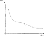
- Graph on which friction coefficient µ and contact patch pressure Pz are plotted
- FIG. 7
- Drawing to assist in description related to associated data
- FIG. 8
- Graph of distribution of maximum friction coefficient µMAX
- FIG. 9
- Graph of distribution of margin of friction coefficient µR
- Below, an embodiment in accordance with the present disclosure is described with reference to the drawings.
- As shown in
FIG. 1 , a tire ground contact characteristics measurement device has atravel surface 1 for allowing travel by tire T thereon, atire drive apparatus 2 which causes tire T to be brought into contact with and to roll ontravel surface 1, aforce sensor 3 which is provided ontravel surface 1, and ameasurement controller 4 which is implemented by means of a computer. - The
travel surface 1 appears rectangular as seen in plan view, being a flat surface. Theforce sensor 3 has a detection region, force being measured in the form of a single measurement point at the detection region when tire T comes in contact with the detection region. Theforce sensor 3 is a three-axis force sensor and is capable of measuring circumferential direction shear pressure Px [kPa], width direction shear pressure Py [kPa], and contact patch pressure Pz [kPa] at the location at which contact with the tire occurs. A plurality offorce sensors 3 are arrayed along prescribed direction(s) in array-like fashion so as to constitute sensor group(s). - As shown in
FIG. 1 , thetire drive apparatus 2 causes tire T to be pressed against and approachtravel surface 1, sliding movement along the direction MD of travel of the tire causing the tire T to be made to roll. The location at which contact between theforce sensor 3 and the tire T occurs is capable of being adjusted by changing the location at which rolling of the tire T is initiated. - The
measurement controller 4 has atire drive controller 40 which controls driving of thetire drive apparatus 2, and a detectionresults storage unit 41 which stores results of detection by theforce sensor 3 following receipt of a signal by the sensor. - As shown in
FIG. 1 , asystem 5 calculates a margin of the friction coefficient at a tire contact patch based on a pressure distribution data measured by the ground contact characteristics measurement device. More specifically,system 5 has a pressure distributiondata acquisition unit 50,µ calculator 51, associateddata generator 52,maximum value identifier 53, and amargin calculator 54. Thesystem 5 may further have a margininformation output unit 55. Theserespective units 50 through 55 are implemented in cooperative fashion in software and hardware as a result of execution of previously stored µ margin calculation processing routine(s) by CPU(s) at computer(s) equipped with CPU(s), memory or memories, various interface(s), and so forth. - The pressure distribution
data acquisition unit 50 shown inFIG. 1 acquires pressure distribution data D1 measured by the ground contact characteristics measurement device. At pressure distribution data D1, there are a plurality of measurement points for which forces along three axes (circumferential direction pressure Px, width direction pressure Py, and contact patch pressure Pz) have been measured. - There are N measurement points. By plotting contact patch pressure Pz for all measurement points among the pressure distribution data D1, it is possible to obtain a graph of the distribution of contact patch pressure Pz as shown in
FIG. 3 . - By plotting width direction pressure Py for all measurement points among the pressure distribution data D1, it is possible to obtain a graph of the distribution of width direction pressure Py as shown in
FIG. 4 . AtFIG. 3 andFIG. 4 , the vertical axis is the tire circumferential direction CD, and the horizontal axis is the tire width direction WD. Magnitude of pressure is indicated by color as shown in the legend inset at the graph. Here, note that a graph of the distribution of circumferential direction pressure Px is not shown in the drawings. - Here, while a graph showing distribution of circumferential direction pressure Px is not shown in the drawings, note that a graph of the distribution of circumferential direction pressure Px may be produced in similar fashion as has been shown for width direction pressure Py and contact patch pressure Pz.
- Note that the pressure distribution data D1 shown here is the result of measurements made during cornering sufficient to produce an acceleration of 0.4 G consistent with a slip angle of approximately 1.1° acting on a tire of size 205/60R15, under a load of 3.64 [kN], with an internal pressure of 230 [kPa], and having a basic groove pattern in which there were lateral grooves and sipes.
- The
µ calculator 51 shown inFIG. 1 calculates friction coefficients µ exhibited at respective measurement points based on the forces along three axes (Px, Py, and Pz) measured at those measurement points. Results of calculation of friction coefficients µ are stored in memory as working data D2. Friction coefficients µ are calculated for all measurement points. Friction coefficient µ can be calculated by dividing the vector sum of circumferential direction pressure Px and width direction pressure Py by contact patch pressure Pz. - By plotting the calculated friction coefficients µ, it is possible to obtain a graph of the distribution of friction coefficient µ as shown in
FIG. 5 . AtFIG. 5 , the vertical axis is the tire circumferential direction CD, and the horizontal axis is the tire width direction WD. Magnitude of friction coefficient µ is indicated by color as shown in the legend inset at the graph. - The associated
data generator 52 shown inFIG. 1 generates associated data D3 for a plurality of situations based on the single situation represented by the contact patch pressure Pz and the friction coefficient µ exhibited at contact patch pressure Pz at a single measurement point. Associated data D3 is data in which contact patch pressure Pz and the maximum friction coefficient µMAX that is capable of being exhibited at contact patch pressure Pz are mutually linked. - The associated data D3 which is generated is stored in memory. Whereas associated data D3 in the present embodiment is the formula "µMAX = f(Pz)" which takes the argument contact patch pressure Pz and outputs maximum friction coefficient µMAX as a function thereof, there is no limitation with respect thereto. For example, a table may be provided that stores a plurality of data pairs, each data pair consisting of a contact patch pressure Pz and a maximum friction coefficient µMAX which is linked thereto, such that a search may be carried out when a contact patch pressure Pz value is input thereto so as to permit the maximum friction coefficient µMAX that is linked therewith to be output therefrom.
- And in the event that the contact patch pressure Pz value which is input thereto is not present in the table, interpolation might be carried out so as to permit the interpolated maximum friction coefficient µMAX to be output therefrom. Or associated data may be implemented by any of various other methods.
- In accordance with the present embodiment, as shown in
FIG. 6 , each measurement point is represented by a single point in which friction coefficient µ is plotted on the vertical axis and contact patch pressure Pz is plotted on the horizontal axis; and as shown inFIG. 7 , contact patch pressure Pz is varied, a plurality of maximum friction coefficients µMAX are extracted, and an approximation formula is used to approximate the plurality of maximum friction coefficients µMAX. - Specifically, taking a plurality of friction coefficients µ which correspond to a contact patch pressure of interest, processing in which a prescribed number of values are extracted therefrom in order from those having the highest values is carried out a plurality of times, the foregoing contact patch pressure of interest being varied each time, and a formula is used to generate a best-fit approximation formula for the extracted friction coefficients.
- More specifically, a plurality of measurement points were divided by contact patch pressure Pz into sets of prescribed range (10 kPa in the present embodiment), and for each (10 kPa) set, a prescribed number (two in the present embodiment) of values were extracted therefrom in order from those having the highest values of friction coefficient µ.
- As shown in
FIG. 7 , a prescribed formula (fifth-order formula in the present embodiment) was used to obtain a best-fit approximation formula "µMAX = f(Pz)" for the extracted values. In obtaining the best-fit approximation formula, the least-squares method was employed. This is merely one example of data processing, there being no limitation with respect thereto. - The
maximum value identifier 53 shown inFIG. 1 identifies maximum friction coefficients µMAX corresponding to contact patch pressures Pz at respective measurement points based on associated data D3. Approximation formula "µMAX = f(Pz)" which is associated data D3 is used to calculate maximum friction coefficient µMAX for all measurement points for which a contact patch pressure Pz exists. The maximum friction coefficients µMAX which are calculated are stored in memory as working data D2. - By plotting the calculated maximum friction coefficients µMAX, it is possible to obtain a graph of the distribution of maximum friction coefficient µMAX as shown in
FIG. 8 . AtFIG. 8 , the vertical axis is the tire circumferential direction CD, and the horizontal axis is the tire width direction WD. Magnitude of maximum friction coefficient µMAX is indicated by color as shown in the legend inset at the graph - The
margin calculator 54 shown inFIG. 1 calculates the margin of the friction coefficient µR, which is the difference between the maximum friction coefficient µMAX and the friction coefficient µ [µMAX - µ], at each of the respective measurement points. The margins of the friction coefficient µR which are calculated are stored in memory as working data D2. - By plotting the calculated margins of the friction coefficient µR, it is possible to obtain a graph of the distribution of the margin of the friction coefficient µR as shown in
FIG. 9 . AtFIG. 9 , the vertical axis is the tire circumferential direction CD, and the horizontal axis is the tire width direction WD. Magnitude of the margin of the friction coefficient µR is indicated by color as shown in the legend inset at the graph. - The margin
information output unit 55 shown inFIG. 1 outputs information related to the margin of the friction coefficient µR. One example of the form that such output might take is a graph of the distribution of the margin of the friction coefficient µR as shown inFIG. 9 . - Furthermore, in addition to the graph of the distribution of the margin of the friction coefficient µR, at least one of the graph of distribution of friction coefficient µ which is exhibited that is shown in
FIG. 5 and the graph of the distribution of maximum friction coefficient µMAX that is shown inFIG. 8 may be output. - As the manner in which output is carried out, this might be displayed on a display or image data might be output to an external location.
- Furthermore, as information related to the margin of the friction coefficient the µR, margin
information output unit 55 may display only locations for which the margin µR is at least some prescribed threshold value. - Operation of the foregoing system will be described with reference to
FIGS. 1 and2 . - First, at step ST1, pressure distribution
data acquisition unit 50 acquires pressure distribution data D1 at which there are a plurality of measurement points for which forces along three axes (Px, Py, and Pz) have been measured byforce sensor 3 provided at the road that is contacted by the tire. - Next, at step ST2, the
µ calculator 51 calculates friction coefficients µ based on the forces along three axes (Px, Py, and Pz) at the respective measurement points. - Next, at step ST3, the associated
data generator 52 generates associated data D3, linking contact patch pressure Pz and the maximum friction coefficient µMAX that is capable of being exhibited at contact patch pressure Pz, for a plurality of situations based on the single situation represented by the contact patch pressure Pz and the friction coefficient µ exhibited at contact patch pressure Pz at a single measurement point. - Next, at step ST4, the
maximum value identifier 53 identifies maximum friction coefficients µMAX corresponding to contact patch pressures Pz at respective measurement points based on associated data D3. - Next, at step ST5, the
margin calculator 54 calculates the margin of the friction coefficient µR, which is the difference between the maximum friction coefficient µMAX and the friction coefficient µ [µMAX - µ], at each of the respective measurement points. - Next, at step ST6, the margin
information output unit 55 outputs information related to the margin of the friction coefficient µR. - As described above, the method for calculating a margin of a friction coefficient at a tire contact patch in accordance with the present embodiment is a method executed by a computer and comprises:
- acquiring pressure distribution data D1 at which there are a plurality of measurement points for which forces along three axes (Px, Py, and Pz) have been measured by
force sensor 3 provided at a road that is contacted by a tire (ST1); - calculating friction coefficients µ based on forces along three axes (Px, Py, and Pz) at the respective measurement points (ST2);
- generating associated data D3, linking contact patch pressure Pz and the maximum friction coefficient µMAX that is capable of being exhibited at contact patch pressure Pz, for a plurality of situations based on the single situation represented by the contact patch pressure Pz and the friction coefficient µ exhibited at contact patch pressure Pz at a single measurement point (ST3);
- identifying maximum friction coefficients µMAX corresponding to contact patch pressures Pz at respective measurement points based on associated data D3 (ST4); and
- calculating a margin of the friction coefficient µR, which is the difference between the maximum friction coefficient µMAX and the friction coefficient µ [µMAX - µ], at each of the respective measurement points (ST5).
- The system for calculating a margin of a friction coefficient at a tire contact patch in accordance with the present embodiment is provided with:
- pressure distribution
data acquisition unit 50 which acquires pressure distribution data D1 at which there are a plurality of measurement points for which forces along three axes (Px, Py, and Pz) have been measured byforce sensor 3 provided at a road that is contacted by a tire; -
µ calculator 51 which calculates friction coefficients µ based on forces along three axes (Px, Py, and Pz) at the respective measurement points; - associated
data generator 52 which generates associated data D3, at which contact patch pressure Pz and the maximum friction coefficient µMAX that is capable of being exhibited at contact patch pressure Pz are mutually linked, for a plurality of situations based on the single situation represented by the contact patch pressure Pz and the friction coefficient µ exhibited at contact patch pressure Pz at a single measurement point; -
maximum value identifier 53 which identifies maximum friction coefficients µMAX corresponding to contact patch pressures Pz at respective measurement points based on associated data D3; and -
margin calculator 54 which calculates a margin of the friction coefficient µR, which is the difference between the maximum friction coefficient µMAX and the friction coefficient µ [µMAX - µ], at each of the respective measurement points. - The margin of the friction coefficient µR is thus calculated, meaning that the greater the margin µR the more room there is for improvement. This therefore makes it possible for a designer to intuitively know which locations have room for improvement based on the magnitude of the margin µR.
- The method of the present embodiment comprises outputting information related to the margin of the friction coefficient µR (ST6).
- The system of the present embodiment is provided with margin
information output unit 55 which outputs information related to the margin of the friction coefficient µR. - As a result of adoption of such constitution, it is possible for a designer to intuitively know the locations at which there is room for improvement.
- Program(s) in accordance with the present embodiment cause computer(s) to execute the respective steps that make up the foregoing method.
- The operation and effects provided by the foregoing method can also be obtained as a result of execution of such program(s). In other words, it might be said that such program(s) make use of the foregoing method.
- The foregoing measurement device carries out measurements while causing the tire to roll very slowly. Friction coefficient µ varies in correspondence to contact patch pressure Pz and sliding speed. By causing the tire to roll very slowly it is therefore possible to ignore sliding speed, making it possible to improve precision. Conversely, where the tire does not roll very slowly but has an appreciable sliding speed, while precision will be reduced in correspondence to the magnitude thereof, it will still be possible to calculate the margin of the friction coefficient µR, for which reason the method of the present disclosure will be effective.
- While embodiments in accordance with the present disclosure have been described above with reference to the drawings, it should be understood that the specific constitution thereof is not limited to these embodiments. The scope of the present disclosure is as indicated by the claims.
- Except where the output of previous processing is used in subsequent processing, the order of execution of operations, procedures, steps, stages, and other such respective processing taking place, for example, in the context of the device(s), system(s), program(s), and method(s) indicated in the claims, specification, and drawings may be implemented in any desired order. Although words such as "first," "next," and so forth may be employed for convenience of description when explaining the flow of activities occurring in the context of the claims, specification, and drawings, this should not be understood to imply that execution must be carried out in that order.
- For example, whereas the
units 50 through 55 shown inFIG. 1 are implemented by causing CPU(s) of computer(s) to execute prescribed program(s), the respective units may be constituted from dedicated memory or memories and/or dedicated circuitry. - At the system of the present embodiment, whereas the
respective units 50 through 55 are implemented in the context of a single computer, therespective units 50 through 55 may be implemented in distributed fashion by a plurality of computers. That is, the foregoing method may be executed by one processor or by a plurality of processors. -
- 1
- travel surface
- 2
- drive apparatus
- 3
- force sensor
- 4
- measurement roller
- 5
- system
- 40
- tire drive controller
- 41
- detection results storage unit
- 50
- pressure distribution data acquisition unit
- 51
- µ calculator
- 52
- associated data generator
- 53
- maximum value identifier
- 54
- margin calculator
- 55
- margin information output unit
Claims (4)
- A method for calculating a margin of a friction coefficient (µr) at a tire contact patch comprising:- measuring, at each of a plurality of measurements points, circumferential direction shear pressure (Px), width direction shear pressure (Py), and contact patch pressure (Pz) along three axes (x, y, z) using a force sensor (3) provided at a road that is contacted by a tire;- calculating, at each of the plurality of measurement points, a friction coefficient (µ) based on the measured circumferential direction shear pressure (Px), the measured width direction shear pressure (Py), and the measured contact patch pressure (Pz) at the respective measurement point;- correlating the calculated friction coefficient (µ) over the corresponding measured contact patch pressure (Pz) for each of the plurality of measurement points;- extracting, for each measured contact patch pressure (Pz), the corresponding maximum friction coefficient (µmax) that is capable of being exhibited at the respective contact patch pressure (Pz); and- calculating, at each of the plurality of measurement points, a margin of the friction coefficient (µr), which is a difference between the maximum friction coefficient (µmax) and the calculated friction coefficient (µ) at the respective measurement point.
- The method according to claim 1
further comprising outputting (ST6) information related to the margin of the friction coefficient (µr). - A system for calculating a margin of a friction coefficient (µr) at a tire contact patch according to the method of claim 1, the system comprising:- a pressure distribution data acquisition unit (50) which is adapted to acquire a circumferential direction shear pressure (Px), a width direction shear pressure (Py), and a contact patch pressure (Pz) measured, at each of a plurality of measurements points, along three axes (x, y, z) using a force sensor (3) provided at a road that is contacted by a tire;- a µ calculator (51) which is adapted to calculate, at each of the plurality of measurement points, a friction coefficient (µ) based on the measured circumferential direction shear pressure (Px), the measured width direction shear pressure (Py), and the measured contact patch pressure (Pz) at the respective measurement point;- an associated data generator (52) which is adapted to correlate the calculated friction coefficient (µ) over the corresponding measured contact patch pressure (Pz) for each of the plurality of measurement points;- a maximum value identifier (53) which is adapted to extract, for each measured contact patch pressure (Pz), the corresponding maximum friction coefficient (µmax) that is capable of being exhibited at the respective contact patch pressure (Pz); and- a margin calculator (54) which is adapted to calculate, at each of the plurality of measurement points, a margin of the friction coefficient (µ), which is a difference between the maximum friction coefficient (µmax) and the calculated friction coefficient (µ) at the respective measurement point.
- The system according to claim 3,
further comprising a margin information output unit (55) which is adapted to output information related to the margin of the friction coefficient (µr).
Applications Claiming Priority (1)
| Application Number | Priority Date | Filing Date | Title |
|---|---|---|---|
| JP2017200832A JP6899752B2 (en) | 2017-10-17 | 2017-10-17 | Methods, systems and programs for calculating the coefficient of friction margin on the tire tread |
Publications (2)
| Publication Number | Publication Date |
|---|---|
| EP3473996A1 EP3473996A1 (en) | 2019-04-24 |
| EP3473996B1 true EP3473996B1 (en) | 2021-04-07 |
Family
ID=63722218
Family Applications (1)
| Application Number | Title | Priority Date | Filing Date |
|---|---|---|---|
| EP18198196.0A Active EP3473996B1 (en) | 2017-10-17 | 2018-10-02 | System and method for calculating margin of friction coefficient at tire contact patch |
Country Status (4)
| Country | Link |
|---|---|
| US (1) | US10955333B2 (en) |
| EP (1) | EP3473996B1 (en) |
| JP (1) | JP6899752B2 (en) |
| CN (1) | CN109668744B (en) |
Families Citing this family (5)
| Publication number | Priority date | Publication date | Assignee | Title |
|---|---|---|---|---|
| US10687753B2 (en) * | 2015-09-30 | 2020-06-23 | 3M Innovative Properties Company | System and method for optimizing body and object interactions |
| US20220291087A1 (en) * | 2019-10-08 | 2022-09-15 | A&D Company, Limited | Tire testing device |
| CN110910531B (en) * | 2019-10-21 | 2020-10-20 | 同济大学 | Rapid pavement friction coefficient detection method based on vehicle-mounted OBD information |
| JP7158456B2 (en) * | 2020-12-02 | 2022-10-21 | 本田技研工業株式会社 | Travel control system and travel control method |
| JP7421577B2 (en) | 2022-01-13 | 2024-01-24 | 本田技研工業株式会社 | How to determine tire slippage |
Citations (1)
| Publication number | Priority date | Publication date | Assignee | Title |
|---|---|---|---|---|
| EP2015206A1 (en) * | 2007-07-04 | 2009-01-14 | Société de Technologie MICHELIN | Method to estimate the residual useful adhering potential of a rolling tyre |
Family Cites Families (11)
| Publication number | Priority date | Publication date | Assignee | Title |
|---|---|---|---|---|
| JP3029237B2 (en) | 1995-07-11 | 2000-04-04 | 住友ゴム工業株式会社 | Tabletop wear energy measurement tester |
| DE19704605C1 (en) | 1997-02-07 | 1998-06-10 | Continental Ag | Force determination system for vehicle tyre profile elements |
| JP2000289417A (en) * | 1999-04-08 | 2000-10-17 | Yokohama Rubber Co Ltd:The | Developing device and developing method for vehicle tire |
| BR0002924A (en) * | 1999-08-10 | 2000-10-17 | Michelin Soc Tech | Tire and process for detecting an adhesion characteristic between a wheel that has a deformable tread and a tread |
| FR2836418A1 (en) * | 2002-02-22 | 2003-08-29 | Michelin Soc Tech | Vehicle tire tread, for measuring road surface adhesion, comprises tread block(s) consisting of central zone, surrounding zone and detector applied to external radial summit of tread |
| US7398146B2 (en) * | 2002-06-24 | 2008-07-08 | Michelin Recherche Et Technique S.A. | Measurement of the maximum adhesion coefficient by measuring stress in a bead of a tire |
| WO2008133150A1 (en) * | 2007-04-17 | 2008-11-06 | Nissan Motor Co., Ltd. | Device and method for estimating frictional condition of ground contact surface of wheel |
| FI124059B (en) * | 2008-09-19 | 2014-02-28 | Aalto Korkeakoulusaeaetioe | Improvement in vehicle operating system |
| KR101290914B1 (en) * | 2008-10-29 | 2013-07-29 | 닛산 지도우샤 가부시키가이샤 | Device and method for estimating frictional condition of ground surface with which vehicle is in contact |
| JP5887224B2 (en) * | 2012-07-20 | 2016-03-16 | 株式会社ブリヂストン | Method and apparatus for measuring tire ground contact characteristics |
| WO2015029442A1 (en) * | 2013-08-28 | 2015-03-05 | 株式会社ブリヂストン | Heavy duty pneumatic tire |
-
2017
- 2017-10-17 JP JP2017200832A patent/JP6899752B2/en active Active
-
2018
- 2018-09-29 CN CN201811156205.3A patent/CN109668744B/en active Active
- 2018-10-01 US US16/148,445 patent/US10955333B2/en active Active
- 2018-10-02 EP EP18198196.0A patent/EP3473996B1/en active Active
Patent Citations (1)
| Publication number | Priority date | Publication date | Assignee | Title |
|---|---|---|---|---|
| EP2015206A1 (en) * | 2007-07-04 | 2009-01-14 | Société de Technologie MICHELIN | Method to estimate the residual useful adhering potential of a rolling tyre |
Also Published As
| Publication number | Publication date |
|---|---|
| CN109668744A (en) | 2019-04-23 |
| JP2019074414A (en) | 2019-05-16 |
| CN109668744B (en) | 2020-09-22 |
| JP6899752B2 (en) | 2021-07-07 |
| EP3473996A1 (en) | 2019-04-24 |
| US20190113440A1 (en) | 2019-04-18 |
| US10955333B2 (en) | 2021-03-23 |
Similar Documents
| Publication | Publication Date | Title |
|---|---|---|
| EP3473996B1 (en) | System and method for calculating margin of friction coefficient at tire contact patch | |
| US20130108112A1 (en) | Position and orientation measurement method and position and orientation measurement apparatus | |
| JP2008185375A (en) | 3d shape calculation device of sar image, and distortion correction device of sar image | |
| EP3543674A1 (en) | Method and device for measuring tire ground contact properties | |
| WO2020059489A1 (en) | Tire testing device | |
| CN102629325B (en) | Image characteristic extraction method, device thereof, image copy detection method and system thereof | |
| CN116972771A (en) | White light scanning interference three-dimensional reconstruction method and device, electronic equipment and storage medium | |
| EP4050564A1 (en) | Method and apparatus with augmented reality pose determination | |
| CN108364268A (en) | A kind of single frames bar graph phase recovery method and device | |
| JP2006199217A (en) | Tire performance predicting device | |
| JP3626460B2 (en) | Two-dimensional stress field measurement system and two-dimensional stress field measurement program | |
| CN112070810B (en) | Positioning method, mobile device, and computer-readable storage medium | |
| JPWO2019053773A1 (en) | Status determination device, status determination method, and program | |
| JP7238984B2 (en) | Vibration measuring device, vibration measuring method, and program | |
| CN111830498A (en) | Multi-radar automatic networking method and system based on millimeter wave region security | |
| EP3879810A1 (en) | Imaging device | |
| JP6467104B1 (en) | Tire testing equipment | |
| JP5990229B2 (en) | Position change detection device | |
| JP6996200B2 (en) | Image processing method, image processing device, and image processing program | |
| JP6541562B2 (en) | Braking performance evaluation method, device and program | |
| US20220375066A1 (en) | Measurement method and measurement device | |
| JP4764531B1 (en) | Image inspection device | |
| CN109409792B (en) | Object tracking detection method and system based on point cloud | |
| WO2023228244A1 (en) | Information processing device, information processing method, and recording medium | |
| US20240161338A1 (en) | Workpiece detection system |
Legal Events
| Date | Code | Title | Description |
|---|---|---|---|
| PUAI | Public reference made under article 153(3) epc to a published international application that has entered the european phase |
Free format text: ORIGINAL CODE: 0009012 |
|
| STAA | Information on the status of an ep patent application or granted ep patent |
Free format text: STATUS: THE APPLICATION HAS BEEN PUBLISHED |
|
| AK | Designated contracting states |
Kind code of ref document: A1 Designated state(s): AL AT BE BG CH CY CZ DE DK EE ES FI FR GB GR HR HU IE IS IT LI LT LU LV MC MK MT NL NO PL PT RO RS SE SI SK SM TR |
|
| AX | Request for extension of the european patent |
Extension state: BA ME |
|
| STAA | Information on the status of an ep patent application or granted ep patent |
Free format text: STATUS: REQUEST FOR EXAMINATION WAS MADE |
|
| 17P | Request for examination filed |
Effective date: 20191017 |
|
| RBV | Designated contracting states (corrected) |
Designated state(s): AL AT BE BG CH CY CZ DE DK EE ES FI FR GB GR HR HU IE IS IT LI LT LU LV MC MK MT NL NO PL PT RO RS SE SI SK SM TR |
|
| STAA | Information on the status of an ep patent application or granted ep patent |
Free format text: STATUS: EXAMINATION IS IN PROGRESS |
|
| 17Q | First examination report despatched |
Effective date: 20200220 |
|
| RIC1 | Information provided on ipc code assigned before grant |
Ipc: G01M 17/02 20060101AFI20200824BHEP |
|
| GRAP | Despatch of communication of intention to grant a patent |
Free format text: ORIGINAL CODE: EPIDOSNIGR1 |
|
| STAA | Information on the status of an ep patent application or granted ep patent |
Free format text: STATUS: GRANT OF PATENT IS INTENDED |
|
| INTG | Intention to grant announced |
Effective date: 20201022 |
|
| GRAS | Grant fee paid |
Free format text: ORIGINAL CODE: EPIDOSNIGR3 |
|
| GRAA | (expected) grant |
Free format text: ORIGINAL CODE: 0009210 |
|
| STAA | Information on the status of an ep patent application or granted ep patent |
Free format text: STATUS: THE PATENT HAS BEEN GRANTED |
|
| AK | Designated contracting states |
Kind code of ref document: B1 Designated state(s): AL AT BE BG CH CY CZ DE DK EE ES FI FR GB GR HR HU IE IS IT LI LT LU LV MC MK MT NL NO PL PT RO RS SE SI SK SM TR |
|
| REG | Reference to a national code |
Ref country code: GB Ref legal event code: FG4D |
|
| REG | Reference to a national code |
Ref country code: AT Ref legal event code: REF Ref document number: 1380300 Country of ref document: AT Kind code of ref document: T Effective date: 20210415 Ref country code: CH Ref legal event code: EP |
|
| REG | Reference to a national code |
Ref country code: DE Ref legal event code: R096 Ref document number: 602018015068 Country of ref document: DE |
|
| REG | Reference to a national code |
Ref country code: IE Ref legal event code: FG4D |
|
| REG | Reference to a national code |
Ref country code: LT Ref legal event code: MG9D |
|
| REG | Reference to a national code |
Ref country code: NL Ref legal event code: MP Effective date: 20210407 Ref country code: AT Ref legal event code: MK05 Ref document number: 1380300 Country of ref document: AT Kind code of ref document: T Effective date: 20210407 |
|
| PG25 | Lapsed in a contracting state [announced via postgrant information from national office to epo] |
Ref country code: LT Free format text: LAPSE BECAUSE OF FAILURE TO SUBMIT A TRANSLATION OF THE DESCRIPTION OR TO PAY THE FEE WITHIN THE PRESCRIBED TIME-LIMIT Effective date: 20210407 Ref country code: HR Free format text: LAPSE BECAUSE OF FAILURE TO SUBMIT A TRANSLATION OF THE DESCRIPTION OR TO PAY THE FEE WITHIN THE PRESCRIBED TIME-LIMIT Effective date: 20210407 Ref country code: FI Free format text: LAPSE BECAUSE OF FAILURE TO SUBMIT A TRANSLATION OF THE DESCRIPTION OR TO PAY THE FEE WITHIN THE PRESCRIBED TIME-LIMIT Effective date: 20210407 Ref country code: AT Free format text: LAPSE BECAUSE OF FAILURE TO SUBMIT A TRANSLATION OF THE DESCRIPTION OR TO PAY THE FEE WITHIN THE PRESCRIBED TIME-LIMIT Effective date: 20210407 Ref country code: BG Free format text: LAPSE BECAUSE OF FAILURE TO SUBMIT A TRANSLATION OF THE DESCRIPTION OR TO PAY THE FEE WITHIN THE PRESCRIBED TIME-LIMIT Effective date: 20210707 Ref country code: NL Free format text: LAPSE BECAUSE OF FAILURE TO SUBMIT A TRANSLATION OF THE DESCRIPTION OR TO PAY THE FEE WITHIN THE PRESCRIBED TIME-LIMIT Effective date: 20210407 |
|
| PG25 | Lapsed in a contracting state [announced via postgrant information from national office to epo] |
Ref country code: LV Free format text: LAPSE BECAUSE OF FAILURE TO SUBMIT A TRANSLATION OF THE DESCRIPTION OR TO PAY THE FEE WITHIN THE PRESCRIBED TIME-LIMIT Effective date: 20210407 Ref country code: PT Free format text: LAPSE BECAUSE OF FAILURE TO SUBMIT A TRANSLATION OF THE DESCRIPTION OR TO PAY THE FEE WITHIN THE PRESCRIBED TIME-LIMIT Effective date: 20210809 Ref country code: PL Free format text: LAPSE BECAUSE OF FAILURE TO SUBMIT A TRANSLATION OF THE DESCRIPTION OR TO PAY THE FEE WITHIN THE PRESCRIBED TIME-LIMIT Effective date: 20210407 Ref country code: NO Free format text: LAPSE BECAUSE OF FAILURE TO SUBMIT A TRANSLATION OF THE DESCRIPTION OR TO PAY THE FEE WITHIN THE PRESCRIBED TIME-LIMIT Effective date: 20210707 Ref country code: SE Free format text: LAPSE BECAUSE OF FAILURE TO SUBMIT A TRANSLATION OF THE DESCRIPTION OR TO PAY THE FEE WITHIN THE PRESCRIBED TIME-LIMIT Effective date: 20210407 Ref country code: RS Free format text: LAPSE BECAUSE OF FAILURE TO SUBMIT A TRANSLATION OF THE DESCRIPTION OR TO PAY THE FEE WITHIN THE PRESCRIBED TIME-LIMIT Effective date: 20210407 Ref country code: IS Free format text: LAPSE BECAUSE OF FAILURE TO SUBMIT A TRANSLATION OF THE DESCRIPTION OR TO PAY THE FEE WITHIN THE PRESCRIBED TIME-LIMIT Effective date: 20210807 Ref country code: GR Free format text: LAPSE BECAUSE OF FAILURE TO SUBMIT A TRANSLATION OF THE DESCRIPTION OR TO PAY THE FEE WITHIN THE PRESCRIBED TIME-LIMIT Effective date: 20210708 |
|
| REG | Reference to a national code |
Ref country code: DE Ref legal event code: R097 Ref document number: 602018015068 Country of ref document: DE |
|
| PG25 | Lapsed in a contracting state [announced via postgrant information from national office to epo] |
Ref country code: SK Free format text: LAPSE BECAUSE OF FAILURE TO SUBMIT A TRANSLATION OF THE DESCRIPTION OR TO PAY THE FEE WITHIN THE PRESCRIBED TIME-LIMIT Effective date: 20210407 Ref country code: SM Free format text: LAPSE BECAUSE OF FAILURE TO SUBMIT A TRANSLATION OF THE DESCRIPTION OR TO PAY THE FEE WITHIN THE PRESCRIBED TIME-LIMIT Effective date: 20210407 Ref country code: EE Free format text: LAPSE BECAUSE OF FAILURE TO SUBMIT A TRANSLATION OF THE DESCRIPTION OR TO PAY THE FEE WITHIN THE PRESCRIBED TIME-LIMIT Effective date: 20210407 Ref country code: ES Free format text: LAPSE BECAUSE OF FAILURE TO SUBMIT A TRANSLATION OF THE DESCRIPTION OR TO PAY THE FEE WITHIN THE PRESCRIBED TIME-LIMIT Effective date: 20210407 Ref country code: DK Free format text: LAPSE BECAUSE OF FAILURE TO SUBMIT A TRANSLATION OF THE DESCRIPTION OR TO PAY THE FEE WITHIN THE PRESCRIBED TIME-LIMIT Effective date: 20210407 Ref country code: CZ Free format text: LAPSE BECAUSE OF FAILURE TO SUBMIT A TRANSLATION OF THE DESCRIPTION OR TO PAY THE FEE WITHIN THE PRESCRIBED TIME-LIMIT Effective date: 20210407 Ref country code: RO Free format text: LAPSE BECAUSE OF FAILURE TO SUBMIT A TRANSLATION OF THE DESCRIPTION OR TO PAY THE FEE WITHIN THE PRESCRIBED TIME-LIMIT Effective date: 20210407 |
|
| PLBE | No opposition filed within time limit |
Free format text: ORIGINAL CODE: 0009261 |
|
| STAA | Information on the status of an ep patent application or granted ep patent |
Free format text: STATUS: NO OPPOSITION FILED WITHIN TIME LIMIT |
|
| 26N | No opposition filed |
Effective date: 20220110 |
|
| REG | Reference to a national code |
Ref country code: CH Ref legal event code: PL |
|
| PG25 | Lapsed in a contracting state [announced via postgrant information from national office to epo] |
Ref country code: IS Free format text: LAPSE BECAUSE OF FAILURE TO SUBMIT A TRANSLATION OF THE DESCRIPTION OR TO PAY THE FEE WITHIN THE PRESCRIBED TIME-LIMIT Effective date: 20210807 Ref country code: AL Free format text: LAPSE BECAUSE OF FAILURE TO SUBMIT A TRANSLATION OF THE DESCRIPTION OR TO PAY THE FEE WITHIN THE PRESCRIBED TIME-LIMIT Effective date: 20210407 |
|
| REG | Reference to a national code |
Ref country code: BE Ref legal event code: MM Effective date: 20211031 |
|
| PG25 | Lapsed in a contracting state [announced via postgrant information from national office to epo] |
Ref country code: MC Free format text: LAPSE BECAUSE OF FAILURE TO SUBMIT A TRANSLATION OF THE DESCRIPTION OR TO PAY THE FEE WITHIN THE PRESCRIBED TIME-LIMIT Effective date: 20210407 |
|
| PG25 | Lapsed in a contracting state [announced via postgrant information from national office to epo] |
Ref country code: LU Free format text: LAPSE BECAUSE OF NON-PAYMENT OF DUE FEES Effective date: 20211002 Ref country code: IT Free format text: LAPSE BECAUSE OF FAILURE TO SUBMIT A TRANSLATION OF THE DESCRIPTION OR TO PAY THE FEE WITHIN THE PRESCRIBED TIME-LIMIT Effective date: 20210407 Ref country code: BE Free format text: LAPSE BECAUSE OF NON-PAYMENT OF DUE FEES Effective date: 20211031 |
|
| PG25 | Lapsed in a contracting state [announced via postgrant information from national office to epo] |
Ref country code: LI Free format text: LAPSE BECAUSE OF NON-PAYMENT OF DUE FEES Effective date: 20211031 Ref country code: CH Free format text: LAPSE BECAUSE OF NON-PAYMENT OF DUE FEES Effective date: 20211031 |
|
| PG25 | Lapsed in a contracting state [announced via postgrant information from national office to epo] |
Ref country code: FR Free format text: LAPSE BECAUSE OF NON-PAYMENT OF DUE FEES Effective date: 20211031 |
|
| PG25 | Lapsed in a contracting state [announced via postgrant information from national office to epo] |
Ref country code: IE Free format text: LAPSE BECAUSE OF NON-PAYMENT OF DUE FEES Effective date: 20211002 |
|
| PGFP | Annual fee paid to national office [announced via postgrant information from national office to epo] |
Ref country code: DE Payment date: 20220831 Year of fee payment: 5 |
|
| GBPC | Gb: european patent ceased through non-payment of renewal fee |
Effective date: 20221002 |
|
| PG25 | Lapsed in a contracting state [announced via postgrant information from national office to epo] |
Ref country code: CY Free format text: LAPSE BECAUSE OF FAILURE TO SUBMIT A TRANSLATION OF THE DESCRIPTION OR TO PAY THE FEE WITHIN THE PRESCRIBED TIME-LIMIT Effective date: 20210407 |
|
| PG25 | Lapsed in a contracting state [announced via postgrant information from national office to epo] |
Ref country code: HU Free format text: LAPSE BECAUSE OF FAILURE TO SUBMIT A TRANSLATION OF THE DESCRIPTION OR TO PAY THE FEE WITHIN THE PRESCRIBED TIME-LIMIT; INVALID AB INITIO Effective date: 20181002 |
|
| PG25 | Lapsed in a contracting state [announced via postgrant information from national office to epo] |
Ref country code: GB Free format text: LAPSE BECAUSE OF NON-PAYMENT OF DUE FEES Effective date: 20221002 |
|
| PG25 | Lapsed in a contracting state [announced via postgrant information from national office to epo] |
Ref country code: MK Free format text: LAPSE BECAUSE OF FAILURE TO SUBMIT A TRANSLATION OF THE DESCRIPTION OR TO PAY THE FEE WITHIN THE PRESCRIBED TIME-LIMIT Effective date: 20210407 |