EP3473931A1 - Flange bending support - Google Patents
Flange bending support Download PDFInfo
- Publication number
- EP3473931A1 EP3473931A1 EP18201544.6A EP18201544A EP3473931A1 EP 3473931 A1 EP3473931 A1 EP 3473931A1 EP 18201544 A EP18201544 A EP 18201544A EP 3473931 A1 EP3473931 A1 EP 3473931A1
- Authority
- EP
- European Patent Office
- Prior art keywords
- mounting flange
- support beam
- mounting
- injector
- extending
- Prior art date
- Legal status (The legal status is an assumption and is not a legal conclusion. Google has not performed a legal analysis and makes no representation as to the accuracy of the status listed.)
- Granted
Links
Images

Classifications
-
- F—MECHANICAL ENGINEERING; LIGHTING; HEATING; WEAPONS; BLASTING
- F23—COMBUSTION APPARATUS; COMBUSTION PROCESSES
- F23R—GENERATING COMBUSTION PRODUCTS OF HIGH PRESSURE OR HIGH VELOCITY, e.g. GAS-TURBINE COMBUSTION CHAMBERS
- F23R3/00—Continuous combustion chambers using liquid or gaseous fuel
- F23R3/28—Continuous combustion chambers using liquid or gaseous fuel characterised by the fuel supply
- F23R3/283—Attaching or cooling of fuel injecting means including supports for fuel injectors, stems, or lances
-
- B—PERFORMING OPERATIONS; TRANSPORTING
- B05—SPRAYING OR ATOMISING IN GENERAL; APPLYING FLUENT MATERIALS TO SURFACES, IN GENERAL
- B05B—SPRAYING APPARATUS; ATOMISING APPARATUS; NOZZLES
- B05B15/00—Details of spraying plant or spraying apparatus not otherwise provided for; Accessories
- B05B15/60—Arrangements for mounting, supporting or holding spraying apparatus
- B05B15/62—Arrangements for supporting spraying apparatus, e.g. suction cups
-
- F—MECHANICAL ENGINEERING; LIGHTING; HEATING; WEAPONS; BLASTING
- F02—COMBUSTION ENGINES; HOT-GAS OR COMBUSTION-PRODUCT ENGINE PLANTS
- F02C—GAS-TURBINE PLANTS; AIR INTAKES FOR JET-PROPULSION PLANTS; CONTROLLING FUEL SUPPLY IN AIR-BREATHING JET-PROPULSION PLANTS
- F02C7/00—Features, components parts, details or accessories, not provided for in, or of interest apart form groups F02C1/00 - F02C6/00; Air intakes for jet-propulsion plants
- F02C7/22—Fuel supply systems
-
- F—MECHANICAL ENGINEERING; LIGHTING; HEATING; WEAPONS; BLASTING
- F02—COMBUSTION ENGINES; HOT-GAS OR COMBUSTION-PRODUCT ENGINE PLANTS
- F02M—SUPPLYING COMBUSTION ENGINES IN GENERAL WITH COMBUSTIBLE MIXTURES OR CONSTITUENTS THEREOF
- F02M37/00—Apparatus or systems for feeding liquid fuel from storage containers to carburettors or fuel-injection apparatus; Arrangements for purifying liquid fuel specially adapted for, or arranged on, internal-combustion engines
- F02M37/0011—Constructional details; Manufacturing or assembly of elements of fuel systems; Materials therefor
- F02M37/0017—Constructional details; Manufacturing or assembly of elements of fuel systems; Materials therefor related to fuel pipes or their connections, e.g. joints or sealings
-
- F—MECHANICAL ENGINEERING; LIGHTING; HEATING; WEAPONS; BLASTING
- F23—COMBUSTION APPARATUS; COMBUSTION PROCESSES
- F23R—GENERATING COMBUSTION PRODUCTS OF HIGH PRESSURE OR HIGH VELOCITY, e.g. GAS-TURBINE COMBUSTION CHAMBERS
- F23R2900/00—Special features of, or arrangements for continuous combustion chambers; Combustion processes therefor
- F23R2900/00005—Preventing fatigue failures or reducing mechanical stress in gas turbine components
-
- F—MECHANICAL ENGINEERING; LIGHTING; HEATING; WEAPONS; BLASTING
- F23—COMBUSTION APPARATUS; COMBUSTION PROCESSES
- F23R—GENERATING COMBUSTION PRODUCTS OF HIGH PRESSURE OR HIGH VELOCITY, e.g. GAS-TURBINE COMBUSTION CHAMBERS
- F23R2900/00—Special features of, or arrangements for continuous combustion chambers; Combustion processes therefor
- F23R2900/00012—Details of sealing devices
-
- F—MECHANICAL ENGINEERING; LIGHTING; HEATING; WEAPONS; BLASTING
- F23—COMBUSTION APPARATUS; COMBUSTION PROCESSES
- F23R—GENERATING COMBUSTION PRODUCTS OF HIGH PRESSURE OR HIGH VELOCITY, e.g. GAS-TURBINE COMBUSTION CHAMBERS
- F23R2900/00—Special features of, or arrangements for continuous combustion chambers; Combustion processes therefor
- F23R2900/00017—Assembling combustion chamber liners or subparts
Definitions
- the present disclosure relates to nozzles and injectors, and more particularly to mounting nozzles and injectors such as in gas turbine engines.
- Injectors and nozzles are often used to clamp components of air shrouds and seals when installing the nozzles in engine cases of gas turbine engines.
- Using nozzles to clamp these other components leaves a gap between the mounting flange of the nozzle and the engine case. This gap allows the mounting flange to bend and to be subjected to mechanical stress when the bolts are torqued to mount the nozzle to the engine case. This mechanical stress and bending can cause cracking, which must be corrected by replacing the nozzle.
- An injector includes a mounting flange and a feed arm extending from an inner surface of the mounting flange.
- a spray nozzle extends from an end of the feed arm opposite the mounting flange.
- the mounting flange includes at least one inlet fitting in fluid communication with one or more respective fluid passages through the feed arm.
- the spray nozzle is in fluid communication with the one or more respective fluid passages for issuing a spray of fluid supplied from the at least one inlet fitting.
- the mounting flange includes a first mounting lug with a fastener bore therethrough that passes through the mounting flange.
- a first support beam extends along an outer surface of the mounting flange from the first mounting lug to a hub of the mounting flange.
- the first support beam includes an outer surface spaced apart from the outer surface of the mounting flange and two opposed lateral surfaces each extending from the outer surface of the first support beam toward the outer surface of the mounting flange.
- the outer surface of the first support beam includes a contour with a blended radius that extends along a majority of the length from the first mounting lug to the hub for mitigating mechanical stresses at the first mounting lug.
- a second mounting lug can be included with a fastener bore therethrough that passes through the mounting flange.
- a second support beam can extend along the outer surface of the mounting flange from the second mounting lug to the hub of the mounting flange.
- the second support beam can include an outer surface spaced apart from the outer surface of the mounting flange and two opposed lateral surfaces each extending from the outer surface of the second support beam toward the outer surface of the mounting flange.
- the outer surface of the second support beam can include a contour with a blended radius for mitigating mechanical stresses at the second mounting lug.
- the first and second lugs can be diametrically opposed to one another across the hub of the mounting flange.
- An engine case can be mounted to the mounting flange by two fasteners fastened through the fastener bores of the first and second mounting lugs.
- a gasket can be seated in the pocket sealing between the inner surface of the mounting flange and the engine case.
- An injector shroud can extend through the engine case around the feed arm and can be captured in the pocket.
- the support beam can include a stiffening beam extending from the lateral surfaces of the support beam to the outer surface of the mounting flange, wherein the stiffening beam is wider than the width between the opposed lateral surfaces of the support beam.
- the contour of the outer surface of the first support beam can be tangent with an outer surface of the first mounting lug.
- the outer surface of the first support beam can include a flat portion extending from the hub to the contour. The contour can meet the flat portion of the outer surface of the support beam at a non-tangential angle. Over 75% of the outer surface of the support beam can be included in the contour, and under 25% of the outer surface of the support beam can be included in the flat portion.
- a method of installing an injector in an engine case includes tightening a fastener passing through a mounting lug of a mounting flange on an injector to fasten the injector to an engine case. There is a gasket and a shroud compressed by an inner surface of the mounting flange in a pocket of the engine case, wherein tightening the fastener loads the mounting flange without causing failure because the mounting flange is supported by a support beam extending from a hub of the mounting flange to the mounting lug.
- the support beam has at least one of an outer surface with a contour extending along a majority of the length from the first mounting lug to the hub for mitigating mechanical stresses at the mounting lug and/or a stiffening beam extending from opposed lateral surfaces of the support beam to an outer surface of the mounting flange wherein the stiffening beam is wider than the width between the opposed lateral surfaces.
- Tightening a fastener can include tightening two fasteners into two diametrically opposed mounting lugs of the mounting flange, wherein a support beam as recited in claim 11 extends from the hub to each mounting lug.
- an injector includes a mounting flange and a feed arm extending from an inner surface of the mounting flange.
- a spray nozzle extends from an end of the feed arm opposite the mounting flange.
- the mounting flange includes at least one inlet fitting in fluid communication with one or more respective fluid passages through the feed arm.
- the spray nozzle is in fluid communication with the one or more respective fluid passages for issuing a spray of fluid supplied from the at least one inlet fitting.
- the mounting flange includes a first mounting lug with fastener bore therethrough that passes through the mounting flange.
- a first support beam extends along an outer surface of the mounting flange from the first mounting lug to a hub of the mounting flange, wherein the first support beam includes an outer surface spaced apart from the outer surface of the mounting flange and two opposed lateral surfaces each extending from the outer surface of the first support beam toward the outer surface of the mounting flange, wherein the support beam includes a stiffening beam extending from the lateral surfaces of the support beam to the outer surface of the mounting flange, and wherein the stiffening beam is wider than the width between the opposed lateral surfaces of the support beam for preventing over flexing the mounting flange.
- a second mounting lug can be included with a fastener bore therethrough that passes through the mounting flange.
- a second support beam can extend along the outer surface of the mounting flange from the second mounting lug to the hub of the mounting flange.
- the second support beam can include an outer surface spaced apart from the outer surface of the mounting flange and two opposed lateral surfaces each extending from the outer surface of the second support beam toward the outer surface of the mounting flange, wherein the support beam includes a stiffening beam extending from the lateral surfaces of the support beam to the outer surface of the mounting flange, and wherein the stiffening beam is wider than the width between the opposed lateral surfaces of the support beam for preventing over flexing the mounting flange.
- the first and second lugs can be diametrically opposed to one another across the hub of the mounting flange.
- An engine case can be mounted to the mounting flange by two fasteners fastened through the fastener bores of the first and second mounting lugs, wherein there is a pocket defined between the engine case and the inner surface of the mounting flange.
- a gasket can be seated in the pocket sealing between the inner surface of the mounting flange and the engine case.
- An injector shroud can extend through the engine case around the feed arm and can be captured in the pocket.
- FIG. 1 a partial view of an exemplary embodiment of an injector in accordance with the disclosure is shown in Fig. 1 and is designated generally by reference character 100.
- Other embodiments of injectors in accordance with the disclosure, or aspects thereof, are provided in Figs. 2-3 , as will be described.
- the systems and methods described herein can be used to mitigate and/or eliminate failures of mounting flanges during installation of injectors and nozzles such as in gas turbine engines.
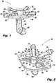
- the injector 100 includes a mounting flange 102 and a feed arm 104 extending from an inner surface 106 of the mounting flange 102.
- a spray nozzle 108 extends from an end of the feed arm 104 opposite the mounting flange 102.
- the mounting flange 102 includes at least one inlet fitting 110, in the example shown in Figs. 1-2 , there are two inlet fittings 110 but any suitable number of inlet fittings can be used.
- the inlet fittings 110 are in fluid communication with one or more respective fluid passages 112 through the feed arm 104 as indicated schematically in Fig. 1 with the broken lines.
- the spray nozzle 108 is in fluid communication with the one or more respective fluid passages 112 for issuing a spray of fluid supplied from the inlet fitting or fittings 110.
- the mounting flange 102 includes a first mounting lug 114 with a fastener bore 116 therethrough that passes through the mounting flange 102.
- a first support beam 118 extends along an outer surface 120 of the mounting flange 102 from the first mounting lug 114 to a hub 122 of the mounting flange 102.
- the first support beam 118 includes an outer surface 124 spaced apart from the outer surface 120 of the mounting flange 102 and two opposed lateral surfaces 126 each extending from the outer surface 124 of the first support beam 118 toward the outer surface 120 of the mounting flange 102.
- Inner and outer in this context are with respect to an engine case into which the injector 100 is mounted as described below.
- the outer surface 124 of the first support beam 118 includes a contour 128 with a blended radius that extends along a majority of the length from the first mounting lug 114 to the hub 122 for mitigating mechanical stresses at the first mounting lug 114.
- the contour 128 is tangent with an outer surface of the first mounting lug 114, e.g., the upper surface of the mounting lug 114 as oriented in Figs. 1-2 .
- the outer surface 124 of the first support beam 118 includes a flat portion 129 extending from the hub 122 to the contour 128.
- the contour 128 meets the flat portion 129 of the outer surface 124 of the support beam 118 at a non-tangential angle.
- contour 128 Over 75% of the outer surface 124 of the support beam 118 is included in the contour 128, and under 25% of the outer surface 124 of the support beam 118 is included in the flat portion 129.
- the radius size for contour 128 can be chosen, iteratively as needed, until the stress prediction is shown to be acceptable for a specific application.
- the support beam 118 includes a stiffening beam 130 extending, e.g., downward as oriented in Figs. 1-2 , from the lateral surfaces 126 of the support beam 118 to the outer surface 120 of the mounting flange 102.
- the stiffening beam 130 is wider than the width between the opposed lateral surfaces 126 of the support beam 118.
- the stiffening beam 130 can prevent the mounting flange 102 from over flexing, which could otherwise result in leakage at the gasket 154, which is described below.
- a second mounting lug 132 includes a fastener bore 134 therethrough that passes through the mounting flange 102.
- a second support beam 136 extends along the outer surface 102 of the mounting flange 102 from the second mounting lug 132 to the hub 122.
- the second support beam 136 is similar to the first support beam 118 and includes an outer surface 138 spaced apart from the outer surface 120 of the mounting flange 102 and two opposed lateral surfaces 140 each extending from the outer surface 138 toward the outer surface 120 of the mounting flange 102.
- the outer surface 138 of the second support beam 136 includes a contour 142 with a blended radius for mitigating mechanical stresses at the second mounting lug 132.
- the second support beam 136 also includes a stiffening beam 146 similar to that described above with respect to the first stiffening beam 130.
- the first and second lugs 114 and 132 are diametrically opposed to one another across the hub 122 of the mounting flange 102.
- the mounting flange 102 can be mounted to an engine case 148 by two fasteners 150, only one of which is shown in Fig. 3 for sake of clarity, fastened through the fastener bores 116 and 134 of the first and second mounting lugs 114 and 132.
- a gasket 154 is seated in the pocket 152, sealing between the inner surface 106 of the mounting flange 102 and the engine case 148.
- An injector shroud 156 extends through the engine case 148 around the feed arm 104, captured in the pocket 152 between the mounting flange 102 and the engine case 148.
- the top surface of the injector shroud 156 is arranged to be initially below the top surface of the gasket 154 (as oriented in Fig. 3 ) so that the gasket 154 must be compressed in order to capture the injector shroud 156 in pocket 152.
- Installing an injector 100 in an engine case 148 includes tightening the fastener 150 passing through each of the mounting lugs 114 and 132 of the mounting flange 102 to fasten the injector 100 to the engine case 148. This compresses the gasket 154 and the shroud 156 in the pocket 152 between the inner surface 106 of the mounting flange 102 and the engine case 148. Tightening the fastener 150 loads the mounting flange 102 without causing failure, e.g. at the mounting lugs 114 and 132, because the mounting flange 102 is supported by the support beams 118 and 136, which mitigate mechanical stresses at the mounting lug 114.
- Compressing the gasket 154 includes tightening two fasteners 150, e.g., by torqueing, into the two diametrically opposed mounting lugs 114 and 132, tightening the gap G between the inner surface 106 of the mounting flange 102 and the engine case 148.
- the blended radii of the contours 128 and 142 absorb stresses as the fasteners 150 are torqued, reducing the possibility of failure such as cracking at the mounting lugs 114 and 132.
- the stiffening beams 130 and 146 help prevent the flange 102 from deflecting and causing stresses when the fasteners 150 are torqued, also reducing the possibility of failure.
Landscapes
- Engineering & Computer Science (AREA)
- Chemical & Material Sciences (AREA)
- Combustion & Propulsion (AREA)
- Mechanical Engineering (AREA)
- General Engineering & Computer Science (AREA)
- Fuel-Injection Apparatus (AREA)
Abstract
Description
- The present disclosure relates to nozzles and injectors, and more particularly to mounting nozzles and injectors such as in gas turbine engines.
- Injectors and nozzles are often used to clamp components of air shrouds and seals when installing the nozzles in engine cases of gas turbine engines. Using nozzles to clamp these other components leaves a gap between the mounting flange of the nozzle and the engine case. This gap allows the mounting flange to bend and to be subjected to mechanical stress when the bolts are torqued to mount the nozzle to the engine case. This mechanical stress and bending can cause cracking, which must be corrected by replacing the nozzle.
- The conventional techniques have been considered satisfactory for their intended purpose. However, there is an ever present need for improved flange bending support. This disclosure provides a solution for this need.
- An injector includes a mounting flange and a feed arm extending from an inner surface of the mounting flange. A spray nozzle extends from an end of the feed arm opposite the mounting flange. The mounting flange includes at least one inlet fitting in fluid communication with one or more respective fluid passages through the feed arm. The spray nozzle is in fluid communication with the one or more respective fluid passages for issuing a spray of fluid supplied from the at least one inlet fitting. The mounting flange includes a first mounting lug with a fastener bore therethrough that passes through the mounting flange. A first support beam extends along an outer surface of the mounting flange from the first mounting lug to a hub of the mounting flange. The first support beam includes an outer surface spaced apart from the outer surface of the mounting flange and two opposed lateral surfaces each extending from the outer surface of the first support beam toward the outer surface of the mounting flange. The outer surface of the first support beam includes a contour with a blended radius that extends along a majority of the length from the first mounting lug to the hub for mitigating mechanical stresses at the first mounting lug.
- A second mounting lug can be included with a fastener bore therethrough that passes through the mounting flange. A second support beam can extend along the outer surface of the mounting flange from the second mounting lug to the hub of the mounting flange. The second support beam can include an outer surface spaced apart from the outer surface of the mounting flange and two opposed lateral surfaces each extending from the outer surface of the second support beam toward the outer surface of the mounting flange. The outer surface of the second support beam can include a contour with a blended radius for mitigating mechanical stresses at the second mounting lug. The first and second lugs can be diametrically opposed to one another across the hub of the mounting flange.
- An engine case can be mounted to the mounting flange by two fasteners fastened through the fastener bores of the first and second mounting lugs. There can be a pocket defined between the engine case and the inner surface of the mounting flange. A gasket can be seated in the pocket sealing between the inner surface of the mounting flange and the engine case. An injector shroud can extend through the engine case around the feed arm and can be captured in the pocket.
- The support beam can include a stiffening beam extending from the lateral surfaces of the support beam to the outer surface of the mounting flange, wherein the stiffening beam is wider than the width between the opposed lateral surfaces of the support beam. The contour of the outer surface of the first support beam can be tangent with an outer surface of the first mounting lug. The outer surface of the first support beam can include a flat portion extending from the hub to the contour. The contour can meet the flat portion of the outer surface of the support beam at a non-tangential angle. Over 75% of the outer surface of the support beam can be included in the contour, and under 25% of the outer surface of the support beam can be included in the flat portion.
- A method of installing an injector in an engine case includes tightening a fastener passing through a mounting lug of a mounting flange on an injector to fasten the injector to an engine case. There is a gasket and a shroud compressed by an inner surface of the mounting flange in a pocket of the engine case, wherein tightening the fastener loads the mounting flange without causing failure because the mounting flange is supported by a support beam extending from a hub of the mounting flange to the mounting lug. The support beam has at least one of an outer surface with a contour extending along a majority of the length from the first mounting lug to the hub for mitigating mechanical stresses at the mounting lug and/or a stiffening beam extending from opposed lateral surfaces of the support beam to an outer surface of the mounting flange wherein the stiffening beam is wider than the width between the opposed lateral surfaces. Tightening a fastener can include tightening two fasteners into two diametrically opposed mounting lugs of the mounting flange, wherein a support beam as recited in claim 11 extends from the hub to each mounting lug.
- It is also contemplated that an injector includes a mounting flange and a feed arm extending from an inner surface of the mounting flange. A spray nozzle extends from an end of the feed arm opposite the mounting flange. The mounting flange includes at least one inlet fitting in fluid communication with one or more respective fluid passages through the feed arm. The spray nozzle is in fluid communication with the one or more respective fluid passages for issuing a spray of fluid supplied from the at least one inlet fitting. The mounting flange includes a first mounting lug with fastener bore therethrough that passes through the mounting flange. A first support beam extends along an outer surface of the mounting flange from the first mounting lug to a hub of the mounting flange, wherein the first support beam includes an outer surface spaced apart from the outer surface of the mounting flange and two opposed lateral surfaces each extending from the outer surface of the first support beam toward the outer surface of the mounting flange, wherein the support beam includes a stiffening beam extending from the lateral surfaces of the support beam to the outer surface of the mounting flange, and wherein the stiffening beam is wider than the width between the opposed lateral surfaces of the support beam for preventing over flexing the mounting flange.
- A second mounting lug can be included with a fastener bore therethrough that passes through the mounting flange. A second support beam can extend along the outer surface of the mounting flange from the second mounting lug to the hub of the mounting flange. The second support beam can include an outer surface spaced apart from the outer surface of the mounting flange and two opposed lateral surfaces each extending from the outer surface of the second support beam toward the outer surface of the mounting flange, wherein the support beam includes a stiffening beam extending from the lateral surfaces of the support beam to the outer surface of the mounting flange, and wherein the stiffening beam is wider than the width between the opposed lateral surfaces of the support beam for preventing over flexing the mounting flange. The first and second lugs can be diametrically opposed to one another across the hub of the mounting flange.
- An engine case can be mounted to the mounting flange by two fasteners fastened through the fastener bores of the first and second mounting lugs, wherein there is a pocket defined between the engine case and the inner surface of the mounting flange. A gasket can be seated in the pocket sealing between the inner surface of the mounting flange and the engine case. An injector shroud can extend through the engine case around the feed arm and can be captured in the pocket.
- These and other features of the systems and methods of the subject disclosure will become more readily apparent to those skilled in the art from the following detailed description of the preferred embodiments taken in conjunction with the drawings.
- So that those skilled in the art to which the subject disclosure appertains will readily understand how to make and use the devices and methods of the subject disclosure without undue experimentation, preferred embodiments thereof will be described in detail herein below with reference to certain figures, wherein:
-
Fig. 1 is a perspective view of an exemplary embodiment of an injector constructed in accordance with the present disclosure, showing the mounting flange, feed arm, and nozzle; -
Fig. 2 is a perspective view of the injector ofFig. 1 , showing the stiffening beams and the contours of the outer surfaces of the support beams; and -
Fig. 3 is a cross-sectional side-elevation view of a portion of the injector ofFig. 1 , showing a fastener mounting the injector to an engine case. - Reference will now be made to the drawings wherein like reference numerals identify similar structural features or aspects of the subject disclosure. For purposes of explanation and illustration, and not limitation, a partial view of an exemplary embodiment of an injector in accordance with the disclosure is shown in
Fig. 1 and is designated generally byreference character 100. Other embodiments of injectors in accordance with the disclosure, or aspects thereof, are provided inFigs. 2-3 , as will be described. The systems and methods described herein can be used to mitigate and/or eliminate failures of mounting flanges during installation of injectors and nozzles such as in gas turbine engines. - The
injector 100 includes amounting flange 102 and afeed arm 104 extending from aninner surface 106 of themounting flange 102. Aspray nozzle 108 extends from an end of thefeed arm 104 opposite themounting flange 102. The mountingflange 102 includes at least one inlet fitting 110, in the example shown inFigs. 1-2 , there are twoinlet fittings 110 but any suitable number of inlet fittings can be used. Theinlet fittings 110 are in fluid communication with one or more respectivefluid passages 112 through thefeed arm 104 as indicated schematically inFig. 1 with the broken lines. Thespray nozzle 108 is in fluid communication with the one or more respectivefluid passages 112 for issuing a spray of fluid supplied from the inlet fitting orfittings 110. - With reference now to
Fig. 2 , the mountingflange 102 includes a first mountinglug 114 with afastener bore 116 therethrough that passes through the mountingflange 102. Afirst support beam 118 extends along anouter surface 120 of the mountingflange 102 from the first mountinglug 114 to ahub 122 of the mountingflange 102. Thefirst support beam 118 includes anouter surface 124 spaced apart from theouter surface 120 of the mountingflange 102 and two opposed lateral surfaces 126 each extending from theouter surface 124 of thefirst support beam 118 toward theouter surface 120 of the mountingflange 102. Inner and outer in this context are with respect to an engine case into which theinjector 100 is mounted as described below. Theouter surface 124 of thefirst support beam 118 includes acontour 128 with a blended radius that extends along a majority of the length from the first mountinglug 114 to thehub 122 for mitigating mechanical stresses at the first mountinglug 114. Thecontour 128 is tangent with an outer surface of the first mountinglug 114, e.g., the upper surface of the mountinglug 114 as oriented inFigs. 1-2 . Theouter surface 124 of thefirst support beam 118 includes aflat portion 129 extending from thehub 122 to thecontour 128. Thecontour 128 meets theflat portion 129 of theouter surface 124 of thesupport beam 118 at a non-tangential angle. Over 75% of theouter surface 124 of thesupport beam 118 is included in thecontour 128, and under 25% of theouter surface 124 of thesupport beam 118 is included in theflat portion 129. Those skilled in the art will readily appreciate that other percentages can be used for thecontour 128 andflat portion 129 without departing from the scope of this disclosure. The radius size forcontour 128 can be chosen, iteratively as needed, until the stress prediction is shown to be acceptable for a specific application. - The
support beam 118 includes astiffening beam 130 extending, e.g., downward as oriented inFigs. 1-2 , from thelateral surfaces 126 of thesupport beam 118 to theouter surface 120 of the mountingflange 102. Thestiffening beam 130 is wider than the width between the opposedlateral surfaces 126 of thesupport beam 118. Thestiffening beam 130 can prevent the mountingflange 102 from over flexing, which could otherwise result in leakage at thegasket 154, which is described below. - A second mounting
lug 132 includes afastener bore 134 therethrough that passes through the mountingflange 102. Asecond support beam 136 extends along theouter surface 102 of the mountingflange 102 from the second mountinglug 132 to thehub 122. Thesecond support beam 136 is similar to thefirst support beam 118 and includes anouter surface 138 spaced apart from theouter surface 120 of the mountingflange 102 and two opposed lateral surfaces 140 each extending from theouter surface 138 toward theouter surface 120 of the mountingflange 102. Theouter surface 138 of thesecond support beam 136 includes acontour 142 with a blended radius for mitigating mechanical stresses at the second mountinglug 132. There is aflat portion 144 on theouter surface 138 of thesecond support beam 136, and theflat portion 144 andcontour 142 are similar to those described above with respect to thefirst support beam 118. Thesecond support beam 136 also includes astiffening beam 146 similar to that described above with respect to thefirst stiffening beam 130. The first andsecond lugs hub 122 of the mountingflange 102. - With reference now to
Fig. 3 , the mountingflange 102 can be mounted to anengine case 148 by twofasteners 150, only one of which is shown inFig. 3 for sake of clarity, fastened through the fastener bores 116 and 134 of the first and second mounting lugs 114 and 132. There is apocket 152 defined between theengine case 148 and theinner surface 106 of the mountingflange 102. Agasket 154 is seated in thepocket 152, sealing between theinner surface 106 of the mountingflange 102 and theengine case 148. Aninjector shroud 156 extends through theengine case 148 around thefeed arm 104, captured in thepocket 152 between the mountingflange 102 and theengine case 148. The top surface of theinjector shroud 156 is arranged to be initially below the top surface of the gasket 154 (as oriented inFig. 3 ) so that thegasket 154 must be compressed in order to capture theinjector shroud 156 inpocket 152. - Installing an
injector 100 in anengine case 148 includes tightening thefastener 150 passing through each of the mountinglugs flange 102 to fasten theinjector 100 to theengine case 148. This compresses thegasket 154 and theshroud 156 in thepocket 152 between theinner surface 106 of the mountingflange 102 and theengine case 148. Tightening thefastener 150 loads the mountingflange 102 without causing failure, e.g. at the mountinglugs flange 102 is supported by the support beams 118 and 136, which mitigate mechanical stresses at the mountinglug 114. Compressing thegasket 154 includes tightening twofasteners 150, e.g., by torqueing, into the two diametrically opposed mountinglugs inner surface 106 of the mountingflange 102 and theengine case 148. The blended radii of thecontours fasteners 150 are torqued, reducing the possibility of failure such as cracking at the mountinglugs flange 102 from deflecting and causing stresses when thefasteners 150 are torqued, also reducing the possibility of failure. - The methods and systems of the present disclosure, as described above and shown in the drawings, provide for mounting flange bending support with superior properties including reduced mechanical stresses. While the apparatus and methods of the subject disclosure have been shown and described with reference to preferred embodiments, those skilled in the art will readily appreciate that changes and/or modifications may be made thereto without departing from the scope of the subject disclosure.
Claims (15)
- An injector comprising:a mounting flange;a feed arm extending from an inner surface of the mounting flange; anda spray nozzle extending from an end of the feed arm opposite the mounting flange, wherein the mounting flange includes at least one inlet fitting in fluid communication with one or more respective fluid passages through the feed arm, wherein the spray nozzle is in fluid communication with the one or more respective fluid passages for issuing a spray of fluid supplied from the at least one inlet fitting, and wherein the mounting flange includes:a first mounting lug with fastener bore therethrough that passes through the mounting flange; anda first support beam extending along an outer surface of the mounting flange from the first mounting lug to a hub of the mounting flange, wherein the first support beam includes an outer surface spaced apart from the outer surface of the mounting flange and two opposed lateral surfaces each extending from the outer surface of the first support beam toward the outer surface of the mounting flange, wherein the outer surface of the first support beam includes a contour with a blended radius that extends along a majority of the length from the first mounting lug to the hub for mitigating mechanical stresses at the first mounting lug.
- The injector as recited in claim 1, further comprising:a second mounting lug with a fastener bore therethrough that passes through the mounting flange; anda second support beam extending along the outer surface of the mounting flange from the second mounting lug to the hub of the mounting flange, wherein the second support beam includes an outer surface spaced apart from the outer surface of the mounting flange and two opposed lateral surfaces each extending from the outer surface of the second support beam toward the outer surface of the mounting flange, wherein the outer surface of the second support beam includes a contour with a blended radius for mitigating mechanical stresses at the second mounting lug.
- The injector as recited in claim 2, wherein the first and second lugs are diametrically opposed to one another across the hub of the mounting flange.
- The injector as recited in claim 2 or 3, further comprising:an engine case mounted to the mounting flange by two fasteners fastened through the fastener bores of the first and second mounting lugs, wherein there is a pocket defined between the engine case and the inner surface of the mounting flange;a gasket seated in the pocket sealing between the inner surface of the mounting flange and the engine case; andan injector shroud extending through the engine case around the feed arm and captured in the pocket.
- The injector as recited in any preceding claim, wherein the support beam includes a stiffening beam extending from the lateral surfaces of the support beam to the outer surface of the mounting flange, wherein the stiffening beam is wider than the width between the opposed lateral surfaces of the support beam.
- The injector as recited in any preceding claim, wherein the contour of the outer surface of the first support beam is tangent with an outer surface of the first mounting lug.
- The injector as recited in any preceding claim, wherein the outer surface of the first support beam includes a flat portion extending from the hub to the contour.
- The injector as recited in claim 6, wherein the contour meets the flat portion of the outer surface of the support beam at a non-tangential angle.
- The injector as recited in claim 6 or 7, wherein over 75% of the outer surface of the support beam is included in the contour, and under 25% of the outer surface of the support beam is included in the flat portion.
- A method of installing an injector in an engine case comprising:tightening a fastener passing through a mounting lug of a mounting flange on an injector to fasten the injector to an engine case, wherein there is a gasket and a shroud compressed by an inner surface of the mounting flange in a pocket of the engine case, wherein tightening the fastener loads the mounting flange without causing failure because the mounting flange is supported by a support beam extending from a hub of the mounting flange to the mounting lug, wherein the support beam has at least one of:an outer surface with a contour extending along a majority of the length from the first mounting lug to the hub for mitigating mechanical stresses at the mounting lug; and/ora stiffening beam extending from opposed lateral surfaces of the support beam to an outer surface of the mounting flange wherein the stiffening beam is wider than the width between the opposed lateral surfaces.
- The method as recited in claim 10, wherein tightening a fastener includes tightening two fasteners into two diametrically opposed mounting lugs of the mounting flange, wherein a respective support beam as recited in claim 10 extends from the hub to each mounting lug.
- An injector comprising:a mounting flange;a feed arm extending from an inner surface of the mounting flange; anda spray nozzle extending from an end of the feed arm opposite the mounting flange, wherein the mounting flange includes at least one inlet fitting in fluid communication with one or more respective fluid passages through the feed arm, wherein the spray nozzle is in fluid communication with the one or more respective fluid passages for issuing a spray of fluid supplied from the at least one inlet fitting, and wherein the mounting flange includes:a first mounting lug with a fastener bore therethrough that passes through the mounting flange; anda first support beam extending along an outer surface of the mounting flange from the first mounting lug to a hub of the mounting flange, wherein the first support beam includes an outer surface spaced apart from the outer surface of the mounting flange and two opposed lateral surfaces each extending from the outer surface of the first support beam toward the outer surface of the mounting flange, wherein the support beam includes a stiffening beam extending from the lateral surfaces of the support beam to the outer surface of the mounting flange, wherein the stiffening beam is wider than the width between the opposed lateral surfaces of the support beam for preventing over flexing the mounting flange.
- The injector as recited in claim 12, further comprising:a second mounting lug with a fastener bore therethrough that passes through the mounting flange; anda second support beam extending along the outer surface of the mounting flange from the second mounting lug to the hub of the mounting flange, wherein the second support beam includes an outer surface spaced apart from the outer surface of the mounting flange and two opposed lateral surfaces each extending from the outer surface of the second support beam toward the outer surface of the mounting flange, wherein the support beam includes a stiffening beam extending from the lateral surfaces of the support beam to the outer surface of the mounting flange, wherein the stiffening beam is wider than the width between the opposed lateral surfaces of the support beam for preventing over flexing the mounting flange.
- The injector as recited in claim 13, wherein the first and second lugs are diametrically opposed to one another across the hub of the mounting flange.
- The injector as recited in claim 13 or 14, further comprising:an engine case mounted to the mounting flange by two fasteners fastened through the fastener bores of the first and second mounting lugs, wherein there is a pocket defined between the engine case and the inner surface of the mounting flange;a gasket seated in the pocket sealing between the inner surface of the mounting flange and the engine case; andan injector shroud extending through the engine case around the feed arm and captured in the pocket.
Applications Claiming Priority (1)
| Application Number | Priority Date | Filing Date | Title |
|---|---|---|---|
| US15/789,610 US10480790B2 (en) | 2017-10-20 | 2017-10-20 | Flange bending support |
Publications (2)
| Publication Number | Publication Date |
|---|---|
| EP3473931A1 true EP3473931A1 (en) | 2019-04-24 |
| EP3473931B1 EP3473931B1 (en) | 2022-01-05 |
Family
ID=63965146
Family Applications (1)
| Application Number | Title | Priority Date | Filing Date |
|---|---|---|---|
| EP18201544.6A Active EP3473931B1 (en) | 2017-10-20 | 2018-10-19 | Assembly for gas turbine engine comprising an injector and an engine case |
Country Status (2)
| Country | Link |
|---|---|
| US (2) | US10480790B2 (en) |
| EP (1) | EP3473931B1 (en) |
Families Citing this family (12)
| Publication number | Priority date | Publication date | Assignee | Title |
|---|---|---|---|---|
| US11473505B2 (en) | 2020-11-04 | 2022-10-18 | Delavan Inc. | Torch igniter cooling system |
| US11608783B2 (en) | 2020-11-04 | 2023-03-21 | Delavan, Inc. | Surface igniter cooling system |
| US11692488B2 (en) | 2020-11-04 | 2023-07-04 | Delavan Inc. | Torch igniter cooling system |
| US11635027B2 (en) | 2020-11-18 | 2023-04-25 | Collins Engine Nozzles, Inc. | Fuel systems for torch ignition devices |
| US11421602B2 (en) | 2020-12-16 | 2022-08-23 | Delavan Inc. | Continuous ignition device exhaust manifold |
| US11635210B2 (en) | 2020-12-17 | 2023-04-25 | Collins Engine Nozzles, Inc. | Conformal and flexible woven heat shields for gas turbine engine components |
| US11754289B2 (en) | 2020-12-17 | 2023-09-12 | Delavan, Inc. | Axially oriented internally mounted continuous ignition device: removable nozzle |
| US11486309B2 (en) | 2020-12-17 | 2022-11-01 | Delavan Inc. | Axially oriented internally mounted continuous ignition device: removable hot surface igniter |
| US12092333B2 (en) | 2020-12-17 | 2024-09-17 | Collins Engine Nozzles, Inc. | Radially oriented internally mounted continuous ignition device |
| US11209164B1 (en) | 2020-12-18 | 2021-12-28 | Delavan Inc. | Fuel injector systems for torch igniters |
| US11680528B2 (en) | 2020-12-18 | 2023-06-20 | Delavan Inc. | Internally-mounted torch igniters with removable igniter heads |
| US12480657B1 (en) * | 2025-04-29 | 2025-11-25 | General Electric Company | Gas turbine engine and fuel nozzle therefor |
Citations (5)
| Publication number | Priority date | Publication date | Assignee | Title |
|---|---|---|---|---|
| US3398529A (en) * | 1965-09-16 | 1968-08-27 | Daimler Benz Ag | Arrangement of nozzle bodies of hooklike fuel injection nozzles at the combustion chamber of gas-turbine drive units |
| JPH0849795A (en) * | 1994-08-05 | 1996-02-20 | Kayaba Ind Co Ltd | Suction connector for pump |
| EP1887270A1 (en) * | 2006-08-10 | 2008-02-13 | United Technologies Corporation | Assembly including a seal |
| US20100071666A1 (en) * | 2008-09-19 | 2010-03-25 | Woodward Governor Company | Thermal Protection For Fuel Injectors |
| EP2375164A2 (en) * | 2010-04-07 | 2011-10-12 | Delavan Inc. | Injectors utilizing lattice support structure |
Family Cites Families (1)
| Publication number | Priority date | Publication date | Assignee | Title |
|---|---|---|---|---|
| US5988531A (en) * | 1997-11-25 | 1999-11-23 | Solar Turbines | Method of making a fuel injector |
-
2017
- 2017-10-20 US US15/789,610 patent/US10480790B2/en active Active
-
2018
- 2018-10-19 EP EP18201544.6A patent/EP3473931B1/en active Active
-
2019
- 2019-11-08 US US16/677,826 patent/US20200088409A1/en not_active Abandoned
Patent Citations (5)
| Publication number | Priority date | Publication date | Assignee | Title |
|---|---|---|---|---|
| US3398529A (en) * | 1965-09-16 | 1968-08-27 | Daimler Benz Ag | Arrangement of nozzle bodies of hooklike fuel injection nozzles at the combustion chamber of gas-turbine drive units |
| JPH0849795A (en) * | 1994-08-05 | 1996-02-20 | Kayaba Ind Co Ltd | Suction connector for pump |
| EP1887270A1 (en) * | 2006-08-10 | 2008-02-13 | United Technologies Corporation | Assembly including a seal |
| US20100071666A1 (en) * | 2008-09-19 | 2010-03-25 | Woodward Governor Company | Thermal Protection For Fuel Injectors |
| EP2375164A2 (en) * | 2010-04-07 | 2011-10-12 | Delavan Inc. | Injectors utilizing lattice support structure |
Also Published As
| Publication number | Publication date |
|---|---|
| EP3473931B1 (en) | 2022-01-05 |
| US20200088409A1 (en) | 2020-03-19 |
| US20190120490A1 (en) | 2019-04-25 |
| US10480790B2 (en) | 2019-11-19 |
Similar Documents
| Publication | Publication Date | Title |
|---|---|---|
| US10480790B2 (en) | Flange bending support | |
| US9903218B2 (en) | Turbine shroud assembly | |
| US8641101B2 (en) | Oil transfer tube and assembly | |
| US9695854B2 (en) | Adjustable and lockable turnbuckle | |
| EP2896862A1 (en) | Fastener, corresponding assembly and gas turbine | |
| EP3957842B1 (en) | Aircraft firewall feedthrough device | |
| US11293550B2 (en) | Metal-to-metal sealing system with low component spreading requirements | |
| US10731492B2 (en) | Component joint | |
| US9689573B2 (en) | Combustion equipment having a sealing member that includes a flexible sleeve | |
| EP3548707B1 (en) | Turbocharger with a sealing surface between the nozzle ring and the turbine housing | |
| GB2566884A (en) | Turbine engine assembly comprising a nose cone and a front shroud | |
| EP1956297B1 (en) | Combustion chamber of a turbomachine | |
| KR101960201B1 (en) | Terminal sealing structure for fuel rail for gasoline direct-injection engine | |
| US10746053B2 (en) | Turbocharger | |
| US10604267B2 (en) | Turbine engine including a thermal protection member | |
| US7845649B2 (en) | Methods and apparatus to facilitate sealing high pressure joints | |
| US20120161439A1 (en) | Hydraulic flange connection | |
| US9284889B2 (en) | Flexible seal system for a gas turbine engine | |
| CN121568874A (en) | Assembly comprising a blade and a system for holding the blade | |
| AU2018278763B2 (en) | A device for operation on a pressurized bolt connection between a first flanged tubular and a second flanged tubular | |
| CN107461274B (en) | Engine oil flow control by deflection | |
| US10246198B2 (en) | Alignment system for exhaust installation | |
| EP4530441A2 (en) | Thread guard | |
| WO2016076856A1 (en) | Threaded combustor housing with union nut | |
| US10633107B2 (en) | Inlet seal for a turboshaft engine |
Legal Events
| Date | Code | Title | Description |
|---|---|---|---|
| PUAI | Public reference made under article 153(3) epc to a published international application that has entered the european phase |
Free format text: ORIGINAL CODE: 0009012 |
|
| STAA | Information on the status of an ep patent application or granted ep patent |
Free format text: STATUS: THE APPLICATION HAS BEEN PUBLISHED |
|
| AK | Designated contracting states |
Kind code of ref document: A1 Designated state(s): AL AT BE BG CH CY CZ DE DK EE ES FI FR GB GR HR HU IE IS IT LI LT LU LV MC MK MT NL NO PL PT RO RS SE SI SK SM TR |
|
| AX | Request for extension of the european patent |
Extension state: BA ME |
|
| STAA | Information on the status of an ep patent application or granted ep patent |
Free format text: STATUS: REQUEST FOR EXAMINATION WAS MADE |
|
| 17P | Request for examination filed |
Effective date: 20191024 |
|
| RBV | Designated contracting states (corrected) |
Designated state(s): AL AT BE BG CH CY CZ DE DK EE ES FI FR GB GR HR HU IE IS IT LI LT LU LV MC MK MT NL NO PL PT RO RS SE SI SK SM TR |
|
| STAA | Information on the status of an ep patent application or granted ep patent |
Free format text: STATUS: EXAMINATION IS IN PROGRESS |
|
| 17Q | First examination report despatched |
Effective date: 20200807 |
|
| GRAP | Despatch of communication of intention to grant a patent |
Free format text: ORIGINAL CODE: EPIDOSNIGR1 |
|
| STAA | Information on the status of an ep patent application or granted ep patent |
Free format text: STATUS: GRANT OF PATENT IS INTENDED |
|
| INTG | Intention to grant announced |
Effective date: 20210713 |
|
| GRAS | Grant fee paid |
Free format text: ORIGINAL CODE: EPIDOSNIGR3 |
|
| GRAA | (expected) grant |
Free format text: ORIGINAL CODE: 0009210 |
|
| STAA | Information on the status of an ep patent application or granted ep patent |
Free format text: STATUS: THE PATENT HAS BEEN GRANTED |
|
| AK | Designated contracting states |
Kind code of ref document: B1 Designated state(s): AL AT BE BG CH CY CZ DE DK EE ES FI FR GB GR HR HU IE IS IT LI LT LU LV MC MK MT NL NO PL PT RO RS SE SI SK SM TR |
|
| REG | Reference to a national code |
Ref country code: GB Ref legal event code: FG4D |
|
| REG | Reference to a national code |
Ref country code: CH Ref legal event code: EP |
|
| REG | Reference to a national code |
Ref country code: AT Ref legal event code: REF Ref document number: 1460920 Country of ref document: AT Kind code of ref document: T Effective date: 20220115 |
|
| REG | Reference to a national code |
Ref country code: DE Ref legal event code: R096 Ref document number: 602018029034 Country of ref document: DE |
|
| REG | Reference to a national code |
Ref country code: IE Ref legal event code: FG4D |
|
| REG | Reference to a national code |
Ref country code: LT Ref legal event code: MG9D |
|
| RAP4 | Party data changed (patent owner data changed or rights of a patent transferred) |
Owner name: COLLINS ENGINE NOZZLES, INC. |
|
| REG | Reference to a national code |
Ref country code: NL Ref legal event code: MP Effective date: 20220105 |
|
| REG | Reference to a national code |
Ref country code: AT Ref legal event code: MK05 Ref document number: 1460920 Country of ref document: AT Kind code of ref document: T Effective date: 20220105 |
|
| PG25 | Lapsed in a contracting state [announced via postgrant information from national office to epo] |
Ref country code: NL Free format text: LAPSE BECAUSE OF FAILURE TO SUBMIT A TRANSLATION OF THE DESCRIPTION OR TO PAY THE FEE WITHIN THE PRESCRIBED TIME-LIMIT Effective date: 20220105 |
|
| PG25 | Lapsed in a contracting state [announced via postgrant information from national office to epo] |
Ref country code: SE Free format text: LAPSE BECAUSE OF FAILURE TO SUBMIT A TRANSLATION OF THE DESCRIPTION OR TO PAY THE FEE WITHIN THE PRESCRIBED TIME-LIMIT Effective date: 20220105 Ref country code: RS Free format text: LAPSE BECAUSE OF FAILURE TO SUBMIT A TRANSLATION OF THE DESCRIPTION OR TO PAY THE FEE WITHIN THE PRESCRIBED TIME-LIMIT Effective date: 20220105 Ref country code: PT Free format text: LAPSE BECAUSE OF FAILURE TO SUBMIT A TRANSLATION OF THE DESCRIPTION OR TO PAY THE FEE WITHIN THE PRESCRIBED TIME-LIMIT Effective date: 20220505 Ref country code: NO Free format text: LAPSE BECAUSE OF FAILURE TO SUBMIT A TRANSLATION OF THE DESCRIPTION OR TO PAY THE FEE WITHIN THE PRESCRIBED TIME-LIMIT Effective date: 20220405 Ref country code: LT Free format text: LAPSE BECAUSE OF FAILURE TO SUBMIT A TRANSLATION OF THE DESCRIPTION OR TO PAY THE FEE WITHIN THE PRESCRIBED TIME-LIMIT Effective date: 20220105 Ref country code: HR Free format text: LAPSE BECAUSE OF FAILURE TO SUBMIT A TRANSLATION OF THE DESCRIPTION OR TO PAY THE FEE WITHIN THE PRESCRIBED TIME-LIMIT Effective date: 20220105 Ref country code: ES Free format text: LAPSE BECAUSE OF FAILURE TO SUBMIT A TRANSLATION OF THE DESCRIPTION OR TO PAY THE FEE WITHIN THE PRESCRIBED TIME-LIMIT Effective date: 20220105 Ref country code: BG Free format text: LAPSE BECAUSE OF FAILURE TO SUBMIT A TRANSLATION OF THE DESCRIPTION OR TO PAY THE FEE WITHIN THE PRESCRIBED TIME-LIMIT Effective date: 20220405 |
|
| PG25 | Lapsed in a contracting state [announced via postgrant information from national office to epo] |
Ref country code: PL Free format text: LAPSE BECAUSE OF FAILURE TO SUBMIT A TRANSLATION OF THE DESCRIPTION OR TO PAY THE FEE WITHIN THE PRESCRIBED TIME-LIMIT Effective date: 20220105 Ref country code: LV Free format text: LAPSE BECAUSE OF FAILURE TO SUBMIT A TRANSLATION OF THE DESCRIPTION OR TO PAY THE FEE WITHIN THE PRESCRIBED TIME-LIMIT Effective date: 20220105 Ref country code: GR Free format text: LAPSE BECAUSE OF FAILURE TO SUBMIT A TRANSLATION OF THE DESCRIPTION OR TO PAY THE FEE WITHIN THE PRESCRIBED TIME-LIMIT Effective date: 20220406 Ref country code: FI Free format text: LAPSE BECAUSE OF FAILURE TO SUBMIT A TRANSLATION OF THE DESCRIPTION OR TO PAY THE FEE WITHIN THE PRESCRIBED TIME-LIMIT Effective date: 20220105 Ref country code: AT Free format text: LAPSE BECAUSE OF FAILURE TO SUBMIT A TRANSLATION OF THE DESCRIPTION OR TO PAY THE FEE WITHIN THE PRESCRIBED TIME-LIMIT Effective date: 20220105 |
|
| PG25 | Lapsed in a contracting state [announced via postgrant information from national office to epo] |
Ref country code: IS Free format text: LAPSE BECAUSE OF FAILURE TO SUBMIT A TRANSLATION OF THE DESCRIPTION OR TO PAY THE FEE WITHIN THE PRESCRIBED TIME-LIMIT Effective date: 20220505 |
|
| REG | Reference to a national code |
Ref country code: DE Ref legal event code: R097 Ref document number: 602018029034 Country of ref document: DE |
|
| PG25 | Lapsed in a contracting state [announced via postgrant information from national office to epo] |
Ref country code: SM Free format text: LAPSE BECAUSE OF FAILURE TO SUBMIT A TRANSLATION OF THE DESCRIPTION OR TO PAY THE FEE WITHIN THE PRESCRIBED TIME-LIMIT Effective date: 20220105 Ref country code: SK Free format text: LAPSE BECAUSE OF FAILURE TO SUBMIT A TRANSLATION OF THE DESCRIPTION OR TO PAY THE FEE WITHIN THE PRESCRIBED TIME-LIMIT Effective date: 20220105 Ref country code: RO Free format text: LAPSE BECAUSE OF FAILURE TO SUBMIT A TRANSLATION OF THE DESCRIPTION OR TO PAY THE FEE WITHIN THE PRESCRIBED TIME-LIMIT Effective date: 20220105 Ref country code: EE Free format text: LAPSE BECAUSE OF FAILURE TO SUBMIT A TRANSLATION OF THE DESCRIPTION OR TO PAY THE FEE WITHIN THE PRESCRIBED TIME-LIMIT Effective date: 20220105 Ref country code: DK Free format text: LAPSE BECAUSE OF FAILURE TO SUBMIT A TRANSLATION OF THE DESCRIPTION OR TO PAY THE FEE WITHIN THE PRESCRIBED TIME-LIMIT Effective date: 20220105 Ref country code: CZ Free format text: LAPSE BECAUSE OF FAILURE TO SUBMIT A TRANSLATION OF THE DESCRIPTION OR TO PAY THE FEE WITHIN THE PRESCRIBED TIME-LIMIT Effective date: 20220105 |
|
| PLBE | No opposition filed within time limit |
Free format text: ORIGINAL CODE: 0009261 |
|
| STAA | Information on the status of an ep patent application or granted ep patent |
Free format text: STATUS: NO OPPOSITION FILED WITHIN TIME LIMIT |
|
| PG25 | Lapsed in a contracting state [announced via postgrant information from national office to epo] |
Ref country code: AL Free format text: LAPSE BECAUSE OF FAILURE TO SUBMIT A TRANSLATION OF THE DESCRIPTION OR TO PAY THE FEE WITHIN THE PRESCRIBED TIME-LIMIT Effective date: 20220105 |
|
| 26N | No opposition filed |
Effective date: 20221006 |
|
| PG25 | Lapsed in a contracting state [announced via postgrant information from national office to epo] |
Ref country code: SI Free format text: LAPSE BECAUSE OF FAILURE TO SUBMIT A TRANSLATION OF THE DESCRIPTION OR TO PAY THE FEE WITHIN THE PRESCRIBED TIME-LIMIT Effective date: 20220105 |
|
| PG25 | Lapsed in a contracting state [announced via postgrant information from national office to epo] |
Ref country code: MC Free format text: LAPSE BECAUSE OF FAILURE TO SUBMIT A TRANSLATION OF THE DESCRIPTION OR TO PAY THE FEE WITHIN THE PRESCRIBED TIME-LIMIT Effective date: 20220105 |
|
| REG | Reference to a national code |
Ref country code: CH Ref legal event code: PL |
|
| REG | Reference to a national code |
Ref country code: BE Ref legal event code: MM Effective date: 20221031 |
|
| PG25 | Lapsed in a contracting state [announced via postgrant information from national office to epo] |
Ref country code: LU Free format text: LAPSE BECAUSE OF NON-PAYMENT OF DUE FEES Effective date: 20221019 |
|
| P01 | Opt-out of the competence of the unified patent court (upc) registered |
Effective date: 20230530 |
|
| PG25 | Lapsed in a contracting state [announced via postgrant information from national office to epo] |
Ref country code: LI Free format text: LAPSE BECAUSE OF NON-PAYMENT OF DUE FEES Effective date: 20221031 Ref country code: IT Free format text: LAPSE BECAUSE OF FAILURE TO SUBMIT A TRANSLATION OF THE DESCRIPTION OR TO PAY THE FEE WITHIN THE PRESCRIBED TIME-LIMIT Effective date: 20220105 Ref country code: CH Free format text: LAPSE BECAUSE OF NON-PAYMENT OF DUE FEES Effective date: 20221031 |
|
| PG25 | Lapsed in a contracting state [announced via postgrant information from national office to epo] |
Ref country code: BE Free format text: LAPSE BECAUSE OF NON-PAYMENT OF DUE FEES Effective date: 20221031 |
|
| PG25 | Lapsed in a contracting state [announced via postgrant information from national office to epo] |
Ref country code: IE Free format text: LAPSE BECAUSE OF NON-PAYMENT OF DUE FEES Effective date: 20221019 |
|
| PG25 | Lapsed in a contracting state [announced via postgrant information from national office to epo] |
Ref country code: HU Free format text: LAPSE BECAUSE OF FAILURE TO SUBMIT A TRANSLATION OF THE DESCRIPTION OR TO PAY THE FEE WITHIN THE PRESCRIBED TIME-LIMIT; INVALID AB INITIO Effective date: 20181019 |
|
| PG25 | Lapsed in a contracting state [announced via postgrant information from national office to epo] |
Ref country code: CY Free format text: LAPSE BECAUSE OF FAILURE TO SUBMIT A TRANSLATION OF THE DESCRIPTION OR TO PAY THE FEE WITHIN THE PRESCRIBED TIME-LIMIT Effective date: 20220105 |
|
| PG25 | Lapsed in a contracting state [announced via postgrant information from national office to epo] |
Ref country code: MK Free format text: LAPSE BECAUSE OF FAILURE TO SUBMIT A TRANSLATION OF THE DESCRIPTION OR TO PAY THE FEE WITHIN THE PRESCRIBED TIME-LIMIT Effective date: 20220105 |
|
| PG25 | Lapsed in a contracting state [announced via postgrant information from national office to epo] |
Ref country code: MT Free format text: LAPSE BECAUSE OF FAILURE TO SUBMIT A TRANSLATION OF THE DESCRIPTION OR TO PAY THE FEE WITHIN THE PRESCRIBED TIME-LIMIT Effective date: 20220105 |
|
| PGFP | Annual fee paid to national office [announced via postgrant information from national office to epo] |
Ref country code: GB Payment date: 20250923 Year of fee payment: 8 |
|
| PGFP | Annual fee paid to national office [announced via postgrant information from national office to epo] |
Ref country code: FR Payment date: 20250924 Year of fee payment: 8 |
|
| PG25 | Lapsed in a contracting state [announced via postgrant information from national office to epo] |
Ref country code: TR Free format text: LAPSE BECAUSE OF FAILURE TO SUBMIT A TRANSLATION OF THE DESCRIPTION OR TO PAY THE FEE WITHIN THE PRESCRIBED TIME-LIMIT Effective date: 20220105 |
|
| PGFP | Annual fee paid to national office [announced via postgrant information from national office to epo] |
Ref country code: DE Payment date: 20250923 Year of fee payment: 8 |