EP3473920A1 - Vehicular lighting fixture and lens body - Google Patents
Vehicular lighting fixture and lens body Download PDFInfo
- Publication number
- EP3473920A1 EP3473920A1 EP18201460.5A EP18201460A EP3473920A1 EP 3473920 A1 EP3473920 A1 EP 3473920A1 EP 18201460 A EP18201460 A EP 18201460A EP 3473920 A1 EP3473920 A1 EP 3473920A1
- Authority
- EP
- European Patent Office
- Prior art keywords
- light
- lens cut
- lens
- light source
- lens body
- Prior art date
- Legal status (The legal status is an assumption and is not a legal conclusion. Google has not performed a legal analysis and makes no representation as to the accuracy of the status listed.)
- Withdrawn
Links
Images





Classifications
-
- F—MECHANICAL ENGINEERING; LIGHTING; HEATING; WEAPONS; BLASTING
- F21—LIGHTING
- F21S—NON-PORTABLE LIGHTING DEVICES; SYSTEMS THEREOF; VEHICLE LIGHTING DEVICES SPECIALLY ADAPTED FOR VEHICLE EXTERIORS
- F21S43/00—Signalling devices specially adapted for vehicle exteriors, e.g. brake lamps, direction indicator lights or reversing lights
- F21S43/40—Signalling devices specially adapted for vehicle exteriors, e.g. brake lamps, direction indicator lights or reversing lights characterised by the combination of reflectors and refractors
-
- F—MECHANICAL ENGINEERING; LIGHTING; HEATING; WEAPONS; BLASTING
- F21—LIGHTING
- F21S—NON-PORTABLE LIGHTING DEVICES; SYSTEMS THEREOF; VEHICLE LIGHTING DEVICES SPECIALLY ADAPTED FOR VEHICLE EXTERIORS
- F21S43/00—Signalling devices specially adapted for vehicle exteriors, e.g. brake lamps, direction indicator lights or reversing lights
- F21S43/20—Signalling devices specially adapted for vehicle exteriors, e.g. brake lamps, direction indicator lights or reversing lights characterised by refractors, transparent cover plates, light guides or filters
- F21S43/235—Light guides
- F21S43/236—Light guides characterised by the shape of the light guide
- F21S43/239—Light guides characterised by the shape of the light guide plate-shaped
-
- F—MECHANICAL ENGINEERING; LIGHTING; HEATING; WEAPONS; BLASTING
- F21—LIGHTING
- F21S—NON-PORTABLE LIGHTING DEVICES; SYSTEMS THEREOF; VEHICLE LIGHTING DEVICES SPECIALLY ADAPTED FOR VEHICLE EXTERIORS
- F21S43/00—Signalling devices specially adapted for vehicle exteriors, e.g. brake lamps, direction indicator lights or reversing lights
- F21S43/20—Signalling devices specially adapted for vehicle exteriors, e.g. brake lamps, direction indicator lights or reversing lights characterised by refractors, transparent cover plates, light guides or filters
- F21S43/235—Light guides
- F21S43/242—Light guides characterised by the emission area
- F21S43/243—Light guides characterised by the emission area emitting light from one or more of its extremities
-
- F—MECHANICAL ENGINEERING; LIGHTING; HEATING; WEAPONS; BLASTING
- F21—LIGHTING
- F21S—NON-PORTABLE LIGHTING DEVICES; SYSTEMS THEREOF; VEHICLE LIGHTING DEVICES SPECIALLY ADAPTED FOR VEHICLE EXTERIORS
- F21S43/00—Signalling devices specially adapted for vehicle exteriors, e.g. brake lamps, direction indicator lights or reversing lights
- F21S43/20—Signalling devices specially adapted for vehicle exteriors, e.g. brake lamps, direction indicator lights or reversing lights characterised by refractors, transparent cover plates, light guides or filters
- F21S43/235—Light guides
- F21S43/247—Light guides with a single light source being coupled into the light guide
-
- F—MECHANICAL ENGINEERING; LIGHTING; HEATING; WEAPONS; BLASTING
- F21—LIGHTING
- F21S—NON-PORTABLE LIGHTING DEVICES; SYSTEMS THEREOF; VEHICLE LIGHTING DEVICES SPECIALLY ADAPTED FOR VEHICLE EXTERIORS
- F21S43/00—Signalling devices specially adapted for vehicle exteriors, e.g. brake lamps, direction indicator lights or reversing lights
- F21S43/20—Signalling devices specially adapted for vehicle exteriors, e.g. brake lamps, direction indicator lights or reversing lights characterised by refractors, transparent cover plates, light guides or filters
- F21S43/26—Refractors, transparent cover plates, light guides or filters not provided in groups F21S43/235 - F21S43/255
-
- F—MECHANICAL ENGINEERING; LIGHTING; HEATING; WEAPONS; BLASTING
- F21—LIGHTING
- F21S—NON-PORTABLE LIGHTING DEVICES; SYSTEMS THEREOF; VEHICLE LIGHTING DEVICES SPECIALLY ADAPTED FOR VEHICLE EXTERIORS
- F21S43/00—Signalling devices specially adapted for vehicle exteriors, e.g. brake lamps, direction indicator lights or reversing lights
- F21S43/30—Signalling devices specially adapted for vehicle exteriors, e.g. brake lamps, direction indicator lights or reversing lights characterised by reflectors
- F21S43/31—Optical layout thereof
- F21S43/315—Optical layout thereof using total internal reflection
-
- G—PHYSICS
- G02—OPTICS
- G02B—OPTICAL ELEMENTS, SYSTEMS OR APPARATUS
- G02B19/00—Condensers, e.g. light collectors or similar non-imaging optics
- G02B19/0033—Condensers, e.g. light collectors or similar non-imaging optics characterised by the use
- G02B19/0047—Condensers, e.g. light collectors or similar non-imaging optics characterised by the use for use with a light source
- G02B19/0061—Condensers, e.g. light collectors or similar non-imaging optics characterised by the use for use with a light source the light source comprising a LED
-
- G—PHYSICS
- G02—OPTICS
- G02B—OPTICAL ELEMENTS, SYSTEMS OR APPARATUS
- G02B19/00—Condensers, e.g. light collectors or similar non-imaging optics
- G02B19/0004—Condensers, e.g. light collectors or similar non-imaging optics characterised by the optical means employed
- G02B19/0028—Condensers, e.g. light collectors or similar non-imaging optics characterised by the optical means employed refractive and reflective surfaces, e.g. non-imaging catadioptric systems
-
- G—PHYSICS
- G02—OPTICS
- G02B—OPTICAL ELEMENTS, SYSTEMS OR APPARATUS
- G02B3/00—Simple or compound lenses
- G02B3/02—Simple or compound lenses with non-spherical faces
- G02B3/08—Simple or compound lenses with non-spherical faces with discontinuous faces, e.g. Fresnel lens
-
- G—PHYSICS
- G02—OPTICS
- G02B—OPTICAL ELEMENTS, SYSTEMS OR APPARATUS
- G02B6/00—Light guides; Structural details of arrangements comprising light guides and other optical elements, e.g. couplings
- G02B6/0001—Light guides; Structural details of arrangements comprising light guides and other optical elements, e.g. couplings specially adapted for lighting devices or systems
- G02B6/0011—Light guides; Structural details of arrangements comprising light guides and other optical elements, e.g. couplings specially adapted for lighting devices or systems the light guides being planar or of plate-like form
- G02B6/0013—Means for improving the coupling-in of light from the light source into the light guide
- G02B6/0015—Means for improving the coupling-in of light from the light source into the light guide provided on the surface of the light guide or in the bulk of it
- G02B6/0018—Redirecting means on the surface of the light guide
-
- G—PHYSICS
- G02—OPTICS
- G02B—OPTICAL ELEMENTS, SYSTEMS OR APPARATUS
- G02B6/00—Light guides; Structural details of arrangements comprising light guides and other optical elements, e.g. couplings
- G02B6/0001—Light guides; Structural details of arrangements comprising light guides and other optical elements, e.g. couplings specially adapted for lighting devices or systems
- G02B6/0011—Light guides; Structural details of arrangements comprising light guides and other optical elements, e.g. couplings specially adapted for lighting devices or systems the light guides being planar or of plate-like form
- G02B6/0033—Means for improving the coupling-out of light from the light guide
- G02B6/0035—Means for improving the coupling-out of light from the light guide provided on the surface of the light guide or in the bulk of it
- G02B6/0036—2-D arrangement of prisms, protrusions, indentations or roughened surfaces
-
- G—PHYSICS
- G02—OPTICS
- G02B—OPTICAL ELEMENTS, SYSTEMS OR APPARATUS
- G02B6/00—Light guides; Structural details of arrangements comprising light guides and other optical elements, e.g. couplings
- G02B6/0001—Light guides; Structural details of arrangements comprising light guides and other optical elements, e.g. couplings specially adapted for lighting devices or systems
- G02B6/0011—Light guides; Structural details of arrangements comprising light guides and other optical elements, e.g. couplings specially adapted for lighting devices or systems the light guides being planar or of plate-like form
- G02B6/0033—Means for improving the coupling-out of light from the light guide
- G02B6/0035—Means for improving the coupling-out of light from the light guide provided on the surface of the light guide or in the bulk of it
- G02B6/0045—Means for improving the coupling-out of light from the light guide provided on the surface of the light guide or in the bulk of it by shaping at least a portion of the light guide
Definitions
- the present invention relates to a vehicular lighting fixture and a lens body capable of causing light to exit through a part of its surface.
- a vehicular lighting fixture including a lens body having a front surface and a rear surface on the opposite side, and a light source disposed on the rear surface side of the lens body, for example, as disclosed in FIG. 1 of U.S. Patent No. 6,097,549 .
- a vehicular lighting fixture and a lens body capable of causing light to exit through a part of its surface can be provided.
- a vehicular lighting fixture can include a lens body including a front surface and a rear surface opposite to the front surface, and a light source.
- the lens body can include: a light incident portion through which light emitted from the light source enters the lens body; a lens cut portion having at least one lens cut surface configured to internally reflect light that has been emitted from the light source and has entered the lens body through the light incident portion; and a light irradiating portion that is provided on a portion of the front surface of the lens body and through which light reflected from the lens cut surface exits.
- the lens cut surface can be formed from a surface of an outer conical surface having a rotation axis so that the lens cut surface has a rotation axis which coincides with the rotation axis of the outer conical surface, and can be defined by an arbitrary surface and a vertical plane extending in a direction perpendicular to the rotation axis from a line of intersection between the arbitrary surface and an inner conical surface disposed inside the outer conical surface and having the same rotation axis as that of the outer conical surface.
- the lens cut surface can be provided to the lens cut portion between the front surface and the rear surface of the lens body and in a region overlapping with the light irradiating portion in a front view.
- This aspect can provide a vehicular lighting fixture capable of causing light to exit through a part of the front surface thereof, resulting in light emission observed substantially only in that part.
- the lens cut surface configured to internally reflect light, which has been emitted from the light source and has entered the lens body through the light incident portion, toward the light irradiating portion is provided to the lens cut portion between the front surface and the rear surface of the lens body and in a region overlapping with the light irradiating portion in a front view. That is, unlike the conventional technique described above, the lens cut surface is partially provided to the lens body.
- the light source can have an optical axis and the light incident portion can be provided on the optical axis of the light source.
- the lens body can further include a reflection surface configured to internally reflect light from the light source, which has entered through the light incident portion, radially about the optical axis of the light source.
- the lens cut surface can be provided on an optical path of reflected light from the reflection surface.
- the light irradiating portion can be provided on an optical path of reflected light from the lens cut surface.
- the lens cut surface can be formed from a surface of the outer conical surface having the rotation axis which coincides with the optical axis of the light source so that the lens cut surface has a rotation axis which coincides with the optical axis of the light source, and can be defined by the arbitrary surface and a vertical plane extending in a direction perpendicular to the optical axis of the light source from the line of intersection between the inner conical surface disposed inside the outer conical surface and the arbitrary surface.
- the vehicular lighting fixture having this configuration, light from the light source can enter through the light incident portion, can be internally reflected radially about the optical axis of the light source at the reflection surface, and can further be internally reflected by the lens cut surface toward the light irradiating portion. Accordingly, the vehicular lighting fixture can irradiate light from the light irradiating portion forward.
- the light incident portion may be provided on one end surface of the lens body which is located opposite to the lens cut portion.
- the lens cut surface may be provided on an optical path of the light that has emitted from the light source and has entered the lens body from the light incident portion.
- the light irradiating portion can be provided on an optical path of reflected light from the lens cut surface.
- the vehicular lighting fixture having this configuration, light from the light source can enter through the light incident portion and be internally reflected by the lens cut surface toward the light irradiating portion. Accordingly, the vehicular lighting fixture can irradiate light from the light irradiating portion forward.
- the vehicular lighting fixture with the aforementioned configuration can further include a reflector provided between the light source and the light incident portion, and light from the light source can enter through the light incident portion as reflected light reflected by the reflector.
- the vehicular lighting fixture having this configuration, light from the light source can enter through the light incident portion as reflected light reflected by the reflector, and be internally reflected by the lens cut surface toward the light irradiating portion. Accordingly, the vehicular lighting fixture can irradiate light from the light irradiating portion forward.
- the lens body can include a protruding portion configured to protrude in a light irradiation direction, and the light irradiating portion can be provided at a tip of the protruding portion.
- the vehicular lighting fixture having this configuration, since the reflected light from the lens cut surface can be guided to the protruding portion, more light can be irradiated from the light irradiating portion than when the protruding portion is not provided.
- the light irradiating portion can include a light irradiating region through which the reflected light from the lens cut surface can exit, and a density in the lens cut portion which indicates the number of the lens cut surfaces, each of which is contained in one segment defined between the conical surface and the vertical plane, per unit area of the lens cut portion can be adjusted to provide a region with a relatively high density and a region with a relatively low region, so that the light exiting through the light irradiating region formed can be uniformly observed.
- the light irradiating portion can irradiate light uniformly.
- a lens body can include a front surface and a rear surface opposite to the front surface.
- the lens body can include: a light incident portion through which light from a light source enters the lens body; a lens cut portion having at least one lens cut surface configured to internally reflect light that has been emitted from the light source and has entered the lens body through the light incident portion; and a light irradiating portion that is provided on a portion of the front surface of the lens body and through which light reflected from the lens cut surface exits.
- the lens cut surface can be formed from a surface of an outer conical surface having a rotation axis so that the lens cut surface has a rotation axis which coincides with the rotation axis of the outer conical surface, and can be defined by an arbitrary surface and a vertical plane extending in a direction perpendicular to the rotation axis from a line of intersection between the arbitrary surface and an inner conical surface disposed inside the outer conical surface and having the same rotation axis as that of the outer conical surface.
- the lens cut surface can be provided to the lens cut portion between the front surface and the rear surface of the lens body and in a region overlapping with the light irradiating portion in a front view.
- This aspect can provide a lens body capable of causing light to exit through a part of its surface to partially irradiate light.
- a vehicular lighting fixture can include: a lens body including a front surface and a rear surface opposite to the front surface; and a light source having an optical axis (AX).
- the lens body can include: a light incident portion through which light emitted from the light source enters the lens body; a lens cut portion configured to internally reflect light that has been emitted from the light source and has entered the lens body through the light incident portion; and a light irradiating portion that is provided on a portion of the front surface of the lens body and through which light reflected from the lens cut portion exits.
- the lens cut portion can include at least two lens cut surfaces formed from stepped separate reflection surfaces, which each include a first vertical plane (V 1 ) extending in a direction perpendicular to the optical axis (AX) of the light source; a first lens cut surface (20e 1 ) formed of a part of a second conical surface (C 2 ) having a rotation axis that coincides with the optical axis (AX) of the light source, the first lens cut surface (20e 1 ) intersecting with the first vertical plane (V 1 ) at a second intersection line (L 2 ) on an outer side extending in the direction perpendicular to the optical axis (AX) of the light source; a second vertical plane (V 2 ) positioned outside of the second intersection line (L 2 ) and on a side closer to the light irradiating portion, the second vertical plane (V 2 ) extending in the direction perpendicular to the optical axis (AX); and a second lens cut surface (20e 2 ) formed of
- the light incident portion may be provided on the optical axis of the light source
- the lens body may further include a reflection surface configured to internally reflect light from the light source, which has entered through the light incident portion, radially about the optical axis of the light source
- the lens cut portion may be provided on an optical path of reflected light from the reflection surface
- the light irradiating portion may be provided on an optical path of reflected light from the lens cut portion.
- the lens cut surfaces in the lens cut portion may have a length in the direction of the optical axis (AX) becoming shorter as the lens cut surface approaches an end portion thereof apart from the optical axis (AX).
- the aforementioned vehicular lighting fixture may further include a reflector provided between the light source and the light incident portion, wherein light from the light source enters through the light incident portion as reflected light reflected by the reflector.
- the lens cut surfaces in the lens cut portion may have a length in the direction of the optical axis (AX) becoming shorter as the lens cut surface approaches an end portion thereof apart from the optical axis (AX).
- a lens body having a front surface and a rear surface opposite to the front surface can include: a light incident portion through which light from a light source enters the lens body; a lens cut portion configured to internally reflect light that has been emitted from the light source and has entered the lens body through the light incident portion; and a light irradiating portion that is provided on a portion of the front surface of the lens body and through which light reflected from the lens cut portion exits, wherein the lens cut portion includes at least two lens cut surfaces formed from stepped separate reflection surfaces, which each include a first vertical plane (V 1 ) extending in a direction perpendicular to the optical axis (AX) of the light source; a first lens cut surface (20e 1 ) formed of a part of a second conical surface (C 2 ) having a rotation axis that coincides with the optical axis (AX) of the light source, the first lens cut surface (20e 1 ) intersecting with the first vertical plane (V
- vehicular lighting fixtures 10 (10A, 10B) of the present invention with reference to the accompanying drawings in accordance with exemplary embodiments.
- the same or corresponding component will be denoted by the same reference numeral/symbol, and a description thereof will be omitted.
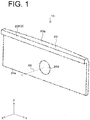
- FIG. 1 is a perspective view of a vehicular lighting fixture 10
- FIG. 2A is a front view thereof
- FIG. 2B is a rear view thereof
- FIG 2C is a cross-sectional view thereof taken along line A-A in FIG. 2A .
- the vehicular lighting fixture 10 shown in FIGS. 1 and 2A to 2C may be a tail lamp, and can be mounted on left and right sides of a rear end portion of a vehicle body (not illustrated).
- the vehicular lighting fixture 10 can include a lens body 20 having a front surface 20a and a rear surface 20b on the opposite side, and a light source 30 having an optical axis AX and disposed on the rear surface 20b side of the lens body 20.
- the vehicular lighting fixture 10 may be disposed in a lamp chamber formed by an outer lens and a housing (not illustrated), and be attached to a housing or the like.
- the XYZ axis will be defined as an orthogonal coordinate system, where the X-axis extends in the front-rear direction of a vehicle body to which the vehicular lighting fixture 10 is mounted, the Y-axis extends in the vehicle width direction, and the Z-axis extends in the vertical direction.
- the vehicular lighting fixture 10 can include an elongated light irradiating region D extending in the Y direction in front view as illustrated in FIG. 2A .
- Light reflected from a lens cut surface 20e which will be described in detail later, can exit through a light irradiating portion 20f, which also will be described in detail later, thereby forming the light irradiating region D as illustrated in FIG. 2C .
- the lens body 20 can includes a light incident portion 20c through which the light emitted from the light source 30 can enter the lens body 20, a reflection surface 20d by which the light from the light source 30 entering the lens body 20 through the light incident portion 20c can be internally reflected about the optical axis AX of the light source 30 radially (for example, by 360 degrees), a lens cut portion 20e having lens cut surfaces 20e 1 to 20e n by which the light reflected from the reflection surface 20d is internally reflected toward the light irradiating portion 20f, and the light irradiating portion 20f through which the light reflected from the lens cut surfaces 20e 1 to 20e n is irradiated.
- the lens cut surfaces 20e 1 to 20e n can be formed from a plurality of stepped separate reflection surfaces. If the lens cut surfaces 20e 1 to 20e n are not specifically distinguished, they are collectively referred to as a lens cut surface 20e (which is the same reference symbol as that for the lens cut portion).
- the light incident portion 20c can be provided substantially at the center of the rear surface 20b of the lens body 20 and on the optical axis AX of the light source 30.
- the rear surface 20b of the lens body 20 can be a plane parallel to the YZ plane, for example.
- the light incident portion 20c may include a surface that can collimate light from the light source 30 that had entered the lens body 20 through the light incident portion 20c. Specifically, the light can be converted into light beams parallel to the optical axis AX of the light source 30.
- the light source has a light emitting surface (not illustrated) and the optical axis AX that extends in a direction perpendicular to the light emitting surface thereof at substantially the center of the light emitting surface.
- the reflection surface 20d may be provided substantially at the center of the surface 20a of the lens body 20, that is, at a portion where the light incident portion 20c opposes.
- the front surface 20a of the lens body 20 may be a plane parallel to the YZ plane.
- the reflection surface 20d may be configured to internally reflect (totally reflect) light, which has been emitted from the light source 30 and has entered the lens body 20 through the light incident portion 20c, radially about the optical axis AX of the light source 30.
- the lens cut surface 20e can be configured to internally reflect the light from the reflection surface 20d toward the light irradiating portion 20f.
- the lens cut surface 20e will be described later in detail.
- the light irradiating portion 20f can be a surface through which the light reflected from the lens cut surface 20e is irradiated (projected), and provided on a part of the front surface 20a of the lens body 20. Specifically, the light irradiating portion 20f can be provided at the front end of the front surface 20a of the lens body 20 protruding from the top end of the lens body 20 (protruding leftward in FIG. 2C ), i.e., at the tip of the protruding portion 20g protruding in the light irradiation direction.
- the light irradiating portion 20f may be a planar region A1 that is parallel to the YZ plane and has a rectangular outer shape, and extends in a line shape in the Y direction as illustrated in FIG. 2A .
- the lens cut surface 20e can be provided to the lens cut portion 20e between the front surface 20a and the rear surface 20b of the lens body 20 and in a region A2 overlapping with the light irradiating portion 20f (planar region A1) in a front view.
- FIGS. 3 to 5 are diagrams for illustrating the lens cut surface 20e provided to the lens cut portion.
- the lens cut surface 20e can be produced, for example, using CAD as follows.
- a plurality of conical surfaces C 1 to C n having the optical axis AX of the light source 30 as a common rotational axis are disposed at predetermined intervals t along the optical axis AX of the light source 30.
- the optical axis AX of the light source 30 coincides with the rotational axis of each of the conical surfaces C 1 to Cn.
- n is, for example, 24, and t is, for example, 2 mm.
- Each of the conical surfaces C 1 to Cn may be formed from a conical surface having a cross-sectional apex angle of 90 degrees with respect to a plane including the optical axis AX of the light source 30.
- the cross section of each of the conical surfaces C 1 to C n in a plane perpendicular to the rotational axes may be circular, elliptical, or N-sided polygonal (when N is increased, the cross section may approach circular).
- An arbitrary plane 40 is set with respect to the optical axis AX of the light source 30.
- the arbitrary surface 40 can be formed from a curved surface of a circular arc Ar whose cross section by a plane parallel to the XY plane, for example, is concave toward the front (upward in FIG. 4 ).
- the circular arc may have a predetermined curvature.
- the arbitrary surface 40 is set in an inclined posture as illustrated in FIGS. 3 and 4 .
- the arbitrary surface 40 may be set in a posture inclined by an angle ⁇ 1 such that the reflected light RayA from the reflection surface 20d (not illustrated in FIG. 3 ) enters the arbitrary surface 40 and the arbitrary surface 40 intersects the plurality of conical surfaces C 1 to C n .
- the width of the light irradiating portion 20f can be adjusted. For example, as illustrated in FIG. 3 , by setting the inclination angle of the arbitrary surface 40 to ⁇ 1, the width of the light irradiating portion 20f can be set to W1 (see FIG. 2A ). By setting the inclination angle of the arbitrary surface 40 to ⁇ 2 which is smaller than ⁇ 1, the width of the light irradiating portion 20f can be set to W2 which is larger than W1 (see FIG. 2A ). In this manner, even if the width of the light irradiating portion 20f is set to W2 which is larger than W1 (see FIG. 2A ), it is possible to suppress the thickness Ln of the lens body 20 from becoming thicker in the direction of the optical axis AX (see FIG. 3 ).
- a vertical plane V 1 extending perpendicularly to the optical axis AX of the light source 30 is set from the intersection line L 1 between the inner first conical surface C 1 (corresponding to the inner conical surface as defined in accordance with the present invention) of a pair of mutually adjoining conical surfaces, for example, the conical surfaces C 1 and C 2 , and the arbitrary surface 40.
- part of the outer (second) conical surface C 2 (corresponding to the outer conical surface as defined in accordance with the present invention) defined by the vertical plane V 1 and the arbitrary surface 40, that is, part of the outer conical surface C 2 between the intersection line L 2 of the outer conical surface C 2 and the vertical plane V 1 and the intersection line L 3 of the outer conical surface C 2 and the arbitrary surface 40 is defined as the lens-cut surface 20e 1 .
- the lens cut surface 20e 2 can also be produced for another pair of conical surfaces adjoining each other, for example, the conical surfaces C 2 and C 3 .
- the lens cut surfaces 20e 1 to 20e n disposed along the arbitrary surface 40 can be produced.
- FIG. 6 is a cross-sectional view illustrating the vehicular lighting fixture 10 taken along line B-B in FIG. 2A .
- the length of the lens cut surface 20e in the direction of the optical axis AX becomes shorter, for example, 0.39 mm, 0.32 mm, 0.27 mm, and 0.23 mm, as it approaches the end portion (left end portion in FIG. 6 ).
- the length of the lens cut surface 20e in the direction of the optical axis AX for emitting light in the light emission range may be set to 1.19 mm, for example, as indicated in FIG. 6 .
- the length in the direction of the optical axis AX of the lens cut surface for emitting light in the same light emission range according to a conventional technique may be about 5 mm.
- the lens body 20 with the aforementioned configuration can be molded by injection molding a transparent resin such as an acrylic or polycarbonate resin using a metal mold.
- the light source 30 may be a semiconductor light emitting device such as an LED or an LD.
- the light source 30 may be mounted on a substrate (not illustrated), and fixed to a housing or the like in a state in which the light source 30 (light emitting surface thereof) and the light incident portion 20c precisely face to each other.
- the light emitted from the light source 30 can enter the lens body 20 through the light incident portion 20c. Further, the light can be internally reflected by the reflection surface 20d radially about the optical axis AX of the light source 30, and further internally reflected by the lens cut surface 20e at the lens cut portion 20e toward the light irradiating portion 20f and guided through the protruding portion 20g. As a result, the light can be irradiated through the light irradiating portion 20f forward. At this time, the light from the light source 30 can be projected through the light irradiating portion 20f as light rays parallel to the optical axis AX of the light source 30 to be irradiated forward.
- a tail lamp can be achieved.
- a lens cut may be formed in the light irradiating portion 20f to further control light irradiated through the light irradiating portion 20f by the lens cut.
- the elongated light-emitting region D extending in the Y direction can be formed by the area through which reflected light from the lens cut surface 20e is projected from the light irradiating portion 20f.
- the density of the lens cut surface 20e with respect to the lens cut portion controlled as necessary can facilitate the uniform light emission of the light emitting region D that can be visually recognized by an observer.
- the density in the lens cut portion which indicates the number of the lens cut surfaces 20e, each of which is contained in one segment defined between the conical surface and the vertical plane, per unit area of the lens cut portion can be adjusted to provide a region with a relatively high density and a region with a relatively low region, so that the light exiting through the light irradiating region formed can be uniformly observed.
- the larger the density thereof the better the uniformity of light emission observed from its front side.
- this exemplary embodiment made in accordance with the principles of the present invention can provide the vehicular lighting fixture 10 capable of causing light to be projected through a part of the front surface 20a as well as the lens body 20.
- the lens cut surface 20e of the lens cut portion 20e which can internally reflect the light, which is reflected from the reflection surface 20d, toward the light irradiating portion 20f is provided between the front surface 20a and the rear surface 20b of the lens body 20 and in the region A2 which overlaps with the light irradiating portion 20f (planar region A1) in front view. That is, unlike the conventional technique described above, this is because the lens cut surface 20e is partially provided.
- the width of the light irradiating portion 20f can be adjusted by adjusting the inclination angle of the arbitrary surface 40.
- the width of the light irradiating portion 20f can be set to the width W2 which is larger than W1 (see FIG. 2A ).
- W2 width of the light irradiating portion 20f
- the vehicular lighting fixture of the present invention is not limited thereto.
- the vehicular lighting fixture of the present invention may be applied to a stop lamp, a position lamp, a turn signal lamp, a back lamp, or a DRL (Daytime Running Lamp) lamp.
- the present invention is not limited to this.
- FIGS. 7A to 7F are each a diagram for describing a modified example of a light irradiating portion 20. These drawings show the lens cut portion where the lens cut surface 20e is formed, visually recognized through the light irradiating portion 20f.
- Modified examples of shapes or patterns of the light irradiating portion 20f or the lens cut surface 20e as seen through the light irradiating portion 20f may include an inverted L shape as illustrated in FIG. 7A , a rectangular shape as illustrated in FIG. 7B , a rhombic shape as illustrated in FIG. 7C , a square U shape as illustrated in FIG. 7D , a circular (ring) shape as illustrated in FIG. 7E , and a trapezoidal shape as illustrated in FIG. 7F , although the shape thereof is not limited these.
- the thin lens body 20 can project light regardless of the shape of the light irradiating portion 20f.
- a curved surface having a circular arc Ar e.g., a circular arc of a predetermined curvature
- a flat surface may be used, or a curved surface, a surface in which a curved surface and a flat surface are provided in combination, or the like may be used.
- the present invention is not limited thereto, and the protruding portion 20g may be omitted.
- the present invention is not limited thereto.
- FIG. 8 is a perspective view illustrating a vehicular lighting fixture 10A as a modified example
- FIG. 9A is a cross-sectional view of the vehicular lighting fixture 10A showing in FIG. 8
- FIG. 9B is a cross-sectional view of a vehicular lighting fixture 10B as a further modified example.
- the reflection surface 20d may be omitted, and the lens body 20A in which the light incident portion 20Ac is provided on one end surface of the lens body 20A may be used.
- the one end surface of the lens body is located opposite to the lens cut portion.
- the light source 30 can be disposed so as to oppose one end surface of the lens body 20A, i.e., the light incident portion 20Ac.
- the optical axis AX of the light source 30 for use in designing the lens cur surface 20e is considered as being parallel to the light irradiation portion as in the previous exemplary embodiment. The same is applied to the case shown in FIG. 9B described later.
- light from the light source 30 can enter the lens body 20A through the light incident portion 20Ac and be internally reflected by the lens cut surface 20e of the lens cut portion 20e toward the light irradiating portion 20f. Accordingly, the light can exit through the light irradiating portion 20f and be irradiated forward.
- a reflector 50 may be further provided between the light source 30 and the light incident portion 20Ac as illustrated in FIG. 9B .
- light from the light source 30 can enter the lens body 20A through the light incident portion 20Ac after reflected by the reflector 50, and be internally reflected by the lens cut surface 20e toward the light irradiating portion 20f. As a result, the light can be projected from the light irradiating portion 20f and irradiated forward.
- a semiconductor light-emitting element such as an LED, an LD, or the like is used as the light source 30
- the present invention is not limited thereto.
- a bulb light source may be used as the light source 30.
Landscapes
- Engineering & Computer Science (AREA)
- General Engineering & Computer Science (AREA)
- Physics & Mathematics (AREA)
- General Physics & Mathematics (AREA)
- Optics & Photonics (AREA)
- Non-Portable Lighting Devices Or Systems Thereof (AREA)
- Planar Illumination Modules (AREA)
Abstract
Description
- The present invention relates to a vehicular lighting fixture and a lens body capable of causing light to exit through a part of its surface.
- Conventionally, in the field of vehicular lighting fixtures, there has been known a vehicular lighting fixture including a lens body having a front surface and a rear surface on the opposite side, and a light source disposed on the rear surface side of the lens body, for example, as disclosed in
FIG. 1 ofU.S. Patent No. 6,097,549 . - In this vehicular lighting fixture of
U.S. Patent No. 6,097,549 , although the entire surface can be made to serve as a light-exiting surface, a part of the surface cannot be made to serve as a light-exiting surface, for example, in a line shape. - The present invention was devised in view of these and other problems and features in association with the conventional art. According to an aspect of the present invention, a vehicular lighting fixture and a lens body capable of causing light to exit through a part of its surface can be provided.
- According to another aspect of the present invention, a vehicular lighting fixture can include a lens body including a front surface and a rear surface opposite to the front surface, and a light source. The lens body can include: a light incident portion through which light emitted from the light source enters the lens body; a lens cut portion having at least one lens cut surface configured to internally reflect light that has been emitted from the light source and has entered the lens body through the light incident portion; and a light irradiating portion that is provided on a portion of the front surface of the lens body and through which light reflected from the lens cut surface exits. The lens cut surface can be formed from a surface of an outer conical surface having a rotation axis so that the lens cut surface has a rotation axis which coincides with the rotation axis of the outer conical surface, and can be defined by an arbitrary surface and a vertical plane extending in a direction perpendicular to the rotation axis from a line of intersection between the arbitrary surface and an inner conical surface disposed inside the outer conical surface and having the same rotation axis as that of the outer conical surface. The lens cut surface can be provided to the lens cut portion between the front surface and the rear surface of the lens body and in a region overlapping with the light irradiating portion in a front view.
- This aspect can provide a vehicular lighting fixture capable of causing light to exit through a part of the front surface thereof, resulting in light emission observed substantially only in that part.
- This can be achieved by the configuration in which the lens cut surface configured to internally reflect light, which has been emitted from the light source and has entered the lens body through the light incident portion, toward the light irradiating portion is provided to the lens cut portion between the front surface and the rear surface of the lens body and in a region overlapping with the light irradiating portion in a front view. That is, unlike the conventional technique described above, the lens cut surface is partially provided to the lens body.
- In the vehicular lighting fixture with the aforementioned configuration, the light source can have an optical axis and the light incident portion can be provided on the optical axis of the light source. The lens body can further include a reflection surface configured to internally reflect light from the light source, which has entered through the light incident portion, radially about the optical axis of the light source. The lens cut surface can be provided on an optical path of reflected light from the reflection surface. The light irradiating portion can be provided on an optical path of reflected light from the lens cut surface. The lens cut surface can be formed from a surface of the outer conical surface having the rotation axis which coincides with the optical axis of the light source so that the lens cut surface has a rotation axis which coincides with the optical axis of the light source, and can be defined by the arbitrary surface and a vertical plane extending in a direction perpendicular to the optical axis of the light source from the line of intersection between the inner conical surface disposed inside the outer conical surface and the arbitrary surface.
- With the vehicular lighting fixture having this configuration, light from the light source can enter through the light incident portion, can be internally reflected radially about the optical axis of the light source at the reflection surface, and can further be internally reflected by the lens cut surface toward the light irradiating portion. Accordingly, the vehicular lighting fixture can irradiate light from the light irradiating portion forward.
- In the vehicular lighting fixture with the aforementioned configuration, the light incident portion may be provided on one end surface of the lens body which is located opposite to the lens cut portion. The lens cut surface may be provided on an optical path of the light that has emitted from the light source and has entered the lens body from the light incident portion. The light irradiating portion can be provided on an optical path of reflected light from the lens cut surface.
- With the vehicular lighting fixture having this configuration, light from the light source can enter through the light incident portion and be internally reflected by the lens cut surface toward the light irradiating portion. Accordingly, the vehicular lighting fixture can irradiate light from the light irradiating portion forward.
- The vehicular lighting fixture with the aforementioned configuration can further include a reflector provided between the light source and the light incident portion, and light from the light source can enter through the light incident portion as reflected light reflected by the reflector.
- With the vehicular lighting fixture having this configuration, light from the light source can enter through the light incident portion as reflected light reflected by the reflector, and be internally reflected by the lens cut surface toward the light irradiating portion. Accordingly, the vehicular lighting fixture can irradiate light from the light irradiating portion forward.
- In the vehicular lighting fixture with the aforementioned configuration, the lens body can include a protruding portion configured to protrude in a light irradiation direction, and the light irradiating portion can be provided at a tip of the protruding portion.
- With the vehicular lighting fixture having this configuration, since the reflected light from the lens cut surface can be guided to the protruding portion, more light can be irradiated from the light irradiating portion than when the protruding portion is not provided.
- In the vehicular lighting fixture with the aforementioned configuration, the light irradiating portion can include a light irradiating region through which the reflected light from the lens cut surface can exit, and
a density in the lens cut portion which indicates the number of the lens cut surfaces, each of which is contained in one segment defined between the conical surface and the vertical plane, per unit area of the lens cut portion can be adjusted to provide a region with a relatively high density and a region with a relatively low region, so that the light exiting through the light irradiating region formed can be uniformly observed. - With the vehicular lighting fixture having this configuration, the light irradiating portion can irradiate light uniformly.
- According to still another aspect of the present invention, a lens body can include a front surface and a rear surface opposite to the front surface. The lens body can include: a light incident portion through which light from a light source enters the lens body; a lens cut portion having at least one lens cut surface configured to internally reflect light that has been emitted from the light source and has entered the lens body through the light incident portion; and a light irradiating portion that is provided on a portion of the front surface of the lens body and through which light reflected from the lens cut surface exits. The lens cut surface can be formed from a surface of an outer conical surface having a rotation axis so that the lens cut surface has a rotation axis which coincides with the rotation axis of the outer conical surface, and can be defined by an arbitrary surface and a vertical plane extending in a direction perpendicular to the rotation axis from a line of intersection between the arbitrary surface and an inner conical surface disposed inside the outer conical surface and having the same rotation axis as that of the outer conical surface. The lens cut surface can be provided to the lens cut portion between the front surface and the rear surface of the lens body and in a region overlapping with the light irradiating portion in a front view.
- This aspect can provide a lens body capable of causing light to exit through a part of its surface to partially irradiate light.
- This can be achieved by the configuration in which the lens cut surface configured to internally reflect light, which has been emitted from the light source and has entered the lens body through the light incident portion, toward the light irradiating portion is provided to the lens cut portion between the front surface and the rear surface of the lens body and in a region overlapping with the light irradiating portion in a front view. That is, unlike the conventional technique described above, this is because the lens cut surface is partially provided.
- According to still another aspect of the present invention, a vehicular lighting fixture can include: a lens body including a front surface and a rear surface opposite to the front surface; and a light source having an optical axis (AX). Herein, the lens body can include: a light incident portion through which light emitted from the light source enters the lens body; a lens cut portion configured to internally reflect light that has been emitted from the light source and has entered the lens body through the light incident portion; and a light irradiating portion that is provided on a portion of the front surface of the lens body and through which light reflected from the lens cut portion exits. The lens cut portion can include at least two lens cut surfaces formed from stepped separate reflection surfaces, which each include a first vertical plane (V1) extending in a direction perpendicular to the optical axis (AX) of the light source; a first lens cut surface (20e1) formed of a part of a second conical surface (C2) having a rotation axis that coincides with the optical axis (AX) of the light source, the first lens cut surface (20e1) intersecting with the first vertical plane (V1) at a second intersection line (L2) on an outer side extending in the direction perpendicular to the optical axis (AX) of the light source; a second vertical plane (V2) positioned outside of the second intersection line (L2) and on a side closer to the light irradiating portion, the second vertical plane (V2) extending in the direction perpendicular to the optical axis (AX); and a second lens cut surface (20e2) formed of a part of a third conical surface (C3) having a rotation axis that coincides with the optical axis (AX) of the light source, the second lens cut surface (20e2) intersecting with the second vertical plane (V2) at a third intersection line (L3) on an outer side extending in the direction perpendicular to the optical axis (AX) of the light source. The lens cut portion can be provided to an area between the front surface and the rear surface of the lens body and in a region overlapping with the light irradiating portion in a front view.
- In the aforementioned vehicular lighting fixture, the light incident portion may be provided on the optical axis of the light source, the lens body may further include a reflection surface configured to internally reflect light from the light source, which has entered through the light incident portion, radially about the optical axis of the light source, the lens cut portion may be provided on an optical path of reflected light from the reflection surface, and the light irradiating portion may be provided on an optical path of reflected light from the lens cut portion.
- In the aforementioned vehicular lighting fixture, the lens cut surfaces in the lens cut portion may have a length in the direction of the optical axis (AX) becoming shorter as the lens cut surface approaches an end portion thereof apart from the optical axis (AX).
- The aforementioned vehicular lighting fixture may further include a reflector provided between the light source and the light incident portion, wherein light from the light source enters through the light incident portion as reflected light reflected by the reflector. In this vehicular lighting fixture, the lens cut surfaces in the lens cut portion may have a length in the direction of the optical axis (AX) becoming shorter as the lens cut surface approaches an end portion thereof apart from the optical axis (AX).
- According to still further another aspect of the present invention, a lens body having a front surface and a rear surface opposite to the front surface, can include: a light incident portion through which light from a light source enters the lens body; a lens cut portion configured to internally reflect light that has been emitted from the light source and has entered the lens body through the light incident portion; and a light irradiating portion that is provided on a portion of the front surface of the lens body and through which light reflected from the lens cut portion exits, wherein the lens cut portion includes at least two lens cut surfaces formed from stepped separate reflection surfaces, which each include a first vertical plane (V1) extending in a direction perpendicular to the optical axis (AX) of the light source; a first lens cut surface (20e1) formed of a part of a second conical surface (C2) having a rotation axis that coincides with the optical axis (AX) of the light source, the first lens cut surface (20e1) intersecting with the first vertical plane (V1) at a second intersection line (L2) on an outer side extending in the direction perpendicular to the optical axis (AX) of the light source; a second vertical plane (V2) positioned outside of the second intersection line (L2) and on a side closer to the light irradiating portion, the second vertical plane (V2) extending in the direction perpendicular to the optical axis (AX); and a second lens cut surface (20e2) formed of a part of a third conical surface (C3) having a rotation axis that coincides with the optical axis (AX) of the light source, the second lens cut surface (20e2) intersecting with the second vertical plane (V2) at a third intersection line (L3) on an outer side extending in the direction perpendicular to the optical axis (AX) of the light source, and the lens cut portion is provided to an area between the front surface and the rear surface of the lens body and in a region overlapping with the light irradiating portion in a front view.
- These and other characteristics, features, and advantages of the present invention will become clear from the following description with reference to the accompanying drawings, wherein:
-
FIG. 1 is a perspective view of avehicular lighting fixture 10 made in accordance with principles of the present invention; -
FIG. 2A is a front view of thevehicular lighting fixture 10,FIG. 2B is a rear view of thevehicular lighting fixture 10, andFIG 2C is a cross-sectional view of thevehicular lighting fixture 10 taken along line A-A inFIG. 2A ; -
FIG. 3 is a diagram for describing alens cut surface 20e; -
FIG. 4 is another diagram for describing the lens cutsurface 20e; -
FIG. 5 is still another diagram for describing the lens cutsurface 20e; -
FIG. 6 is a cross-sectional view illustrating thevehicular lighting fixture 10 taken along line B-B inFIG. 2A ; -
FIGS. 7A to 7F are each a diagram for describing a modified example of alight irradiating portion 20f; -
FIG. 8 is a perspective view illustrating avehicular lighting fixture 10A as a modified example; and -
FIG. 9A is a cross-sectional view of thevehicular lighting fixture 10A showing inFIG. 8 , andFIG. 9B is a cross-sectional view of avehicular lighting fixture 10B as a modified example. - A description will now be made below to vehicular lighting fixtures 10 (10A, 10B) of the present invention with reference to the accompanying drawings in accordance with exemplary embodiments. In each of the drawings, the same or corresponding component will be denoted by the same reference numeral/symbol, and a description thereof will be omitted.
-
FIG. 1 is a perspective view of avehicular lighting fixture 10,FIG. 2A is a front view thereof,FIG. 2B is a rear view thereof, andFIG 2C is a cross-sectional view thereof taken along line A-A inFIG. 2A . - The
vehicular lighting fixture 10 shown inFIGS. 1 and2A to 2C may be a tail lamp, and can be mounted on left and right sides of a rear end portion of a vehicle body (not illustrated). - As illustrated in
FIGS. 2A to 2C , thevehicular lighting fixture 10 can include alens body 20 having afront surface 20a and arear surface 20b on the opposite side, and alight source 30 having an optical axis AX and disposed on therear surface 20b side of thelens body 20. Thevehicular lighting fixture 10 may be disposed in a lamp chamber formed by an outer lens and a housing (not illustrated), and be attached to a housing or the like. Hereinafter, for convenience of description, the XYZ axis will be defined as an orthogonal coordinate system, where the X-axis extends in the front-rear direction of a vehicle body to which thevehicular lighting fixture 10 is mounted, the Y-axis extends in the vehicle width direction, and the Z-axis extends in the vertical direction. - The
vehicular lighting fixture 10 can include an elongated light irradiating region D extending in the Y direction in front view as illustrated inFIG. 2A . Light reflected from a lens cutsurface 20e, which will be described in detail later, can exit through alight irradiating portion 20f, which also will be described in detail later, thereby forming the light irradiating region D as illustrated inFIG. 2C . - The
lens body 20 can includes alight incident portion 20c through which the light emitted from thelight source 30 can enter thelens body 20, areflection surface 20d by which the light from thelight source 30 entering thelens body 20 through thelight incident portion 20c can be internally reflected about the optical axis AX of thelight source 30 radially (for example, by 360 degrees), alens cut portion 20e having lens cut surfaces 20e1 to 20en by which the light reflected from thereflection surface 20d is internally reflected toward thelight irradiating portion 20f, and thelight irradiating portion 20f through which the light reflected from the lens cut surfaces 20e1 to 20en is irradiated. The lens cut surfaces 20e1 to 20en can be formed from a plurality of stepped separate reflection surfaces. If the lens cut surfaces 20e1 to 20en are not specifically distinguished, they are collectively referred to as a lens cutsurface 20e (which is the same reference symbol as that for the lens cut portion). - The
light incident portion 20c can be provided substantially at the center of therear surface 20b of thelens body 20 and on the optical axis AX of thelight source 30. Therear surface 20b of thelens body 20 can be a plane parallel to the YZ plane, for example. - The
light incident portion 20c may include a surface that can collimate light from thelight source 30 that had entered thelens body 20 through thelight incident portion 20c. Specifically, the light can be converted into light beams parallel to the optical axis AX of thelight source 30. The light source has a light emitting surface (not illustrated) and the optical axis AX that extends in a direction perpendicular to the light emitting surface thereof at substantially the center of the light emitting surface. - The
reflection surface 20d may be provided substantially at the center of thesurface 20a of thelens body 20, that is, at a portion where thelight incident portion 20c opposes. Thefront surface 20a of thelens body 20 may be a plane parallel to the YZ plane. - The
reflection surface 20d may be configured to internally reflect (totally reflect) light, which has been emitted from thelight source 30 and has entered thelens body 20 through thelight incident portion 20c, radially about the optical axis AX of thelight source 30. - The lens cut
surface 20e can be configured to internally reflect the light from thereflection surface 20d toward thelight irradiating portion 20f. The lens cutsurface 20e will be described later in detail. - The
light irradiating portion 20f can be a surface through which the light reflected from the lens cutsurface 20e is irradiated (projected), and provided on a part of thefront surface 20a of thelens body 20. Specifically, thelight irradiating portion 20f can be provided at the front end of thefront surface 20a of thelens body 20 protruding from the top end of the lens body 20 (protruding leftward inFIG. 2C ), i.e., at the tip of the protrudingportion 20g protruding in the light irradiation direction. Since the light reflected from the lens cutsurface 20e can be guided through the protrudingportion 20g, more light can be irradiated from thelight irradiating portion 20f than when the protrudingportion 20g is not provided. Thelight irradiating portion 20f may be a planar region A1 that is parallel to the YZ plane and has a rectangular outer shape, and extends in a line shape in the Y direction as illustrated inFIG. 2A . - The lens cut
surface 20e can be provided to the lens cutportion 20e between thefront surface 20a and therear surface 20b of thelens body 20 and in a region A2 overlapping with thelight irradiating portion 20f (planar region A1) in a front view. -
FIGS. 3 to 5 are diagrams for illustrating the lens cutsurface 20e provided to the lens cut portion. - The lens cut
surface 20e can be produced, for example, using CAD as follows. - First, a plurality of conical surfaces C1 to Cn having the optical axis AX of the
light source 30 as a common rotational axis are disposed at predetermined intervals t along the optical axis AX of thelight source 30. Thus, the optical axis AX of thelight source 30 coincides with the rotational axis of each of the conical surfaces C1 to Cn. Here, n is, for example, 24, and t is, for example, 2 mm. Each of the conical surfaces C1 to Cn may be formed from a conical surface having a cross-sectional apex angle of 90 degrees with respect to a plane including the optical axis AX of thelight source 30. The cross section of each of the conical surfaces C1 to Cn in a plane perpendicular to the rotational axes may be circular, elliptical, or N-sided polygonal (when N is increased, the cross section may approach circular). - An
arbitrary plane 40 is set with respect to the optical axis AX of thelight source 30. As illustrated inFIG. 4 , thearbitrary surface 40 can be formed from a curved surface of a circular arc Ar whose cross section by a plane parallel to the XY plane, for example, is concave toward the front (upward inFIG. 4 ). The circular arc may have a predetermined curvature. Thearbitrary surface 40 is set in an inclined posture as illustrated inFIGS. 3 and4 . Thearbitrary surface 40 may be set in a posture inclined by an angle θ1 such that the reflected light RayA from thereflection surface 20d (not illustrated inFIG. 3 ) enters thearbitrary surface 40 and thearbitrary surface 40 intersects the plurality of conical surfaces C1 to Cn. - When the inclination angle of the
arbitrary surface 40 is adjusted, the width of thelight irradiating portion 20f can be adjusted. For example, as illustrated inFIG. 3 , by setting the inclination angle of thearbitrary surface 40 to θ1, the width of thelight irradiating portion 20f can be set to W1 (seeFIG. 2A ). By setting the inclination angle of thearbitrary surface 40 to θ2 which is smaller than θ1, the width of thelight irradiating portion 20f can be set to W2 which is larger than W1 (seeFIG. 2A ). In this manner, even if the width of thelight irradiating portion 20f is set to W2 which is larger than W1 (seeFIG. 2A ), it is possible to suppress the thickness Ln of thelens body 20 from becoming thicker in the direction of the optical axis AX (seeFIG. 3 ). - Next, as illustrated in
FIGS. 3 and5 , a vertical plane V1 extending perpendicularly to the optical axis AX of thelight source 30 is set from the intersection line L1 between the inner first conical surface C1 (corresponding to the inner conical surface as defined in accordance with the present invention) of a pair of mutually adjoining conical surfaces, for example, the conical surfaces C1 and C2, and thearbitrary surface 40. - Next, part of the outer (second) conical surface C2 (corresponding to the outer conical surface as defined in accordance with the present invention) defined by the vertical plane V1 and the
arbitrary surface 40, that is, part of the outer conical surface C2 between the intersection line L2 of the outer conical surface C2 and the vertical plane V1 and the intersection line L3 of the outer conical surface C2 and thearbitrary surface 40 is defined as the lens-cut surface 20e1. - In the same manner, the lens cut
surface 20e2 can also be produced for another pair of conical surfaces adjoining each other, for example, the conical surfaces C2 and C3. - As described above, the lens cut surfaces 20e1 to 20en disposed along the
arbitrary surface 40 can be produced. -
FIG. 6 is a cross-sectional view illustrating thevehicular lighting fixture 10 taken along line B-B inFIG. 2A . - As illustrated in
FIG. 6 , the length of the lens cutsurface 20e in the direction of the optical axis AX becomes shorter, for example, 0.39 mm, 0.32 mm, 0.27 mm, and 0.23 mm, as it approaches the end portion (left end portion inFIG. 6 ). - The length of the lens cut
surface 20e in the direction of the optical axis AX for emitting light in the light emission range may be set to 1.19 mm, for example, as indicated inFIG. 6 . On the contrary, the length in the direction of the optical axis AX of the lens cut surface for emitting light in the same light emission range according to a conventional technique may be about 5 mm. - The
lens body 20 with the aforementioned configuration can be molded by injection molding a transparent resin such as an acrylic or polycarbonate resin using a metal mold. - The
light source 30 may be a semiconductor light emitting device such as an LED or an LD. Thelight source 30 may be mounted on a substrate (not illustrated), and fixed to a housing or the like in a state in which the light source 30 (light emitting surface thereof) and thelight incident portion 20c precisely face to each other. - In the
vehicular lighting fixture 10, when thelight source 30 is turned on, the light emitted from thelight source 30 can enter thelens body 20 through thelight incident portion 20c. Further, the light can be internally reflected by thereflection surface 20d radially about the optical axis AX of thelight source 30, and further internally reflected by the lens cutsurface 20e at the lens cutportion 20e toward thelight irradiating portion 20f and guided through the protrudingportion 20g. As a result, the light can be irradiated through thelight irradiating portion 20f forward. At this time, the light from thelight source 30 can be projected through thelight irradiating portion 20f as light rays parallel to the optical axis AX of thelight source 30 to be irradiated forward. - With the
vehicular lighting fixture 10 having this configuration, a tail lamp can be achieved. Note that a lens cut may be formed in thelight irradiating portion 20f to further control light irradiated through thelight irradiating portion 20f by the lens cut. In addition, the elongated light-emitting region D extending in the Y direction can be formed by the area through which reflected light from the lens cutsurface 20e is projected from thelight irradiating portion 20f. - Note that the density of the lens cut
surface 20e with respect to the lens cut portion controlled as necessary can facilitate the uniform light emission of the light emitting region D that can be visually recognized by an observer. Here, the density in the lens cut portion which indicates the number of thelens cut surfaces 20e, each of which is contained in one segment defined between the conical surface and the vertical plane, per unit area of the lens cut portion can be adjusted to provide a region with a relatively high density and a region with a relatively low region, so that the light exiting through the light irradiating region formed can be uniformly observed. Here, the larger the density thereof, the better the uniformity of light emission observed from its front side. - As discussed above, this exemplary embodiment made in accordance with the principles of the present invention can provide the
vehicular lighting fixture 10 capable of causing light to be projected through a part of thefront surface 20a as well as thelens body 20. - This is because the lens cut
surface 20e of the lens cutportion 20e which can internally reflect the light, which is reflected from thereflection surface 20d, toward thelight irradiating portion 20f is provided between thefront surface 20a and therear surface 20b of thelens body 20 and in the region A2 which overlaps with thelight irradiating portion 20f (planar region A1) in front view. That is, unlike the conventional technique described above, this is because the lens cutsurface 20e is partially provided. - Further according to the present exemplary embodiment, the width of the
light irradiating portion 20f can be adjusted by adjusting the inclination angle of thearbitrary surface 40. By setting the inclination angle of thearbitrary surface 40 to θ2 which is smaller than θ1, the width of thelight irradiating portion 20f can be set to the width W2 which is larger than W1 (seeFIG. 2A ). In this manner, even if the width of thelight irradiating portion 20f is set to W2 which is larger than W1, it is possible to suppress the thickness Ln of thelens body 20 from becoming thicker in the direction of the optical axis AX (seeFIG. 3 ). As a result, the costly thick-wall molding of thelens body 20, which needs to precisely control temperatures, can be avoided, whereby the production costs as well as burden during production can be reduced. - A description will now be given of modified examples.
- Although an example in which the vehicular lighting fixture of the present invention is applied to a tail lamp has been described, the present invention is not limited thereto. For example, the vehicular lighting fixture of the present invention may be applied to a stop lamp, a position lamp, a turn signal lamp, a back lamp, or a DRL (Daytime Running Lamp) lamp.
- Although an example in which the
light irradiating portion 20f extending in a line shape in the Y direction is used has been described, the present invention is not limited to this. -
FIGS. 7A to 7F are each a diagram for describing a modified example of alight irradiating portion 20. These drawings show the lens cut portion where the lens cutsurface 20e is formed, visually recognized through thelight irradiating portion 20f. - Modified examples of shapes or patterns of the
light irradiating portion 20f or the lens cutsurface 20e as seen through thelight irradiating portion 20f may include an inverted L shape as illustrated inFIG. 7A , a rectangular shape as illustrated inFIG. 7B , a rhombic shape as illustrated inFIG. 7C , a square U shape as illustrated inFIG. 7D , a circular (ring) shape as illustrated inFIG. 7E , and a trapezoidal shape as illustrated inFIG. 7F , although the shape thereof is not limited these. - According to any of these modified examples, the
thin lens body 20 can project light regardless of the shape of thelight irradiating portion 20f. - In the aforementioned exemplary embodiment, an example as the
arbitrary surface 40 has been described in which a curved surface having a circular arc Ar (e.g., a circular arc of a predetermined curvature) whose cross section obtained by cutting it with a plane parallel to the XY plane is concave toward the front (upward inFIG. 4 ) is used, but the present invention is not limited thereto. As thearbitrary surface 40, a flat surface may be used, or a curved surface, a surface in which a curved surface and a flat surface are provided in combination, or the like may be used. - Although an example in which the protruding
portion 20g that protrudes in the light irradiation direction is provided has been described, the present invention is not limited thereto, and the protrudingportion 20g may be omitted. - Although an example in which the
lens body 20 including thereflection surface 20d and thelight incident portion 20c provided on therear surface 20b is used has been described, the present invention is not limited thereto. -
FIG. 8 is a perspective view illustrating avehicular lighting fixture 10A as a modified example, andFIG. 9A is a cross-sectional view of thevehicular lighting fixture 10A showing inFIG. 8 , andFIG. 9B is a cross-sectional view of avehicular lighting fixture 10B as a further modified example. - In this exemplary embodiment as illustrated in
FIGS. 8 and9A , thereflection surface 20d may be omitted, and thelens body 20A in which the light incident portion 20Ac is provided on one end surface of thelens body 20A may be used. The one end surface of the lens body is located opposite to the lens cut portion. In this case, thelight source 30 can be disposed so as to oppose one end surface of thelens body 20A, i.e., the light incident portion 20Ac. Further, in this case, the optical axis AX of thelight source 30 for use in designing thelens cur surface 20e is considered as being parallel to the light irradiation portion as in the previous exemplary embodiment. The same is applied to the case shown inFIG. 9B described later. - In the
vehicular lighting fixture 10A with this configuration, light from thelight source 30 can enter thelens body 20A through the light incident portion 20Ac and be internally reflected by the lens cutsurface 20e of the lens cutportion 20e toward thelight irradiating portion 20f. Accordingly, the light can exit through thelight irradiating portion 20f and be irradiated forward. - As an alternative modified example, a
reflector 50 may be further provided between thelight source 30 and the light incident portion 20Ac as illustrated inFIG. 9B . - In this case, light from the
light source 30 can enter thelens body 20A through the light incident portion 20Ac after reflected by thereflector 50, and be internally reflected by the lens cutsurface 20e toward thelight irradiating portion 20f. As a result, the light can be projected from thelight irradiating portion 20f and irradiated forward. - Although an example in which a semiconductor light-emitting element such as an LED, an LD, or the like is used as the
light source 30 has been described, the present invention is not limited thereto. A bulb light source may be used as thelight source 30. - The indicated numerical values in the exemplary embodiment are illustrative, and various appropriate numerical values can be used for each size and the like.
Claims (14)
- A vehicular lighting fixture (10, 10A, 10B) comprising:a lens body (20, 20A) including a front surface (20a) and a rear surface (20b) opposite to the front surface (20a); anda light source (30), whereinthe lens body (20, 20A) comprises:a light incident portion (20c, 20Ac) through which light from the light source (30) enters the lens body (20, 20A);a lens cut portion (20e) having at least one lens cut surface (20e, 20e1 to 20en) configured to internally reflect light that has been emitted from the light source (30) and has entered the lens body (20, 20A) through the light incident portion (20c, 20Ac); anda light irradiating portion (20f) that is provided on a portion of the front surface (20a) of the lens body (20, 20A) and through which light reflected from the lens cut surface (20e, 20e1 to 20en) exits,the lens cut surface (20e, 20e1 to 20en) is formed from a surface of an outer conical surface (C2) having a rotation axis so that the lens cut surface (20e, 20e1 to 20en) has a rotation axis which coincides with the rotation axis of the outer conical surface (C2), and is defined by an arbitrary surface (40) and a vertical plane (V1) extending in a direction perpendicular to the rotation axis from a line of intersection between the arbitrary surface (40) and an inner conical surface (C1) disposed inside the outer conical surface (C2) and having the same rotation axis as that of the outer conical surface (C2), andthe lens cut surface (20e, 20e1 to 20en) is provided to the lens cut portion (20e) between the front surface (20a) and the rear surface (20b) of the lens body (20, 20A) and in a region overlapping with the light irradiating portion (20f) in a front view.
- The vehicular lighting fixture (10, 10A, 10B) according to claim 1, wherein
the light source (30) has an optical axis (AX) and the light incident portion (20c, 20Ac) is provided on the optical axis (AX) of the light source (30),
the lens body (20, 20A) further includes a reflection surface (20d) configured to internally reflect light from the light source (30), which has entered through the light incident portion (20c, 20Ac), radially about the optical axis (AX) of the light source (30),
the lens cut surface (20e, 20e1 to 20en) is provided on an optical path of reflected light from the reflection surface (20d), and
the light irradiating portion (20f) is provided on an optical path of reflected light from the lens cut surface (20e, 20e1 to 20en). - The vehicular lighting fixture (10, 10A, 10B) according to claim 1, wherein
the light incident portion (20c, 20Ac) is provided on one end surface of the lens body (20, 20A) which is located opposite to the lens cut portion (20e),
the lens cut surface (20e, 20e1 to 20en) is provided on an optical path of the light that has emitted from the light source (30) and has entered the lens body (20, 20A) from the light incident portion (20c, 20Ac), and
the light irradiating portion (20f) is provided on an optical path of reflected light from the lens cut surface (20e, 20e1 to 20en). - The vehicular lighting fixture (10B) according to claim 3, further comprising a reflector (50) provided between the light source (30) and the light incident portion (20Ac), and wherein
light from the light source (30) enters through the light incident portion (20Ac) as reflected light reflected by the reflector (50). - The vehicular lighting fixture (10, 10A, 10B) according to any one of claims 1 to 4, wherein
the lens body (20, 20A) comprises a protruding portion (20g) configured to protrude in a light irradiation direction and have a tip, and
the light irradiating portion (20f) is provided at the tip of the protruding portion (20g). - The vehicular lighting fixture (10, 10A, 10B) according to claim 1, wherein
the light irradiating portion (20f) includes a light emitting region through which the reflected light from the lens cut surface (20e, 20e1 to 20en) can exit, and
a density in the lens cut portion (20e) which indicates a number of the lens cut surfaces (20e, 20e1 to 20en), each of which is contained in one segment defined between the conical surface and the vertical plane, per unit area of the lens cut portion (20e) is adjusted to provide a region with a relatively high density and a region with a relatively low region, so that the light exiting through the light emitting region formed is uniformly observed. - A lens body (20, 20A) having a front surface (20a) and a rear surface (20b) opposite to the front surface (20a), comprising:a light incident portion (20c, 20Ac) through which light from a light source (30) enters the lens body (20, 20A);a lens cut portion (20e) having at least one lens cut surface (20e, 20e1 to 20en) configured to internally reflect light that has been emitted from the light source (30) and has entered the lens body (20, 20A) through the light incident portion (20c, 20Ac); anda light irradiating portion (20f) that is provided on a portion of the front surface (20a) of the lens body (20, 20A) and through which light reflected from the lens cut surface (20e, 20e1 to 20en) exits, whereinthe lens cut surface (20e, 20e1 to 20en) is formed from a surface of an outer conical surface (C2) having a rotation axis so that the lens cut surface (20e, 20e1 to 20en) has a rotation axis which coincides with the rotation axis of the outer conical surface (C2), and is defined by an arbitrary surface (40) and a vertical plane (V1) extending in a direction perpendicular to the rotation axis from a line of intersection between the arbitrary surface (40) and an inner conical surface (C1) disposed inside the outer conical surface (C2) and having the same rotation axis as that of the outer conical surface (C2), andthe lens cut surface (20e, 20e1 to 20en) is provided to the lens cut portion (20e) between the front surface (20a) and the rear surface (20b) of the lens body (20, 20A) and in a region overlapping with the light irradiating portion (20f) in a front view.
- A vehicular lighting fixture (10, 10A, 10B) comprising:a lens body (20, 20A) including a front surface (20a) and a rear surface (20b) opposite to the front surface (20a); anda light source (30) having an optical axis (AX), whereinthe lens body (20, 20A) comprises:a light incident portion (20c, 20Ac) through which light emitted from the light source (30) enters the lens body (20, 20A);a lens cut portion (20e) configured to internally reflect light that has been emitted from the light source (30) and has entered the lens body (20, 20A) through the light incident portion (20c, 20Ac); anda light irradiating portion (20f) that is provided on a portion of the front surface (20a) of the lens body (20, 20A) and through which light reflected from the lens cut portion (20e) exits,the lens cut portion (20e) includes at least two lens cut surfaces (20e, 20e1 to 20en) formed from stepped separate reflection surfaces (20e1 to 20en), which each include a first vertical plane (V1) extending in a direction perpendicular to the optical axis (AX) of the light source (30); a first lens cut surface (20e1) formed of a part of a second conical surface (C2) having a rotation axis that coincides with the optical axis (AX) of the light source (30), the first lens cut surface (20e1) intersecting with the first vertical plane (V1) at a second intersection line (L2) on an outer side extending in the direction perpendicular to the optical axis (AX) of the light source (30); a second vertical plane (V2) positioned outside of the second intersection line (L2) and on a side closer to the light irradiating portion (20f), the second vertical plane (V2) extending in the direction perpendicular to the optical axis (AX); and a second lens cut surface (20e2) formed of a part of a third conical surface (C3) having a rotation axis that coincides with the optical axis (AX) of the light source (30), the second lens cut surface (20e2) intersecting with the second vertical plane (V2) at a third intersection line (L3) on an outer side extending in the direction perpendicular to the optical axis (AX) of the light source (30), andthe lens cut portion (20e) is provided to an area between the front surface (20a) and the rear surface (20b) of the lens body (20, 20A) and in a region overlapping with the light irradiating portion (20f) in a front view.
- The vehicular lighting fixture (10, 10A, 10B) according to claim 8, wherein
the light incident portion (20c, 20Ac) is provided on the optical axis (AX) of the light source (30),
the lens body (20, 20A) further comprises a reflection surface (20d) configured to internally reflect light from the light source (30), which has entered through the light incident portion (20c, 20Ac), radially about the optical axis (AX) of the light source (30),
the lens cut portion (20e) is provided on an optical path of reflected light from the reflection surface (20d), and
the light irradiating portion (20f) is provided on an optical path of reflected light from the lens cut portion (20e). - The vehicular lighting fixture (10, 10A, 10B) according to claim 8, wherein the lens cut surfaces (20e, 20e1 to 20en) in the lens cut portion (20e) have a length in the direction of the optical axis (AX) becoming shorter as the lens cut surface (20e, 20e1 to 20en) approaches an end portion thereof apart from the optical axis (AX).
- The vehicular lighting fixture (10B) according to claim 8, further comprising a reflector (50) provided between the light source (30) and the light incident portion (20Ac), and wherein
light from the light source (30) enters through the light incident portion (20Ac) as reflected light reflected by the reflector (50). - The vehicular lighting fixture (10B) according to claim 11, wherein the lens cut surfaces (20e, 20e1 to 20en) in the lens cut portion (20e) have a length in the direction of the optical axis (AX) becoming shorter as the lens cut surface (20e, 20e1 to 20en) approaches an end portion thereof apart from the optical axis (AX).
- The vehicular lighting fixture (10B) according to claim 9, further comprising a reflector (50) provided between the light source (30) and the light incident portion (20Ac), and wherein
light from the light source (30) enters through the light incident portion (20Ac) as reflected light reflected by the reflector (50). - A lens body (20, 20A) having a front surface (20a) and a rear surface (20b) opposite to the front surface (20a), comprising:a light incident portion (20c, 20Ac) through which light from a light source (30) enters the lens body (20, 20A);a lens cut portion (20e) configured to internally reflect light that has been emitted from the light source (30) and has entered the lens body (20, 20A) through the light incident portion (20c, 20Ac); anda light irradiating portion (20f) that is provided on a portion of the front surface (20a) of the lens body (20, 20A) and through which light reflected from the lens cut portion (20e) exits, whereinthe lens cut portion (20e) includes at least two lens cut surfaces (20e, 20e1 to 20en) formed from stepped separate reflection surfaces (20e1 to 20en), which each include a first vertical plane (V1) extending in a direction perpendicular to the optical axis (AX) of the light source (30); a first lens cut surface (20e1) formed of a part of a second conical surface (C2) having a rotation axis that coincides with the optical axis (AX) of the light source (30), the first lens cut surface (20e1) intersecting with the first vertical plane (V1) at a second intersection line (L2) on an outer side extending in the direction perpendicular to the optical axis (AX) of the light source (30); a second vertical plane (V2) positioned outside of the second intersection line (L2) and on a side closer to the light irradiating portion (20f), the second vertical plane (V2) extending in the direction perpendicular to the optical axis (AX); and a second lens cut surface (20e2) formed of a part of a third conical surface (C3) having a rotation axis that coincides with the optical axis (AX) of the light source (30), the second lens cut surface (20e2) intersecting with the second vertical plane (V2) at a third intersection line (L3) on an outer side extending in the direction perpendicular to the optical axis (AX) of the light source (30), andthe lens cut portion (20e) is provided to an area between the front surface (20a) and the rear surface (20b) of the lens body (20, 20A) and in a region overlapping with the light irradiating portion (20f) in a front view.
Applications Claiming Priority (1)
| Application Number | Priority Date | Filing Date | Title |
|---|---|---|---|
| JP2017203527A JP2019079618A (en) | 2017-10-20 | 2017-10-20 | Vehicular lighting fixture and lens body |
Publications (1)
| Publication Number | Publication Date |
|---|---|
| EP3473920A1 true EP3473920A1 (en) | 2019-04-24 |
Family
ID=63965107
Family Applications (1)
| Application Number | Title | Priority Date | Filing Date |
|---|---|---|---|
| EP18201460.5A Withdrawn EP3473920A1 (en) | 2017-10-20 | 2018-10-19 | Vehicular lighting fixture and lens body |
Country Status (3)
| Country | Link |
|---|---|
| US (1) | US20190137068A1 (en) |
| EP (1) | EP3473920A1 (en) |
| JP (1) | JP2019079618A (en) |
Citations (11)
| Publication number | Priority date | Publication date | Assignee | Title |
|---|---|---|---|---|
| US6097549A (en) | 1997-08-12 | 2000-08-01 | Breault Research Organization, Inc. | Bireflective lens element |
| US7160010B1 (en) * | 2005-11-15 | 2007-01-09 | Visteon Global Technologies, Inc. | Light manifold for automotive light module |
| WO2007054848A1 (en) * | 2005-11-14 | 2007-05-18 | Koninklijke Philips Electronics N.V. | Thin and efficient light collimating device |
| DE102012102105A1 (en) * | 2011-03-30 | 2012-10-04 | Visteon Global Technologies, Inc. | collimator |
| JP2012243734A (en) * | 2011-05-24 | 2012-12-10 | Ichikoh Ind Ltd | Lamp fitting for vehicle |
| KR101410876B1 (en) * | 2012-12-28 | 2014-06-23 | 주식회사 에이엠에스 | Rear lamp for vehicles using total reflection |
| EP2811218A2 (en) * | 2013-06-06 | 2014-12-10 | T.Y.C. Brother Industrial Co., Ltd. | Light guide lens |
| JP2015162362A (en) * | 2014-02-27 | 2015-09-07 | 株式会社小糸製作所 | Vehicle lighting |
| WO2016009733A1 (en) * | 2014-07-14 | 2016-01-21 | 株式会社小糸製作所 | Vehicle lamp fitting |
| JP2017021963A (en) * | 2015-07-09 | 2017-01-26 | スタンレー電気株式会社 | Vehicular lighting fixture |
| JP2017092011A (en) * | 2015-11-17 | 2017-05-25 | スタンレー電気株式会社 | Light guide body and vehicular lighting tool |
Family Cites Families (2)
| Publication number | Priority date | Publication date | Assignee | Title |
|---|---|---|---|---|
| JP3187280B2 (en) * | 1995-05-23 | 2001-07-11 | シャープ株式会社 | Surface lighting device |
| DE102012221389B4 (en) * | 2012-11-22 | 2019-08-22 | Automotive Lighting Reutlingen Gmbh | Motor vehicle light with a light guide and a visible through the light guide aperture |
-
2017
- 2017-10-20 JP JP2017203527A patent/JP2019079618A/en active Pending
-
2018
- 2018-10-17 US US16/163,337 patent/US20190137068A1/en not_active Abandoned
- 2018-10-19 EP EP18201460.5A patent/EP3473920A1/en not_active Withdrawn
Patent Citations (11)
| Publication number | Priority date | Publication date | Assignee | Title |
|---|---|---|---|---|
| US6097549A (en) | 1997-08-12 | 2000-08-01 | Breault Research Organization, Inc. | Bireflective lens element |
| WO2007054848A1 (en) * | 2005-11-14 | 2007-05-18 | Koninklijke Philips Electronics N.V. | Thin and efficient light collimating device |
| US7160010B1 (en) * | 2005-11-15 | 2007-01-09 | Visteon Global Technologies, Inc. | Light manifold for automotive light module |
| DE102012102105A1 (en) * | 2011-03-30 | 2012-10-04 | Visteon Global Technologies, Inc. | collimator |
| JP2012243734A (en) * | 2011-05-24 | 2012-12-10 | Ichikoh Ind Ltd | Lamp fitting for vehicle |
| KR101410876B1 (en) * | 2012-12-28 | 2014-06-23 | 주식회사 에이엠에스 | Rear lamp for vehicles using total reflection |
| EP2811218A2 (en) * | 2013-06-06 | 2014-12-10 | T.Y.C. Brother Industrial Co., Ltd. | Light guide lens |
| JP2015162362A (en) * | 2014-02-27 | 2015-09-07 | 株式会社小糸製作所 | Vehicle lighting |
| WO2016009733A1 (en) * | 2014-07-14 | 2016-01-21 | 株式会社小糸製作所 | Vehicle lamp fitting |
| JP2017021963A (en) * | 2015-07-09 | 2017-01-26 | スタンレー電気株式会社 | Vehicular lighting fixture |
| JP2017092011A (en) * | 2015-11-17 | 2017-05-25 | スタンレー電気株式会社 | Light guide body and vehicular lighting tool |
Also Published As
| Publication number | Publication date |
|---|---|
| JP2019079618A (en) | 2019-05-23 |
| US20190137068A1 (en) | 2019-05-09 |
Similar Documents
| Publication | Publication Date | Title |
|---|---|---|
| US10060592B2 (en) | Dual beam pattern vehicular lighting assembly | |
| EP3012522B1 (en) | Vehicle lighting unit | |
| US8109664B2 (en) | Vehicle lighting equipment | |
| EP2957824B1 (en) | Vehicle lighting unit | |
| EP3388736B1 (en) | Lens body and respective headlamp for vehicle | |
| EP2657593B1 (en) | Vehicle headlamp | |
| US10288244B2 (en) | Vehicle lighting fixture | |
| EP3572847A1 (en) | Vehicular lamp | |
| JP6814070B2 (en) | Vehicle lighting | |
| JP7441104B2 (en) | Lens bodies and vehicle lights | |
| US20190137068A1 (en) | Vehicular lighting fixture and lens body | |
| EP3330595B1 (en) | Vehicular light-emitting device | |
| EP3712493B1 (en) | Vehicular lamp unit and vehicular lamp | |
| WO2020162149A1 (en) | Vehicle lighting fixture | |
| KR20200079862A (en) | lamp for vehicle | |
| JP2026073741A (en) | Vehicle lighting | |
| JP7479958B2 (en) | Vehicle lighting fixtures | |
| US10119678B2 (en) | Lighting fixture | |
| EP4567325A1 (en) | Decorative lighting assembly for a vehicle | |
| JP3985651B2 (en) | Luminous flux reflecting prism and vehicle lamp using luminous flux reflecting prism | |
| WO2023247799A1 (en) | Light guide, optical irradiation assembly, and motor vehicle | |
| EP4400366A1 (en) | Lamp for vehicle | |
| WO2023204084A1 (en) | Lens body for vehicle lamp and vehicle lamp | |
| CN107435881B (en) | Light distribution lens | |
| KR20250000770U (en) | Lamp for vehicle |
Legal Events
| Date | Code | Title | Description |
|---|---|---|---|
| PUAI | Public reference made under article 153(3) epc to a published international application that has entered the european phase |
Free format text: ORIGINAL CODE: 0009012 |
|
| AK | Designated contracting states |
Kind code of ref document: A1 Designated state(s): AL AT BE BG CH CY CZ DE DK EE ES FI FR GB GR HR HU IE IS IT LI LT LU LV MC MK MT NL NO PL PT RO RS SE SI SK SM TR |
|
| AX | Request for extension of the european patent |
Extension state: BA ME |
|
| STAA | Information on the status of an ep patent application or granted ep patent |
Free format text: STATUS: REQUEST FOR EXAMINATION WAS MADE |
|
| 17P | Request for examination filed |
Effective date: 20191023 |
|
| RBV | Designated contracting states (corrected) |
Designated state(s): AL AT BE BG CH CY CZ DE DK EE ES FI FR GB GR HR HU IE IS IT LI LT LU LV MC MK MT NL NO PL PT RO RS SE SI SK SM TR |
|
| STAA | Information on the status of an ep patent application or granted ep patent |
Free format text: STATUS: THE APPLICATION HAS BEEN WITHDRAWN |
|
| 18W | Application withdrawn |
Effective date: 20210129 |