EP3473904A1 - Valve actuator - Google Patents
Valve actuator Download PDFInfo
- Publication number
- EP3473904A1 EP3473904A1 EP17197573.3A EP17197573A EP3473904A1 EP 3473904 A1 EP3473904 A1 EP 3473904A1 EP 17197573 A EP17197573 A EP 17197573A EP 3473904 A1 EP3473904 A1 EP 3473904A1
- Authority
- EP
- European Patent Office
- Prior art keywords
- end plate
- guide channel
- valve
- valve actuator
- resilient member
- Prior art date
- Legal status (The legal status is an assumption and is not a legal conclusion. Google has not performed a legal analysis and makes no representation as to the accuracy of the status listed.)
- Granted
Links
- 239000012530 fluid Substances 0.000 claims description 15
- 230000006835 compression Effects 0.000 claims description 8
- 238000007906 compression Methods 0.000 claims description 8
- 238000005192 partition Methods 0.000 claims description 2
- 239000000463 material Substances 0.000 description 12
- 238000004519 manufacturing process Methods 0.000 description 5
- 230000001154 acute effect Effects 0.000 description 4
- 238000003466 welding Methods 0.000 description 3
- 239000004593 Epoxy Substances 0.000 description 2
- 238000005452 bending Methods 0.000 description 2
- 238000005219 brazing Methods 0.000 description 2
- 230000008878 coupling Effects 0.000 description 2
- 238000010168 coupling process Methods 0.000 description 2
- 238000005859 coupling reaction Methods 0.000 description 2
- 230000006870 function Effects 0.000 description 2
- 229910000679 solder Inorganic materials 0.000 description 2
- 238000005476 soldering Methods 0.000 description 2
- 230000007704 transition Effects 0.000 description 2
- 229910000831 Steel Inorganic materials 0.000 description 1
- 230000002378 acidificating effect Effects 0.000 description 1
- 238000004026 adhesive bonding Methods 0.000 description 1
- 230000002411 adverse Effects 0.000 description 1
- 229910045601 alloy Inorganic materials 0.000 description 1
- 239000000956 alloy Substances 0.000 description 1
- 238000004590 computer program Methods 0.000 description 1
- 238000010276 construction Methods 0.000 description 1
- 230000001419 dependent effect Effects 0.000 description 1
- 238000006073 displacement reaction Methods 0.000 description 1
- 231100001261 hazardous Toxicity 0.000 description 1
- 238000012423 maintenance Methods 0.000 description 1
- 238000000034 method Methods 0.000 description 1
- 238000012986 modification Methods 0.000 description 1
- 230000004048 modification Effects 0.000 description 1
- 230000003287 optical effect Effects 0.000 description 1
- 230000008439 repair process Effects 0.000 description 1
- 239000010959 steel Substances 0.000 description 1
- 238000003860 storage Methods 0.000 description 1
Images



Classifications
-
- F—MECHANICAL ENGINEERING; LIGHTING; HEATING; WEAPONS; BLASTING
- F16—ENGINEERING ELEMENTS AND UNITS; GENERAL MEASURES FOR PRODUCING AND MAINTAINING EFFECTIVE FUNCTIONING OF MACHINES OR INSTALLATIONS; THERMAL INSULATION IN GENERAL
- F16K—VALVES; TAPS; COCKS; ACTUATING-FLOATS; DEVICES FOR VENTING OR AERATING
- F16K31/00—Actuating devices; Operating means; Releasing devices
- F16K31/44—Mechanical actuating means
- F16K31/445—Mechanical actuating means with exterior sleeve
-
- F—MECHANICAL ENGINEERING; LIGHTING; HEATING; WEAPONS; BLASTING
- F16—ENGINEERING ELEMENTS AND UNITS; GENERAL MEASURES FOR PRODUCING AND MAINTAINING EFFECTIVE FUNCTIONING OF MACHINES OR INSTALLATIONS; THERMAL INSULATION IN GENERAL
- F16F—SPRINGS; SHOCK-ABSORBERS; MEANS FOR DAMPING VIBRATION
- F16F1/00—Springs
- F16F1/02—Springs made of steel or other material having low internal friction; Wound, torsion, leaf, cup, ring or the like springs, the material of the spring not being relevant
- F16F1/04—Wound springs
- F16F1/12—Attachments or mountings
- F16F1/128—Attachments or mountings with motion-limiting means, e.g. with a full-length guide element or ball joint connections; with protective outer cover
Definitions
- the present disclosure relates to an adjustable valve actuator. More particularly, the present disclosure focuses on an adjustable valve actuator with a helical compression spring and with a seat anchored to the spring.
- Valves generally comprise a fluid path and a flow control member situated in the fluid path.
- a stem and / or a plunger is typically anchored to the flow control member. Accordingly, the flow control member can be set in an open position and / or in a closed position by displacement of the stem and / or of the plunger.
- the valve actuator is arranged outside the enclosure surrounding the flow control member.
- the actuator is isolated or substantially isolated from potentially acidic and / or otherwise hazardous fluids flowing through the fluid path. Any adverse influences of fluids inside the enclosure on the valve actuator are thus inhibited.
- a valve actuator needs be coupled to a valve shaft.
- the valve actuator must be aligned with the stem and / or with the plunger. That is, the valve actuator has to be coupled to the stem such that at least one position of the actuator is commensurate with a position such as an open or a closed position of the flow control member.
- a first position of the actuator is commensurate with an open position of the flow control member and a second position is commensurate with a closed position.
- EP0975907A1 tension-spring return rotary actuator
- the patent application led to a granted patent EP0975907B1 .
- the grant of European patent EP0975907B1 was mentioned in the bulletin on 11 December 2002.
- EP0975907A1 teaches a cartridge 14 that houses a spring rod 52.
- a spring 54 surrounds the spring rod 52 and is mounted between end plates 54 of the cartridge 14.
- a split rod connector 57 adjustably connects spring rod 52 to lower end plate 54.
- Return cartridge 14 is nested in a spring cavity 58 of a frame 24.
- the spring 56 of EP0975907A1 pulls on a linkage 42.
- the linkage 42 then converts axial motion into rotary motion of a valve shaft 86.
- US1236826 valve-spring compressor
- US1236826 discloses an assembly with valve stems 1 and with helical springs 2 surrounding the stems 1.
- a spring seat 3 is mounted to an end portion of each of the springs 2.
- An operating lever 11 cooperates with a lifting plate 7 to allow compression of the springs 2.
- the pivotally connected operating lever 11 is employed to shift the lifting plate 7 along an axis defined by the valve stems 1.
- the present disclosure improves on valves with external valve actuators.
- the instant disclosure aims at providing a unitary valve actuator with relatively few parts.
- the present disclosure provides a valve actuator nested in a spring return cartridge.
- the spring return cartridge encloses a resilient member such as a (helical and / or compression) spring.
- the spring return cartridge also provides a guide channel with two opposite ends. A first end plate is situated at the first end of the guide channel. A second end plate is situated at the second end of the guide channel. The second end plate sits opposite the first end plate.
- An arcuate arm joins the second end plate and the guide channel such that the second end plate is aligned in parallel or substantially in parallel to the first end plate.
- the guide channel, the arcuate arm and the end plate form a single piece.
- the valve actuator described above is adapted for low cost manufacture at large scale.
- the resilient member is compressed in order that the resilient member becomes shorter than the guide channel.
- the resilient member then fits inside the guide channel.
- An auxiliary plate may be placed atop the resilient member to facilitate compression. Once the resilient member is sufficiently compressed, the arm is bent and the second end plate is brought in alignment with the first end plate. Finally, an auxiliary plate interposed between the resilient member and the second end plate may be removed.
- the flange may, in particular, be welded to a frame of a valve.
- a threaded portion protrudes from the second end plate. The latter portion may engage a portion of a frame commensurate with the threaded portion, thereby locking the cartridge to the frame.
- the spring seat advantageously allows for adjustable (but permanent) anchorage and / or coupling to a rod extending from the aperture of the second end plate.
- the unitary valve actuator of the instant disclosure is typically part of a valve.
- the valve provides an enclosure with at least one inlet and with at least one outlet.
- a fluid path connects the at least one inlet to the at least one outlet.
- a valve according to the instant disclosure also provides a flow control element situated in the fluid path. In a first position, the flow control element enables fluid flow through the fluid path. In a second position, the flow control element obturates fluid flow.
- the flow control element is a throttle.
- a stem and / or a plunger typically couples the valve element to an actuator.
- the stem and / or the plunger transmits torque and / or momentum / force from the valve actuator to the valve element, thereby enabling automated adjustments of valve positions.
- the valve actuator of the instant disclosure is typically flanged on a frame and / or on an enclosure of a valve. That is, the valve actuator sits outside the fluid path.
- the valve actuator is a unitary valve actuator.
- FIG 1 depicts a valve actuator 1 according to the instant disclosure during assembly.
- Valve actuator 1 comprises a cartridge 2 such as a spring cartridge.
- Cartridge 2 has a guide channel 3, preferably a cylindrical guide channel. It is also envisaged that the cross-section of the guide channel 3 is quadratic, triangular, rectangular and / or polygonal.
- the guide channel 3 is a tubular portion and / or a barrel and / or a (longitudinal) channel. In another embodiment, the guide channel 3 is a (longitudinal) chassis. In yet another embodiment, the guide channel 3 is an assembly with a plurality of parallel guide runners such as two, three, five, or even ten guide runners. These guide runners are ideally disposed (symmetrically) around a resilient member 5.
- Guide channel 3 provides a first end and a second end.
- a first end plate 4 is arranged at the first end of guide channel.
- end plate 4 is an end disc.
- the cross-section of end plate 4 matches the cross-section of guide channel 3 or is commensurate with the cross-section of guide channel 3.
- first end plate 4 is welded onto guide channel 3 and / or glued onto guide channel 3 and / or bolted to guide channel 3 and / or inserted. It is envisaged that the first end plate 4 is an integral part of the guide channel 3. That is, the first end plate 4 and the guide channel 3 form a single piece and / or are made of the same material(s) and / or are made out of a single piece of material.
- a resilient member 5 is situated inside guide channel 3.
- Guide channel 3 thus encloses resilient member 5 such that resilient member 5 cannot escape.
- Guide channel 3 may, by way of non-limiting example, comprise slots and / or orifices to the extent that resilient member 5 remains inside guide channel 3.
- resilient member 5 is a spring.
- Resilient member 5 can, in particular, comprise a helical spring and / or a compression spring and / or a helical compression spring.
- resilient member 5 comprises at least a disc spring.
- the at least a disc spring preferably provides at least an aperture for stem 11. Disc springs confer benefits in terms of providing large torque and / or momentum and / or forces to any appliance coupled to actuator 1 and / or stem 11.
- Resilient member 5 is joined to and / or anchored to a seat 6 such as a spring seat.
- FIG 1 shows the seat 6 arranged adjacent the first end plate 4.
- Seat 6 generally is slidable along guide channel 3 whilst first end plate 4 is generally not slidable.
- Seat 6 advantageously joins resilient member 5 at a far end of resilient member 5.
- Seat 6 can, by way of example, be fitted to seat 6 by means of a welded and / or a glued joint and / or by means of a threaded and / or snap-on connection.
- Seat 6 ideally has a shape with a cross-section that matches the cross-section of guide channel 3 and / or is commensurate with the cross-section of guide channel 3.
- FIG 1 also shows an auxiliary tool 7 arranged at the other far end of resilient member 5.
- Auxiliary tool 7 is typically inserted during assembly when the resilient member 5 is compressed.
- Auxiliary tool 7 as such is not connected to and / or joined to and / or affixed to resilient member 5. Consequently, auxiliary tool 7 may be removed sideways (from cartridge 2) upon completion of assembly of valve actuator 1.
- the skilled person arranges suitable slots and / or orifices along guide channel 3 such that auxiliary tool 7 can be removed.
- Arcuate arms 8a, 8b are arranged at the second end of guide channel 3.
- FIG 1 shows an arrangement with two arcuate arms 8a, 8b extending from the guide channel 3.
- one arcuate arm is provided.
- Arcuate arms 8a, 8b each extend along a portion of the perimeter of the opening at the second end of guide channel 3. According to an aspect, this portion is approximately 80% of the perimeter and / or approximately 50% of the perimeter and / or approximately 20% of the perimeter.
- the arcuate arms 8a, 8b are integral with the guide channel 3. That is, the arcuate arms 8a, 8b and the guide channel 3 form a single piece.
- the wall thickness of the arcuate arms 8a, 8b is ideally lower than the wall thickness of guide channel 3 in order that the arcuate arms 8a, 8b can be bent.
- the thickness of the arcuate arms 8a, 8b is approximately 70% of the wall thickness of guide channel 3 or approximately 50% of the wall thickness of guide channel 3 or approximately 30% of the wall thickness of guide channel 3.
- suitable materials for the arcuate arms 8a, 8b With suitably chosen materials these arms 8a, 8b can be bent and / or be deformed and (substantially) remain in their final positions.
- FIG 1 shows an arrangement with two end plates 9a, 9b extending from the arms 8a, 8b.
- second end plates 9a, 9b are end discs.
- the cross-sections of second end plates 9a, 9b can be combined to match the cross-section of guide channel 3.
- the cross-sections of second end plates 9a, 9b can be combined to be commensurate with the cross-section of guide channel 3.
- the combined cross-sections of end plates 9a, 9b (or of a single second end plate) match and / or are the commensurate with the cross-section of first end plate 4.
- the second end plates 9a, 9b are integral with the arms 8a, 8b. That is, the second end plates 9a, 9b and the arms 8a, 8b and / or the guide channel 3 form a single piece and / or are made of the same material(s).
- the arms 8a, 8b (or the arm) thus join and / or anchor the second and plates 9a, 9b (or the single second end plate) to guide channel 3.
- suitable materials such as (alloy) steel and / or polymeric materials for these parts.
- the arms 8a, 8b may be bent and / or flexed as indicated by arrows 10a, 10b. In so doing, the second end plates 9a, 9b (or the single second end plate) move and / or are deflected toward their final positions. After bending and / or flexure, the end plates 9a, 9b will remain or substantially remain in their final positions.
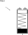
- FIG 2 shows the second end plates 9a, 9b in their final positions.
- the second end plates 9a, 9b (or the single second end plate) are then aligned in parallel or substantially in parallel to the first end plate 4. It is also envisaged that in their final positions, the second end plates 9a, 9b (or the single second end plate) are orientated perpendicular or substantially perpendicular to the walls of guide channel 3.
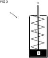
- FIG 3 depicts a valve actuator 1 with axially displaceable mobile parts 5, 6, 11.
- valve actuator 1 both to axially displaceable flow control elements and to pivotal flow control elements.
- valve actuator 1 of the instant disclosure both to axially displaceable flow control elements and to pivotal flow control elements (butterfly valves).
- the second end plates 9a, 9b (or the single second end plate) were sufficiently extended, they would form acute angles with the first end plate 4. In an embodiment, these acute angles are less than 10 degrees, in particular less than 5 degrees or even less than 2 degrees.
- the second end plates 9a, 9b in their final positions are arranged such that resilient member 5 can no longer leave or escape from the cartridge 2. That is, resilient member 5 will remain inside the cartridge 2 even after removal of auxiliary tool 7.
- the second end plates 9a, 9b (or the single second end plate) loosely support resilient member 5 and / or are not joined to and / or not affixed to resilient member 5.
- valve actuator 1 is depicted with a valve stem 11 anchored to seat 6.
- the stem and / or plunger and / or rod 11 functions to transmit momentum from resilient member 5 via seat 6 to a flow control member.
- stem and / or plunger and / or rod 11 is to be (mechanically) coupled to a flow control member of a valve.
- the second end plates 9a, 9b (or the single second end plate) provide a suitable aperture such that stem and / or plunger and / or rod 11 can extend from seat 6 inside cartridge 2 to a flow control member situated outside cartridge 2.
- the aperture preferably has a circular cross-section.
- the cross-section of the aperture for the stem and / or the plunger and / or the rod 11 is triangular, quadratic, rectangular and / or polygonal.
- the aperture of the second end plates 9a, 9b (or of the single second end plate) has a depth dimension that is parallel to stem and / or plunger and / or rod 11.
- the aperture of the second end plates 9a, 9b also has a diameter dimension that is perpendicular to stem and / or plunger and / or rod 11. It is envisaged that the diameter dimension of the aperture exceeds its depth dimension at least by a factor 2 and / or at least by a factor 5 and / or at least by a factor 10.
- actuator 1 can be attached to a frame and / or to a housing of valve.
- the second end plates 9a, 9b (or the single second end plate) provide a flange pointing away from seat 6 and / or away from resilient member 5.
- the flange of the second end plates 9a, 9b (or of the single second end plate) generally is opposite the surface that (loosely) supports resilient member 5.
- Valve actuator 1 is advantageously affixed to the frame or to the housing by welding (at least one of) the flange to the frame or to the housing.
- the flange of the end plates 9a, 9b can be soldered, in particular soldered using brazing solder, to a frame and / or to an enclosure of a valve.
- the flange of the end plates 9a, 9b (or of the single second end plate) can be (epoxy) glued to a frame and / or to an enclosure of valve.
- the flange of the second end plates 9a, 9b (or of the single second end plate) provides a threaded portion (protruding from the surface).
- the protrusion with the threaded portion enables locking engagement of valve actuator 1 to a frame and / or to an enclosure of a valve.
- the frame and / or the enclosure also provides a threaded portion that is compatible with the threaded portion of the protrusion. That is, the threaded portion of the protrusion allows a bolted joint between the cartridge 2 and a frame and / or an enclosure of a valve.
- FIG 4 a valve actuator 1 with a single second end plate 9 is shown.
- the single second end plate 9 is anchored to the guide channel 3 via a single arcuate arm 8.
- the single (deformable) arm 8 is bent toward its final position as shown on FIG 4 .
- the single second end plate 9 moves and / or is deflected toward its final positions. After bending and / or flexure, the end plate 9 will remain or substantially remain in its final position.
- this acute angle is less than 10 degrees, in particular less than 5 degrees or even less than 2 degrees.
- the second end plate 9 provides a suitable aperture such that stem and / or plunger and / or rod 11 can extend from seat 6 inside cartridge 2 to a flow control member situated outside cartridge 2.
- the aperture preferably has a circular cross-section.
- the cross-section of the aperture for stem 11 is triangular, quadratic, rectangular and / or polygonal.
- the aperture of the second end plate 9 has a depth dimension that is parallel to stem and / or plunger and / or rod 11.
- the aperture of the second end plate 9 also has a diameter dimension that is perpendicular to stem and / or plunger and / or rod 11. It is envisaged that the diameter dimension of the aperture exceeds its depth dimension at least by a factor 2 and / or at least by a factor 5 and / or at least by a factor 10.
- actuator 1 can be attached to a frame and / or to a housing of valve.
- the single second end plate 9 provides a flange pointing away from seat 6 and / or away from resilient member 5.
- the flange of the single second end plate 9 generally is opposite the surface that (loosely) supports resilient member 5.
- Valve actuator 1 is advantageously affixed to the frame or to the housing by welding the flange to the frame and / or to the housing.
- the flange of the single second end plate 9 can be soldered, in particular soldered using brazing solder, to a frame and / or to an enclosure of valve.
- the flange of the single second end plate 9 can be (epoxy) glued to a frame and / or to an enclosure of valve.
- a suitable access aperture allows adjustments of the positions of the seat 6 and / or of the resilient member 5.
- the position of the seat 6 may, for instance, be adjusted when the seat 6 is joined with the stem 11.
- An access aperture may also be required for maintenance and / or repair of the assembly.
- the end plate 4 of FIG 5 provides such an access aperture 12.
- a tool such as a pin or a screwdriver can be inserted into access aperture 12 in order to shift seat 6 along guide channel 3.
- the skilled person chooses suitable dimensions for an opening such as access aperture 12.
- the access aperture 12 preferably has a circular cross-section.
- the cross-section of the access aperture 12 is triangular, quadratic, rectangular and / or polygonal.
- the aperture of the access aperture 12 has a depth dimension that is parallel to stem and / or plunger and / or rod 11.
- the access aperture 12 also has a diameter dimension that is perpendicular to stem and / or plunger and / or rod 11. It is envisaged that the diameter dimension of the opening 12 exceeds its depth dimension at least by a factor 2 and / or at least by a factor 5 and / or at least by a factor 10.
- the skilled person also envisages access apertures situated in any (lateral) walls of guide channel 3.
- the skilled person does, in particular, envisage suitable lateral access apertures for removal of auxiliary tool 7.
- the outer surface of the single second end plate 9 provides a threaded portion (protruding from the surface).
- the protrusion with the threaded portion enables locking engagement of valve actuator 1 to a frame and / or to an enclosure of a valve.
- the frame and / or the enclosure also provides a threaded portion that is compatible with the threaded portion of the protrusion. That is, the threaded portion of the protrusion allows a bolted joint between the cartridge 2 and a frame and / or an enclosure of a valve.
- valve actuator (1) comprising:
- the guide channel (3) and the at least a second end plate (9; 9a) and the at least an arcuate arm (8; 8a) form a single piece. It is also envisaged that the at least an arcuate arm (8; 8a) bends at least 45° and / or at least 60° and / or approximately 90°. It is further envisaged that the at least an arcuate arm (8; 8a) is or comprises at least a curved arm (8a). It is still further envisaged that the at least an arcuate arm (8; 8a) is made of a ductile material.
- the ductile-brittle transition temperature of the material of the at least an arcuate arm (8; 8a) is, by way of non-limiting example, less than 180 K and / or less than 300 K and / or less than 350 K. It is envisaged that the wall thickness of the at least an arcuate arm (8; 8a) is at most 50% or at most 70% or at most 80% of the wall thickness of the guide channel (3). It is also envisaged that the wall thickness of the at least an arcuate arm (8; 8a) is at most 50% or at most 70% or at most 80% or at most 100% of the wall thickness of the at least a second end plate (9; 9a).
- the at least an arcuate arm (8; 8a) extends and / or protrudes from (a lateral wall of) the guide channel (3).
- the at least a second end plate (9; 9a) extends and / or protrudes from the at least an arcuate arm (8; 8a).
- the at least a second end plate (9; 9a) is aligned in parallel or substantially in parallel to the first end plate (4).
- the instant disclosure also teaches one of the aforementioned valve actuators (1), wherein the guide channel (3) is or comprises a longitudinal guide channel.
- the guide channel (3) is or comprises a barrel, in particular a longitudinal barrel.
- valve stem (11) comprises a first portion disposed inside the cartridge (2).
- the instant disclosure also teaches one of the aforementioned valve actuators (1),
- the instant disclosure also teaches one of the aforementioned valve actuators (1),
- the instant disclosure also teaches one of the aforementioned valve actuators (1),
- valve stem (11) is configured to mechanically couple to a throttle situated in a fluid path of a valve. It is also envisaged that the valve stem (11) is configured to directly couple to a throttle situated in a fluid path of a valve.
- the instant disclosure also teaches one of the aforementioned valve actuators (1),
- the second end portion of the resilient member (5) is loosely supported by the at least a second end plate (9; 9a). It is also envisaged that the second end portion of the resilient member (5) sits on and / or is pressed against the at least a second end plate (9; 9a).
- the instant disclosure also teaches one of the aforementioned valve actuators (1), the cartridge (2) additionally comprising at least another second end plate (9b) disposed at the second end portion of the guide channel (3),
- the guide channel (3) and the at least another second end plate (9b) and the at least another arcuate arm (8b) form a single piece. It is also envisaged that the at least another arcuate arm (8b) bends at least 45° and / or at least 60° and / or approximately 90°. It is further envisaged that the at least another arcuate arm (8b) is or comprises at least another curved arm (8b). It is still further envisaged that the at least another arcuate arm (8b) is made of a ductile material. The ductile-brittle transition temperature of the material of the at least another arcuate arm (8b) is, by way of example, less than 180 K and / or less than 300 K and / or less than 350 K.
- the wall thickness of the at least another arcuate arm (8b) is at most 50% or at most 70% or at most 80% of the wall thickness of the guide channel (3). It is also envisaged that the wall thickness of the at least another arcuate arm (8b) is at most 50% or at most 70% or at most 80% of the wall thickness of the at least another second end plate (9b).
- the at least another arcuate arm (8b) extends and / or protrudes from the (a lateral wall of) guide channel (3).
- the at least another second end plate (9b) extends and / or protrudes from the at least another arcuate arm (8b).
- the instant disclosure also teaches one of the aforementioned valve actuators (1),
- the at least a second end plate (9a) is aligned in parallel to the at least another second end plate (9b). It is also envisaged that the at least a second end plate (9a) is aligned and / or stands perpendicular to the guide channel (3) and / or to a side wall of the guide channel (3). It is also envisaged that the at least another second end plate (9a) is aligned and / or stands perpendicular to the guide channel (3) and / or to a lateral wall of the guide channel (3).
- the instant disclosure also teaches one of the aforementioned valve actuators (1),
- the instant disclosure also teaches one of the aforementioned valve actuators (1),
- the instant disclosure also teaches one of the aforementioned valve actuators (1),
- the flange of the at least a second end plate (9; 9a) is configured to be joined to an enclosure of a valve by welding and / or by gluing and / or by soldering, in particular by hard soldering.
- the instant disclosure also teaches one of the aforementioned valve actuators (1),
- the instant disclosure also teaches one of the aforementioned valve actuators (1),
- the instant disclosure also teaches one of the aforementioned valve actuators (1),
- the instant disclosure also teaches one of the aforementioned valve actuators (1),
- any steps of a method according to the present disclosure may be embodied in hardware, in a software module executed by a processor, in a cloud computing arrangement, or in a combination thereof.
- the software may include a firmware, a hardware driver run in the operating system, or an application program.
- the invention also relates to a computer program product for performing the operations presented herein. If implemented in software, the functions described may be stored as one or more instructions on a computer-readable medium. Some examples of storage media that may be used include random access memory (RAM), read only memory (ROM), flash memory, EPROM memory, EEPROM memory, registers, a hard disk, a removable disk, other optical disks, or any available media that can be accessed by a computer or any other IT equipment and appliance.
- RAM random access memory
- ROM read only memory
- flash memory EPROM memory
- EEPROM memory electrically erasable programmable read-only memory
- registers a hard disk, a removable disk, other optical disks, or any available media that can be accessed
Landscapes
- Engineering & Computer Science (AREA)
- General Engineering & Computer Science (AREA)
- Mechanical Engineering (AREA)
- Lift Valve (AREA)
Abstract
Description
- The present disclosure relates to an adjustable valve actuator. More particularly, the present disclosure focuses on an adjustable valve actuator with a helical compression spring and with a seat anchored to the spring.
- Valves generally comprise a fluid path and a flow control member situated in the fluid path. A stem and / or a plunger is typically anchored to the flow control member. Accordingly, the flow control member can be set in an open position and / or in a closed position by displacement of the stem and / or of the plunger.
- By coupling the stem and / or the plunger to an actuator, the position of the flow control member can be set automatically. Ideally, the valve actuator is arranged outside the enclosure surrounding the flow control member. By employing an external valve actuator, the actuator is isolated or substantially isolated from potentially acidic and / or otherwise hazardous fluids flowing through the fluid path. Any adverse influences of fluids inside the enclosure on the valve actuator are thus inhibited.
- During manufacture and / or commissioning, a valve actuator needs be coupled to a valve shaft. To ensure reliable operation of the valve, the valve actuator must be aligned with the stem and / or with the plunger. That is, the valve actuator has to be coupled to the stem such that at least one position of the actuator is commensurate with a position such as an open or a closed position of the flow control member. Ideally, a first position of the actuator is commensurate with an open position of the flow control member and a second position is commensurate with a closed position.
- A patent application
EP0975907A1 , tension-spring return rotary actuator, was filed on 17 April 1998. The patent application led to a granted patentEP0975907B1 . The grant of European patentEP0975907B1 was mentioned in the bulletin on 11 December 2002.EP0975907A1 teaches a cartridge 14 that houses a spring rod 52. A spring 54 surrounds the spring rod 52 and is mounted between end plates 54 of the cartridge 14. A split rod connector 57 adjustably connects spring rod 52 to lower end plate 54. Return cartridge 14 is nested in a spring cavity 58 of a frame 24. To actuate a flow control member, the spring 56 ofEP0975907A1 pulls on a linkage 42. The linkage 42 then converts axial motion into rotary motion of a valve shaft 86. - An application for
US patent US1236826 , valve-spring compressor, was filed on 1 December 1916. The patentUS1236826 issued on 14 August 1917 .US1236826 discloses an assembly withvalve stems 1 and withhelical springs 2 surrounding thestems 1. Aspring seat 3 is mounted to an end portion of each of thesprings 2. Anoperating lever 11 cooperates with alifting plate 7 to allow compression of thesprings 2. To that end, the pivotally connectedoperating lever 11 is employed to shift thelifting plate 7 along an axis defined by thevalve stems 1. - The present disclosure improves on valves with external valve actuators. The instant disclosure aims at providing a unitary valve actuator with relatively few parts.
- The present disclosure provides a valve actuator nested in a spring return cartridge. The spring return cartridge encloses a resilient member such as a (helical and / or compression) spring. The spring return cartridge also provides a guide channel with two opposite ends. A first end plate is situated at the first end of the guide channel. A second end plate is situated at the second end of the guide channel. The second end plate sits opposite the first end plate. An arcuate arm joins the second end plate and the guide channel such that the second end plate is aligned in parallel or substantially in parallel to the first end plate. The guide channel, the arcuate arm and the end plate form a single piece.
- The valve actuator described above is adapted for low cost manufacture at large scale. During manufacture and / or assembly of the valve actuator, the resilient member is compressed in order that the resilient member becomes shorter than the guide channel. The resilient member then fits inside the guide channel. An auxiliary plate may be placed atop the resilient member to facilitate compression. Once the resilient member is sufficiently compressed, the arm is bent and the second end plate is brought in alignment with the first end plate. Finally, an auxiliary plate interposed between the resilient member and the second end plate may be removed.
- The above problems are resolved by a valve actuator and by a return spring cartridge in accordance with the main claims of this disclosure. Preferred embodiments of the present disclosure are covered by the dependent claims.
- It is a related object of the instant disclosure to provide a second end plate made up of two separate portions. Each of the two portions is aligned in parallel or substantially in parallel to the first end plate. Also, the two portions are anchored to the guide channel via individual arcuate arms each.
- It is another related object of the instant disclosure to provide a second end plate with a suitable aperture such that a plunger and / or a stem and / or a shaft can extend through the aperture.
- It is yet another related object of the instant disclosure to provide a second end plate with a flange that enables anchorage and / or secures relative to a frame of a valve. The flange may, in particular, be welded to a frame of a valve. It is also envisaged that a threaded portion protrudes from the second end plate. The latter portion may engage a portion of a frame commensurate with the threaded portion, thereby locking the cartridge to the frame.
- It is also object of the instant disclosure to provide a valve actuator wherein the resilient member is affixed to a spring seat and wherein the spring seat is slidable inside the guide channel. The spring seat advantageously allows for adjustable (but permanent) anchorage and / or coupling to a rod extending from the aperture of the second end plate.
- It is still another related object of the instant disclosure to provide a valve actuator and / or a spring cartridge that comprises comparatively few parts and is simple in construction, but durable and well adapted to withstand the rough usage to which devices of this character are ordinarily subjected.
- Various features will become apparent to those skilled in the art from the following detailed description of the disclosed non-limiting embodiments. The drawings that accompany the detailed description can be briefly described as follows:
-
FIG 1 is a plan view of a unitary valve actuator during manufacture. -
FIG 2 is a plan view of a unitary valve actuator with parallel end plates. -
FIG 3 is a plan view of a unitary valve actuator with a valve stem anchored to a spring seat. -
FIG 4 is a plan view of a unitary valve actuator with a single second end plate. -
FIG 5 is a plan view of a unitary valve actuator with an access aperture. - The unitary valve actuator of the instant disclosure is typically part of a valve. The valve provides an enclosure with at least one inlet and with at least one outlet. A fluid path connects the at least one inlet to the at least one outlet. A valve according to the instant disclosure also provides a flow control element situated in the fluid path. In a first position, the flow control element enables fluid flow through the fluid path. In a second position, the flow control element obturates fluid flow. According to an aspect, the flow control element is a throttle.
- A stem and / or a plunger typically couples the valve element to an actuator. The stem and / or the plunger transmits torque and / or momentum / force from the valve actuator to the valve element, thereby enabling automated adjustments of valve positions. The valve actuator of the instant disclosure is typically flanged on a frame and / or on an enclosure of a valve. That is, the valve actuator sits outside the fluid path. The valve actuator is a unitary valve actuator.
-
FIG 1 depicts avalve actuator 1 according to the instant disclosure during assembly.Valve actuator 1 comprises acartridge 2 such as a spring cartridge.Cartridge 2 has aguide channel 3, preferably a cylindrical guide channel. It is also envisaged that the cross-section of theguide channel 3 is quadratic, triangular, rectangular and / or polygonal. - In an embodiment, the
guide channel 3 is a tubular portion and / or a barrel and / or a (longitudinal) channel. In another embodiment, theguide channel 3 is a (longitudinal) chassis. In yet another embodiment, theguide channel 3 is an assembly with a plurality of parallel guide runners such as two, three, five, or even ten guide runners. These guide runners are ideally disposed (symmetrically) around aresilient member 5. -
Guide channel 3 provides a first end and a second end. Afirst end plate 4 is arranged at the first end of guide channel. According to an embodiment,end plate 4 is an end disc. According to a related aspect, the cross-section ofend plate 4 matches the cross-section ofguide channel 3 or is commensurate with the cross-section ofguide channel 3. According to an aspect,first end plate 4 is welded ontoguide channel 3 and / or glued ontoguide channel 3 and / or bolted to guidechannel 3 and / or inserted. It is envisaged that thefirst end plate 4 is an integral part of theguide channel 3. That is, thefirst end plate 4 and theguide channel 3 form a single piece and / or are made of the same material(s) and / or are made out of a single piece of material. - A
resilient member 5 is situated insideguide channel 3.Guide channel 3 thus enclosesresilient member 5 such thatresilient member 5 cannot escape.Guide channel 3 may, by way of non-limiting example, comprise slots and / or orifices to the extent thatresilient member 5 remainsinside guide channel 3. - In an embodiment,
resilient member 5 is a spring.Resilient member 5 can, in particular, comprise a helical spring and / or a compression spring and / or a helical compression spring. In an embodiment,resilient member 5 comprises at least a disc spring. The at least a disc spring preferably provides at least an aperture forstem 11. Disc springs confer benefits in terms of providing large torque and / or momentum and / or forces to any appliance coupled toactuator 1 and / orstem 11. -
Resilient member 5 is joined to and / or anchored to aseat 6 such as a spring seat.FIG 1 shows theseat 6 arranged adjacent thefirst end plate 4.Seat 6 generally is slidable alongguide channel 3 whilstfirst end plate 4 is generally not slidable.Seat 6 advantageously joinsresilient member 5 at a far end ofresilient member 5.Seat 6 can, by way of example, be fitted toseat 6 by means of a welded and / or a glued joint and / or by means of a threaded and / or snap-on connection.Seat 6 ideally has a shape with a cross-section that matches the cross-section ofguide channel 3 and / or is commensurate with the cross-section ofguide channel 3. -
FIG 1 also shows anauxiliary tool 7 arranged at the other far end ofresilient member 5.Auxiliary tool 7 is typically inserted during assembly when theresilient member 5 is compressed.Auxiliary tool 7 as such is not connected to and / or joined to and / or affixed toresilient member 5. Consequently,auxiliary tool 7 may be removed sideways (from cartridge 2) upon completion of assembly ofvalve actuator 1. To that end, the skilled person arranges suitable slots and / or orifices alongguide channel 3 such thatauxiliary tool 7 can be removed. -
Arcuate arms guide channel 3.FIG 1 shows an arrangement with twoarcuate arms guide channel 3. In an alternate embodiment, one arcuate arm is provided.Arcuate arms guide channel 3. According to an aspect, this portion is approximately 80% of the perimeter and / or approximately 50% of the perimeter and / or approximately 20% of the perimeter. - Advantageously, the
arcuate arms guide channel 3. That is, thearcuate arms guide channel 3 form a single piece. The wall thickness of thearcuate arms guide channel 3 in order that thearcuate arms arcuate arms guide channel 3 or approximately 50% of the wall thickness ofguide channel 3 or approximately 30% of the wall thickness ofguide channel 3. The skilled person considers materials employed as well as technical requirements when choosing a wall thickness for thearcuate arms arcuate arms arms - The
arcuate arms second end plates FIG 1 shows an arrangement with twoend plates arms channel 3. According to an embodiment,second end plates second end plates guide channel 3. According to another aspect, the cross-sections ofsecond end plates guide channel 3. According to yet another aspect, the combined cross-sections ofend plates first end plate 4. - It is envisaged that the
second end plates arms second end plates arms guide channel 3 form a single piece and / or are made of the same material(s). Thearms plates channel 3. The skilled person can, by way of non-limiting examples, choose suitable materials such as (alloy) steel and / or polymeric materials for these parts. - Due to their ductile nature, the
arms arrows second end plates end plates -
FIG 2 shows thesecond end plates second end plates first end plate 4. It is also envisaged that in their final positions, thesecond end plates guide channel 3. -
FIG 3 depicts avalve actuator 1 with axially displaceablemobile parts valve actuator 1 both to axially displaceable flow control elements and to pivotal flow control elements. The skilled artisan applies thevalve actuator 1 of the instant disclosure both to axially displaceable flow control elements and to pivotal flow control elements (butterfly valves). - If the
second end plates first end plate 4. In an embodiment, these acute angles are less than 10 degrees, in particular less than 5 degrees or even less than 2 degrees. - The
second end plates resilient member 5 can no longer leave or escape from thecartridge 2. That is,resilient member 5 will remain inside thecartridge 2 even after removal ofauxiliary tool 7. In an embodiment, thesecond end plates resilient member 5 and / or are not joined to and / or not affixed toresilient member 5. - Now turning to
FIG 3 , thevalve actuator 1 is depicted with avalve stem 11 anchored toseat 6. The stem and / or plunger and / orrod 11 functions to transmit momentum fromresilient member 5 viaseat 6 to a flow control member. To that end, stem and / or plunger and / orrod 11 is to be (mechanically) coupled to a flow control member of a valve. - The
second end plates rod 11 can extend fromseat 6 insidecartridge 2 to a flow control member situated outsidecartridge 2. The aperture preferably has a circular cross-section. According to an aspect, the cross-section of the aperture for the stem and / or the plunger and / or therod 11 is triangular, quadratic, rectangular and / or polygonal. The aperture of thesecond end plates rod 11. The aperture of thesecond end plates rod 11. It is envisaged that the diameter dimension of the aperture exceeds its depth dimension at least by afactor 2 and / or at least by afactor 5 and / or at least by a factor 10. - In order for the assembly to actuate a flow control member,
actuator 1 can be attached to a frame and / or to a housing of valve. To that end, thesecond end plates seat 6 and / or away fromresilient member 5. The flange of thesecond end plates resilient member 5.Valve actuator 1 is advantageously affixed to the frame or to the housing by welding (at least one of) the flange to the frame or to the housing. - The skilled person also envisages that the flange of the
end plates end plates - In an alternate embodiment, the flange of the
second end plates valve actuator 1 to a frame and / or to an enclosure of a valve. To that end, the frame and / or the enclosure also provides a threaded portion that is compatible with the threaded portion of the protrusion. That is, the threaded portion of the protrusion allows a bolted joint between thecartridge 2 and a frame and / or an enclosure of a valve. - Now referring to
FIG 4 , avalve actuator 1 with a singlesecond end plate 9 is shown. The singlesecond end plate 9 is anchored to theguide channel 3 via a singlearcuate arm 8. - During manufacture and / or assembly, the single (deformable)
arm 8 is bent toward its final position as shown onFIG 4 . In so doing, the singlesecond end plate 9 moves and / or is deflected toward its final positions. After bending and / or flexure, theend plate 9 will remain or substantially remain in its final position. - If
second end plate 9 was sufficiently extended, it would form an acute angle with thefirst end plate 4. In an embodiment, this acute angle is less than 10 degrees, in particular less than 5 degrees or even less than 2 degrees. - The
second end plate 9 provides a suitable aperture such that stem and / or plunger and / orrod 11 can extend fromseat 6 insidecartridge 2 to a flow control member situated outsidecartridge 2. The aperture preferably has a circular cross-section. According to an aspect, the cross-section of the aperture forstem 11 is triangular, quadratic, rectangular and / or polygonal. The aperture of thesecond end plate 9 has a depth dimension that is parallel to stem and / or plunger and / orrod 11. The aperture of thesecond end plate 9 also has a diameter dimension that is perpendicular to stem and / or plunger and / orrod 11. It is envisaged that the diameter dimension of the aperture exceeds its depth dimension at least by afactor 2 and / or at least by afactor 5 and / or at least by a factor 10. - In order for the assembly to actuate a flow control member,
actuator 1 can be attached to a frame and / or to a housing of valve. To that end, the singlesecond end plate 9 provides a flange pointing away fromseat 6 and / or away fromresilient member 5. The flange of the singlesecond end plate 9 generally is opposite the surface that (loosely) supportsresilient member 5.Valve actuator 1 is advantageously affixed to the frame or to the housing by welding the flange to the frame and / or to the housing. - The skilled person also envisages that the flange of the single
second end plate 9 can be soldered, in particular soldered using brazing solder, to a frame and / or to an enclosure of valve. The skilled person still further envisages that the flange of the singlesecond end plate 9 can be (epoxy) glued to a frame and / or to an enclosure of valve. - The skilled person also envisages access apertures provided by the
cartridge 2. A suitable access aperture allows adjustments of the positions of theseat 6 and / or of theresilient member 5. The position of theseat 6 may, for instance, be adjusted when theseat 6 is joined with thestem 11. An access aperture may also be required for maintenance and / or repair of the assembly. - The
end plate 4 ofFIG 5 provides such anaccess aperture 12. A tool such as a pin or a screwdriver can be inserted intoaccess aperture 12 in order to shiftseat 6 alongguide channel 3. The skilled person chooses suitable dimensions for an opening such asaccess aperture 12. - The
access aperture 12 preferably has a circular cross-section. According to an aspect, the cross-section of theaccess aperture 12 is triangular, quadratic, rectangular and / or polygonal. The aperture of theaccess aperture 12 has a depth dimension that is parallel to stem and / or plunger and / orrod 11. Theaccess aperture 12 also has a diameter dimension that is perpendicular to stem and / or plunger and / orrod 11. It is envisaged that the diameter dimension of theopening 12 exceeds its depth dimension at least by afactor 2 and / or at least by afactor 5 and / or at least by a factor 10. - The skilled person also envisages access apertures situated in any (lateral) walls of
guide channel 3. The skilled person does, in particular, envisage suitable lateral access apertures for removal ofauxiliary tool 7. - In an alternate embodiment, the outer surface of the single
second end plate 9 provides a threaded portion (protruding from the surface). The protrusion with the threaded portion enables locking engagement ofvalve actuator 1 to a frame and / or to an enclosure of a valve. To that end, the frame and / or the enclosure also provides a threaded portion that is compatible with the threaded portion of the protrusion. That is, the threaded portion of the protrusion allows a bolted joint between thecartridge 2 and a frame and / or an enclosure of a valve. - In other words, the instant disclosure teaches a valve actuator (1) comprising:
- a valve stem (11),
- a cartridge (2) with a guide channel (3),
- wherein the guide channel (3) has a first end portion and a second end portion, wherein the second end portion of the guide channel (3) is situated opposite the first end portion of the guide channel (3),
- a resilient member (5) situated in the guide channel (3),
- the valve actuator (1) comprising a seat (6) slidably situated in the guide channel (3) and joined to the resilient member (5) and joined to the valve stem (11),
- wherein the resilient member(5) is configured to displace the seat (6) along said guide channel (3) from a first position to a second position,
- wherein the seat (6) is configured to displace the valve stem (11) along said guide channel (3) from the first position to the second position,
- the cartridge (2) comprising a first end plate (4) disposed at the first end portion of the guide channel (3) and at least a second end plate (9; 9a) disposed at the second end portion of the guide channel (3),
- wherein the cartridge (2) also comprises at least an arcuate arm (8; 8a),
- wherein the at least a second end plate (9; 9a) is anchored to the guide channel (3) via the at least an arcuate arm (8; 8a),
- wherein the guide channel (3) is integral with the at least a second end plate (9; 9a) and with the at least an arcuate arm (8; 8a).
- It is envisaged that the guide channel (3) and the at least a second end plate (9; 9a) and the at least an arcuate arm (8; 8a) form a single piece. It is also envisaged that the at least an arcuate arm (8; 8a) bends at least 45° and / or at least 60° and / or approximately 90°. It is further envisaged that the at least an arcuate arm (8; 8a) is or comprises at least a curved arm (8a). It is still further envisaged that the at least an arcuate arm (8; 8a) is made of a ductile material. The ductile-brittle transition temperature of the material of the at least an arcuate arm (8; 8a) is, by way of non-limiting example, less than 180 K and / or less than 300 K and / or less than 350 K. It is envisaged that the wall thickness of the at least an arcuate arm (8; 8a) is at most 50% or at most 70% or at most 80% of the wall thickness of the guide channel (3). It is also envisaged that the wall thickness of the at least an arcuate arm (8; 8a) is at most 50% or at most 70% or at most 80% or at most 100% of the wall thickness of the at least a second end plate (9; 9a).
- According to an aspect, the at least an arcuate arm (8; 8a) extends and / or protrudes from (a lateral wall of) the guide channel (3). According to another aspect, the at least a second end plate (9; 9a) extends and / or protrudes from the at least an arcuate arm (8; 8a).
- In an embodiment, the at least a second end plate (9; 9a) is aligned in parallel or substantially in parallel to the first end plate (4).
- The instant disclosure also teaches one of the aforementioned valve actuators (1), wherein the guide channel (3) is or comprises a longitudinal guide channel.
- It is also envisaged that the guide channel (3) is or comprises a barrel, in particular a longitudinal barrel.
- The instant disclosure also teaches one of the aforementioned valve actuators (1), wherein the valve stem (11) comprises a first portion disposed inside the cartridge (2).
- The instant disclosure also teaches one of the aforementioned valve actuators (1),
- wherein the at least a second end plate (9; 9a) comprises an aperture, and
- wherein the valve stem (11) extends through the aperture of the at least a second end plate (9; 9a), and
- wherein the valve stem (11) comprises a second portion disposed outside the cartridge (2).
- The instant disclosure also teaches one of the aforementioned valve actuators (1),
- wherein the at least a second end plate (9; 9a) partitions the valve stem (11) such that the second portion of the valve stem (11) is disposed outside the cartridge (2) and the first portion of the valve stem (11) is disposed inside the cartridge (2).
- The instant disclosure also teaches one of the aforementioned valve actuators (1),
- wherein the valve stem (11) is configured to couple to a throttle situated in a fluid path of a valve.
- It is envisaged that the valve stem (11) is configured to mechanically couple to a throttle situated in a fluid path of a valve. It is also envisaged that the valve stem (11) is configured to directly couple to a throttle situated in a fluid path of a valve.
- The instant disclosure also teaches one of the aforementioned valve actuators (1),
- wherein the resilient member (5) has a first end portion and a second end portion opposite the first end portion of the resilient member (5),
- wherein the first end portion of the resilient member (5) is anchored to the seat (6),
- wherein the second end portion of the resilient member (5) is supported by the at least a second end plate (9; 9a).
- It is envisaged that the second end portion of the resilient member (5) is loosely supported by the at least a second end plate (9; 9a). It is also envisaged that the second end portion of the resilient member (5) sits on and / or is pressed against the at least a second end plate (9; 9a).
- The instant disclosure also teaches one of the aforementioned valve actuators (1), the cartridge (2) additionally comprising at least another second end plate (9b) disposed at the second end portion of the guide channel (3),
- wherein the cartridge (2) also comprises at least another arcuate arm (8b),
- wherein the at least another second end plate (9b) is anchored to the guide channel (3) via the at least another arcuate arm (8b),
- wherein the guide channel (3) is integral with the at least another second end plate (9b) and with the at least another arcuate arm (8b).
- It is envisaged that the guide channel (3) and the at least another second end plate (9b) and the at least another arcuate arm (8b) form a single piece. It is also envisaged that the at least another arcuate arm (8b) bends at least 45° and / or at least 60° and / or approximately 90°. It is further envisaged that the at least another arcuate arm (8b) is or comprises at least another curved arm (8b). It is still further envisaged that the at least another arcuate arm (8b) is made of a ductile material. The ductile-brittle transition temperature of the material of the at least another arcuate arm (8b) is, by way of example, less than 180 K and / or less than 300 K and / or less than 350 K. It is envisaged that the wall thickness of the at least another arcuate arm (8b) is at most 50% or at most 70% or at most 80% of the wall thickness of the guide channel (3). It is also envisaged that the wall thickness of the at least another arcuate arm (8b) is at most 50% or at most 70% or at most 80% of the wall thickness of the at least another second end plate (9b).
- According to an aspect, the at least another arcuate arm (8b) extends and / or protrudes from the (a lateral wall of) guide channel (3). According to another aspect, the at least another second end plate (9b) extends and / or protrudes from the at least another arcuate arm (8b).
- The instant disclosure also teaches one of the aforementioned valve actuators (1),
- wherein the at least a second end plate (9a) is aligned substantially in parallel to the at least another second end plate (9b).
- It is envisaged that the at least a second end plate (9a) is aligned in parallel to the at least another second end plate (9b). It is also envisaged that the at least a second end plate (9a) is aligned and / or stands perpendicular to the guide channel (3) and / or to a side wall of the guide channel (3). It is also envisaged that the at least another second end plate (9a) is aligned and / or stands perpendicular to the guide channel (3) and / or to a lateral wall of the guide channel (3).
- The instant disclosure also teaches one of the aforementioned valve actuators (1),
- wherein the first end plate (4) comprises an access aperture (12) for access to the seat (6).
- The instant disclosure also teaches one of the aforementioned valve actuators (1),
- wherein the seat (6) is disposed adjacent the first end plate (4).
- The instant disclosure also teaches one of the aforementioned valve actuators (1),
- wherein the at least a second end plate (9; 9a) comprises a flange,
- wherein the flange of the at least a second end plate (9; 9a) is configured to be joined to an enclosure and / or to a frame of a valve.
- It is envisaged that the flange of the at least a second end plate (9; 9a) is configured to be joined to an enclosure of a valve by welding and / or by gluing and / or by soldering, in particular by hard soldering.
- The instant disclosure also teaches one of the aforementioned valve actuators (1),
- wherein the at least a second end plate (9; 9a) comprises a flange with a threaded portion.
- The instant disclosure also teaches one of the aforementioned valve actuators (1),
- wherein the resilient member (5) is or comprises a compression spring.
- The instant disclosure also teaches one of the aforementioned valve actuators (1),
- wherein the resilient member (5) is or comprises a helical spring.
- The instant disclosure also teaches one of the aforementioned valve actuators (1),
- wherein the resilient member (5) is or comprises a disc spring, in particular a disc spring with an aperture for
valve stem 11. - Any steps of a method according to the present disclosure may be embodied in hardware, in a software module executed by a processor, in a cloud computing arrangement, or in a combination thereof. The software may include a firmware, a hardware driver run in the operating system, or an application program. Thus, the invention also relates to a computer program product for performing the operations presented herein. If implemented in software, the functions described may be stored as one or more instructions on a computer-readable medium. Some examples of storage media that may be used include random access memory (RAM), read only memory (ROM), flash memory, EPROM memory, EEPROM memory, registers, a hard disk, a removable disk, other optical disks, or any available media that can be accessed by a computer or any other IT equipment and appliance.
- It should be understood that the foregoing relates only to certain embodiments of the invention and that numerous changes may be made therein without departing the scope of the disclosure as defined by the following claims. It should also be understood that the disclosure is not restricted to the illustrated embodiments and that various modifications can be made within the scope of the following claims.
-
- 1 valve actuator
- 2 (spring) cartridge
- 3 longitudinal guide channel, enclosure
- 4 end plate
- 5 resilient member
- 6 seat
- 7 auxiliary tool
- 8 arms
- 9, 9a, 9b end plate (s)
- 10, 10a, 10b arrows
- 11 stem and / or plunger and / or rod
- 12 access aperture
Claims (15)
- A valve actuator (1) comprising:a valve stem (11);a cartridge (2) with a guide channel (3);
wherein the guide channel (3) has a first end portion and a second end portion, wherein the second end portion of the guide channel (3) is situated opposite the first end portion of the guide channel (3);a resilient member (5) situated in the guide channel (3),the valve actuator (1) comprising a seat (6) slidably situated in the guide channel (3) and joined to the resilient member (5) and joined to the valve stem (11);wherein the resilient member(5) is configured to displace the seat (6) along said guide channel (3) from a first position to a second position;wherein the seat (6) is configured to displace the valve stem (11) along said guide channel (3) from the first position to the second position;the cartridge (2) comprising a first end plate (4) disposed at the first end portion of the guide channel (3) and at least a second end plate (9; 9a) disposed at the second end portion of the guide channel (3);wherein the cartridge (2) also comprises at least an arcuate arm (8; 8a);wherein the at least a second end plate (9; 9a) is anchored to the guide channel (3) via the at least an arcuate arm (8; 8a);wherein the guide channel (3) is integral with the at least a second end plate (9; 9a) and with the at least an arcuate arm (8; 8a). - The valve actuator (1) according to claim 1, wherein the guide channel (3) is a longitudinal guide channel.
- The valve actuator (1) according to any of the claims 1 to 2,
wherein the valve stem (11) comprises a first portion disposed inside the cartridge (2). - The valve actuator (1) according to any of the claims 1 to 3,
wherein the at least a second end plate (9; 9a) comprises an aperture; and
wherein the valve stem (11) extends through the aperture of the at least a second end plate (9; 9a); and
wherein the valve stem (11) comprises a second portion disposed outside the cartridge (2). - The valve actuator (1) according to any of the claims 1 to 4,
wherein the at least a second end plate (9; 9a) partitions the valve stem (11) such that the second portion of the valve stem (11) is disposed outside the cartridge (2) and the first portion of the valve stem (11) is disposed inside the cartridge (2). - The valve actuator (1) according to any of the claims 1 to 5,
wherein the valve stem (11) is configured to couple to a throttle situated in a fluid path of a valve. - The valve actuator (1) according to any of the claims 1 to 6,
wherein the resilient member (5) has a first end portion and a second end portion opposite the first end portion of the resilient member (5);
wherein the first end portion of the resilient member (5) is anchored to the seat (6);
wherein the second end portion of the resilient member (5) is supported by the at least a second end plate (9; 9a). - The valve actuator (1) according to any of the claims 1 to 7, the cartridge (2) additionally comprising at least another second end plate (9b) disposed at the second end portion of the guide channel (3);
wherein the cartridge (2) also comprises at least another arcuate arm (8b);
wherein the at least another second end plate (9b) is anchored to the guide channel (3) via the at least another arcuate arm (8b);
wherein the guide channel (3) is integral with the at least another second end plate (9b) and with the at least another arcuate arm (8b). - The valve actuator (1) according to claim 8,
wherein the at least a second end plate (9a) is aligned substantially in parallel to the at least another second end plate (9b). - The valve actuator (1) according to any of the claims 1 to 9,
wherein the first end plate (4) comprises an access aperture (12) for access to the seat (6). - The valve actuator (1) according to any of the claims 1 to 10,
wherein the seat (6) is disposed adjacent the first end plate (4). - The valve actuator (1) according to any of the claims 1 to 11,
wherein the at least a second end plate (9; 9a) comprises a flange;
wherein the flange of the at least a second end plate (9; 9a) is configured to be joined to an enclosure of a valve. - The valve actuator (1) according to any of the claims 1 to 12,
wherein the at least a second end plate (9; 9a) comprises a flange with a threaded portion. - The valve actuator according to any of the claims 1 to 13,
wherein the resilient member (5) is a compression spring. - The valve actuator according to any of the claims 1 to 14,
wherein the resilient member (5) is a helical spring.
Priority Applications (2)
| Application Number | Priority Date | Filing Date | Title |
|---|---|---|---|
| DK17197573.3T DK3473904T3 (en) | 2017-10-20 | 2017-10-20 | Valve actuator |
| EP17197573.3A EP3473904B1 (en) | 2017-10-20 | 2017-10-20 | Valve actuator |
Applications Claiming Priority (1)
| Application Number | Priority Date | Filing Date | Title |
|---|---|---|---|
| EP17197573.3A EP3473904B1 (en) | 2017-10-20 | 2017-10-20 | Valve actuator |
Publications (2)
| Publication Number | Publication Date |
|---|---|
| EP3473904A1 true EP3473904A1 (en) | 2019-04-24 |
| EP3473904B1 EP3473904B1 (en) | 2020-06-10 |
Family
ID=60162006
Family Applications (1)
| Application Number | Title | Priority Date | Filing Date |
|---|---|---|---|
| EP17197573.3A Active EP3473904B1 (en) | 2017-10-20 | 2017-10-20 | Valve actuator |
Country Status (2)
| Country | Link |
|---|---|
| EP (1) | EP3473904B1 (en) |
| DK (1) | DK3473904T3 (en) |
Citations (4)
| Publication number | Priority date | Publication date | Assignee | Title |
|---|---|---|---|---|
| US1236826A (en) | 1916-12-01 | 1917-08-14 | Ralph A Durland | Valve-spring compressor. |
| US6085387A (en) * | 1998-05-18 | 2000-07-11 | Phoenix Korea Co., Ltd. | Hinge device |
| EP0975907B1 (en) | 1997-04-25 | 2002-12-11 | Fisher Controls International, Inc. | Tension-spring return rotary actuator |
| US20040237259A1 (en) * | 2003-05-30 | 2004-12-02 | Huang Qing Ming | Hinge assembly |
-
2017
- 2017-10-20 EP EP17197573.3A patent/EP3473904B1/en active Active
- 2017-10-20 DK DK17197573.3T patent/DK3473904T3/en active
Patent Citations (4)
| Publication number | Priority date | Publication date | Assignee | Title |
|---|---|---|---|---|
| US1236826A (en) | 1916-12-01 | 1917-08-14 | Ralph A Durland | Valve-spring compressor. |
| EP0975907B1 (en) | 1997-04-25 | 2002-12-11 | Fisher Controls International, Inc. | Tension-spring return rotary actuator |
| US6085387A (en) * | 1998-05-18 | 2000-07-11 | Phoenix Korea Co., Ltd. | Hinge device |
| US20040237259A1 (en) * | 2003-05-30 | 2004-12-02 | Huang Qing Ming | Hinge assembly |
Also Published As
| Publication number | Publication date |
|---|---|
| EP3473904B1 (en) | 2020-06-10 |
| DK3473904T3 (en) | 2020-08-10 |
Similar Documents
| Publication | Publication Date | Title |
|---|---|---|
| EP3111123B1 (en) | Actuator apparatus with internal tubing and anti-rotation mechanism | |
| CN103958951B (en) | Oil-hydraulic valve | |
| EP3315835A1 (en) | Electric valve and assembly method thereof | |
| JP5695065B2 (en) | solenoid valve | |
| CN112628455B (en) | Membrane for a power valve | |
| EP2986874B1 (en) | Axial valve with stationary element | |
| CN107289183B (en) | Solenoid valve | |
| JP6596217B2 (en) | Caulking fixed power element and expansion valve using the same | |
| EP2635829B1 (en) | Biasing device for use with actuators of fluid valves | |
| CN108999990A (en) | Electric expansion valve | |
| JP2009506883A (en) | Oil filter system | |
| EP3473904B1 (en) | Valve actuator | |
| EP1715156A2 (en) | Thermostat valve for a cooling system of a combustion engine | |
| US6325467B1 (en) | Pressure control valve, in particular for the pressure fluid control in slip-controlled, hydraulic brake systems | |
| EP4067715B1 (en) | Expansion valve comprising a power element | |
| JP6961232B2 (en) | Power element and expansion valve with it | |
| EP1816047A2 (en) | Solenoid valve | |
| EP2766593B1 (en) | Hydraulic coupling | |
| US20090183782A1 (en) | Pressure relief valve with singular body | |
| CN105814354A (en) | Apparatus for setting and verifying set point on a valve assembly | |
| US20180119841A1 (en) | Force limited valve actuator and method therefor | |
| CN101600877B (en) | Internal combustion engine gas fuel feed system, and relative electro-injector | |
| EP4067713A1 (en) | Power element and expansion valve using same | |
| CN106917904A (en) | Valve gear | |
| JP7190775B2 (en) | Solenoid valve integrated expansion valve |
Legal Events
| Date | Code | Title | Description |
|---|---|---|---|
| PUAI | Public reference made under article 153(3) epc to a published international application that has entered the european phase |
Free format text: ORIGINAL CODE: 0009012 |
|
| STAA | Information on the status of an ep patent application or granted ep patent |
Free format text: STATUS: THE APPLICATION HAS BEEN PUBLISHED |
|
| AK | Designated contracting states |
Kind code of ref document: A1 Designated state(s): AL AT BE BG CH CY CZ DE DK EE ES FI FR GB GR HR HU IE IS IT LI LT LU LV MC MK MT NL NO PL PT RO RS SE SI SK SM TR |
|
| AX | Request for extension of the european patent |
Extension state: BA ME |
|
| STAA | Information on the status of an ep patent application or granted ep patent |
Free format text: STATUS: REQUEST FOR EXAMINATION WAS MADE |
|
| 17P | Request for examination filed |
Effective date: 20191018 |
|
| RBV | Designated contracting states (corrected) |
Designated state(s): AL AT BE BG CH CY CZ DE DK EE ES FI FR GB GR HR HU IE IS IT LI LT LU LV MC MK MT NL NO PL PT RO RS SE SI SK SM TR |
|
| GRAP | Despatch of communication of intention to grant a patent |
Free format text: ORIGINAL CODE: EPIDOSNIGR1 |
|
| STAA | Information on the status of an ep patent application or granted ep patent |
Free format text: STATUS: GRANT OF PATENT IS INTENDED |
|
| RIC1 | Information provided on ipc code assigned before grant |
Ipc: F16K 31/44 20060101AFI20200131BHEP Ipc: F16F 1/12 20060101ALI20200131BHEP |
|
| INTG | Intention to grant announced |
Effective date: 20200218 |
|
| GRAS | Grant fee paid |
Free format text: ORIGINAL CODE: EPIDOSNIGR3 |
|
| GRAA | (expected) grant |
Free format text: ORIGINAL CODE: 0009210 |
|
| STAA | Information on the status of an ep patent application or granted ep patent |
Free format text: STATUS: THE PATENT HAS BEEN GRANTED |
|
| AK | Designated contracting states |
Kind code of ref document: B1 Designated state(s): AL AT BE BG CH CY CZ DE DK EE ES FI FR GB GR HR HU IE IS IT LI LT LU LV MC MK MT NL NO PL PT RO RS SE SI SK SM TR |
|
| REG | Reference to a national code |
Ref country code: GB Ref legal event code: FG4D |
|
| REG | Reference to a national code |
Ref country code: CH Ref legal event code: EP Ref country code: AT Ref legal event code: REF Ref document number: 1279458 Country of ref document: AT Kind code of ref document: T Effective date: 20200615 |
|
| REG | Reference to a national code |
Ref country code: DE Ref legal event code: R082 Ref document number: 602017017920 Country of ref document: DE Representative=s name: FISCHER, MICHAEL, DR., DE |
|
| REG | Reference to a national code |
Ref country code: CH Ref legal event code: NV Representative=s name: SIEMENS SCHWEIZ AG, CH |
|
| REG | Reference to a national code |
Ref country code: DE Ref legal event code: R096 Ref document number: 602017017920 Country of ref document: DE |
|
| REG | Reference to a national code |
Ref country code: IE Ref legal event code: FG4D |
|
| REG | Reference to a national code |
Ref country code: DK Ref legal event code: T3 Effective date: 20200804 |
|
| REG | Reference to a national code |
Ref country code: LT Ref legal event code: MG4D |
|
| PG25 | Lapsed in a contracting state [announced via postgrant information from national office to epo] |
Ref country code: FI Free format text: LAPSE BECAUSE OF FAILURE TO SUBMIT A TRANSLATION OF THE DESCRIPTION OR TO PAY THE FEE WITHIN THE PRESCRIBED TIME-LIMIT Effective date: 20200610 Ref country code: GR Free format text: LAPSE BECAUSE OF FAILURE TO SUBMIT A TRANSLATION OF THE DESCRIPTION OR TO PAY THE FEE WITHIN THE PRESCRIBED TIME-LIMIT Effective date: 20200911 Ref country code: SE Free format text: LAPSE BECAUSE OF FAILURE TO SUBMIT A TRANSLATION OF THE DESCRIPTION OR TO PAY THE FEE WITHIN THE PRESCRIBED TIME-LIMIT Effective date: 20200610 Ref country code: NO Free format text: LAPSE BECAUSE OF FAILURE TO SUBMIT A TRANSLATION OF THE DESCRIPTION OR TO PAY THE FEE WITHIN THE PRESCRIBED TIME-LIMIT Effective date: 20200910 Ref country code: LT Free format text: LAPSE BECAUSE OF FAILURE TO SUBMIT A TRANSLATION OF THE DESCRIPTION OR TO PAY THE FEE WITHIN THE PRESCRIBED TIME-LIMIT Effective date: 20200610 |
|
| REG | Reference to a national code |
Ref country code: NL Ref legal event code: MP Effective date: 20200610 |
|
| PG25 | Lapsed in a contracting state [announced via postgrant information from national office to epo] |
Ref country code: HR Free format text: LAPSE BECAUSE OF FAILURE TO SUBMIT A TRANSLATION OF THE DESCRIPTION OR TO PAY THE FEE WITHIN THE PRESCRIBED TIME-LIMIT Effective date: 20200610 Ref country code: BG Free format text: LAPSE BECAUSE OF FAILURE TO SUBMIT A TRANSLATION OF THE DESCRIPTION OR TO PAY THE FEE WITHIN THE PRESCRIBED TIME-LIMIT Effective date: 20200910 Ref country code: RS Free format text: LAPSE BECAUSE OF FAILURE TO SUBMIT A TRANSLATION OF THE DESCRIPTION OR TO PAY THE FEE WITHIN THE PRESCRIBED TIME-LIMIT Effective date: 20200610 Ref country code: LV Free format text: LAPSE BECAUSE OF FAILURE TO SUBMIT A TRANSLATION OF THE DESCRIPTION OR TO PAY THE FEE WITHIN THE PRESCRIBED TIME-LIMIT Effective date: 20200610 |
|
| REG | Reference to a national code |
Ref country code: AT Ref legal event code: MK05 Ref document number: 1279458 Country of ref document: AT Kind code of ref document: T Effective date: 20200610 |
|
| PG25 | Lapsed in a contracting state [announced via postgrant information from national office to epo] |
Ref country code: NL Free format text: LAPSE BECAUSE OF FAILURE TO SUBMIT A TRANSLATION OF THE DESCRIPTION OR TO PAY THE FEE WITHIN THE PRESCRIBED TIME-LIMIT Effective date: 20200610 Ref country code: AL Free format text: LAPSE BECAUSE OF FAILURE TO SUBMIT A TRANSLATION OF THE DESCRIPTION OR TO PAY THE FEE WITHIN THE PRESCRIBED TIME-LIMIT Effective date: 20200610 |
|
| PG25 | Lapsed in a contracting state [announced via postgrant information from national office to epo] |
Ref country code: ES Free format text: LAPSE BECAUSE OF FAILURE TO SUBMIT A TRANSLATION OF THE DESCRIPTION OR TO PAY THE FEE WITHIN THE PRESCRIBED TIME-LIMIT Effective date: 20200610 Ref country code: AT Free format text: LAPSE BECAUSE OF FAILURE TO SUBMIT A TRANSLATION OF THE DESCRIPTION OR TO PAY THE FEE WITHIN THE PRESCRIBED TIME-LIMIT Effective date: 20200610 Ref country code: PT Free format text: LAPSE BECAUSE OF FAILURE TO SUBMIT A TRANSLATION OF THE DESCRIPTION OR TO PAY THE FEE WITHIN THE PRESCRIBED TIME-LIMIT Effective date: 20201012 Ref country code: SM Free format text: LAPSE BECAUSE OF FAILURE TO SUBMIT A TRANSLATION OF THE DESCRIPTION OR TO PAY THE FEE WITHIN THE PRESCRIBED TIME-LIMIT Effective date: 20200610 Ref country code: EE Free format text: LAPSE BECAUSE OF FAILURE TO SUBMIT A TRANSLATION OF THE DESCRIPTION OR TO PAY THE FEE WITHIN THE PRESCRIBED TIME-LIMIT Effective date: 20200610 Ref country code: RO Free format text: LAPSE BECAUSE OF FAILURE TO SUBMIT A TRANSLATION OF THE DESCRIPTION OR TO PAY THE FEE WITHIN THE PRESCRIBED TIME-LIMIT Effective date: 20200610 Ref country code: CZ Free format text: LAPSE BECAUSE OF FAILURE TO SUBMIT A TRANSLATION OF THE DESCRIPTION OR TO PAY THE FEE WITHIN THE PRESCRIBED TIME-LIMIT Effective date: 20200610 |
|
| PG25 | Lapsed in a contracting state [announced via postgrant information from national office to epo] |
Ref country code: PL Free format text: LAPSE BECAUSE OF FAILURE TO SUBMIT A TRANSLATION OF THE DESCRIPTION OR TO PAY THE FEE WITHIN THE PRESCRIBED TIME-LIMIT Effective date: 20200610 Ref country code: SK Free format text: LAPSE BECAUSE OF FAILURE TO SUBMIT A TRANSLATION OF THE DESCRIPTION OR TO PAY THE FEE WITHIN THE PRESCRIBED TIME-LIMIT Effective date: 20200610 Ref country code: IS Free format text: LAPSE BECAUSE OF FAILURE TO SUBMIT A TRANSLATION OF THE DESCRIPTION OR TO PAY THE FEE WITHIN THE PRESCRIBED TIME-LIMIT Effective date: 20201010 |
|
| REG | Reference to a national code |
Ref country code: DE Ref legal event code: R097 Ref document number: 602017017920 Country of ref document: DE |
|
| PLBE | No opposition filed within time limit |
Free format text: ORIGINAL CODE: 0009261 |
|
| STAA | Information on the status of an ep patent application or granted ep patent |
Free format text: STATUS: NO OPPOSITION FILED WITHIN TIME LIMIT |
|
| PGFP | Annual fee paid to national office [announced via postgrant information from national office to epo] |
Ref country code: CH Payment date: 20210104 Year of fee payment: 4 |
|
| 26N | No opposition filed |
Effective date: 20210311 |
|
| PG25 | Lapsed in a contracting state [announced via postgrant information from national office to epo] |
Ref country code: SI Free format text: LAPSE BECAUSE OF FAILURE TO SUBMIT A TRANSLATION OF THE DESCRIPTION OR TO PAY THE FEE WITHIN THE PRESCRIBED TIME-LIMIT Effective date: 20200610 |
|
| PGFP | Annual fee paid to national office [announced via postgrant information from national office to epo] |
Ref country code: DE Payment date: 20201218 Year of fee payment: 4 |
|
| PG25 | Lapsed in a contracting state [announced via postgrant information from national office to epo] |
Ref country code: LU Free format text: LAPSE BECAUSE OF NON-PAYMENT OF DUE FEES Effective date: 20201020 Ref country code: MC Free format text: LAPSE BECAUSE OF FAILURE TO SUBMIT A TRANSLATION OF THE DESCRIPTION OR TO PAY THE FEE WITHIN THE PRESCRIBED TIME-LIMIT Effective date: 20200610 |
|
| REG | Reference to a national code |
Ref country code: BE Ref legal event code: MM Effective date: 20201031 |
|
| PG25 | Lapsed in a contracting state [announced via postgrant information from national office to epo] |
Ref country code: BE Free format text: LAPSE BECAUSE OF NON-PAYMENT OF DUE FEES Effective date: 20201031 |
|
| PG25 | Lapsed in a contracting state [announced via postgrant information from national office to epo] |
Ref country code: IE Free format text: LAPSE BECAUSE OF NON-PAYMENT OF DUE FEES Effective date: 20201020 |
|
| PGFP | Annual fee paid to national office [announced via postgrant information from national office to epo] |
Ref country code: DK Payment date: 20211022 Year of fee payment: 5 |
|
| PGFP | Annual fee paid to national office [announced via postgrant information from national office to epo] |
Ref country code: IT Payment date: 20211022 Year of fee payment: 5 Ref country code: FR Payment date: 20211020 Year of fee payment: 5 |
|
| REG | Reference to a national code |
Ref country code: DE Ref legal event code: R119 Ref document number: 602017017920 Country of ref document: DE |
|
| REG | Reference to a national code |
Ref country code: CH Ref legal event code: PL |
|
| PG25 | Lapsed in a contracting state [announced via postgrant information from national office to epo] |
Ref country code: TR Free format text: LAPSE BECAUSE OF FAILURE TO SUBMIT A TRANSLATION OF THE DESCRIPTION OR TO PAY THE FEE WITHIN THE PRESCRIBED TIME-LIMIT Effective date: 20200610 Ref country code: MT Free format text: LAPSE BECAUSE OF FAILURE TO SUBMIT A TRANSLATION OF THE DESCRIPTION OR TO PAY THE FEE WITHIN THE PRESCRIBED TIME-LIMIT Effective date: 20200610 Ref country code: CY Free format text: LAPSE BECAUSE OF FAILURE TO SUBMIT A TRANSLATION OF THE DESCRIPTION OR TO PAY THE FEE WITHIN THE PRESCRIBED TIME-LIMIT Effective date: 20200610 |
|
| GBPC | Gb: european patent ceased through non-payment of renewal fee |
Effective date: 20211020 |
|
| PG25 | Lapsed in a contracting state [announced via postgrant information from national office to epo] |
Ref country code: MK Free format text: LAPSE BECAUSE OF FAILURE TO SUBMIT A TRANSLATION OF THE DESCRIPTION OR TO PAY THE FEE WITHIN THE PRESCRIBED TIME-LIMIT Effective date: 20200610 |
|
| PG25 | Lapsed in a contracting state [announced via postgrant information from national office to epo] |
Ref country code: GB Free format text: LAPSE BECAUSE OF NON-PAYMENT OF DUE FEES Effective date: 20211020 Ref country code: DE Free format text: LAPSE BECAUSE OF NON-PAYMENT OF DUE FEES Effective date: 20220503 |
|
| PG25 | Lapsed in a contracting state [announced via postgrant information from national office to epo] |
Ref country code: LI Free format text: LAPSE BECAUSE OF NON-PAYMENT OF DUE FEES Effective date: 20211031 Ref country code: CH Free format text: LAPSE BECAUSE OF NON-PAYMENT OF DUE FEES Effective date: 20211031 |
|
| REG | Reference to a national code |
Ref country code: DK Ref legal event code: EBP Effective date: 20221031 |
|
| PG25 | Lapsed in a contracting state [announced via postgrant information from national office to epo] |
Ref country code: FR Free format text: LAPSE BECAUSE OF NON-PAYMENT OF DUE FEES Effective date: 20221031 |
|
| PG25 | Lapsed in a contracting state [announced via postgrant information from national office to epo] |
Ref country code: IT Free format text: LAPSE BECAUSE OF NON-PAYMENT OF DUE FEES Effective date: 20221020 Ref country code: DK Free format text: LAPSE BECAUSE OF NON-PAYMENT OF DUE FEES Effective date: 20221031 |