EP3473901A1 - Disc assembly - Google Patents
Disc assembly Download PDFInfo
- Publication number
- EP3473901A1 EP3473901A1 EP17197625.1A EP17197625A EP3473901A1 EP 3473901 A1 EP3473901 A1 EP 3473901A1 EP 17197625 A EP17197625 A EP 17197625A EP 3473901 A1 EP3473901 A1 EP 3473901A1
- Authority
- EP
- European Patent Office
- Prior art keywords
- disc
- valve
- partition plate
- fixed disc
- movable
- Prior art date
- Legal status (The legal status is an assumption and is not a legal conclusion. Google has not performed a legal analysis and makes no representation as to the accuracy of the status listed.)
- Granted
Links
Images

Classifications
-
- F—MECHANICAL ENGINEERING; LIGHTING; HEATING; WEAPONS; BLASTING
- F16—ENGINEERING ELEMENTS AND UNITS; GENERAL MEASURES FOR PRODUCING AND MAINTAINING EFFECTIVE FUNCTIONING OF MACHINES OR INSTALLATIONS; THERMAL INSULATION IN GENERAL
- F16K—VALVES; TAPS; COCKS; ACTUATING-FLOATS; DEVICES FOR VENTING OR AERATING
- F16K3/00—Gate valves or sliding valves, i.e. cut-off apparatus with closing members having a sliding movement along the seat for opening and closing
- F16K3/02—Gate valves or sliding valves, i.e. cut-off apparatus with closing members having a sliding movement along the seat for opening and closing with flat sealing faces; Packings therefor
- F16K3/0218—Gate valves or sliding valves, i.e. cut-off apparatus with closing members having a sliding movement along the seat for opening and closing with flat sealing faces; Packings therefor with only one sealing face
-
- F—MECHANICAL ENGINEERING; LIGHTING; HEATING; WEAPONS; BLASTING
- F16—ENGINEERING ELEMENTS AND UNITS; GENERAL MEASURES FOR PRODUCING AND MAINTAINING EFFECTIVE FUNCTIONING OF MACHINES OR INSTALLATIONS; THERMAL INSULATION IN GENERAL
- F16K—VALVES; TAPS; COCKS; ACTUATING-FLOATS; DEVICES FOR VENTING OR AERATING
- F16K11/00—Multiple-way valves, e.g. mixing valves; Pipe fittings incorporating such valves
- F16K11/02—Multiple-way valves, e.g. mixing valves; Pipe fittings incorporating such valves with all movable sealing faces moving as one unit
- F16K11/06—Multiple-way valves, e.g. mixing valves; Pipe fittings incorporating such valves with all movable sealing faces moving as one unit comprising only sliding valves, i.e. sliding closure elements
- F16K11/065—Multiple-way valves, e.g. mixing valves; Pipe fittings incorporating such valves with all movable sealing faces moving as one unit comprising only sliding valves, i.e. sliding closure elements with linearly sliding closure members
- F16K11/0655—Multiple-way valves, e.g. mixing valves; Pipe fittings incorporating such valves with all movable sealing faces moving as one unit comprising only sliding valves, i.e. sliding closure elements with linearly sliding closure members with flat slides
-
- F—MECHANICAL ENGINEERING; LIGHTING; HEATING; WEAPONS; BLASTING
- F16—ENGINEERING ELEMENTS AND UNITS; GENERAL MEASURES FOR PRODUCING AND MAINTAINING EFFECTIVE FUNCTIONING OF MACHINES OR INSTALLATIONS; THERMAL INSULATION IN GENERAL
- F16K—VALVES; TAPS; COCKS; ACTUATING-FLOATS; DEVICES FOR VENTING OR AERATING
- F16K3/00—Gate valves or sliding valves, i.e. cut-off apparatus with closing members having a sliding movement along the seat for opening and closing
- F16K3/02—Gate valves or sliding valves, i.e. cut-off apparatus with closing members having a sliding movement along the seat for opening and closing with flat sealing faces; Packings therefor
- F16K3/0263—Gate valves or sliding valves, i.e. cut-off apparatus with closing members having a sliding movement along the seat for opening and closing with flat sealing faces; Packings therefor using particular material or covering means
Definitions
- the present disclosure relates to a valve with two ceramic discs. More particularly, the present disclosure focuses on an arrangement of a pair of ceramic discs inside a housing of a valve.
- the present disclosure also relates to a circuit for heating, cooling, air-conditioning and / or ventilation comprising a valve with a ceramic disc.
- Valves employ ceramic discs as valve elements and / or as shut-off elements. Other uses of ceramic discs inside valves include, but are not limited to, throttle elements, elements for regulation or control of gaseous flow or liquid flow, mixing or diverting elements etc. These valves commonly comprise a metallic or a polymeric housing.
- German patent application DE102008017099A1 discloses a valve element with two valve plates 3a, 3b.
- the valve plates 3a, 3b are arranged perpendicular to flow path through the valve.
- FIG 1 of DE102008017099A1 shows U-shaped valve plates 3a, 3b that may slide in opposite directions.
- German patent application DE102008017099A1 in par 12 teaches flange inserts 9 that are made of metal or of plastics.
- DE102008017099A1 does not teach the use of ceramics in valves.
- the application does, in particular, not deal with difficulties with parts such as housings and throttle elements that are made of different materials.
- JP19970269073 teaches a watch wherein a glass cover 203 is mounted on a packing 300.
- the arrangement of JP19970269073 employs a gasket 100 to obtain a wristwatch that is waterproof and dustproof.
- the European patent application EP2444702A1 discloses a valve with fixed disc 21 and with a moving disc 30.
- the moving disc 30 can be arranged both upstream and downstream of the fixed disc 21.
- the surfaces of discs 21 and 30 abut one another in order to achieve fluid-tightness.
- a fluid-tight arrangement requires the abutting surfaces of the discs 21 and 30 to be planar or substantially planar. To provide surfaces of ceramic discs that meet those requirements, the surfaces are typically grinded and / or polished during manufacture.
- EP2444702A1 The arrangement disclosed in EP2444702A1 comprises bearings 40, 41 that connect the moving disc 30 to a channel 24.
- FIG 3 of EP2444702A1 depicts bearings 40, 41 that are ball-shaped.
- the connection between the moving disc 30 and the channel 24 also impacts on fluid-tightness, since the bearings 40, 41 transfer strains from the second channel 24 to the disc 30.
- the second channel 24 may, for instance, be strained as a result of thermal stresses or as a result of pressures inside and outside the valve.
- the present disclosure improves on valves with ceramic discs.
- the instant disclosure aims at providing a valve that allows technical tolerances to be relaxed.
- the present disclosure provides a disc assembly and / or a valve assembly that comprises a valve and a pair of ceramic discs.
- An inner ceramic disc is arranged adjacent a partition plate.
- the partition plate and the inner ceramic disc each provide a duct.
- a plunger is movably arranged in the duct and connects to an outer ceramic disc.
- the outer ceramic disc is arranged adjacent the inner ceramic disc such that the inner ceramic disc is interposed between the outer ceramic disc and the partition plate.
- the plunger may shift the outer ceramic disc relative to the inner ceramic disc and to the partition plate.
- the plunger does, however, allow (substantially) no displacement of the outer disc in a direction parallel to an envisaged direction of fluid flow.
- the duct through the inner ceramic disc provides an aperture in the direction of the outer ceramic disc. This aperture is surrounded by a trough-shaped area.
- the trough-shaped area and the outer disc enclose a fluid with a pressure that matches the pressure inside the duct.
- a pressure is applied on an outer surface of the outer disc. That pressure exceeds the pressure inside the trough-shaped area.
- the outer ceramic disc is then pressed against the inner ceramic disc.
- the partition plate is mounted (is affixed) to a valve housing.
- the partition plate is advantageously mounted to and / or secured relative to the same valve housing which also provides a duct (a guide element) for the plunger.
- the duct comprises a gasket disposed in between the partition plate and the inner ceramic disc.
- the distribution of pressures along the gasket shall be as uniform as possible.
- the duct gasket advantageously ensures fluid tightness such that no fluid can leak from in between the inner disc and the partition plate.
- the two conduits of the partition plate and of the inner ceramic disc cooperate to form at least one common fluid path.
- the at least one common fluid path connects a first port of the conduit on the partition plate to a second port of the conduit of the inner disc.
- the second port of the inner disc terminates in the direction of the outer disc.
- the plunger is adapted to shift the outer disc such that a portion of the outer disc opens or closes the second port.
- the assembly thereby enables or obturates fluid flow through the at least one fluid path.
- the at least one common fluid path comprises a gasket disposed in between the partition plate and the inner ceramic disc.
- the distribution of pressures along the at least one gasket shall be as uniform as possible.
- the at least one conduit path gasket advantageously ensures fluid tightness such that no fluid can leak from in between the inner disc and the partition plate.
- the discs are made of a ceramic material.
- the discs are preferably made of engineering ceramics, yet more preferably of aluminum oxide (Al 2 O 3 ) and / or of silicon carbide (SiC) and / or of zirconium dioxide (ZrO 2 ) and / or of magnesium oxide (MgO).
- Al 2 O 3 aluminum oxide
- SiC silicon carbide
- ZrO 2 zirconium dioxide
- MgO magnesium oxide
- the skilled person chooses a ceramics material such as aluminum oxide with a suitable level of purity such as 92%, 96%, or 99%. Higher levels of purity confer advantages in terms of mechanical stiffness and strength and / or dielectric strength.
- the inner disc provides a protrusion with a surface that abuts the surface of the outer disc.
- the interface formed by the abutting surfaces shall be fluid-tight or substantially fluid-tight irrespective of the direction of fluid flow.
- the distribution of pressures along the gasket shall be as uniform as possible.
- the present disclosure further provides a circuit for heating, cooling, air-conditioning and / or ventilation that comprises a valve in accordance with the instant disclosure.
- the disc assembly of the instant disclosure is typically part of a valve.
- the valve provides an enclosure with at least one inlet and with at least one outlet.
- a fluid path connects the at least one inlet to the at least one outlet.
- a valve according to the instant disclosure also provides a valve element disposed in the fluid path. In a first position, the valve element enables fluid flow through the fluid path. In a second position, the valve element obturates fluid flow.
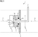
- FIG 1 shows a disc assembly 1 for a valve element.
- the disc assembly 1 provides a plunger 2.
- the plunger 2 is adapted to move along a direction indicated by arrow 3.
- the valve provides an enclosure with a guide member for the plunger 2.
- a suitable guide member such as a duct and / or bore and / or a bushing and / or a bearing in order that plunger 2 may move as indicated by arrow 3.
- seals such as O-rings to ensure fluid-tightness of the duct and / or the bore and / or the bushing and / or the bearing.
- plunger 2 has exactly one degree of freedom as indicated on FIG 1 by arrow 3.
- Outer disc 4 is ideally made of ceramics, preferably of engineering ceramics, yet more preferably of aluminum oxide (Al 2 O 3 ) and / or of silicon carbide (SiC) and / or of zirconium dioxide (ZrO 2 ) and / or of magnesium oxide (MgO).
- Al 2 O 3 aluminum oxide
- SiC silicon carbide
- ZrO 2 zirconium dioxide
- MgO magnesium oxide
- the skilled person chooses a ceramics material such as aluminum oxide with a suitable level of purity such as 92%, 96%, or 99%. Higher levels of purity confer advantages in terms of mechanical tightness, mechanical brittleness, and dielectric strength.
- movable disc 4 is coated with a suitable material such as a ceramics material.
- a suitable material such as a ceramics material.
- the coating is advantageously selected from the above list of ceramics materials.
- the coating may also be made of a diamond-like carbon layer and / or of a diamond-like carbon material.
- movable disc 4 is made of or is coated with a material with a modulus of elasticity of at least 100 GPa, preferably at least 250 GPa, yet more preferred of at least 400 GPa.
- the moveable disc 4 has a top surface and a bottom surface that define a through-hole between the two surfaces.
- One end of the plunger 2 extends through the through-hole of the disc 4.
- the disc assembly further comprises at least one O-ring disposed between the end of the plunger 2 and the disc 4.
- the at least one O-ring functions to ensure fluid is inhibited from flowing between the disc 4 and the plunger 2.
- the at least one O-ring is typically placed in between a (cylindrical) through-hole through movable disc 4 and the far end of plunger 2.
- the mechanical connection of plunger 2 to movable disc 4 advantageously comprises the at least one O-ring such as an O-ring made of (polymer) rubber.
- Plunger 2 may, by way of non-limiting example, be anchored to movable disc 4 via a bolt and / or via a friction-lock and / or via a sleeve-type joint.
- Inner disc 5 is mounted adjacent movable disc 4.
- Inner disc 5 is ideally made of ceramics, preferably of engineering ceramics, yet more preferably of aluminum oxide (Al 2 O 3 ) and / or of silicon carbide (SiC) and / or of zirconium dioxide (ZrO 2 ) and / or of magnesium oxide (MgO).
- Al 2 O 3 aluminum oxide
- SiC silicon carbide
- ZrO 2 zirconium dioxide
- MgO magnesium oxide
- the skilled person chooses a ceramics material such as aluminum oxide with a suitable level of purity such as 92%, 96%, or 99%. Higher levels of purity confer advantages in terms of mechanical tightness, mechanical brittleness, and dielectric strength.
- fixed disc 5 is coated with a suitable material such as a ceramics material.
- a suitable material such as a ceramics material.
- the coating is advantageously selected from the above list of ceramics materials.
- fixed disc 5 is made of or is coated with a material with a modulus of elasticity of at least 100 GPa, preferably at least 250 GPa, yet more preferred of at least 400 GPa.
- Inner disc 5 comprises two planar surfaces that define a duct 6a extending between the two surfaces.
- the duct 6a is sized to enable plunger 2 to extend through the duct6a .
- Duct 6a advantageously is a bore and / or a through-hole through disc 5.
- Duct 6a provides apertures on either side of inner disc 5.
- Duct 6a has a centre axis that is parallel to a connection between the apertures of duct 6a. It is envisaged that the cross-section of duct 6a around its centre axis is elliptical or substantially elliptical or rectangular or substantially rectangular.
- Duct 6a also has a length dimension 6a that is parallel to the centre axis (and also parallel to arrows 16, 17) and a cross-section diameter that is perpendicular to the centre axis.
- the length dimension of duct 6a is chosen such that plunger 2 may move in a direction that is parallel to arrow 3 and is perpendicular to the centre axis of duct 6a.
- Plunger 2 is mounted to the enclosure and / or to the housing of the valve such that any play in a direction parallel to the centre axis of duct 6a is minimized.
- the skilled person chooses a guide member that allows plunger 2 to move along directions parallel to arrow 3.
- the guide member at the same time restrains any displacement of plunger 2 in a direction parallel to the centre axis of duct 6a. That is, plunger 2 can shift movable disc 4 in directions parallel to arrow 3.
- Plunger 2 cannot shift outer disc 4 back and forth along the centre axis of duct 6a (a direction depicted by arrows 16 and 17 in FIG 1 ) so as to separate movable disc 4 from fixed disc 5.
- the housing of the valve also encloses mobile disc 4, fixed disc 5 and partition plate 9.
- plunger 2 is made of austenitic (stainless) steel. In an alternate embodiment, plunger 2 is made of ferrite steel. In yet another embodiment, plunger 2 is made of an (aluminum) alloy.
- Duct 6a provides an interface aperture 20 in the direction of movable disc 4 such that plunger 2 may connect to movable disc 4.
- a duct protruding portion 7 and / or collar 7 of fixed disc 5 surrounds the interface aperture 20 of duct 6a.
- a cross-section of protruding portion 7 in a direction perpendicular to the centre axis of duct 6a is polygonal, in particular rectangular or quadratic.
- Protruding portion 7 circumferentially surrounds the interface aperture 20 of duct 6a forming and / or defining a trough-shaped portion 8 between fixed disc 5 and movable disc 4.
- Protruding portion 7 effectively provides a rim and/or a (circumferential) wall that surrounds trough-shaped portion 8.
- Trough-shaped portion 8 is in fluid communication with duct 6a through its interface aperture 20.
- Duct protruding portion 7 has a diameter that is parallel to the diameter of duct 6a.
- the diameters of duct protruding portion 7 and of duct 6a are both perpendicular to the centre axis of duct 6a. It is envisaged that the diameter of duct protruding portion 7 exceeds the diameter of duct 6a. In an embodiment, the diameter of duct protruding portion 7 exceeds that of duct 6a at least by a factor 1.5, preferably at least by a factor 2.0, still more preferred at least by a factor 2.5.
- Protruding portion 7 provides a planar or substantially planar surface (such as a grinded and / or polished surface) that abuts an adjacent surface of movable disc 4.
- the adjacent surface of movable disc 4 is also planar or substantially planar (such as grinded and / or polished) such that abutment of the two mutually abutting surfaces yields a fluid-tight interface (such as a seal).
- any gap between the two surfaces is at most 0.58 micrometers wide, more preferably at most 0.35 micrometers wide, still more preferred at most 0.2 micrometers wide.
- Plunger 2 is advantageously aligned with disc 4 and duct protruding portion 7 so as to ensure uniform pressure between the abutting surfaces.
- duct protruding portion 7 and / or trough-shaped portion 8 are integral parts of fixed disc 5.
- protruding portion 7 and fixed disc 5 are made of the same material.
- a partition plate 9 is disposed adjacent fixed disc 5.
- Partition plate 9 has two surfaces that define a duct 6b that cooperates with duct 6a of fixed disc 5.
- Ducts 6a and 6b of fixed disc 5 and of partition plate 9 cooperate so as to define and / or provide a common duct for plunger 2.
- the common duct has a length corresponding to (associated with) the length between the opposing ends of ducts 6a and 6b (referenced herein as common duct 6a, 6b).
- a portion of plunger 2 is arranged inside the common duct.
- Duct 6b advantageously is a bore and / or a through-hole and / or a bushing through partition plate 9.
- Duct 6b provides apertures on either side of partition plate 9.
- Duct 6b has a centre axis that is parallel to a connection between the apertures of duct 6b. It is envisaged that the cross-section of duct 6b perpendicular to its centre axis is rectangular or substantially rectangular.
- Duct 6b also has a length dimension that is parallel to the centre axis (and parallel to arrows 16, 17) and a cross-section diameter that is perpendicular to its centre axis.
- the length dimension of duct 6b is chosen such that plunger 2 may move in a direction that is parallel to arrow 3 and is perpendicular to the centre axis of duct 6b.
- the symmetry axes of ducts 6a and 6b coincide or substantially coincide.
- the length dimension of duct 6b is the same or substantially the same as the length dimension of duct 6a.
- the length dimension of duct 6b is less than the length dimension of duct 6a.
- partition plate 9 is made of a metallic material such as steel, in particular austenitic (stainless) steel or ferrite steel.
- of partition plate 9 is made of aluminum (alloy).
- partition plate 9 is made of ceramics, preferably of engineering ceramics, yet more preferably of aluminum oxide (Al 2 O 3 ) and / or of silicon carbide (SiC) and / or of zirconium dioxide (ZrO 2 ) and / or of magnesium oxide (MgO).
- Al 2 O 3 aluminum oxide
- SiC silicon carbide
- ZrO 2 zirconium dioxide
- MgO magnesium oxide
- the skilled person chooses a ceramics material such as aluminum oxide with a suitable level of purity such as 92%, 96%, or 99%. Higher levels of purity confer advantages in terms of mechanical tightness, mechanical brittleness, and dielectric strength.
- partition plate 9 is coated with a suitable material such as a ceramics material.
- a suitable material such as a ceramics material.
- the coating is advantageously selected from the above list of ceramics materials.
- partition plate 9 is made of or is coated with a material with a modulus of elasticity of at least 100 GPa, preferably at least 250 GPa, yet more preferred of at least 400 GPa.
- a gasket 10 separates partition plate 9 from fixed inner disc 5 such that partition plate 9 and inner disc 5 are spaced apart. Gasket 10 seals the portion in between plate 9 and disc 5 of common duct 6a, 6b.
- gasket 10 is elliptic annular or circular annular. Gasket 10 envelopes the portion of common duct 6a, 6b, 10 in between partition plate 9 and fixed disc 5. It is also envisaged that gasket 10 is flat and / or has a cross-section that is rectangular or substantially rectangular or quadratic or substantially quadratic.
- gasket 10 is an O-ring such as an O-ring made of (polymer) rubber.
- partition plate 9 provides a groove that limits play of gasket 10.
- fixed disc 5 provides a groove that limits play of gasket 10.
- both partition plate 9 and inner disc 5 provide play-limiting grooves for gasket 10.
- Partition plate 9 also comprises a least a (cylindrical) pin 11.
- the at least one pin 11 functions to define the position of fixed disc 5 relative to partition plate 9.
- fixed disc 5 may have a recess and / or a slot that accommodates, receives, and / or mates with the far end of pin 11.
- partition plate 9 provides more than one pin to define the orientation of partition plate 9 relative to fixed disc 5.
- Pin 11 may be an integral part of partition plate 9. Pin 11 is advantageously made of the same material as partition plate 9. In an alternate embodiment, pin 11 is welded or bolted to partition plate 9.
- FIG 2 a cross-section of the same disc assembly is shown as on FIG 1 at an angle perpendicular to that of FIG 1 .
- Arrow 3 on FIG 1 points in a direction that is perpendicular to the plane of FIG 2 .
- Common duct 6a, 6b as shown on FIG 2 has a width dimension perpendicular to its centre axis and parallel to the plane of the cross-sectional view shown in FIG 2 .
- the width dimension of common duct 6a, 6b is generally less than the length dimensions of ducts 6a, 6b.
- the width dimension of common duct 6a, 6b is chosen such that it just exceeds the width of plunger 2. That is, the widths (and the walls) of common duct 6a, 6b and (the diameter) of plunger 2 cooperate to restrict or to substantially restrict the degrees of freedom of plunger 2.
- Plunger 2 may shift movable disc 4 in a direction parallel to arrow 3 of FIG 1 . Plunger 2 cannot or cannot substantially displace movable disc 4 in a direction parallel to the plane defined by the cross-sectional view of FIG 2 .
- ducts 6a and 6b have the same width dimensions. In an alternate embodiment, the width of duct 6b exceeds that of duct 6a. Accordingly, duct 6a and / or duct 6b restricts or substantially restricts the degrees of freedom of plunger 2.
- Partition plate 9 and fixed disc 5 also define and / or provide cooperating valve conduits 12b and 12a.
- Cooperating valve conduit 12b of partition plate 9 has an inner aperture directed toward fixed disc 5 and a valve port aperture on the opposite surface of plate 9. A fluid path is established between the inner aperture and the valve port aperture of conduit 12b.
- Valve conduit 12b also has a centre axis that runs from the inner aperture of conduit 12b and to the valve port aperture of conduit 12b. It is envisaged that the cross-section of cooperating valve conduit 12b perpendicular to the centre axis of conduit 12b is polygonal, in particular triangular or quadratic. In an alternate embodiment, cooperating valve conduit 12b has cylindrical symmetry.
- Cooperating valve conduit 12a of fixed disc 5 has an inner aperture 18 directed toward partition plate 9 and a valve port aperture and / or interface aperture 19 in the direction of movable disc 4. A fluid path is established between the inner aperture and the valve port aperture of conduit 12a.
- Valve conduit 12a also has a centre axis that runs from the inner aperture of conduit 12a and to the valve port aperture of conduit 12a.
- the symmetry axes of cooperating conduits 12a and 12b coincide. It is envisaged that the cross-section of cooperating valve conduit 12a perpendicular to the centre axis of conduit 12a is polygonal, in particular triangular or quadratic. In an alternate embodiment, cooperating valve conduit 12a has cylindrical symmetry. According to an aspect, the cross-section of valve conduit 12a matches the cross-section of valve conduit 12b.
- Valve conduits 12a, 12b cooperate to form a common fluid path.
- This common fluid path has a first end in the form of valve port aperture of conduit 12b of partition plate 9.
- the same common fluid path has a second end in the form of valve port aperture 19 of conduit 12a.
- the common fluid path defined by valve conduits 12a, 12b also comprises a gasket 13.
- Gasket 13 seals the portion in between plate 9 and disc 5 of this common fluid path.
- Gasket 13 is arranged in between cooperating valve conduits 12a, 12b.
- Gasket 13 is also arranged in between partition plate 9 and fixed disc 5. Gasket 13 thereby separates partition plate 9 from fixed disc 5 such that partition plate 9 and fixed disc 5 are spaced apart.
- the shape of gasket 13 is toroidal.
- gasket 13 is an O-ring such as an O-ring made of (polymer) rubber.
- partition plate 9 provides a groove that limits play of gasket 13.
- fixed disc 5 provides a groove that limits play of gasket 13.
- both partition plate 9 and inner disc 9 provide play-limiting grooves for gasket 13.
- the disc assembly 1 shown on FIG 2 corresponds to (is associated with) a valve member in an open position.
- movable disc 4 In its open position, movable disc 4 does not obturate the second end of common fluid path 12a, 12b.
- a fluid such as water may thus enter common fluid path 12a, 12b through its first aperture and leave through its second aperture and vice versa.
- valve member corresponding to (being associated with) the disc assembly 1 is shown in a closed position.
- plunger 2 has displaced movable disc 4 in a direction perpendicular to the view plane of FIGs 2 and 3 . Consequently, a portion of movable disc 4 obturates the second end of common fluid path 12a, 12b.
- a fluid such as water can no longer enter or leave common fluid path 12a, 12b through its second aperture.
- plunger 2 and (the cover portion 21 of) movable disc 4 are adapted to continuously open or close the second aperture of common fluid conduit 12a, 12b.
- plunger 2 and (the cover portion of) movable disc 4 are adapted to open or close the second aperture of common valve conduit 12a, 12b in discrete steps.
- a valve protruding portion 14 of fixed disc 5 surrounds the second aperture of common valve conduit 12a, 12b.
- a cross-section of protruding portion 14 in a direction perpendicular to the centre axis of common valve conduit 12a, 12b is polygonal, in particular quadratic.
- Valve protruding portion 14 circumferentially surrounds the second aperture of common valve conduit 12a, 12b forming and / or defining a trough-shaped portion 15 between fixed disc 5 and movable disc 4.
- Valve protruding portion 14 effectively provides a rim and / or a (circumferential) wall that surrounds trough-shaped portion 15.
- Trough-shaped portion 15 is in fluid communication with common fluid valve conduit 12a, 12b through its second aperture.
- Protruding portion 14 provides a planar or substantially planar surface (such as a grinded and / or polished surface) that abuts an adjacent surface of movable disc 4.
- the adjacent surface of movable disc 4 is also planar or substantially planar (such as grinded and / or polished) such that abutment of the two mutually abutting surfaces yields a fluid-tight interface (such as a seal).
- any gap between the two surfaces is at most 0.58 micrometers wide, more preferably at most 0.29 micrometers wide, still more preferred at most 0.2 micrometers wide.
- protruding portion 14 and / or trough-shaped portion 15 are integral parts of fixed disc 5.
- protruding portion 14 and fixed disc 5 are made of the same material.
- Valve protruding portion 14 has a diameter that is parallel to the diameter of conduit 12a.
- the diameters of protruding portion 14 and of conduit 12a are both perpendicular to the centre axis of conduit 12a. It is envisaged that the diameter of valve protruding portion 14 exceeds the diameter of conduit 12a. In an embodiment, the diameter of protruding portion 14 exceeds that of conduit 12a at least by a factor 1.5, preferably at least by a factor 2.0, still more preferred at least by a factor 2.5.
- a fluid such as water flowing in the direction indicated on FIG 1 by arrow 16 will impinge on an upstream (outbound) surface of partition plate 9.
- This direction of flow thus yields a pressure applied on an outbound surface of partition plate 9.
- That pressure applied on the effective area of the upstream surface of plate 9 causes partition plate 9 to exert a force on the housing of the assembly 1.
- the at least one gasket 10 and the at least one pin 11 mitigate transfer of deformations from the partition plate 9 to the fixed disc 5.
- the pressures applied to the mutually abutting surfaces need be sufficiently uniform to ensure fluid-tightness.
- fluid-tightness requires mutually abutting surfaces that are sufficiently even.
- the pressure applied by to the mutually abutting surfaces is at least 0.6 MPa, preferably at least 1.5 MPa, or even at least 2.5 MPa.
- any gap between the surfaces in mutual abutment is at most 0.58 micrometers wide, more preferably at most 0.29 micrometers wide, still more preferred at most 0.2 micrometers wide.
- a fluid may also impinge on disc assembly 1 from a direction 17 opposite to direction 16.
- the fluid flow in direction 17 will first reach and / or impinge on an outbound surface of movable disc 4.
- This direction 17 of flow thus yields a pressure applied on an outbound surface of movable disc 4. That pressure applied on the effective area of the upstream surface of movable disc 4 causes disc 4 to exert a force in the direction of disc 5.
- the duct protruding portion 7 and / or any valve protruding portions 14 transfer the force applied to disc 4 to fixed disc 5.
- Inner disc 5 then abuts partition plate 9. Inner disc 5 thus applies this force to partition plate 9.
- the pressure upstream of assembly 1 generally exceeds the pressure downstream of assembly 1. That is, the fluid pressure along an outbound surface of upstream disc 4 exceeds the pressure along an outbound surface of partition plate 9. No fluid would otherwise flow in direction 17 toward partition plate 9.
- Duct 6b, 6a transfers the pressure downstream of disc assembly 1 to trough-shaped portion 8. That is, the pressure inside trough-shaped portion 8 corresponds to (is associated with) the downstream pressure of assembly 1. The same downstream pressure is also applied to an end face (wall) of trough-shaped portion 8 that is part of movable disc 4. The surface area of this end face of trough-shaped portion 8 is limited by duct protruding portion 7. As downstream pressure is applied to the (effective) surface area of the end face of trough-shaped portion 8, a force is applied to movable disc 4. That force drives movable disc 4 away from fixed disc 5.
- trough-shaped portion 8 with diameters that exceed the diameter of duct protruding portion 7.
- the larger diameter of trough-shaped portion 8 compared to the diameter of duct protruding portion 7 increases the pressure-induced forces between movable disc 4 and fixed disc 5. That is, an increase in cross-section of trough-shaped portion 8 entails improved fluid-tightness. Any forces between movable disc 4 and fixed disc 5 can, in particular, be amplified by choosing a trough-shaped portion 8 or several trough-shaped portions with suitable diameters.
- the pressures applied to the mutually abutting surfaces need be sufficiently uniform to ensure fluid-tightness.
- fluid-tightness requires mutually abutting surfaces that are sufficiently planar.
- the pressure applied by to the mutually abutting surfaces is at least 0.6 MPa, preferably at least 1.5 MPa, or even at least 2.5 MPa.
- any gap between the surfaces in mutual abutment is at most 0.58 micrometers wide, more preferably at most 0.35 micrometers wide, still more preferred at most 0.2 micrometers wide.
- trough-shaped areas 15 for valve conduits 12a, 12b Similar considerations apply to trough-shaped portions 15 for valve conduits 12a, 12b. With the valve assembly in its closed position, trough-shaped portions 15 provide a suction effect similar to that of trough-shaped portion 8.
- a bracket is mounted to the far end of plunger 2 and / or to movable disc 4.
- This bracket comprises a slider that enables movement of plunger 2 and / or of movable disc 4 along the direction indicated on FIG 1 by arrow 3.
- the bracket and / or its slider also restricts or substantially restricts any degrees of freedom of the plunger 2 and / or movable disc 4 in directions perpendicular to arrow 3.
- the bracket is advantageously mounted to partition plate 9. The bracket thus defines the mutual arrangement of movable disc 4 and partition plate 9.
- Plunger 2 generally connects to an actuator for actuating (reciprocating) plunger 2.
- That actuator may, by way of non-limiting example, be a linear drive.
- a pair of wires connects to the actuator for supplying the actuator with power.
- a power meter (such as a current meter) provides a signal indicative of the power intake of the actuator.
- the power meter advantageously connects in series with the pair of wires of the actuator.
- a controller In order to monitor any open / close procedure, a controller records power intake of the actuator during open or close operations. Controller may, in particular, record power intake during open or close operations at a plurality of positions of plunger 2. These positions may include, but are not limited to, the end positions of plunger 2 as well as several positions in between the end positions of plunger 2.
- controller implements a neural network.
- the neural network comprises a plurality of input neurons that correspond to (are associated with) power intake at the various positions of plunger 2. Any input to the neural network is ideally normalized.
- the neural network also comprises an output neuron indicative of normal or of abnormal operation. According to an aspect, a value produced by output neuron of 0 indicates failure whereas an output value of 1 indicates normal operation.
- the neural network also comprises a number of hidden layers, each layer with a number of hidden neurons. In an embodiment, the neural network comprises one layer of hidden neurons. The number of neurons (perceptrons) in that layer is (approximately) double the number of input neurons for the network.
- the neurons may, by way of non-limiting example, have sigmoid and / or hyperbolic tangent and / or step-wise activation functions. The neurons are advantageously biased.
- the neural network is ideally trained under laboratory conditions. A series of measurements obtained from normal valves as well as from faulted valves is employed to train the network.
- the neural network may, by way of example, be trained by a supervised training algorithm such as backpropagation. It is also envisaged that the neural network is trained using an evolutionary algorithm such as a genetic algorithm. The skilled artisan may actually combine training algorithms.
- a genetic algorithm may, by way of example, be employed to find a coarse estimate of the weights of the connections of the neural network.
- a backpropagation algorithm is then employed to further improve on the performance of the network.
- the skilled person also pays due regard to minimizing false positives and / or false negatives. False negatives indicate a faulted valve where the disc assembly is fine. False positives indicate normal operation where the disc assembly is faulted, e.g. faulted due to (abrasive) particles.
- controller collects measurements of power intake at various positions and feeds them into the neural network.
- the neural network produces an output signal indicative of the condition of the assembly based, preferably directly based, on its inputs.
- the controller produces and signals an alarm when the valve assembly is found in faulted condition.
- the alarm may, by way of example, be dispatched via an audible signal or via a message to an operator.
- controller provides suitable interfaces. Controller may as well initiate a cleaning cycle with a plurality of open and / or close operations in order to remove particles from relevant surfaces.
- the instant disclosure teaches a disc assembly for a valve member, the disc assembly comprising:
- the interface aperture 20 has a first diameter and the trough-shaped portion 8 has a second diameter, the first diameter of the trough-shaped portion 8 exceeding the second diameter of the interface aperture 20 by a factor of at least 1.2, of at least 2.5 or of at least 5.
- the first diameter of the trough-shaped portion is at least 1 mm, preferably at least 2 mm, yet more preferred at least 5 mm.
- the collar 7 ideally protrudes at least 1 mm and / or at least 2 mm and / or at least 5 mm from the fixed disc 5.
- Plunger 2 advantageously reciprocates the movable disc 4 thereby displacing movable disc 4 laterally.
- a first pressure of a fluid applied to the movable disc 4 and to the fixed disc 5 from inside the trough-shaped portion 8 and a second pressure of a fluid applied to the movable disc 4 from outside the trough-shaped portion 8, the second pressure exceeding the first pressure are configured to apply forces to the movable disc 4 and to the fixed disc 5 that press the abutting surface of movable disc 4 against the abutting surface of the protruding collar 7 of the fixed disc 5.
- the movable disc 4 is a mobile disc.
- the movable disc 4 and the protruding collar 7 each provide surfaces in mutual abutment such that the mutually abutting surfaces of the movable disc 4 and of the protruding collar 7 form a seal, preferably a fluid-tight seal, of the trough-shaped portion 8, such that the fluid-tight seal seals the portion of the trough-shaped portion 8 in between the protruding collar 7 and the movable disc 4.
- the interface aperture 20 of the duct 6a is a mouth.
- the partition plate 9 is a flange.
- the instant disclosure also teaches one of the aforementioned disc assemblies, the disc assembly further comprising a common duct 6a, 6b, 10,
- the common duct 6a, 6b, 10 comprises the duct 6a of the fixed disc 5 and the duct 6b of the partition plate 9 and additionally comprises a portion in between the partition plate 9 and the fixed disc 5 and a gasket 10 enveloping the portion of the common duct 6a, 6b, 10 in between the partition plate 9 and the fixed disc 5; wherein the gasket 10 is interposed between the partition plate 9 and the fixed disc 5; wherein the gasket 10 seals the portion of the common duct 6a, 6b, 10 in between the partition plate 9 and the fixed disc 5.
- the plunger 2 comprises a portion enveloped by the common duct 6a, 6b, 10, wherein the enveloped portion of the plunger 2 has an axis, wherein at least one of the ducts 6a, 6b has a cross-section configured to inhibit movement of the plunger 2 in a direction that is perpendicular to the determined axis and perpendicular to the axis of the enveloped portion of the plunger 2.
- the least one of the ducts 6a, 6b has a cross-section configured to substantially prevent and / or inhibit movement of the plunger 2 and / or limit play of the plunger 2 in a direction that is perpendicular to the determined axis and perpendicular to the axis of the enveloped portion of the plunger 2.
- the instant disclosure also teaches one of the aforementioned disc assemblies, wherein the axis of the enveloped portion of the plunger 2 is perpendicular to the abutting surface of the protruding collar 7.
- the instant disclosure also teaches one of the aforementioned disc assemblies, wherein the axis of the enveloped portion of the plunger 2 is perpendicular to the abutting surface of the movable disc 4.
- the instant disclosure also teaches one of the aforementioned disc assemblies
- the at least one recess of the fixed disc 5 advantageously mates with the engaging means 11 and / or with the pin 11.
- Engaging means 11 in an embodiment is a coupling means.
- the instant disclosure also teaches one of the aforementioned disc assemblies
- Engaging means 11 advantageously is a pin.
- the at least one recess of the partition plate 9 advantageously mates with the engaging means 11 and / or with the pin 11.
- the instant disclosure also teaches one of the aforementioned disc assemblies, wherein the fixed disc 5 and the partition plate 9 each comprise at least one valve conduit 12a, 12b, the at least one valve conduit 12a of the fixed disc 5 being in fluid communication with the at least one valve conduit 12b of the partition plate 9.
- the instant disclosure also teaches one of the aforementioned disc assemblies, wherein the disc assembly further comprises at least one common valve conduit 12a, 12b, 13,
- the instant disclosure also teaches one of the aforementioned disc assemblies
- the interface aperture 19 of the at least one valve conduit 12a of the fixed disc 5 is a mouth.
- the valve collar 14 ideally protrudes at least 1 mm and / or at least 2 mm and / or at least 5 mm from the fixed disc 5.
- the interface aperture 19 of the at least one valve conduit 12a of the fixed disc 5 has a first diameter and the at least another trough-shaped portion 15 has a second diameter, the first diameter exceeding the second diameter by a factor of at least 1.2, of at least 2.5 or of at least 5.
- the first diameter of the at least one trough-shaped portion 15 is at least 1 mm, preferably at least 2 mm, yet more preferred at least 5 mm.
- the instant disclosure also teaches one of the aforementioned disc assemblies, the disc assembly further comprising at least another trough-shaped portion 15 defined and bounded by the at least one protruding valve collar 14 and by the fixed disc 5, the at least another trough-shaped portion 15 being in fluid communication with the at least one valve conduit 12a of the fixed disc 5 via the interface aperture 19 of the at least one valve conduit 12a of the fixed disc 5.
- the instant disclosure also teaches a valve member comprising one of the aforementioned disc assemblies,
- the instant disclosure also teaches a valve member comprising one of the aforementioned disc assemblies,
- the at least one cover portion 21 of the movable disc 4 uncovers the at least another trough-shaped portion 15 thereby enabling fluid flow through the at least one common valve conduit 12a, 12b, 13, wherein in the open position the surfaces for mutual abutment of the movable disc and of the at least one protruding valve collar 14 do not abut completely and / or close completely.
- cover portion 21 of the movable disc 4 is arranged at or near a far end of the movable disc 4. It is further envisaged that the cover portion 21 is an integral part of the movable disc.
- the instant disclosure also teaches a valve comprising at least one outlet and at least one inlet direction defining an upstream direction from the at least one outlet to the at least one inlet and a fluid path connecting the at least one inlet to the at least one outlet,
- the instant disclosure also teaches a valve comprising at least one inlet and at least one outlet defining a downstream direction from the at least one inlet to the at least one outlet and a fluid path connecting the at least one inlet to the at least one outlet,
- the instant disclosure also teaches a circuit for heating, ventilation and / or air conditioning with a valve and / or with a disc assembly according to the instant disclosure.
- any steps of a method according to the present disclosure may be embodied in hardware, in a software module executed by a processor, in a cloud computing arrangement, or in a combination thereof.
- the software may include a firmware, a hardware driver run in the operating system, or an application program.
- the invention also relates to a computer program product for performing the operations presented herein. If implemented in software, the functions described may be stored as one or more instructions on a computer-readable medium. Some examples of storage media that may be used include random access memory (RAM), read only memory (ROM), flash memory, EPROM memory, EEPROM memory, registers, a hard disk, a removable disk, other optical disks, or any available media that can be accessed by a computer or any other IT equipment and appliance.
- RAM random access memory
- ROM read only memory
- flash memory EPROM memory
- EEPROM memory electrically erasable programmable read-only memory
- registers a hard disk, a removable disk, other optical disks, or any available media that can be accessed
Landscapes
- Engineering & Computer Science (AREA)
- General Engineering & Computer Science (AREA)
- Mechanical Engineering (AREA)
- Sliding Valves (AREA)
Abstract
Description
- The present disclosure relates to a valve with two ceramic discs. More particularly, the present disclosure focuses on an arrangement of a pair of ceramic discs inside a housing of a valve. The present disclosure also relates to a circuit for heating, cooling, air-conditioning and / or ventilation comprising a valve with a ceramic disc.
- Valves employ ceramic discs as valve elements and / or as shut-off elements. Other uses of ceramic discs inside valves include, but are not limited to, throttle elements, elements for regulation or control of gaseous flow or liquid flow, mixing or diverting elements etc. These valves commonly comprise a metallic or a polymeric housing.
- The German patent application
DE102008017099A1 discloses a valve element with two valve plates 3a, 3b. The valve plates 3a, 3b are arranged perpendicular to flow path through the valve.FIG 1 ofDE102008017099A1 shows U-shaped valve plates 3a, 3b that may slide in opposite directions. - The German patent application
DE102008017099A1 in par 12 teachesflange inserts 9 that are made of metal or of plastics. However,DE102008017099A1 does not teach the use of ceramics in valves. The application does, in particular, not deal with difficulties with parts such as housings and throttle elements that are made of different materials. - Difficulties due to gaskets made of different materials are, however, known from various other technical fields such as wristwatches. The Japanese patent application
JP19970269073 JP19970269073 - The European patent application
EP2444702A1 discloses a valve withfixed disc 21 and with a moving disc 30. The moving disc 30 can be arranged both upstream and downstream of thefixed disc 21. In accordance with par 33, the surfaces ofdiscs 21 and 30 abut one another in order to achieve fluid-tightness. - A fluid-tight arrangement requires the abutting surfaces of the
discs 21 and 30 to be planar or substantially planar. To provide surfaces of ceramic discs that meet those requirements, the surfaces are typically grinded and / or polished during manufacture. - The arrangement disclosed in
EP2444702A1 comprises bearings 40, 41 that connect the moving disc 30 to a channel 24.FIG 3 ofEP2444702A1 depicts bearings 40, 41 that are ball-shaped. The connection between the moving disc 30 and the channel 24 also impacts on fluid-tightness, since the bearings 40, 41 transfer strains from the second channel 24 to the disc 30. The second channel 24 may, for instance, be strained as a result of thermal stresses or as a result of pressures inside and outside the valve. - To come up with a fluid-tight gasket between the
discs 21 and 30, those strains need to be reduced to a minimum. The surface of the disc 30 in contact with thedisc 21 and the opposite surface of the disc 30 in contact with the bearings 40, 41 require polishing. The requirement of ceramic discs with planar or with substantially planar surfaces adds to the cost of the valve. In addition, the ceramic material needs to be stiff in order to ensure minimum strains of the disc 30. - The present disclosure improves on valves with ceramic discs. The instant disclosure aims at providing a valve that allows technical tolerances to be relaxed.
- The present disclosure provides a disc assembly and / or a valve assembly that comprises a valve and a pair of ceramic discs. An inner ceramic disc is arranged adjacent a partition plate. The partition plate and the inner ceramic disc each provide a duct. A plunger is movably arranged in the duct and connects to an outer ceramic disc. The outer ceramic disc is arranged adjacent the inner ceramic disc such that the inner ceramic disc is interposed between the outer ceramic disc and the partition plate. The plunger may shift the outer ceramic disc relative to the inner ceramic disc and to the partition plate. The plunger does, however, allow (substantially) no displacement of the outer disc in a direction parallel to an envisaged direction of fluid flow.
- The duct through the inner ceramic disc provides an aperture in the direction of the outer ceramic disc. This aperture is surrounded by a trough-shaped area. The trough-shaped area and the outer disc enclose a fluid with a pressure that matches the pressure inside the duct. As a fluid flows in the direction of the partition plate, a pressure is applied on an outer surface of the outer disc. That pressure exceeds the pressure inside the trough-shaped area. The outer ceramic disc is then pressed against the inner ceramic disc.
- In an alternate embodiment, the partition plate is mounted (is affixed) to a valve housing. The partition plate is advantageously mounted to and / or secured relative to the same valve housing which also provides a duct (a guide element) for the plunger.
- It follows that either direction of fluid flow causes the outer disc to be pressed against the inner disc.
- The above problems are resolved by an assembly of discs and by a valve assembly in accordance with the main claims of this disclosure. Preferred embodiments of the present disclosure are covered by the dependent claims.
- It is a related object of the instant disclosure to provide a disc assembly wherein the duct comprises a gasket disposed in between the partition plate and the inner ceramic disc. The distribution of pressures along the gasket shall be as uniform as possible. The duct gasket advantageously ensures fluid tightness such that no fluid can leak from in between the inner disc and the partition plate.
- It is also an object of the instant disclosure to provide a disc assembly wherein the partition plate and the inner ceramic disc each provide a conduit. The two conduits of the partition plate and of the inner ceramic disc cooperate to form at least one common fluid path. The at least one common fluid path connects a first port of the conduit on the partition plate to a second port of the conduit of the inner disc. The second port of the inner disc terminates in the direction of the outer disc. The plunger is adapted to shift the outer disc such that a portion of the outer disc opens or closes the second port. The assembly thereby enables or obturates fluid flow through the at least one fluid path.
- It is a related object of the instant disclosure to provide a disc assembly wherein the at least one common fluid path comprises a gasket disposed in between the partition plate and the inner ceramic disc. The distribution of pressures along the at least one gasket shall be as uniform as possible. The at least one conduit path gasket advantageously ensures fluid tightness such that no fluid can leak from in between the inner disc and the partition plate.
- It is still an object of the present disclosure to provide a valve assembly and / or an arrangement of discs for a valve with a fixed disc and with a movable disc. The discs are made of a ceramic material. The discs are preferably made of engineering ceramics, yet more preferably of aluminum oxide (Al2O3) and / or of silicon carbide (SiC) and / or of zirconium dioxide (ZrO2) and / or of magnesium oxide (MgO). The skilled person chooses a ceramics material such as aluminum oxide with a suitable level of purity such as 92%, 96%, or 99%. Higher levels of purity confer advantages in terms of mechanical stiffness and strength and / or dielectric strength.
- It is still another object of the instant disclosure to provide a valve wherein the aforementioned assembly of inner (fixed) and outer (movable) discs forms a valve member. It is envisaged that the valve member ensures fluid tightness regardless of the direction of fluid flow.
- It is also an object of the instant disclosure to provide a valve assembly and / or an assembly of discs for a valve with an inner disc and with an outer disc. The inner disc provides a protrusion with a surface that abuts the surface of the outer disc. The interface formed by the abutting surfaces shall be fluid-tight or substantially fluid-tight irrespective of the direction of fluid flow.
- It is yet another object of the instant disclosure to provide a valve assembly and / or an assembly of discs for a valve with at least one gasket disposed in between the partition plate and the inner disc. The distribution of pressures along the gasket shall be as uniform as possible.
- It is a related object of the instant disclosure to provide a valve assembly and / or an assembly of discs for a valve wherein the discs are perpendicular or substantially perpendicular to the flow path through the valve.
- It is also an object of the instant disclosure to provide a valve assembly and / or an assembly of discs for a valve wherein the inner (fixed) disc and the outer (movable) disc are arranged in parallel. It is a related object of the instant disclosure to provide a valve assembly and / or an assembly of discs for a valve wherein the inner (fixed) disc and the outer (movable) disc and the partition plate are all parallel.
- The present disclosure further provides a circuit for heating, cooling, air-conditioning and / or ventilation that comprises a valve in accordance with the instant disclosure.
- Various features will become apparent to those skilled in the art from the following detailed description of the disclosed non-limiting embodiments. The drawings that accompany the detailed description can be briefly described as follows:
-
FIG 1 is a cross-section view of a disc assembly according to the present disclosure. -
FIG 2 is another cross-section view of the disc assembly in a plane perpendicular to that ofFIG 1 with a valve member of the disc assembly shown in an open position. -
FIG 3 is yet another cross-section view of the disc assembly in the same direction asFIG 2 with the valve member shown in a closed position. - The disc assembly of the instant disclosure is typically part of a valve. The valve provides an enclosure with at least one inlet and with at least one outlet. A fluid path connects the at least one inlet to the at least one outlet. A valve according to the instant disclosure also provides a valve element disposed in the fluid path. In a first position, the valve element enables fluid flow through the fluid path. In a second position, the valve element obturates fluid flow.
-
FIG 1 shows adisc assembly 1 for a valve element. Thedisc assembly 1 provides aplunger 2. Theplunger 2 is adapted to move along a direction indicated byarrow 3. It is envisaged that the valve provides an enclosure with a guide member for theplunger 2. The skilled person selects a suitable guide member such as a duct and / or bore and / or a bushing and / or a bearing in order thatplunger 2 may move as indicated byarrow 3. The skilled person also envisages seals such as O-rings to ensure fluid-tightness of the duct and / or the bore and / or the bushing and / or the bearing. - It is envisaged that
plunger 2 has exactly one degree of freedom as indicated onFIG 1 byarrow 3. -
Plunger 2 is affixed to an outer disc 4 (also referenced asmovable disc 4 herein).Outer disc 4 is ideally made of ceramics, preferably of engineering ceramics, yet more preferably of aluminum oxide (Al2O3) and / or of silicon carbide (SiC) and / or of zirconium dioxide (ZrO2) and / or of magnesium oxide (MgO). The skilled person chooses a ceramics material such as aluminum oxide with a suitable level of purity such as 92%, 96%, or 99%. Higher levels of purity confer advantages in terms of mechanical tightness, mechanical brittleness, and dielectric strength. - According to an aspect,
movable disc 4 is coated with a suitable material such as a ceramics material. The coating is advantageously selected from the above list of ceramics materials. The coating may also be made of a diamond-like carbon layer and / or of a diamond-like carbon material. - According to another aspect,
movable disc 4 is made of or is coated with a material with a modulus of elasticity of at least 100 GPa, preferably at least 250 GPa, yet more preferred of at least 400 GPa. - The
moveable disc 4 has a top surface and a bottom surface that define a through-hole between the two surfaces. One end of theplunger 2 extends through the through-hole of thedisc 4. The disc assembly further comprises at least one O-ring disposed between the end of theplunger 2 and thedisc 4. The at least one O-ring functions to ensure fluid is inhibited from flowing between thedisc 4 and theplunger 2. The at least one O-ring is typically placed in between a (cylindrical) through-hole throughmovable disc 4 and the far end ofplunger 2. The mechanical connection ofplunger 2 tomovable disc 4 advantageously comprises the at least one O-ring such as an O-ring made of (polymer) rubber.Plunger 2 may, by way of non-limiting example, be anchored tomovable disc 4 via a bolt and / or via a friction-lock and / or via a sleeve-type joint. - An
inner disc 5 is mounted adjacentmovable disc 4.Inner disc 5 is ideally made of ceramics, preferably of engineering ceramics, yet more preferably of aluminum oxide (Al2O3) and / or of silicon carbide (SiC) and / or of zirconium dioxide (ZrO2) and / or of magnesium oxide (MgO). The skilled person chooses a ceramics material such as aluminum oxide with a suitable level of purity such as 92%, 96%, or 99%. Higher levels of purity confer advantages in terms of mechanical tightness, mechanical brittleness, and dielectric strength. - According to an aspect, fixed
disc 5 is coated with a suitable material such as a ceramics material. The coating is advantageously selected from the above list of ceramics materials. - According to another aspect, fixed
disc 5 is made of or is coated with a material with a modulus of elasticity of at least 100 GPa, preferably at least 250 GPa, yet more preferred of at least 400 GPa. -
Inner disc 5 comprises two planar surfaces that define aduct 6a extending between the two surfaces. Theduct 6a is sized to enableplunger 2 to extend through the duct6a .Duct 6a advantageously is a bore and / or a through-hole throughdisc 5.Duct 6a provides apertures on either side ofinner disc 5.Duct 6a has a centre axis that is parallel to a connection between the apertures ofduct 6a. It is envisaged that the cross-section ofduct 6a around its centre axis is elliptical or substantially elliptical or rectangular or substantially rectangular.Duct 6a also has alength dimension 6a that is parallel to the centre axis (and also parallel toarrows 16, 17) and a cross-section diameter that is perpendicular to the centre axis. The length dimension ofduct 6a is chosen such thatplunger 2 may move in a direction that is parallel toarrow 3 and is perpendicular to the centre axis ofduct 6a. -
Plunger 2 is mounted to the enclosure and / or to the housing of the valve such that any play in a direction parallel to the centre axis ofduct 6a is minimized. To that end, the skilled person chooses a guide member that allowsplunger 2 to move along directions parallel toarrow 3. The guide member at the same time restrains any displacement ofplunger 2 in a direction parallel to the centre axis ofduct 6a. That is,plunger 2 can shiftmovable disc 4 in directions parallel toarrow 3.Plunger 2 cannot shiftouter disc 4 back and forth along the centre axis ofduct 6a (a direction depicted byarrows FIG 1 ) so as to separatemovable disc 4 from fixeddisc 5. It is envisaged that the housing of the valve also enclosesmobile disc 4, fixeddisc 5 andpartition plate 9. - The skilled person also chooses a material for
plunger 2 that is sufficiently stiff thereby minimizing play. In an embodiment,plunger 2 is made of austenitic (stainless) steel. In an alternate embodiment,plunger 2 is made of ferrite steel. In yet another embodiment,plunger 2 is made of an (aluminum) alloy. -
Duct 6a provides aninterface aperture 20 in the direction ofmovable disc 4 such thatplunger 2 may connect tomovable disc 4. Aduct protruding portion 7 and / orcollar 7 of fixed disc 5 (circumferentially) surrounds theinterface aperture 20 ofduct 6a. According to an aspect, a cross-section of protrudingportion 7 in a direction perpendicular to the centre axis ofduct 6a is polygonal, in particular rectangular or quadratic. - Protruding
portion 7 circumferentially surrounds theinterface aperture 20 ofduct 6a forming and / or defining a trough-shapedportion 8 between fixeddisc 5 andmovable disc 4. Protrudingportion 7 effectively provides a rim and/or a (circumferential) wall that surrounds trough-shapedportion 8. Trough-shapedportion 8 is in fluid communication withduct 6a through itsinterface aperture 20. -
Duct protruding portion 7 has a diameter that is parallel to the diameter ofduct 6a. The diameters ofduct protruding portion 7 and ofduct 6a are both perpendicular to the centre axis ofduct 6a. It is envisaged that the diameter ofduct protruding portion 7 exceeds the diameter ofduct 6a. In an embodiment, the diameter ofduct protruding portion 7 exceeds that ofduct 6a at least by a factor 1.5, preferably at least by a factor 2.0, still more preferred at least by a factor 2.5. - Protruding
portion 7 provides a planar or substantially planar surface (such as a grinded and / or polished surface) that abuts an adjacent surface ofmovable disc 4. The adjacent surface ofmovable disc 4 is also planar or substantially planar (such as grinded and / or polished) such that abutment of the two mutually abutting surfaces yields a fluid-tight interface (such as a seal). Advantageously, any gap between the two surfaces is at most 0.58 micrometers wide, more preferably at most 0.35 micrometers wide, still more preferred at most 0.2 micrometers wide.Plunger 2 is advantageously aligned withdisc 4 andduct protruding portion 7 so as to ensure uniform pressure between the abutting surfaces. - It is envisaged that
duct protruding portion 7 and / or trough-shapedportion 8 are integral parts of fixeddisc 5. Ideally, protrudingportion 7 and fixeddisc 5 are made of the same material. - A
partition plate 9 is disposed adjacent fixeddisc 5.Partition plate 9 has two surfaces that define aduct 6b that cooperates withduct 6a of fixeddisc 5.Ducts disc 5 and ofpartition plate 9 cooperate so as to define and / or provide a common duct forplunger 2. The common duct has a length corresponding to (associated with) the length between the opposing ends ofducts common duct plunger 2 is arranged inside the common duct. -
Duct 6b advantageously is a bore and / or a through-hole and / or a bushing throughpartition plate 9.Duct 6b provides apertures on either side ofpartition plate 9.Duct 6b has a centre axis that is parallel to a connection between the apertures ofduct 6b. It is envisaged that the cross-section ofduct 6b perpendicular to its centre axis is rectangular or substantially rectangular.Duct 6b also has a length dimension that is parallel to the centre axis (and parallel toarrows 16, 17) and a cross-section diameter that is perpendicular to its centre axis. The length dimension ofduct 6b is chosen such thatplunger 2 may move in a direction that is parallel toarrow 3 and is perpendicular to the centre axis ofduct 6b. In a particular embodiment, the symmetry axes ofducts duct 6b is the same or substantially the same as the length dimension ofduct 6a. In another embodiment, it is envisaged that the length dimension ofduct 6b is less than the length dimension ofduct 6a. - In an embodiment,
partition plate 9 is made of a metallic material such as steel, in particular austenitic (stainless) steel or ferrite steel. In an alternate embodiment, ofpartition plate 9 is made of aluminum (alloy). In yet another embodiment,partition plate 9 is made of ceramics, preferably of engineering ceramics, yet more preferably of aluminum oxide (Al2O3) and / or of silicon carbide (SiC) and / or of zirconium dioxide (ZrO2) and / or of magnesium oxide (MgO). The skilled person chooses a ceramics material such as aluminum oxide with a suitable level of purity such as 92%, 96%, or 99%. Higher levels of purity confer advantages in terms of mechanical tightness, mechanical brittleness, and dielectric strength. - According to an aspect,
partition plate 9 is coated with a suitable material such as a ceramics material. The coating is advantageously selected from the above list of ceramics materials. - According to another aspect,
partition plate 9 is made of or is coated with a material with a modulus of elasticity of at least 100 GPa, preferably at least 250 GPa, yet more preferred of at least 400 GPa. - A
gasket 10 separatespartition plate 9 from fixedinner disc 5 such thatpartition plate 9 andinner disc 5 are spaced apart.Gasket 10 seals the portion in betweenplate 9 anddisc 5 ofcommon duct gasket 10 is elliptic annular or circular annular.Gasket 10 envelopes the portion ofcommon duct partition plate 9 and fixeddisc 5. It is also envisaged thatgasket 10 is flat and / or has a cross-section that is rectangular or substantially rectangular or quadratic or substantially quadratic. According to a related aspect,gasket 10 is an O-ring such as an O-ring made of (polymer) rubber. It is envisaged thatpartition plate 9 provides a groove that limits play ofgasket 10. It is also envisaged that fixeddisc 5 provides a groove that limits play ofgasket 10. In a particular embodiment, bothpartition plate 9 andinner disc 5 provide play-limiting grooves forgasket 10. -
Partition plate 9 also comprises a least a (cylindrical)pin 11. The at least onepin 11 functions to define the position of fixeddisc 5 relative to partitionplate 9. To that end, fixeddisc 5 may have a recess and / or a slot that accommodates, receives, and / or mates with the far end ofpin 11. - It is envisaged that
partition plate 9 provides more than one pin to define the orientation ofpartition plate 9 relative to fixeddisc 5. -
Pin 11 may be an integral part ofpartition plate 9.Pin 11 is advantageously made of the same material aspartition plate 9. In an alternate embodiment,pin 11 is welded or bolted to partitionplate 9. - Now turning to
FIG 2 , a cross-section of the same disc assembly is shown as onFIG 1 at an angle perpendicular to that ofFIG 1 .Arrow 3 onFIG 1 points in a direction that is perpendicular to the plane ofFIG 2 . -
Common duct FIG 2 has a width dimension perpendicular to its centre axis and parallel to the plane of the cross-sectional view shown inFIG 2 . The width dimension ofcommon duct ducts common duct plunger 2. That is, the widths (and the walls) ofcommon duct plunger 2 cooperate to restrict or to substantially restrict the degrees of freedom ofplunger 2.Plunger 2 may shiftmovable disc 4 in a direction parallel toarrow 3 ofFIG 1 .Plunger 2 cannot or cannot substantially displacemovable disc 4 in a direction parallel to the plane defined by the cross-sectional view ofFIG 2 . - In an embodiment,
ducts duct 6b exceeds that ofduct 6a. Accordingly,duct 6a and / orduct 6b restricts or substantially restricts the degrees of freedom ofplunger 2. -
Partition plate 9 and fixeddisc 5 also define and / or provide cooperatingvalve conduits valve conduit 12b ofpartition plate 9 has an inner aperture directed toward fixeddisc 5 and a valve port aperture on the opposite surface ofplate 9. A fluid path is established between the inner aperture and the valve port aperture ofconduit 12b.Valve conduit 12b also has a centre axis that runs from the inner aperture ofconduit 12b and to the valve port aperture ofconduit 12b. It is envisaged that the cross-section of cooperatingvalve conduit 12b perpendicular to the centre axis ofconduit 12b is polygonal, in particular triangular or quadratic. In an alternate embodiment, cooperatingvalve conduit 12b has cylindrical symmetry. - Cooperating
valve conduit 12a of fixeddisc 5 has aninner aperture 18 directed towardpartition plate 9 and a valve port aperture and / orinterface aperture 19 in the direction ofmovable disc 4. A fluid path is established between the inner aperture and the valve port aperture ofconduit 12a.Valve conduit 12a also has a centre axis that runs from the inner aperture ofconduit 12a and to the valve port aperture ofconduit 12a. According to an aspect, the symmetry axes of cooperatingconduits valve conduit 12a perpendicular to the centre axis ofconduit 12a is polygonal, in particular triangular or quadratic. In an alternate embodiment, cooperatingvalve conduit 12a has cylindrical symmetry. According to an aspect, the cross-section ofvalve conduit 12a matches the cross-section ofvalve conduit 12b. -
Valve conduits conduit 12b ofpartition plate 9. The same common fluid path has a second end in the form ofvalve port aperture 19 ofconduit 12a. - The common fluid path defined by
valve conduits gasket 13.Gasket 13 seals the portion in betweenplate 9 anddisc 5 of this common fluid path.Gasket 13 is arranged in between cooperatingvalve conduits Gasket 13 is also arranged in betweenpartition plate 9 and fixeddisc 5.Gasket 13 thereby separatespartition plate 9 from fixeddisc 5 such thatpartition plate 9 and fixeddisc 5 are spaced apart. According to an aspect, the shape ofgasket 13 is toroidal. According to a related aspect,gasket 13 is an O-ring such as an O-ring made of (polymer) rubber. It is envisaged thatpartition plate 9 provides a groove that limits play ofgasket 13. It is also envisaged that fixeddisc 5 provides a groove that limits play ofgasket 13. In a particular embodiment, bothpartition plate 9 andinner disc 9 provide play-limiting grooves forgasket 13. - The
disc assembly 1 shown onFIG 2 corresponds to (is associated with) a valve member in an open position. In its open position,movable disc 4 does not obturate the second end of commonfluid path common fluid path - Now referring to
FIG 3 , the valve member corresponding to (being associated with) thedisc assembly 1 is shown in a closed position. In its closed position,plunger 2 has displacedmovable disc 4 in a direction perpendicular to the view plane ofFIGs 2 and 3 . Consequently, a portion ofmovable disc 4 obturates the second end of commonfluid path common fluid path - The skilled person also envisages a multitude of positions of
movable disc 4 in between a fully closed position and a fully open position of commonfluid conduit plunger 2 and (thecover portion 21 of)movable disc 4 are adapted to continuously open or close the second aperture of commonfluid conduit plunger 2 and (the cover portion of)movable disc 4 are adapted to open or close the second aperture ofcommon valve conduit - A
valve protruding portion 14 of fixed disc 5 (circumferentially) surrounds the second aperture ofcommon valve conduit portion 14 in a direction perpendicular to the centre axis ofcommon valve conduit -
Valve protruding portion 14 circumferentially surrounds the second aperture ofcommon valve conduit portion 15 between fixeddisc 5 andmovable disc 4.Valve protruding portion 14 effectively provides a rim and / or a (circumferential) wall that surrounds trough-shapedportion 15. Trough-shapedportion 15 is in fluid communication with commonfluid valve conduit - Protruding
portion 14 provides a planar or substantially planar surface (such as a grinded and / or polished surface) that abuts an adjacent surface ofmovable disc 4. The adjacent surface ofmovable disc 4 is also planar or substantially planar (such as grinded and / or polished) such that abutment of the two mutually abutting surfaces yields a fluid-tight interface (such as a seal). Advantageously, any gap between the two surfaces is at most 0.58 micrometers wide, more preferably at most 0.29 micrometers wide, still more preferred at most 0.2 micrometers wide. - It is envisaged that protruding
portion 14 and / or trough-shapedportion 15 are integral parts of fixeddisc 5. Ideally, protrudingportion 14 and fixeddisc 5 are made of the same material. -
Valve protruding portion 14 has a diameter that is parallel to the diameter ofconduit 12a. The diameters of protrudingportion 14 and ofconduit 12a are both perpendicular to the centre axis ofconduit 12a. It is envisaged that the diameter ofvalve protruding portion 14 exceeds the diameter ofconduit 12a. In an embodiment, the diameter of protrudingportion 14 exceeds that ofconduit 12a at least by a factor 1.5, preferably at least by a factor 2.0, still more preferred at least by a factor 2.5. - Considerations similar to
common valve conduit common valve conduit FIG 2 . - A fluid such as water flowing in the direction indicated on
FIG 1 byarrow 16 will impinge on an upstream (outbound) surface ofpartition plate 9. This direction of flow thus yields a pressure applied on an outbound surface ofpartition plate 9. That pressure applied on the effective area of the upstream surface ofplate 9 causespartition plate 9 to exert a force on the housing of theassembly 1. In addition, the at least onegasket 10 and the at least onepin 11 mitigate transfer of deformations from thepartition plate 9 to the fixeddisc 5. - The skilled person understands that the pressures applied to the mutually abutting surfaces need be sufficiently uniform to ensure fluid-tightness. The skilled person also understands that fluid-tightness requires mutually abutting surfaces that are sufficiently even. In a particular embodiment, the pressure applied by to the mutually abutting surfaces is at least 0.6 MPa, preferably at least 1.5 MPa, or even at least 2.5 MPa. According to an aspect, any gap between the surfaces in mutual abutment is at most 0.58 micrometers wide, more preferably at most 0.29 micrometers wide, still more preferred at most 0.2 micrometers wide.
- A fluid may also impinge on
disc assembly 1 from adirection 17 opposite todirection 16. The fluid flow indirection 17 will first reach and / or impinge on an outbound surface ofmovable disc 4. Thisdirection 17 of flow thus yields a pressure applied on an outbound surface ofmovable disc 4. That pressure applied on the effective area of the upstream surface ofmovable disc 4 causesdisc 4 to exert a force in the direction ofdisc 5. Theduct protruding portion 7 and / or anyvalve protruding portions 14 transfer the force applied todisc 4 to fixeddisc 5.Inner disc 5 then abutspartition plate 9.Inner disc 5 thus applies this force to partitionplate 9. - If a fluid flows in the direction indicated by
arrow 17 onFIG 1 , the pressure upstream ofassembly 1 generally exceeds the pressure downstream ofassembly 1. That is, the fluid pressure along an outbound surface ofupstream disc 4 exceeds the pressure along an outbound surface ofpartition plate 9. No fluid would otherwise flow indirection 17 towardpartition plate 9. -
Duct disc assembly 1 to trough-shapedportion 8. That is, the pressure inside trough-shapedportion 8 corresponds to (is associated with) the downstream pressure ofassembly 1. The same downstream pressure is also applied to an end face (wall) of trough-shapedportion 8 that is part ofmovable disc 4. The surface area of this end face of trough-shapedportion 8 is limited byduct protruding portion 7. As downstream pressure is applied to the (effective) surface area of the end face of trough-shapedportion 8, a force is applied tomovable disc 4. That force drivesmovable disc 4 away from fixeddisc 5. - Surfaces of
movable disc 4 other than the surface in abutment with protrudingportion 7 and the end face of trough-shapedportion 5 are exposed to upstream pressure. A force results from these pressures that drivesmovable disc 4 toward fixeddisc 5. This force exceeds the force from within trough-shapedportion 8, since upstream pressure exceeds downstream pressure. The sum of the forces applied tomovable disc 4 thus drivesmovable disc 4 in the direction of fixeddisc 5. In other words, a low (downstream) pressure inside trough-shapedportion 8 sucksmovable disc 4 toward fixeddisc 5. - Due to the suction effect from inside trough-shaped
portion 15, a pressure is applied between the mutually abutting surfaces ofmovable disc 4 and protrudingportion 7. Sincemovable disc 4 and protrudingportion 7 each provide surfaces in mutual abutment, no fluid can leak from trough-shapedportion 8. - The skilled person advantageously chooses trough-shaped
portion 8 with diameters that exceed the diameter ofduct protruding portion 7. The larger diameter of trough-shapedportion 8 compared to the diameter ofduct protruding portion 7 increases the pressure-induced forces betweenmovable disc 4 and fixeddisc 5. That is, an increase in cross-section of trough-shapedportion 8 entails improved fluid-tightness. Any forces betweenmovable disc 4 and fixeddisc 5 can, in particular, be amplified by choosing a trough-shapedportion 8 or several trough-shaped portions with suitable diameters. - The effect of increased pressure-induced forces is particularly relevant to
discs discs discs plunger 2 in order to compensate for additional friction between the surfaces of thediscs - The skilled person understands that the pressures applied to the mutually abutting surfaces need be sufficiently uniform to ensure fluid-tightness. The skilled person also understands that fluid-tightness requires mutually abutting surfaces that are sufficiently planar. In an embodiment, the pressure applied by to the mutually abutting surfaces is at least 0.6 MPa, preferably at least 1.5 MPa, or even at least 2.5 MPa. According to an aspect, any gap between the surfaces in mutual abutment is at most 0.58 micrometers wide, more preferably at most 0.35 micrometers wide, still more preferred at most 0.2 micrometers wide.
- Similar considerations apply to trough-shaped
areas 15 forvalve conduits portions 15 provide a suction effect similar to that of trough-shapedportion 8. - It is possible that during operation particles accumulate along the abutting surfaces of
collars movable disc 4. These particles may introduce gaps between the mutually abutting surfaces. These gaps may then lead to leakages. Particles between the mutually abutting surfaces may also result in additional or actually in reduced friction. - It is also envisaged that a bracket is mounted to the far end of
plunger 2 and / or tomovable disc 4. This bracket comprises a slider that enables movement ofplunger 2 and / or ofmovable disc 4 along the direction indicated onFIG 1 byarrow 3. The bracket and / or its slider also restricts or substantially restricts any degrees of freedom of theplunger 2 and / ormovable disc 4 in directions perpendicular toarrow 3. The bracket is advantageously mounted topartition plate 9. The bracket thus defines the mutual arrangement ofmovable disc 4 andpartition plate 9. -
Plunger 2 generally connects to an actuator for actuating (reciprocating)plunger 2. That actuator may, by way of non-limiting example, be a linear drive. A pair of wires connects to the actuator for supplying the actuator with power. - In an embodiment, a power meter (such as a current meter) provides a signal indicative of the power intake of the actuator. The power meter advantageously connects in series with the pair of wires of the actuator.
- In order to monitor any open / close procedure, a controller records power intake of the actuator during open or close operations. Controller may, in particular, record power intake during open or close operations at a plurality of positions of
plunger 2. These positions may include, but are not limited to, the end positions ofplunger 2 as well as several positions in between the end positions ofplunger 2. - In an embodiment, controller implements a neural network. The neural network comprises a plurality of input neurons that correspond to (are associated with) power intake at the various positions of
plunger 2. Any input to the neural network is ideally normalized. The neural network also comprises an output neuron indicative of normal or of abnormal operation. According to an aspect, a value produced by output neuron of 0 indicates failure whereas an output value of 1 indicates normal operation. The neural network also comprises a number of hidden layers, each layer with a number of hidden neurons. In an embodiment, the neural network comprises one layer of hidden neurons. The number of neurons (perceptrons) in that layer is (approximately) double the number of input neurons for the network. The neurons may, by way of non-limiting example, have sigmoid and / or hyperbolic tangent and / or step-wise activation functions. The neurons are advantageously biased. - The neural network is ideally trained under laboratory conditions. A series of measurements obtained from normal valves as well as from faulted valves is employed to train the network. The neural network may, by way of example, be trained by a supervised training algorithm such as backpropagation. It is also envisaged that the neural network is trained using an evolutionary algorithm such as a genetic algorithm. The skilled artisan may actually combine training algorithms. A genetic algorithm may, by way of example, be employed to find a coarse estimate of the weights of the connections of the neural network. A backpropagation algorithm is then employed to further improve on the performance of the network. The skilled person also pays due regard to minimizing false positives and / or false negatives. False negatives indicate a faulted valve where the disc assembly is fine. False positives indicate normal operation where the disc assembly is faulted, e.g. faulted due to (abrasive) particles.
- After training the configuration of the neural network and / or the weights of the connections of the neural network are saved in a memory of the valve controller. In operation controller collects measurements of power intake at various positions and feeds them into the neural network. The neural network produces an output signal indicative of the condition of the assembly based, preferably directly based, on its inputs.
- In an embodiment, the controller produces and signals an alarm when the valve assembly is found in faulted condition. The alarm may, by way of example, be dispatched via an audible signal or via a message to an operator. To that end, controller provides suitable interfaces. Controller may as well initiate a cleaning cycle with a plurality of open and / or close operations in order to remove particles from relevant surfaces.
- In other words, the instant disclosure teaches a disc assembly for a valve member, the disc assembly comprising:
- a
plunger 2 and amovable disc 4 coupled to, preferably anchored to, in an embodiment directly coupled to, in another embodiment directly anchored to, theplunger 2; - a
partition plate 9 and a fixeddisc 5 interposed between thepartition plate 9 and themovable disc 4; - wherein the fixed
disc 5 and thepartition plate 9 each comprise aduct ducts plunger 2 and at least one of theducts plunger 2 is configured to reciprocate along an axis determined by the cross-section and to reciprocate themovable disc 4 relative to the fixeddisc 5 along the determined axis; - wherein the
duct 6a of the fixeddisc 5 has and / or provides an end that defines aninterface aperture 20 having an outer circumference, theinterface aperture 20 opening in the direction of themovable disc 4; - wherein the fixed
disc 5 comprises acollar 7 protruding from the fixeddisc 5 in the direction of themovable disc 4 and looping about the outer circumference of theinterface aperture 20 of theduct 6a of the fixeddisc 5; - the disc assembly also comprising a trough-shaped
portion 8 defined and bounded by the protrudingcollar 7, by the fixeddisc 5 and by themovable disc 4, the trough-shapedportion 8 being in fluid communication with theduct 6a of the fixeddisc 5 via theinterface aperture 20; - wherein the
movable disc 4 and the protrudingcollar 7 each has a surface in mutual abutment with each other such that the mutually abutting surfaces of of themovable disc 4 and of the protrudingcollar 7 form a seal about the trough-shapedportion 8, - wherein a first pressure of a fluid applied to the
movable disc 4 from inside the trough-shapedportion 8 and a second pressure of a fluid applied to themovable disc 4 from outside the trough-shapedportion 8, the second pressure exceeding the first pressure, are configured to apply a force to themovable disc 4 that presses the abutting surface ofmovable disc 4 against the abutting surface of the protrudingcollar 7 of the fixeddisc 5. - In an embodiment, the
interface aperture 20 has a first diameter and the trough-shapedportion 8 has a second diameter, the first diameter of the trough-shapedportion 8 exceeding the second diameter of theinterface aperture 20 by a factor of at least 1.2, of at least 2.5 or of at least 5. The first diameter of the trough-shaped portion is at least 1 mm, preferably at least 2 mm, yet more preferred at least 5 mm. Thecollar 7 ideally protrudes at least 1 mm and / or at least 2 mm and / or at least 5 mm from the fixeddisc 5.Plunger 2 advantageously reciprocates themovable disc 4 thereby displacingmovable disc 4 laterally. - According to an aspect, a first pressure of a fluid applied to the
movable disc 4 and to the fixeddisc 5 from inside the trough-shapedportion 8 and a second pressure of a fluid applied to themovable disc 4 from outside the trough-shapedportion 8, the second pressure exceeding the first pressure, are configured to apply forces to themovable disc 4 and to the fixeddisc 5 that press the abutting surface ofmovable disc 4 against the abutting surface of the protrudingcollar 7 of the fixeddisc 5. In an embodiment, themovable disc 4 is a mobile disc. - It is envisaged that the
movable disc 4 and the protrudingcollar 7 each provide surfaces in mutual abutment such that the mutually abutting surfaces of themovable disc 4 and of the protrudingcollar 7 form a seal, preferably a fluid-tight seal, of the trough-shapedportion 8, such that the fluid-tight seal seals the portion of the trough-shapedportion 8 in between the protrudingcollar 7 and themovable disc 4. - In an embodiment, the
interface aperture 20 of theduct 6a is a mouth. - According to an aspect, the
partition plate 9 is a flange. - The instant disclosure also teaches one of the aforementioned disc assemblies, the disc assembly further comprising a
common duct - wherein the
common duct duct 6a of the fixeddisc 5 and theduct 6b of thepartition plate 9 and additionally comprises a portion in between thepartition plate 9 and the fixeddisc 5 and agasket 10 enveloping the portion of thecommon duct partition plate 9 and the fixeddisc 5;
wherein thegasket 10 is interposed between thepartition plate 9 and the fixeddisc 5;
wherein thegasket 10 seals the portion of thecommon duct partition plate 9 and the fixeddisc 5. - The instant disclosure also teaches one of the aforementioned disc assemblies the
plunger 2 comprises a portion enveloped by thecommon duct
wherein the enveloped portion of theplunger 2 has an axis,
wherein at least one of theducts plunger 2 in a direction that is perpendicular to the determined axis and perpendicular to the axis of the enveloped portion of theplunger 2. - It is envisaged that the least one of the
ducts plunger 2 and / or limit play of theplunger 2 in a direction that is perpendicular to the determined axis and perpendicular to the axis of the enveloped portion of theplunger 2. - The instant disclosure also teaches one of the aforementioned disc assemblies, wherein the axis of the enveloped portion of the
plunger 2 is perpendicular to the abutting surface of the protrudingcollar 7. - The instant disclosure also teaches one of the aforementioned disc assemblies, wherein the axis of the enveloped portion of the
plunger 2 is perpendicular to the abutting surface of themovable disc 4. - The instant disclosure also teaches one of the aforementioned disc assemblies,
- wherein the
partition plate 9 comprises at least one engagingmeans 11 and the fixeddisc 5 comprises at least one recess, - wherein the at least one recess of the fixed
disc 5 receives the at least one engaging means 11 of thepartition plate 9 thereby defining the position of the fixeddisc 5 relative to thepartition plate 9. - The at least one recess of the fixed
disc 5 advantageously mates with the engagingmeans 11 and / or with thepin 11. Engaging means 11 in an embodiment is a coupling means. - The instant disclosure also teaches one of the aforementioned disc assemblies,
- wherein the fixed
disc 5 comprises at least one anchorage and / or coupling means and thepartition plate 9 comprises at least one recess, - wherein the at least one recess of the
partition plate 9 receives the at least one engaging means 11 of the fixed disc thereby defining the position of thepartition plate 9 relative to the fixeddisc 5. - Engaging means 11 advantageously is a pin. The at least one recess of the
partition plate 9 advantageously mates with the engagingmeans 11 and / or with thepin 11. - The instant disclosure also teaches one of the aforementioned disc assemblies,
wherein the fixeddisc 5 and thepartition plate 9 each comprise at least onevalve conduit valve conduit 12a of the fixeddisc 5 being in fluid communication with the at least onevalve conduit 12b of thepartition plate 9. - The instant disclosure also teaches one of the aforementioned disc assemblies, wherein the disc assembly further comprises at least one
common valve conduit - wherein the at least one
common valve conduit valve conduit 12a of the fixeddisc 5 and the at least onevalve conduit 12b of thepartition plate 9 and additionally comprises a portion in between thepartition plate 9 and the fixeddisc 5 and at least onevalve gasket 13 enveloping the portion of thecommon valve conduit partition plate 9 and the fixeddisc 5, - wherein the at least one
valve gasket 13 is interposed between thepartition plate 9 and the fixeddisc 5, - wherein the at least one
valve gasket 13 seals the portion of the at least onecommon valve conduit partition plate 9 and the fixeddisc 5. - The instant disclosure also teaches one of the aforementioned disc assemblies,
- wherein the at least one
valve conduit 12a of the fixeddisc 5 has an end that defines aninterface aperture 19 having an outer circumference, theinterface aperture 19 of the at least onevalve conduit 12a of the fixeddisc 5 opening in the direction of themovable disc 4, - wherein the fixed
disc 5 comprises at least onevalve collar 14 protruding from the fixeddisc 5 in the direction of themovable disc 4 and looping about the outer circumference of theinterface aperture 19 of the at least oneconduit 12a of the fixeddisc 5. - In an embodiment, the
interface aperture 19 of the at least onevalve conduit 12a of the fixeddisc 5 is a mouth. Thevalve collar 14 ideally protrudes at least 1 mm and / or at least 2 mm and / or at least 5 mm from the fixeddisc 5. - In an embodiment, the
interface aperture 19 of the at least onevalve conduit 12a of the fixeddisc 5 has a first diameter and the at least another trough-shapedportion 15 has a second diameter, the first diameter exceeding the second diameter by a factor of at least 1.2, of at least 2.5 or of at least 5. The first diameter of the at least one trough-shapedportion 15 is at least 1 mm, preferably at least 2 mm, yet more preferred at least 5 mm. - The instant disclosure also teaches one of the aforementioned disc assemblies, the disc assembly further comprising at least another trough-shaped
portion 15 defined and bounded by the at least one protrudingvalve collar 14 and by the fixeddisc 5, the at least another trough-shapedportion 15 being in fluid communication with the at least onevalve conduit 12a of the fixeddisc 5 via theinterface aperture 19 of the at least onevalve conduit 12a of the fixeddisc 5. - The instant disclosure also teaches a valve member comprising one of the aforementioned disc assemblies,
- wherein the
movable disc 4 additionally comprises at least onecover portion 21, - wherein the at least one
cover portion 21 of themovable disc 4 and the at least one protrudingvalve collar 14 each has a surface in mutual abutment with each other, - wherein the
plunger 2 is configured to move themovable disc 4 and the at least onecover portion 21 of themovable disc 4 to a closed position - such that in the closed position the surfaces configured for mutual abutment of the at least one
cover portion 21 and of the at least one protrudingvalve collar 14 form a seal of the at least another trough-shapedportion 15 - thereby obturating fluid flow through the at least one
common valve conduit - The instant disclosure also teaches a valve member comprising one of the aforementioned disc assemblies,
- wherein the
movable disc 4 additionally comprises at least onecover portion 21, - wherein the at least one
cover portion 21 of themovable disc 4 and the at least one protrudingvalve collar 14 each has a surface in mutual abutment with each other, - wherein the
plunger 2 is configured to move themovable disc 4 and the at least onecover portion 21 of themovable disc 4 in an open position - such that in the open position the at least one
cover portion 21 of themovable disc 4 uncovers the at least another trough-shapedportion 15 thereby enabling fluid flow through the at least onecommon valve conduit - It is envisaged that in the open position the at least one
cover portion 21 of themovable disc 4 uncovers the at least another trough-shapedportion 15 thereby enabling fluid flow through the at least onecommon valve conduit valve collar 14 do not abut completely and / or close completely. - It is also envisaged that the
cover portion 21 of themovable disc 4 is arranged at or near a far end of themovable disc 4. It is further envisaged that thecover portion 21 is an integral part of the movable disc. - The instant disclosure also teaches a valve comprising at least one outlet and at least one inlet direction defining an upstream direction from the at least one outlet to the at least one inlet and a fluid path connecting the at least one inlet to the at least one outlet,
- the valve also comprising at least one aforementioned valve member,
- wherein the at least one valve member is arranged in the fluid path between the at least one inlet of the valve and the at least one outlet of the valve,
- wherein the fixed
disc 5 is arranged in the upstream direction from themovable disc 4. - The instant disclosure also teaches a valve comprising at least one inlet and at least one outlet defining a downstream direction from the at least one inlet to the at least one outlet and a fluid path connecting the at least one inlet to the at least one outlet,
- the valve also comprising at least one aforementioned valve member,
- wherein the at least one valve member is arranged in the fluid path between the at least one inlet of the valve and the at least one outlet of the valve,
- wherein the fixed
disc 5 is arranged in the downstream direction from themovable disc 4. - The instant disclosure also teaches a circuit for heating, ventilation and / or air conditioning with a valve and / or with a disc assembly according to the instant disclosure.
- Any steps of a method according to the present disclosure may be embodied in hardware, in a software module executed by a processor, in a cloud computing arrangement, or in a combination thereof. The software may include a firmware, a hardware driver run in the operating system, or an application program. Thus, the invention also relates to a computer program product for performing the operations presented herein. If implemented in software, the functions described may be stored as one or more instructions on a computer-readable medium. Some examples of storage media that may be used include random access memory (RAM), read only memory (ROM), flash memory, EPROM memory, EEPROM memory, registers, a hard disk, a removable disk, other optical disks, or any available media that can be accessed by a computer or any other IT equipment and appliance.
- It should be understood that the foregoing relates only to certain embodiments of the invention and that numerous changes may be made therein without departing the scope of the disclosure as defined by the following claims. It should also be understood that the disclosure is not restricted to the illustrated embodiments and that various modifications can be made within the scope of the following claims.
-
- 1 disc assembly
- 2 plunger
- 3 degree of freedom of
plunger 2 - 4 outer (movable) disc
- 5 inner (fixed) disc
- 6a, 6b ducts for
plunger 2 - 7 duct protruding portion (collar)
- 8 trough-shaped portion for
ducts - 9 partition plate
- 10 at least one gasket
- 11 at least one pin
- 12a, 12b valve conduits
- 13 at least one gasket
- 14 valve protruding portions (collars)
- 15 trough-shaped portion for
valve conduits - 16 first direction of fluid flow
- 17 second direction of fluid flow
- 18 inner aperture
- 19 interface aperture
- 20 interface aperture
- 21 cover portion
- 22a, 22b further valve conduits
Claims (15)
- A disc assembly for a valve member, the disc assembly comprising:a plunger (2) and a movable disc (4) coupled to the plunger (2);a partition plate (9) and a fixed disc (5) interposed between the partition plate (9) and the movable disc (4),wherein the fixed disc (5) and the partition plate (9) each comprise a duct (6a, 6b), the ducts (6a, 6b) being in fluid communication and receiving the plunger (2) and at least one of the ducts (6a, 6b) having a cross-section such that the plunger (2) is configured to reciprocate along an axis determined by the cross-section and to reciprocate the movable disc (4) relative to the fixed disc (5) along the determined axis;wherein the duct (6a) of the fixed disc (5) has an end that defines an interface aperture (20) having an outer circumference, the interface aperture (20) opening in the direction of the movable disc (4);wherein the fixed disc (5) comprises a collar (7) protruding from the fixed disc (5) in the direction of the movable disc (4) and looping about the outer circumference of the interface aperture (20) of the duct (6a) of the fixed disc (5);the disc assembly also comprising a trough-shaped portion (8) defined and bounded by the protruding collar (7), by the fixed disc (5) and by the movable disc (4), the trough-shaped portion (8) being in fluid communication with the duct (6a) of the fixed disc (5) via the interface aperture (20);wherein the movable disc (4) and the protruding collar (7) each has a surface in mutual abutment with each other such that the mutually abutting surfaces of the movable disc (4) and of the protruding collar (7) form a seal about the trough-shaped portion (8);wherein a first pressure of a fluid applied to the movable disc (4) from inside the trough-shaped portion (8) and a second pressure of a fluid applied to the movable disc (4) from outside the trough-shaped portion (8), the second pressure exceeding the first pressure, are configured to apply a force to the movable disc (4) that presses the abutting surface of movable disc (4) against the abutting surface of the protruding collar (7) of the fixed disc (5).
- The disc assembly according to claim 1, wherein the disc assembly further comprises a common duct (6a, 6b, 10),wherein the common duct (6a, 6b, 10) comprises the duct (6a) of the fixed disc (5) and the duct (6b) of the partition plate (9) and additionally comprises a portion in between the partition plate (9) and the fixed disc (5) and a gasket (10) enveloping the portion of the common duct (6a, 6b, 10) in between the partition plate (9) and the fixed disc (5);wherein the gasket (10) is interposed between the partition plate (9) and the fixed disc (5);wherein the gasket (10) seals the portion of the common duct (6a, 6b, 10) in between the partition plate (9) and the fixed disc (5).
- The disc assembly according to claim 2wherein the plunger (2) comprises a portion enveloped by the common duct (6a, 6b, 10),wherein the enveloped portion of the plunger (2) has an axis,wherein at least one of the ducts (6a, 6b) has a cross-section configured to inhibit movement of the plunger (2) in a direction that is perpendicular to the determined axis and perpendicular to the axis of the enveloped portion of the plunger (2).
- The disc assembly according to claim 3, wherein the axis of the enveloped portion of the plunger (2) is perpendicular to the abutting surface of the protruding collar (7).
- The disc assembly according to any of the claims 3 to 4, wherein the axis of the enveloped portion of the plunger (2) is perpendicular to the abutting surface of the movable disc (4).
- The disc assembly according to any of the claims 1 to 5,wherein the partition plate (9) comprises at least one engaging means (11) and the fixed disc (5) comprises at least one recess,wherein the at least one recess of the fixed disc (5) receives the at least one engaging means (11) of the partition plate (9) thereby defining the position of the fixed disc (5) relative to the partition plate (9).
- The disc assembly according to any of the claims 1 to 6,wherein the fixed disc (5) comprises at least one engaging means and the partition plate (9) comprises at least one recess;wherein the at least one recess of the partition plate (9) receives the at least one engaging means (11) of the fixed disc thereby defining the position of the partition plate (9) relative to the fixed disc (5).
- The disc assembly according to any of the claims 1 to 7,
wherein the fixed disc (5) and the partition plate (9) each comprise at least one valve conduit (12a, 12b), the at least one valve conduit (12a) of the fixed disc (5) being in fluid communication with the at least one valve conduit (12b) of the partition plate (9). - The disc assembly according to claim 8, the disc assembly further comprising at least one common valve conduit (12a, 12b, 13),wherein the at least one common valve conduit (12a, 12b, 13) comprises the at least one valve conduit (12a) of the fixed disc (5) and the at least one valve conduit (12b) of the partition plate (9) and additionally comprises a portion in between the partition plate (9) and the fixed disc (5) and at least one valve gasket (13) enveloping the portion of the common valve conduit (12a, 12b, 13) in between the partition plate (9) and the fixed disc (5);wherein the at least one valve gasket (13) is interposed between the partition plate (9) and the fixed disc (5);wherein the at least one valve gasket (13) seals the portion of the at least one common valve conduit (12a, 12b, 13) in between the partition plate (9) and the fixed disc (5).
- The disc assembly according to any of the claims 8 or 9,wherein the at least one valve conduit (12a) of the fixed disc (5) has an end that defines an interface aperture (19) having an outer circumference, the interface aperture (19) of the at least one valve conduit (12a) of the fixed disc (5) opening in the direction of the movable disc (4);wherein the fixed disc (5) comprises at least one valve collar (14) protruding from the fixed disc (5) in the direction of the movable disc (4) and looping about the outer circumference of the interface aperture (19) of the at least one conduit (12a) of the fixed disc (5).
- The disc assembly according to claim 10, the disc assembly further comprising at least another trough-shaped portion (15) defined and bounded by the at least one protruding valve collar (14) and by the fixed disc (5), the at least another trough-shaped portion (15) being in fluid communication with the at least one valve conduit (12a) of the fixed disc (5) via the interface aperture (19) of the at least one valve conduit (12a) of the fixed disc (5).
- A valve member comprising the disc assembly according to claim 11,wherein the movable disc (4) additionally comprises at least one cover portion (21);wherein the at least one cover portion (21) of the movable disc (4) and the at least one protruding valve collar (14) each has a surface in mutual abutment with each other;wherein the plunger (2) is configured to move the movable disc (4) and the at least one cover portion (21) of the movable disc (4) to a closed positionsuch that in the closed position the surfaces configured for mutual abutment of the at least one cover portion (21) and of the at least one protruding valve collar (14) form a seal of the at least another trough-shaped portion (15)thereby obturating fluid flow through the at least one common valve conduit (12a, 12b, 13).
- A valve member comprising the disc assembly according to claim 11,wherein the movable disc (4) additionally comprises at least one cover portion (21),wherein the at least one cover portion (21) of the movable disc (4) and the at least one protruding valve collar (14) each has a surface in mutual abutment with each other;wherein the plunger (2) is configured to move the movable disc (4) and the at least one cover portion (21) of the movable disc (4) in an open positionsuch that in the open position the at least one cover portion (21) of the movable disc (4) uncovers the at least another trough-shaped portion (15) thereby enabling fluid flow through the at least one common valve conduit (12a, 12b, 13).
- A valve comprising at least one outlet and at least one inlet defining an upstream direction from the at least one outlet to the at least one inlet and a fluid path connecting the at least one inlet to the at least one outlet,the valve also comprising at least one valve member according to any of the claims 12 to 13;wherein the at least one valve member is arranged in the fluid path between the at least one inlet of the valve and the at least one outlet of the valve;wherein the fixed disc (5) is arranged in the upstream direction from the movable disc (4).
- A valve comprising at least one inlet and at least one outlet defining a downstream direction from the at least one inlet to the at least one outlet and a fluid path connecting the at least one inlet to the at least one outlet;the valve also comprising at least one valve member according to any of the claims 12 to 13;wherein the at least one valve member is arranged in the fluid path between the at least one inlet of the valve and the at least one outlet of the valve;wherein the fixed disc (5) is arranged in the downstream direction from the movable disc (4).
Priority Applications (2)
| Application Number | Priority Date | Filing Date | Title |
|---|---|---|---|
| DK17197625.1T DK3473901T3 (en) | 2017-10-20 | 2017-10-20 | disk assembly |
| EP17197625.1A EP3473901B1 (en) | 2017-10-20 | 2017-10-20 | Disc assembly |
Applications Claiming Priority (1)
| Application Number | Priority Date | Filing Date | Title |
|---|---|---|---|
| EP17197625.1A EP3473901B1 (en) | 2017-10-20 | 2017-10-20 | Disc assembly |
Publications (2)
| Publication Number | Publication Date |
|---|---|
| EP3473901A1 true EP3473901A1 (en) | 2019-04-24 |
| EP3473901B1 EP3473901B1 (en) | 2020-03-18 |
Family
ID=60153209
Family Applications (1)
| Application Number | Title | Priority Date | Filing Date |
|---|---|---|---|
| EP17197625.1A Active EP3473901B1 (en) | 2017-10-20 | 2017-10-20 | Disc assembly |
Country Status (2)
| Country | Link |
|---|---|
| EP (1) | EP3473901B1 (en) |
| DK (1) | DK3473901T3 (en) |
Citations (2)
| Publication number | Priority date | Publication date | Assignee | Title |
|---|---|---|---|---|
| DE102008017099A1 (en) | 2008-04-02 | 2009-10-15 | Torsten Burgmer | Flat slide valve has slide valve housing and two slide valve plates guided in slide valve housing transverse to flow channel, where connecting flanges are arranged on both sides of slide valve housing |
| EP2444702A1 (en) | 2010-10-19 | 2012-04-25 | Siemens Aktiengesellschaft | Gate valve with a fixed and a mobile disc for blocking and/or regulating a fluid |
-
2017
- 2017-10-20 DK DK17197625.1T patent/DK3473901T3/en active
- 2017-10-20 EP EP17197625.1A patent/EP3473901B1/en active Active
Patent Citations (2)
| Publication number | Priority date | Publication date | Assignee | Title |
|---|---|---|---|---|
| DE102008017099A1 (en) | 2008-04-02 | 2009-10-15 | Torsten Burgmer | Flat slide valve has slide valve housing and two slide valve plates guided in slide valve housing transverse to flow channel, where connecting flanges are arranged on both sides of slide valve housing |
| EP2444702A1 (en) | 2010-10-19 | 2012-04-25 | Siemens Aktiengesellschaft | Gate valve with a fixed and a mobile disc for blocking and/or regulating a fluid |
Also Published As
| Publication number | Publication date |
|---|---|
| EP3473901B1 (en) | 2020-03-18 |
| DK3473901T3 (en) | 2020-05-25 |
Similar Documents
| Publication | Publication Date | Title |
|---|---|---|
| US4174728A (en) | Sliding-gate valve | |
| KR102024951B1 (en) | Pressure-balanced fluid pressure regulators | |
| KR102047557B1 (en) | Ball valve | |
| US3401914A (en) | Fluid controlling valves | |
| JP4298476B2 (en) | Fluid control device | |
| JP4485781B2 (en) | Valve with pressure balancing piston and method related thereto | |
| JP5636301B2 (en) | Valve seat body and valve device | |
| EP2619494B1 (en) | Bonnet apparatus to provide live-loading to a seal | |
| JP6294892B2 (en) | Apparatus and method for reducing actuator thrust requirements in control valves | |
| JPH0527791B2 (en) | ||
| CN101995276B (en) | Electromagnetic Flowmeter | |
| EP2772671A1 (en) | Seal assembly for use with valves having a two-piece cage | |
| CN102449367A (en) | Valve trim apparatus for use with valves | |
| TWI794389B (en) | butterfly valve | |
| US20200056722A1 (en) | Vacuum valve comprising a force sensor | |
| US20060049375A1 (en) | Boronized valve seal | |
| JPH0193674A (en) | Valve | |
| CN101365902B (en) | Flexible seals for process control valves | |
| US4838312A (en) | Three-way valve | |
| CN101625027B (en) | Metal sealing gasket and regulating valve | |
| EP3473901B1 (en) | Disc assembly | |
| US4515347A (en) | Valve seat structure | |
| JP2017530319A (en) | Balanced double seat ball valve with flexible plug | |
| CN103765061B (en) | The black box that a kind of bellows for rotary control valve encourages | |
| JP7254467B2 (en) | Adjusting overtravel in a two-part plug for use in a valve assembly |
Legal Events
| Date | Code | Title | Description |
|---|---|---|---|
| PUAI | Public reference made under article 153(3) epc to a published international application that has entered the european phase |
Free format text: ORIGINAL CODE: 0009012 |
|
| STAA | Information on the status of an ep patent application or granted ep patent |
Free format text: STATUS: THE APPLICATION HAS BEEN PUBLISHED |
|
| AK | Designated contracting states |
Kind code of ref document: A1 Designated state(s): AL AT BE BG CH CY CZ DE DK EE ES FI FR GB GR HR HU IE IS IT LI LT LU LV MC MK MT NL NO PL PT RO RS SE SI SK SM TR |
|
| AX | Request for extension of the european patent |
Extension state: BA ME |
|
| STAA | Information on the status of an ep patent application or granted ep patent |
Free format text: STATUS: REQUEST FOR EXAMINATION WAS MADE |
|
| GRAP | Despatch of communication of intention to grant a patent |
Free format text: ORIGINAL CODE: EPIDOSNIGR1 |
|
| STAA | Information on the status of an ep patent application or granted ep patent |
Free format text: STATUS: GRANT OF PATENT IS INTENDED |
|
| 17P | Request for examination filed |
Effective date: 20190919 |
|
| RBV | Designated contracting states (corrected) |
Designated state(s): AL AT BE BG CH CY CZ DE DK EE ES FI FR GB GR HR HU IE IS IT LI LT LU LV MC MK MT NL NO PL PT RO RS SE SI SK SM TR |
|
| RIC1 | Information provided on ipc code assigned before grant |
Ipc: F16K 3/02 20060101AFI20191001BHEP Ipc: F16K 11/065 20060101ALI20191001BHEP |
|
| INTG | Intention to grant announced |
Effective date: 20191016 |
|
| GRAS | Grant fee paid |
Free format text: ORIGINAL CODE: EPIDOSNIGR3 |
|
| GRAA | (expected) grant |
Free format text: ORIGINAL CODE: 0009210 |
|
| STAA | Information on the status of an ep patent application or granted ep patent |
Free format text: STATUS: THE PATENT HAS BEEN GRANTED |
|
| AK | Designated contracting states |
Kind code of ref document: B1 Designated state(s): AL AT BE BG CH CY CZ DE DK EE ES FI FR GB GR HR HU IE IS IT LI LT LU LV MC MK MT NL NO PL PT RO RS SE SI SK SM TR |
|
| REG | Reference to a national code |
Ref country code: GB Ref legal event code: FG4D |
|
| REG | Reference to a national code |
Ref country code: DE Ref legal event code: R096 Ref document number: 602017013188 Country of ref document: DE |
|
| REG | Reference to a national code |
Ref country code: AT Ref legal event code: REF Ref document number: 1246271 Country of ref document: AT Kind code of ref document: T Effective date: 20200415 Ref country code: IE Ref legal event code: FG4D |
|
| REG | Reference to a national code |
Ref country code: CH Ref legal event code: NV Representative=s name: SIEMENS SCHWEIZ AG, CH |
|
| REG | Reference to a national code |
Ref country code: DK Ref legal event code: T3 Effective date: 20200520 |
|
| PG25 | Lapsed in a contracting state [announced via postgrant information from national office to epo] |
Ref country code: FI Free format text: LAPSE BECAUSE OF FAILURE TO SUBMIT A TRANSLATION OF THE DESCRIPTION OR TO PAY THE FEE WITHIN THE PRESCRIBED TIME-LIMIT Effective date: 20200318 Ref country code: NO Free format text: LAPSE BECAUSE OF FAILURE TO SUBMIT A TRANSLATION OF THE DESCRIPTION OR TO PAY THE FEE WITHIN THE PRESCRIBED TIME-LIMIT Effective date: 20200618 Ref country code: RS Free format text: LAPSE BECAUSE OF FAILURE TO SUBMIT A TRANSLATION OF THE DESCRIPTION OR TO PAY THE FEE WITHIN THE PRESCRIBED TIME-LIMIT Effective date: 20200318 |
|
| REG | Reference to a national code |
Ref country code: NL Ref legal event code: MP Effective date: 20200318 |
|
| PG25 | Lapsed in a contracting state [announced via postgrant information from national office to epo] |
Ref country code: LV Free format text: LAPSE BECAUSE OF FAILURE TO SUBMIT A TRANSLATION OF THE DESCRIPTION OR TO PAY THE FEE WITHIN THE PRESCRIBED TIME-LIMIT Effective date: 20200318 Ref country code: SE Free format text: LAPSE BECAUSE OF FAILURE TO SUBMIT A TRANSLATION OF THE DESCRIPTION OR TO PAY THE FEE WITHIN THE PRESCRIBED TIME-LIMIT Effective date: 20200318 Ref country code: GR Free format text: LAPSE BECAUSE OF FAILURE TO SUBMIT A TRANSLATION OF THE DESCRIPTION OR TO PAY THE FEE WITHIN THE PRESCRIBED TIME-LIMIT Effective date: 20200619 Ref country code: HR Free format text: LAPSE BECAUSE OF FAILURE TO SUBMIT A TRANSLATION OF THE DESCRIPTION OR TO PAY THE FEE WITHIN THE PRESCRIBED TIME-LIMIT Effective date: 20200318 Ref country code: BG Free format text: LAPSE BECAUSE OF FAILURE TO SUBMIT A TRANSLATION OF THE DESCRIPTION OR TO PAY THE FEE WITHIN THE PRESCRIBED TIME-LIMIT Effective date: 20200618 |
|
| REG | Reference to a national code |
Ref country code: LT Ref legal event code: MG4D |
|
| PG25 | Lapsed in a contracting state [announced via postgrant information from national office to epo] |
Ref country code: NL Free format text: LAPSE BECAUSE OF FAILURE TO SUBMIT A TRANSLATION OF THE DESCRIPTION OR TO PAY THE FEE WITHIN THE PRESCRIBED TIME-LIMIT Effective date: 20200318 |
|
| PG25 | Lapsed in a contracting state [announced via postgrant information from national office to epo] |
Ref country code: SM Free format text: LAPSE BECAUSE OF FAILURE TO SUBMIT A TRANSLATION OF THE DESCRIPTION OR TO PAY THE FEE WITHIN THE PRESCRIBED TIME-LIMIT Effective date: 20200318 Ref country code: EE Free format text: LAPSE BECAUSE OF FAILURE TO SUBMIT A TRANSLATION OF THE DESCRIPTION OR TO PAY THE FEE WITHIN THE PRESCRIBED TIME-LIMIT Effective date: 20200318 Ref country code: PT Free format text: LAPSE BECAUSE OF FAILURE TO SUBMIT A TRANSLATION OF THE DESCRIPTION OR TO PAY THE FEE WITHIN THE PRESCRIBED TIME-LIMIT Effective date: 20200812 Ref country code: RO Free format text: LAPSE BECAUSE OF FAILURE TO SUBMIT A TRANSLATION OF THE DESCRIPTION OR TO PAY THE FEE WITHIN THE PRESCRIBED TIME-LIMIT Effective date: 20200318 Ref country code: CZ Free format text: LAPSE BECAUSE OF FAILURE TO SUBMIT A TRANSLATION OF THE DESCRIPTION OR TO PAY THE FEE WITHIN THE PRESCRIBED TIME-LIMIT Effective date: 20200318 Ref country code: LT Free format text: LAPSE BECAUSE OF FAILURE TO SUBMIT A TRANSLATION OF THE DESCRIPTION OR TO PAY THE FEE WITHIN THE PRESCRIBED TIME-LIMIT Effective date: 20200318 Ref country code: SK Free format text: LAPSE BECAUSE OF FAILURE TO SUBMIT A TRANSLATION OF THE DESCRIPTION OR TO PAY THE FEE WITHIN THE PRESCRIBED TIME-LIMIT Effective date: 20200318 Ref country code: IS Free format text: LAPSE BECAUSE OF FAILURE TO SUBMIT A TRANSLATION OF THE DESCRIPTION OR TO PAY THE FEE WITHIN THE PRESCRIBED TIME-LIMIT Effective date: 20200718 |
|
| REG | Reference to a national code |
Ref country code: AT Ref legal event code: MK05 Ref document number: 1246271 Country of ref document: AT Kind code of ref document: T Effective date: 20200318 |
|
| REG | Reference to a national code |
Ref country code: DE Ref legal event code: R097 Ref document number: 602017013188 Country of ref document: DE |
|
| PLBE | No opposition filed within time limit |
Free format text: ORIGINAL CODE: 0009261 |
|
| STAA | Information on the status of an ep patent application or granted ep patent |
Free format text: STATUS: NO OPPOSITION FILED WITHIN TIME LIMIT |
|
| PG25 | Lapsed in a contracting state [announced via postgrant information from national office to epo] |
Ref country code: ES Free format text: LAPSE BECAUSE OF FAILURE TO SUBMIT A TRANSLATION OF THE DESCRIPTION OR TO PAY THE FEE WITHIN THE PRESCRIBED TIME-LIMIT Effective date: 20200318 Ref country code: AT Free format text: LAPSE BECAUSE OF FAILURE TO SUBMIT A TRANSLATION OF THE DESCRIPTION OR TO PAY THE FEE WITHIN THE PRESCRIBED TIME-LIMIT Effective date: 20200318 |
|
| 26N | No opposition filed |
Effective date: 20201221 |
|
| PG25 | Lapsed in a contracting state [announced via postgrant information from national office to epo] |
Ref country code: PL Free format text: LAPSE BECAUSE OF FAILURE TO SUBMIT A TRANSLATION OF THE DESCRIPTION OR TO PAY THE FEE WITHIN THE PRESCRIBED TIME-LIMIT Effective date: 20200318 |
|
| PGFP | Annual fee paid to national office [announced via postgrant information from national office to epo] |
Ref country code: CH Payment date: 20210104 Year of fee payment: 4 |
|
| PG25 | Lapsed in a contracting state [announced via postgrant information from national office to epo] |
Ref country code: SI Free format text: LAPSE BECAUSE OF FAILURE TO SUBMIT A TRANSLATION OF THE DESCRIPTION OR TO PAY THE FEE WITHIN THE PRESCRIBED TIME-LIMIT Effective date: 20200318 |
|
| PGFP | Annual fee paid to national office [announced via postgrant information from national office to epo] |
Ref country code: DE Payment date: 20201218 Year of fee payment: 4 |
|
| PG25 | Lapsed in a contracting state [announced via postgrant information from national office to epo] |
Ref country code: MC Free format text: LAPSE BECAUSE OF FAILURE TO SUBMIT A TRANSLATION OF THE DESCRIPTION OR TO PAY THE FEE WITHIN THE PRESCRIBED TIME-LIMIT Effective date: 20200318 Ref country code: LU Free format text: LAPSE BECAUSE OF NON-PAYMENT OF DUE FEES Effective date: 20201020 |
|
| REG | Reference to a national code |
Ref country code: BE Ref legal event code: MM Effective date: 20201031 |
|
| PG25 | Lapsed in a contracting state [announced via postgrant information from national office to epo] |
Ref country code: BE Free format text: LAPSE BECAUSE OF NON-PAYMENT OF DUE FEES Effective date: 20201031 |
|
| PG25 | Lapsed in a contracting state [announced via postgrant information from national office to epo] |
Ref country code: IE Free format text: LAPSE BECAUSE OF NON-PAYMENT OF DUE FEES Effective date: 20201020 |
|
| PGFP | Annual fee paid to national office [announced via postgrant information from national office to epo] |
Ref country code: DK Payment date: 20211022 Year of fee payment: 5 |
|
| PGFP | Annual fee paid to national office [announced via postgrant information from national office to epo] |
Ref country code: IT Payment date: 20211022 Year of fee payment: 5 Ref country code: FR Payment date: 20211020 Year of fee payment: 5 |
|
| REG | Reference to a national code |
Ref country code: DE Ref legal event code: R119 Ref document number: 602017013188 Country of ref document: DE |
|
| REG | Reference to a national code |
Ref country code: CH Ref legal event code: PL |
|
| PG25 | Lapsed in a contracting state [announced via postgrant information from national office to epo] |
Ref country code: TR Free format text: LAPSE BECAUSE OF FAILURE TO SUBMIT A TRANSLATION OF THE DESCRIPTION OR TO PAY THE FEE WITHIN THE PRESCRIBED TIME-LIMIT Effective date: 20200318 Ref country code: MT Free format text: LAPSE BECAUSE OF FAILURE TO SUBMIT A TRANSLATION OF THE DESCRIPTION OR TO PAY THE FEE WITHIN THE PRESCRIBED TIME-LIMIT Effective date: 20200318 Ref country code: CY Free format text: LAPSE BECAUSE OF FAILURE TO SUBMIT A TRANSLATION OF THE DESCRIPTION OR TO PAY THE FEE WITHIN THE PRESCRIBED TIME-LIMIT Effective date: 20200318 |
|
| GBPC | Gb: european patent ceased through non-payment of renewal fee |
Effective date: 20211020 |
|
| PG25 | Lapsed in a contracting state [announced via postgrant information from national office to epo] |
Ref country code: MK Free format text: LAPSE BECAUSE OF FAILURE TO SUBMIT A TRANSLATION OF THE DESCRIPTION OR TO PAY THE FEE WITHIN THE PRESCRIBED TIME-LIMIT Effective date: 20200318 Ref country code: AL Free format text: LAPSE BECAUSE OF FAILURE TO SUBMIT A TRANSLATION OF THE DESCRIPTION OR TO PAY THE FEE WITHIN THE PRESCRIBED TIME-LIMIT Effective date: 20200318 |
|
| PG25 | Lapsed in a contracting state [announced via postgrant information from national office to epo] |
Ref country code: GB Free format text: LAPSE BECAUSE OF NON-PAYMENT OF DUE FEES Effective date: 20211020 Ref country code: DE Free format text: LAPSE BECAUSE OF NON-PAYMENT OF DUE FEES Effective date: 20220503 |
|
| PG25 | Lapsed in a contracting state [announced via postgrant information from national office to epo] |
Ref country code: LI Free format text: LAPSE BECAUSE OF NON-PAYMENT OF DUE FEES Effective date: 20211031 Ref country code: CH Free format text: LAPSE BECAUSE OF NON-PAYMENT OF DUE FEES Effective date: 20211031 |
|
| REG | Reference to a national code |
Ref country code: DK Ref legal event code: EBP Effective date: 20221031 |
|
| PG25 | Lapsed in a contracting state [announced via postgrant information from national office to epo] |
Ref country code: FR Free format text: LAPSE BECAUSE OF NON-PAYMENT OF DUE FEES Effective date: 20221031 |
|
| PG25 | Lapsed in a contracting state [announced via postgrant information from national office to epo] |
Ref country code: IT Free format text: LAPSE BECAUSE OF NON-PAYMENT OF DUE FEES Effective date: 20221020 Ref country code: DK Free format text: LAPSE BECAUSE OF NON-PAYMENT OF DUE FEES Effective date: 20221031 |