EP3473875A1 - Tilting pad journal bearing manufacturing method, tilting pad journal bearing, and compressor - Google Patents
Tilting pad journal bearing manufacturing method, tilting pad journal bearing, and compressor Download PDFInfo
- Publication number
- EP3473875A1 EP3473875A1 EP17879678.5A EP17879678A EP3473875A1 EP 3473875 A1 EP3473875 A1 EP 3473875A1 EP 17879678 A EP17879678 A EP 17879678A EP 3473875 A1 EP3473875 A1 EP 3473875A1
- Authority
- EP
- European Patent Office
- Prior art keywords
- tilting pad
- circumferential surface
- rotary shaft
- pivot
- journal bearing
- Prior art date
- Legal status (The legal status is an assumption and is not a legal conclusion. Google has not performed a legal analysis and makes no representation as to the accuracy of the status listed.)
- Granted
Links
Images



Classifications
-
- F—MECHANICAL ENGINEERING; LIGHTING; HEATING; WEAPONS; BLASTING
- F16—ENGINEERING ELEMENTS AND UNITS; GENERAL MEASURES FOR PRODUCING AND MAINTAINING EFFECTIVE FUNCTIONING OF MACHINES OR INSTALLATIONS; THERMAL INSULATION IN GENERAL
- F16C—SHAFTS; FLEXIBLE SHAFTS; ELEMENTS OR CRANKSHAFT MECHANISMS; ROTARY BODIES OTHER THAN GEARING ELEMENTS; BEARINGS
- F16C43/00—Assembling bearings
- F16C43/02—Assembling sliding-contact bearings
-
- F—MECHANICAL ENGINEERING; LIGHTING; HEATING; WEAPONS; BLASTING
- F16—ENGINEERING ELEMENTS AND UNITS; GENERAL MEASURES FOR PRODUCING AND MAINTAINING EFFECTIVE FUNCTIONING OF MACHINES OR INSTALLATIONS; THERMAL INSULATION IN GENERAL
- F16C—SHAFTS; FLEXIBLE SHAFTS; ELEMENTS OR CRANKSHAFT MECHANISMS; ROTARY BODIES OTHER THAN GEARING ELEMENTS; BEARINGS
- F16C17/00—Sliding-contact bearings for exclusively rotary movement
- F16C17/02—Sliding-contact bearings for exclusively rotary movement for radial load only
- F16C17/03—Sliding-contact bearings for exclusively rotary movement for radial load only with tiltably-supported segments, e.g. Michell bearings
-
- F—MECHANICAL ENGINEERING; LIGHTING; HEATING; WEAPONS; BLASTING
- F01—MACHINES OR ENGINES IN GENERAL; ENGINE PLANTS IN GENERAL; STEAM ENGINES
- F01D—NON-POSITIVE DISPLACEMENT MACHINES OR ENGINES, e.g. STEAM TURBINES
- F01D25/00—Component parts, details, or accessories, not provided for in, or of interest apart from, other groups
- F01D25/18—Lubricating arrangements
- F01D25/22—Lubricating arrangements using working-fluid or other gaseous fluid as lubricant
-
- F—MECHANICAL ENGINEERING; LIGHTING; HEATING; WEAPONS; BLASTING
- F04—POSITIVE - DISPLACEMENT MACHINES FOR LIQUIDS; PUMPS FOR LIQUIDS OR ELASTIC FLUIDS
- F04D—NON-POSITIVE-DISPLACEMENT PUMPS
- F04D29/00—Details, component parts, or accessories
- F04D29/05—Shafts or bearings, or assemblies thereof, specially adapted for elastic fluid pumps
- F04D29/056—Bearings
- F04D29/057—Bearings hydrostatic; hydrodynamic
-
- F—MECHANICAL ENGINEERING; LIGHTING; HEATING; WEAPONS; BLASTING
- F16—ENGINEERING ELEMENTS AND UNITS; GENERAL MEASURES FOR PRODUCING AND MAINTAINING EFFECTIVE FUNCTIONING OF MACHINES OR INSTALLATIONS; THERMAL INSULATION IN GENERAL
- F16C—SHAFTS; FLEXIBLE SHAFTS; ELEMENTS OR CRANKSHAFT MECHANISMS; ROTARY BODIES OTHER THAN GEARING ELEMENTS; BEARINGS
- F16C33/00—Parts of bearings; Special methods for making bearings or parts thereof
- F16C33/02—Parts of sliding-contact bearings
- F16C33/04—Brasses; Bushes; Linings
- F16C33/20—Sliding surface consisting mainly of plastics
- F16C33/208—Methods of manufacture, e.g. shaping, applying coatings
-
- F—MECHANICAL ENGINEERING; LIGHTING; HEATING; WEAPONS; BLASTING
- F05—INDEXING SCHEMES RELATING TO ENGINES OR PUMPS IN VARIOUS SUBCLASSES OF CLASSES F01-F04
- F05D—INDEXING SCHEME FOR ASPECTS RELATING TO NON-POSITIVE-DISPLACEMENT MACHINES OR ENGINES, GAS-TURBINES OR JET-PROPULSION PLANTS
- F05D2220/00—Application
- F05D2220/40—Application in turbochargers
-
- F—MECHANICAL ENGINEERING; LIGHTING; HEATING; WEAPONS; BLASTING
- F05—INDEXING SCHEMES RELATING TO ENGINES OR PUMPS IN VARIOUS SUBCLASSES OF CLASSES F01-F04
- F05D—INDEXING SCHEME FOR ASPECTS RELATING TO NON-POSITIVE-DISPLACEMENT MACHINES OR ENGINES, GAS-TURBINES OR JET-PROPULSION PLANTS
- F05D2240/00—Components
- F05D2240/50—Bearings
- F05D2240/53—Hydrodynamic or hydrostatic bearings
-
- F—MECHANICAL ENGINEERING; LIGHTING; HEATING; WEAPONS; BLASTING
- F16—ENGINEERING ELEMENTS AND UNITS; GENERAL MEASURES FOR PRODUCING AND MAINTAINING EFFECTIVE FUNCTIONING OF MACHINES OR INSTALLATIONS; THERMAL INSULATION IN GENERAL
- F16C—SHAFTS; FLEXIBLE SHAFTS; ELEMENTS OR CRANKSHAFT MECHANISMS; ROTARY BODIES OTHER THAN GEARING ELEMENTS; BEARINGS
- F16C2220/00—Shaping
- F16C2220/40—Shaping by deformation without removing material
-
- F—MECHANICAL ENGINEERING; LIGHTING; HEATING; WEAPONS; BLASTING
- F16—ENGINEERING ELEMENTS AND UNITS; GENERAL MEASURES FOR PRODUCING AND MAINTAINING EFFECTIVE FUNCTIONING OF MACHINES OR INSTALLATIONS; THERMAL INSULATION IN GENERAL
- F16C—SHAFTS; FLEXIBLE SHAFTS; ELEMENTS OR CRANKSHAFT MECHANISMS; ROTARY BODIES OTHER THAN GEARING ELEMENTS; BEARINGS
- F16C2226/00—Joining parts; Fastening; Assembling or mounting parts
- F16C2226/10—Force connections, e.g. clamping
- F16C2226/12—Force connections, e.g. clamping by press-fit, e.g. plug-in
-
- F—MECHANICAL ENGINEERING; LIGHTING; HEATING; WEAPONS; BLASTING
- F16—ENGINEERING ELEMENTS AND UNITS; GENERAL MEASURES FOR PRODUCING AND MAINTAINING EFFECTIVE FUNCTIONING OF MACHINES OR INSTALLATIONS; THERMAL INSULATION IN GENERAL
- F16C—SHAFTS; FLEXIBLE SHAFTS; ELEMENTS OR CRANKSHAFT MECHANISMS; ROTARY BODIES OTHER THAN GEARING ELEMENTS; BEARINGS
- F16C2360/00—Engines or pumps
- F16C2360/23—Gas turbine engines
- F16C2360/24—Turbochargers
-
- F—MECHANICAL ENGINEERING; LIGHTING; HEATING; WEAPONS; BLASTING
- F16—ENGINEERING ELEMENTS AND UNITS; GENERAL MEASURES FOR PRODUCING AND MAINTAINING EFFECTIVE FUNCTIONING OF MACHINES OR INSTALLATIONS; THERMAL INSULATION IN GENERAL
- F16C—SHAFTS; FLEXIBLE SHAFTS; ELEMENTS OR CRANKSHAFT MECHANISMS; ROTARY BODIES OTHER THAN GEARING ELEMENTS; BEARINGS
- F16C32/00—Bearings not otherwise provided for
- F16C32/06—Bearings not otherwise provided for with moving member supported by a fluid cushion formed, at least to a large extent, otherwise than by movement of the shaft, e.g. hydrostatic air-cushion bearings
- F16C32/0603—Bearings not otherwise provided for with moving member supported by a fluid cushion formed, at least to a large extent, otherwise than by movement of the shaft, e.g. hydrostatic air-cushion bearings supported by a gas cushion, e.g. an air cushion
- F16C32/0614—Bearings not otherwise provided for with moving member supported by a fluid cushion formed, at least to a large extent, otherwise than by movement of the shaft, e.g. hydrostatic air-cushion bearings supported by a gas cushion, e.g. an air cushion the gas being supplied under pressure, e.g. aerostatic bearings
Definitions
- the present invention relates to a tilting pad journal bearing manufacturing method, a tilting pad journal bearing, and a compressor.
- a tilting pad journal bearing is widely used as, for example, a bearing for a high-speed rotary machine such as a turbo compressor because it has many advantages such as high vibration stability at high speed.
- the tilting pad journal bearing of this kind for example, includes a bearing housing, a plurality of pivots and a tilting pad.
- the bearing housing is formed, for example, in a substantially cylindrical shape, and a rotary shaft is inserted into the bearing housing. Axes of the bearing housing and the rotary shaft are disposed coaxially with each other.
- the plurality of pivots are integrally attached to the bearing housing.
- the tilting pads are supported by a plurality of pivots, respectively.
- the tilting pads are attached to the respective distal end portions of the plurality of pivots.
- the tilting pads are disposed in a substantially ring shape to surround the rotary shaft within the bearing housing.
- a lubricant such as oil or water is supplied to the interior of the bearing housing.
- the lubricant is supplied between an inner circumferential surface of each tilting pad and an outer circumferential surface of the rotary shaft.
- Respective tilting pads that are arranged in a ring shape and receive a radial load are supported so as to be able to tilt slightly with the pivots as a fulcrum.
- a wedge-shaped lubricating film (a wedge-shaped oil film or the like) is formed between the inner circumferential surfaces of each tilting pad and the outer circumferential surface of the rotary shaft.
- the radial load is suitably supported by a fluid film pressure of the lubricating film. In this way, the tilting pad journal bearing can rotatably support the rotary shaft that rotates at a high speed.
- the dynamic pressure gas bearing that uses gas rather than oil or water.
- the dynamic pressure gas bearing compresses gas to generate a dynamic pressure between the inner circumferential surfaces of each tilting pad and the outer circumferential surface of the rotary shaft. That is, the dynamic pressure gas bearing forms a gas film (lubricating film) between the inner circumferential surfaces of each tilting pad and the outer circumferential surface of the rotary shaft.
- the present invention provides a tilting pad journal bearing manufacturing method, a tilting pad journal bearing, and a compressor capable of suppressing occurrence of local deformation of the tilting pad and improving the bearing performance.
- a method for manufacturing a tilting pad journal bearing is a method for manufacturing a tilting pad journal bearing including a bearing housing, a plurality of pivots, and a plurality of tilting pad bearings.
- the bearing housing is formed in a cylindrical shape, and a rotary shaft is inserted into the bearing housing.
- the plurality of pivots are integrally attached to the bearing housing.
- the plurality of tilting pads are attached to the distal end portions of the pivots.
- the plurality of tilting pads are arranged in a substantially ring shape to surround the rotary shaft within the bearing housing.
- the method for manufacturing the tilting pad journal bearing includes a first process and a second process.
- a pivot fitting hole is formed on a convex curved outer circumferential surface of the tilting pad.
- the pivot fitting hole is recessed from the outer circumferential surface toward an inner circumferential surface side and has an inner diameter smaller than an outer diameter of the distal end portion of the pivot.
- a concave portion is formed on the concave curved inner circumferential surface of the tilting pad by attaching the distal end portion of the pivot to the pivot fitting hole by interference-fitting.
- interference-fitting for example, shrinkage-fitting, cold-fitting, press-fitting, etc.
- the concave portion is formed on the concave curved inner circumferential surface of the tilting pad, it is possible to induce the flow of the lubricant such as oil or gas toward the concave portion, and the flow of the lubricant around the concave portion. Therefore, it is possible to suppress local temperature rise in the central part (central portion) of the tilting pad and local pressure rise in the lubricating film.
- the tilting pad journal bearing according to the first aspect may be a dynamic pressure gas bearing that rotatably supports the rotary shaft in a non-contact state.
- the dynamic pressure gas bearing compresses gas between the inner circumferential surface of the tilting pad and an outer circumferential surface of the rotary shaft to generate a dynamic pressure, and forms a gas film between the inner circumferential surface of the tilting pad and the outer circumferential surface of the rotary shaft.
- a tilting pad journal bearing is a tilting pad journal bearing including a bearing housing, a plurality of pivots, and a plurality of tilting pads.
- the bearing housing is formed in a tubular shape and has a rotary shaft inserted therein.
- the plurality of pivots are integrally attached to the bearing housing.
- Each of the plurality of tilting pads is formed in a circular arc shape and attached to a distal end portion of a pivot.
- the plurality of tilting pads are disposed in a substantially ring shape to surround the rotary shaft within the bearing housing.
- a concave portion substantially centered on an extension line of an axis of the pivot is provided on a concave curved inner circumferential surface of the tilting pad.
- substantially centered of the “concave portion substantially centered on the extension line of the pivot axis” in the present invention strictly means that the extension line of the pivot axis need not be coaxially disposed on the center line of the concave portion, and error in manufacturing and the like are allowed.
- the tilting pad journal bearing according to the third aspect may be a dynamic pressure gas bearing that rotatably supports the rotary shaft in a non-contact state.
- the dynamic pressure gas bearing compresses gas between the inner circumferential surface of the tilting pad and an outer circumferential surface of the rotary shaft to generate a dynamic pressure, and forms a gas film between the inner circumferential surface of the tilting pad and the outer circumferential surface of the rotary shaft.
- a compressor includes the tilting pad journal bearing according to the third or fourth aspect and is configured to compress a fluid in accordance with rotation of the rotary shaft about the axis.
- the tilting pad journal bearing manufacturing method since it is possible to suppress occurrence of the local deformation in the tilting pad, it is possible to improve the bearing performance (load capacity).
- the tilting pad journal bearing according to the present invention is a dynamic pressure gas bearing.
- the dynamic pressure gas bearing compresses a gas between the inner circumferential surfaces of each tilting pad (bearing pad) and the outer circumferential surface of the rotary shaft and generates a dynamic pressure, using gas rather than oil or water as a lubricant. That is, the dynamic pressure gas bearing rotatably supports a rotary shaft that rotates at a high speed, by forming a gas film (a lubricating film) between the inner circumferential surfaces of each tilting pad and the outer circumferential surface of the rotary shaft.
- a gas film a lubricating film
- the compressor of this embodiment is, for example, a turbo compressor or the like, and is configured to rotate the rotary shaft at high speed around the axis and compress the fluid by utilizing the rotation of the rotary shaft.
- a turbo compressor or the like
- the compressor of this embodiment is, for example, a turbo compressor or the like, and is configured to rotate the rotary shaft at high speed around the axis and compress the fluid by utilizing the rotation of the rotary shaft.
- an impeller is rotated by the rotary shaft, and the gas is compressed by the centrifugal force of the rotating impeller.
- the compressor includes a tilting pad journal bearing as means for rotatably supporting the rotary shaft.
- a tilting pad journal bearing A of the present embodiment includes a bearing housing (not shown), a plurality of pivots 1, and a plurality of tilting pads 2.
- the bearing housing (not shown) is formed in a substantially cylindrical shape.
- a rotary shaft (not shown) is inserted into the bearing housing (not shown). The axes of the bearing housing (not shown) and the rotary shaft (not shown) are disposed coaxially with each other.
- the plurality of pivots 1 are integrally attached to the bearing housing (not shown).
- Each of the plurality of tilting pads 2 is formed in a circular arc-shaped plate shape when viewed from an axial direction.
- the tilting pads 2 are attached to a distal end portions 1a of the pivot 1, respectively.
- the tilting pads 2 are arranged in a substantially ring shape to surround the rotary shaft (not shown) in the bearing housing (not shown).
- the tilting pad 2 of this embodiment is provided with a pivot fitting hole 3.
- the pivot fitting hole 3 is recessed from the outer circumferential surface 2a of the tilting pad 2 toward the inner circumferential surface 2b side.
- the pivot fitting hole 3 is formed to have a diameter smaller than an outer diameter of the distal end portion 1a of the pivot 1 which is formed in a substantially columnar shape.
- the distal end portion 1a of the pivot 1 is attached to each pivot fitting hole 3 of each tilting pad 2 by "interference fitting" such as a shrinkage-fitting, a cold-fitting, and a press-fitting. That is, the tilting pad 2 is integrally fixed to the pivot 1 and is supported by the pivot 1.
- each tilting pad 2 has a concave portion 4 formed on a concave curved inner circumferential surface 2b.
- the concave portion 4 has a substantially concave curved surface 4a with an extension line of an axis O1 of the pivot 1 as a substantial center.
- the pivot 1 of this embodiment is formed in a substantially columnar shape, and has a compressed gas supply path 5 formed to penetrate from a rear end portion 1b side to the distal end portion 1a (distal end surface).
- the compressed gas supply path 5 is intended to supply the compressed gas between the inner circumferential surfaces 2b of each tilting pad 2 and the outer circumferential surface (not shown) of the rotary shaft before starting to rotate the rotary shaft.
- step S01 metal material is first machined to roughly process a back metal portion 2c (see Fig. 5 ) of the tilting pad 2 (step S01).
- a resin material 6 such as polyether ether ketone resin (PEEK) is affixed by laminating to an inner circumferential surface 2d (see Fig. 5 ) of the back metal portion 2c of the tilting pad 2 formed into a concave circular arc surface shape having a predetermined curvature by rough processing. Further, the resin material 6 is pressure-welded by the metal mold 7, and the resin material 6 is integrated with the inner circumferential surface portion of the tilting pad 2 (step S02).
- PEEK polyether ether ketone resin
- the back metal portion 2c of the tilting pad 2 is machined to form a convex circular arc-shaped outer circumferential surface 2a having a predetermined curvature as shown in Fig. 1 .
- a pivot fitting hole 3 is formed at a predetermined position on the outer circumferential surface 2a (a first process).
- its inner diameter is made slightly smaller than the outer diameter of the distal end portion 1a of the substantially columnar pivot 1.
- the pivot fitting hole 3 is formed to have a diameter smaller than the outer diameter of the pivot 1 by about 100 ⁇ m.
- the distal end portion 1a of the substantially columnar pivot 1 is attached to the pivot fitting hole 3 of the tilting pad 2 by "interference-fitting” such as shrink-fitting, cold-fitting, or press-fitting (a second process).
- interference-fitting such as shrink-fitting, cold-fitting, or press-fitting
- the concave portion 4 having a concave curved surface 4a having a maximum depth h of about 15 ⁇ m and an inner diameter t of about 100 mm is automatically formed with the extension line of the axis O1 of the pivot 1 substantially at the center.
- the concave portion 4 is formed on the concave curved inner circumferential surface 2b of the tilting pad 2, it is possible to induce the flow of the gas as the lubricant toward the concave portion 4, and the flow of the lubricant around the concave portion 4. Therefore, it is possible to suppress the local temperature rise of the central portion of the tilting pad 2 and the local pressure rise of the lubricating film.
- the tilting pad journal bearing A according to the present invention is provided in a compressor such as a turbo compressor.
- the tilting pad journal bearing A according to the present invention can be applied to any bearing for suitably supporting a radial load and rotatably supporting a rotary shaft that rotates around an axis.
- the compressor of the present invention is provided with the tilting pad journal bearing A, may be configured to compress the fluid in accordance with the rotation of the rotary shaft around the axis, and may be, for example, a compressor other than a turbo compressor, such as a rotary compressor and a scroll compressor.
- the tilting pad journal bearing A according to the present invention has been described as a dynamic pressure gas bearing that uses gas, rather than oil or water, as a lubricant.
- the tilting pad journal bearing A according to the present invention may rotatably support the rotary shaft, using a lubricant such as oil or water other than a gas. In this case, it is also possible to obtain the same operation and effects as the present embodiment.
- the present invention can be applied to a tilting pad journal bearing and a compressor. According to the present invention, since it is possible to suppress occurrence of local deformation in the tilting pad, the bearing performance (load capability) can be improved.
Landscapes
- Engineering & Computer Science (AREA)
- General Engineering & Computer Science (AREA)
- Mechanical Engineering (AREA)
- Physics & Mathematics (AREA)
- Fluid Mechanics (AREA)
- Manufacturing & Machinery (AREA)
- Sliding-Contact Bearings (AREA)
Abstract
Description
- The present invention relates to a tilting pad journal bearing manufacturing method, a tilting pad journal bearing, and a compressor.
- Priority is claimed on Japanese Patent Application No.
2016-242569, filed December 14, 2016 - A tilting pad journal bearing is widely used as, for example, a bearing for a high-speed rotary machine such as a turbo compressor because it has many advantages such as high vibration stability at high speed.
- The tilting pad journal bearing of this kind, for example, includes a bearing housing, a plurality of pivots and a tilting pad. The bearing housing is formed, for example, in a substantially cylindrical shape, and a rotary shaft is inserted into the bearing housing. Axes of the bearing housing and the rotary shaft are disposed coaxially with each other. The plurality of pivots are integrally attached to the bearing housing. The tilting pads are supported by a plurality of pivots, respectively. The tilting pads are attached to the respective distal end portions of the plurality of pivots. The tilting pads are disposed in a substantially ring shape to surround the rotary shaft within the bearing housing.
- In the tilting pad journal bearing, a lubricant such as oil or water is supplied to the interior of the bearing housing. The lubricant is supplied between an inner circumferential surface of each tilting pad and an outer circumferential surface of the rotary shaft. Respective tilting pads that are arranged in a ring shape and receive a radial load are supported so as to be able to tilt slightly with the pivots as a fulcrum. As a result, a wedge-shaped lubricating film (a wedge-shaped oil film or the like) is formed between the inner circumferential surfaces of each tilting pad and the outer circumferential surface of the rotary shaft. The radial load is suitably supported by a fluid film pressure of the lubricating film. In this way, the tilting pad journal bearing can rotatably support the rotary shaft that rotates at a high speed.
- For the tilting pad journal bearing, there is also a dynamic pressure gas bearing that uses gas rather than oil or water. The dynamic pressure gas bearing compresses gas to generate a dynamic pressure between the inner circumferential surfaces of each tilting pad and the outer circumferential surface of the rotary shaft. That is, the dynamic pressure gas bearing forms a gas film (lubricating film) between the inner circumferential surfaces of each tilting pad and the outer circumferential surface of the rotary shaft.
- In the dynamic pressure gas bearing, it is possible to rotatably support a rotary shaft that rotates at high speed, using the gas film formed between the inner circumferential surfaces of each tilting pad and the outer circumferential surface of the rotary shaft in a non-contact state (see, for example,
Patent Documents -
- [Patent Document 1]
Japanese Unexamined Patent Application, First Publication No.H3-121306 - [Patent Document 2]
Japanese Unexamined Patent Application, First Publication No.H7-317752 - [Patent Document 3]
Japanese Unexamined Patent Application, First Publication No.H8-42560 - In the dynamic pressure gas bearings described in
Patent Documents 1 to 3, since a high-pressure and high-temperature lubricating film is generated in a central part (a central portion of the inner circumferential surface) of the tilting pad, there is a possibility that local deformation may occur in the tilting pad and the bearing performance (load capacity) may decrease. - The present invention provides a tilting pad journal bearing manufacturing method, a tilting pad journal bearing, and a compressor capable of suppressing occurrence of local deformation of the tilting pad and improving the bearing performance.
- According to a first aspect of the present invention, a method for manufacturing a tilting pad journal bearing is a method for manufacturing a tilting pad journal bearing including a bearing housing, a plurality of pivots, and a plurality of tilting pad bearings. The bearing housing is formed in a cylindrical shape, and a rotary shaft is inserted into the bearing housing. The plurality of pivots are integrally attached to the bearing housing. The plurality of tilting pads are attached to the distal end portions of the pivots. The plurality of tilting pads are arranged in a substantially ring shape to surround the rotary shaft within the bearing housing. The method for manufacturing the tilting pad journal bearing includes a first process and a second process. In the first process, a pivot fitting hole is formed on a convex curved outer circumferential surface of the tilting pad. The pivot fitting hole is recessed from the outer circumferential surface toward an inner circumferential surface side and has an inner diameter smaller than an outer diameter of the distal end portion of the pivot. In the second process, a concave portion is formed on the concave curved inner circumferential surface of the tilting pad by attaching the distal end portion of the pivot to the pivot fitting hole by interference-fitting.
- By fitting the distal end portion of the pivot into the pivot fitting hole with interference-fitting (for example, shrinkage-fitting, cold-fitting, press-fitting, etc.) in this way, this interference-fitting is performed, and at the same time, it is possible to form a concave portion on the concave curved inner circumferential surface of the tilting pad.
- Since the concave portion is formed on the concave curved inner circumferential surface of the tilting pad, it is possible to induce the flow of the lubricant such as oil or gas toward the concave portion, and the flow of the lubricant around the concave portion. Therefore, it is possible to suppress local temperature rise in the central part (central portion) of the tilting pad and local pressure rise in the lubricating film.
- According to a second aspect of the present invention, the tilting pad journal bearing according to the first aspect may be a dynamic pressure gas bearing that rotatably supports the rotary shaft in a non-contact state. The dynamic pressure gas bearing compresses gas between the inner circumferential surface of the tilting pad and an outer circumferential surface of the rotary shaft to generate a dynamic pressure, and forms a gas film between the inner circumferential surface of the tilting pad and the outer circumferential surface of the rotary shaft.
- In this way, it is also possible to form a concave portion in the tilting pad in the dynamic pressure gas bearing.
- According to a third aspect of the present invention, a tilting pad journal bearing is a tilting pad journal bearing including a bearing housing, a plurality of pivots, and a plurality of tilting pads. The bearing housing is formed in a tubular shape and has a rotary shaft inserted therein. The plurality of pivots are integrally attached to the bearing housing. Each of the plurality of tilting pads is formed in a circular arc shape and attached to a distal end portion of a pivot. The plurality of tilting pads are disposed in a substantially ring shape to surround the rotary shaft within the bearing housing. A concave portion substantially centered on an extension line of an axis of the pivot is provided on a concave curved inner circumferential surface of the tilting pad.
- Here, "substantially centered" of the "concave portion substantially centered on the extension line of the pivot axis" in the present invention strictly means that the extension line of the pivot axis need not be coaxially disposed on the center line of the concave portion, and error in manufacturing and the like are allowed.
- With such a configuration, it is possible to induce the flow of the lubricant such as oil or gas toward the concave portion, and the flow of the lubricant around the concave portion. Therefore, it is possible to suppress the local temperature rise of the central part (central portion) of the tilting pad and the local pressure rise of the lubricating film.
- According to a fourth aspect of the present invention, the tilting pad journal bearing according to the third aspect may be a dynamic pressure gas bearing that rotatably supports the rotary shaft in a non-contact state. The dynamic pressure gas bearing compresses gas between the inner circumferential surface of the tilting pad and an outer circumferential surface of the rotary shaft to generate a dynamic pressure, and forms a gas film between the inner circumferential surface of the tilting pad and the outer circumferential surface of the rotary shaft.
- With a configuration like this, it is possible to suppress occurrence of local deformation of the tilting pad in the dynamic pressure gas bearing.
- According to a fifth aspect of the present invention, a compressor includes the tilting pad journal bearing according to the third or fourth aspect and is configured to compress a fluid in accordance with rotation of the rotary shaft about the axis.
- With such a configuration, since the bearing performance can be improved, the reliability of the compressor can be improved.
- According to the tilting pad journal bearing manufacturing method, the tilting pad journal bearing and the compressor, since it is possible to suppress occurrence of the local deformation in the tilting pad, it is possible to improve the bearing performance (load capacity).
-
-
Fig. 1 is a perspective view showing a pivot and a tilting pad of a tilting pad journal bearing according to an embodiment of the present invention. -
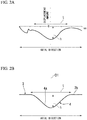
Fig. 2A is a view showing a 2D shape measurement result (an axial direction of a pivot position) of an inner circumferential surface (a concave portion) of the tilting pad. -
Fig. 2B is a cross-sectional view showing an example of an inner circumferential surface (a concave portion) of the tilting pad of the tilting pad journal bearing according to an embodiment of the present invention. -
Fig. 3A is a perspective view showing a pivot of the tilting pad journal bearing according to an embodiment of the present invention. -
Fig. 3B is a perspective view showing the pivot of the tilting pad journal bearing according to an embodiment of the present invention. -
Fig. 4 is a flowchart showing an example of a tilting pad journal bearing manufacturing method according to an embodiment of the present invention. -
Fig. 5 is a view showing a process of pressure-welding a resin material against the inner circumferential surface of the tilting pad in the tilting pad journal bearing manufacturing method according to an embodiment of the present invention. - Hereinafter, a tilting pad journal bearing manufacturing method, a tilting pad journal bearing, and a compressor according to an embodiment of the present invention will be described referring to
Figs. 1 to 5 . - In this embodiment, description will be provided on the assumption that the tilting pad journal bearing according to the present invention is a dynamic pressure gas bearing. The dynamic pressure gas bearing compresses a gas between the inner circumferential surfaces of each tilting pad (bearing pad) and the outer circumferential surface of the rotary shaft and generates a dynamic pressure, using gas rather than oil or water as a lubricant. That is, the dynamic pressure gas bearing rotatably supports a rotary shaft that rotates at a high speed, by forming a gas film (a lubricating film) between the inner circumferential surfaces of each tilting pad and the outer circumferential surface of the rotary shaft.
- The compressor of this embodiment is, for example, a turbo compressor or the like, and is configured to rotate the rotary shaft at high speed around the axis and compress the fluid by utilizing the rotation of the rotary shaft. For example, an impeller is rotated by the rotary shaft, and the gas is compressed by the centrifugal force of the rotating impeller.
- The compressor includes a tilting pad journal bearing as means for rotatably supporting the rotary shaft.
- As shown in
Fig. 1 , a tilting pad journal bearing A of the present embodiment includes a bearing housing (not shown), a plurality ofpivots 1, and a plurality oftilting pads 2. The bearing housing (not shown) is formed in a substantially cylindrical shape. A rotary shaft (not shown) is inserted into the bearing housing (not shown). The axes of the bearing housing (not shown) and the rotary shaft (not shown) are disposed coaxially with each other. - The plurality of
pivots 1 are integrally attached to the bearing housing (not shown). - Each of the plurality of
tilting pads 2 is formed in a circular arc-shaped plate shape when viewed from an axial direction. Thetilting pads 2 are attached to adistal end portions 1a of thepivot 1, respectively. Thetilting pads 2 are arranged in a substantially ring shape to surround the rotary shaft (not shown) in the bearing housing (not shown). - The
tilting pad 2 of this embodiment is provided with a pivotfitting hole 3. The pivotfitting hole 3 is recessed from the outercircumferential surface 2a of thetilting pad 2 toward the innercircumferential surface 2b side. The pivotfitting hole 3 is formed to have a diameter smaller than an outer diameter of thedistal end portion 1a of thepivot 1 which is formed in a substantially columnar shape. Thedistal end portion 1a of thepivot 1 is attached to each pivotfitting hole 3 of eachtilting pad 2 by "interference fitting" such as a shrinkage-fitting, a cold-fitting, and a press-fitting. That is, thetilting pad 2 is integrally fixed to thepivot 1 and is supported by thepivot 1. - As shown in
Fig. 2B , eachtilting pad 2 has a concave portion 4 formed on a concave curved innercircumferential surface 2b. The concave portion 4 has a substantially concavecurved surface 4a with an extension line of an axis O1 of thepivot 1 as a substantial center. - As shown in
Figs. 3A and 3B , thepivot 1 of this embodiment is formed in a substantially columnar shape, and has a compressedgas supply path 5 formed to penetrate from arear end portion 1b side to thedistal end portion 1a (distal end surface). The compressedgas supply path 5 is intended to supply the compressed gas between the innercircumferential surfaces 2b of eachtilting pad 2 and the outer circumferential surface (not shown) of the rotary shaft before starting to rotate the rotary shaft. By forming a gas film between the innercircumferential surface 2b of thetilting pad 2 and the outer circumferential surface (not shown) of the rotary shaft, it is possible to bring thetilting pad 2 and the rotary shaft into a non-contact state. - Next, a method for manufacturing the tilting pad journal bearing A in the present embodiment will be described with reference to
Fig. 4 . In order to manufacture the tilting pad journal bearing A of the present embodiment having the above-described configuration, metal material is first machined to roughly process aback metal portion 2c (seeFig. 5 ) of the tilting pad 2 (step S01). - Next, a
resin material 6 such as polyether ether ketone resin (PEEK) is affixed by laminating to an inner circumferential surface 2d (seeFig. 5 ) of theback metal portion 2c of thetilting pad 2 formed into a concave circular arc surface shape having a predetermined curvature by rough processing. Further, theresin material 6 is pressure-welded by the metal mold 7, and theresin material 6 is integrated with the inner circumferential surface portion of the tilting pad 2 (step S02). - Next, the
back metal portion 2c of thetilting pad 2 is machined to form a convex circular arc-shaped outercircumferential surface 2a having a predetermined curvature as shown inFig. 1 . Further, a pivotfitting hole 3 is formed at a predetermined position on the outercircumferential surface 2a (a first process). When forming the pivotfitting hole 3, its inner diameter is made slightly smaller than the outer diameter of thedistal end portion 1a of the substantiallycolumnar pivot 1. For example, in the present embodiment, the pivotfitting hole 3 is formed to have a diameter smaller than the outer diameter of thepivot 1 by about 100 µm. Further, as described above, the tilting pad 2 (theback metal portion 2c) formed into a circular arc shape having a predetermined shape is finished (step S03). - Next, the
distal end portion 1a of the substantiallycolumnar pivot 1 is attached to the pivotfitting hole 3 of thetilting pad 2 by "interference-fitting" such as shrink-fitting, cold-fitting, or press-fitting (a second process). As a result, thepivot 1 is set to a state of being integrally attached to thetilting pad 2. - At this time, by attaching the
distal end portion 1a of thepivot 1 to the pivotfitting hole 3 with "interference-fitting", as shown inFigs. 2A and 2B , an interference-fitting is performed, and at the same time, a concave portion 4 is automatically formed on the concave curved innercircumferential surface 2b of thetilting pad 2. When the "interference-fitting" is performed, a force drawn toward the outercircumferential surface 2a, that is, the inner side inevitably occurs with respect to the concave curved innercircumferential surface 2b of thetilting pad 2. The concave portion 4 is automatically formed on the innercircumferential surface 2b by this force. - For example, when the
pivot 1 having an outer diameter of thedistal end portion 1a of 50 mm is "interference-fitted" into the pivotfitting hole 3 having a smaller diameter than the outer diameter of thedistal end portion 1a of thepivot 1 by about 100 µm, the concave portion 4 having a concavecurved surface 4a having a maximum depth h of about 15 µm and an inner diameter t of about 100 mm is automatically formed with the extension line of the axis O1 of thepivot 1 substantially at the center. - According to the tilting pad journal bearing A of the present embodiment, since the concave portion 4 is formed on the concave curved inner
circumferential surface 2b of thetilting pad 2, it is possible to induce the flow of the gas as the lubricant toward the concave portion 4, and the flow of the lubricant around the concave portion 4. Therefore, it is possible to suppress the local temperature rise of the central portion of thetilting pad 2 and the local pressure rise of the lubricating film. - This makes it possible to suppress occurrence of the local deformation in the
tilting pad 2. As a result, it is possible to improve bearing performance (load capacity). - An embodiment of the method for manufacturing the tilting pad journal bearing, the tilting pad journal bearing, and the compressor according to the present invention have been described above. However, the present invention is not limited to the above-described embodiment and can be appropriately changed within the scope that does not depart from the spirit of the invention.
- For example, in the present embodiment, the tilting pad journal bearing A according to the present invention is provided in a compressor such as a turbo compressor. However, the tilting pad journal bearing A according to the present invention can be applied to any bearing for suitably supporting a radial load and rotatably supporting a rotary shaft that rotates around an axis.
- The compressor of the present invention is provided with the tilting pad journal bearing A, may be configured to compress the fluid in accordance with the rotation of the rotary shaft around the axis, and may be, for example, a compressor other than a turbo compressor, such as a rotary compressor and a scroll compressor.
- In the present embodiment, the tilting pad journal bearing A according to the present invention has been described as a dynamic pressure gas bearing that uses gas, rather than oil or water, as a lubricant. However, the tilting pad journal bearing A according to the present invention may rotatably support the rotary shaft, using a lubricant such as oil or water other than a gas. In this case, it is also possible to obtain the same operation and effects as the present embodiment.
- The present invention can be applied to a tilting pad journal bearing and a compressor. According to the present invention, since it is possible to suppress occurrence of local deformation in the tilting pad, the bearing performance (load capability) can be improved.
-
- 1 Pivot
- 1a Distal end portion
- 1b Rear end portion
- 2 Tilting pad (bearing pad)
- 2a Outer circumferential surface
- 2b Inner circumferential surface
- 2c Back metal portion
- 2d Inner circumferential surface of back metal portion
- 3 Pivot fitting hole
- 4 Concave portion
- 4a Concave curved surface
- 5 Compressed gas supply path
- 6 Resin material
- 7 Metal old
- O1 Axis of pivot
Claims (5)
- A method for manufacturing a tilting pad journal bearing including a bearing housing formed in a tubular shape and having a rotary shaft inserted therein, a plurality of pivots integrally attached to the bearing housing, and a plurality of tilting pads attached to a distal end portion of the pivot and disposed to surround the rotary shaft inside the bearing housing, the method comprising:a first process of forming a pivot fitting hole on a convex curved outer circumferential surface of the tilting pad, the pivot fitting hole being recessed from the outer circumferential surface toward an inner circumferential surface side and having an inner diameter smaller than an outer diameter of the distal end portion of the pivot; anda second process of forming a concave portion on the concave curved inner circumferential surface of the tilting pad by attaching the distal end portion of the pivot to the pivot fitting hole by interference-fitting.
- The method for manufacturing the tilting pad journal bearing according to claim 1, wherein
the tilting pad journal bearing is a dynamic gas bearing which compresses gas between the inner circumferential surface of the tilting pad and an outer circumferential surface of the rotary shaft to generate a dynamic pressure and forms a gas film between the inner circumferential surface of the tilting pad and the outer circumferential surface of the rotary shaft to rotatably support the rotary shaft in a non-contact state. - A tilting pad journal bearing comprising
a bearing housing formed in a tubular shape and having a rotary shaft inserted therein,
a plurality of pivots integrally attached to the bearing housing, and
a plurality of tilting pads attached to a distal end portion of the pivot and disposed in a substantially ring shape to surround the rotary shaft inside the bearing housing,
wherein a concave portion substantially centered on an extension line of an axis of the pivot is provided on a concave curved inner circumferential surface of the tilting pad. - The tilting pad journal bearing according to claim 3, wherein
the tilting pad journal bearing is a dynamic gas bearing which compresses gas between the inner circumferential surface of the tilting pad and an outer circumferential surface of the rotary shaft to generate a dynamic pressure and forms a gas film between the inner circumferential surface of the tilting pad and the outer circumferential surface of the rotary shaft to rotatably support the rotary shaft in a non-contact state. - A compressor comprising
the tilting pad journal bearing according to claim 3 or 4 and configured to compress a fluid in accordance with rotation about the axis of the rotary shaft.
Applications Claiming Priority (2)
| Application Number | Priority Date | Filing Date | Title |
|---|---|---|---|
| JP2016242569A JP6853660B2 (en) | 2016-12-14 | 2016-12-14 | Manufacturing method of tilting pad journal bearing |
| PCT/JP2017/024478 WO2018109965A1 (en) | 2016-12-14 | 2017-07-04 | Tilting pad journal bearing manufacturing method, tilting pad journal bearing, and compressor |
Publications (3)
| Publication Number | Publication Date |
|---|---|
| EP3473875A1 true EP3473875A1 (en) | 2019-04-24 |
| EP3473875A4 EP3473875A4 (en) | 2019-08-28 |
| EP3473875B1 EP3473875B1 (en) | 2020-09-02 |
Family
ID=62558366
Family Applications (1)
| Application Number | Title | Priority Date | Filing Date |
|---|---|---|---|
| EP17879678.5A Active EP3473875B1 (en) | 2016-12-14 | 2017-07-04 | Tilting pad journal bearing manufacturing method, tilting pad journal bearing, and compressor |
Country Status (4)
| Country | Link |
|---|---|
| US (1) | US10801544B2 (en) |
| EP (1) | EP3473875B1 (en) |
| JP (1) | JP6853660B2 (en) |
| WO (1) | WO2018109965A1 (en) |
Families Citing this family (1)
| Publication number | Priority date | Publication date | Assignee | Title |
|---|---|---|---|---|
| DE102016106005B4 (en) * | 2016-04-01 | 2019-12-24 | Zollern Bhw Gleitlager Gmbh & Co. Kg | tilting pad |
Family Cites Families (19)
| Publication number | Priority date | Publication date | Assignee | Title |
|---|---|---|---|---|
| US2167882A (en) * | 1935-09-16 | 1939-08-01 | Gustave Fast Engineering Corp | Block bearing |
| FR1353661A (en) * | 1963-01-19 | 1964-02-28 | Rateau Soc | Improvement in gas bearings |
| JPS58420B2 (en) | 1978-06-23 | 1983-01-06 | 武田薬品工業株式会社 | Imidazolone carboxamide derivatives and their production method |
| CH668811A5 (en) * | 1984-07-19 | 1989-01-31 | Glyco Metall Werke | HYDRODYNAMIC SLIDING BEARING. |
| JPS62127508A (en) * | 1985-11-29 | 1987-06-09 | Hitachi Ltd | Tailing pad journal bearing |
| JPH03121306A (en) | 1989-10-02 | 1991-05-23 | Toshiba Corp | Tilting pad shaped dynamic pressure gas bearing |
| JPH07317752A (en) * | 1994-05-30 | 1995-12-08 | Mitsubishi Heavy Ind Ltd | Dynamical pressure gas bearing |
| JP3377612B2 (en) * | 1994-07-27 | 2003-02-17 | 三菱重工業株式会社 | Dynamic pressure gas journal bearing |
| GB2294511A (en) * | 1994-10-26 | 1996-05-01 | Welsh Innovations Ltd | Tilting pad journal bearing |
| CN2352752Y (en) * | 1998-09-03 | 1999-12-08 | 东方汽轮机厂 | Asymmetry tiltably-supprted segments bearing |
| JP2000266040A (en) * | 1999-03-16 | 2000-09-26 | Eagle Ind Co Ltd | Slide bearing |
| JP2001124062A (en) * | 1999-10-21 | 2001-05-08 | Hitachi Ltd | Tilting pad bearing device |
| US7066651B2 (en) * | 2004-07-09 | 2006-06-27 | Rotating Machinery Technology Inc | Disc spring centering device for squeeze film dampers |
| US7758247B2 (en) * | 2005-02-28 | 2010-07-20 | Kingsbury, Inc. | Journal bearing having surface-contact retained shoes |
| US7625121B2 (en) * | 2005-09-28 | 2009-12-01 | Elliott Company | Bearing assembly and centering support structure therefor |
| JP5800420B2 (en) * | 2011-09-07 | 2015-10-28 | 三菱日立パワーシステムズ株式会社 | Journal bearing |
| JP2015010672A (en) * | 2013-06-28 | 2015-01-19 | 株式会社日立製作所 | Tilting pad type journal bearing |
| CN205298262U (en) * | 2015-12-18 | 2016-06-08 | 中车集团台州第七八一六工厂 | A tilting pad bearing for rotor |
| JP6709061B2 (en) | 2016-02-04 | 2020-06-10 | 三菱重工コンプレッサ株式会社 | Tilting pad gas bearing |
-
2016
- 2016-12-14 JP JP2016242569A patent/JP6853660B2/en active Active
-
2017
- 2017-07-04 US US16/319,370 patent/US10801544B2/en active Active
- 2017-07-04 WO PCT/JP2017/024478 patent/WO2018109965A1/en not_active Ceased
- 2017-07-04 EP EP17879678.5A patent/EP3473875B1/en active Active
Also Published As
| Publication number | Publication date |
|---|---|
| EP3473875A4 (en) | 2019-08-28 |
| JP6853660B2 (en) | 2021-03-31 |
| WO2018109965A1 (en) | 2018-06-21 |
| JP2018096479A (en) | 2018-06-21 |
| EP3473875B1 (en) | 2020-09-02 |
| US10801544B2 (en) | 2020-10-13 |
| US20190226519A1 (en) | 2019-07-25 |
Similar Documents
| Publication | Publication Date | Title |
|---|---|---|
| US10808757B2 (en) | Air bearing and rotor system | |
| JP6678377B2 (en) | Auxiliary bearings for magnetically suspended rotor systems | |
| TW507050B (en) | Thrust bearing arrangement | |
| JP2004003582A (en) | Dynamic-pressure bearing device | |
| CN106662143A (en) | Fluid dynamic bearing device, and bearing member and shaft member for use in same | |
| KR20190027518A (en) | Air foil bearing and air compressor having the same | |
| CN109563879B (en) | Ball bearing, spindle device, and machine tool | |
| EP3473875B1 (en) | Tilting pad journal bearing manufacturing method, tilting pad journal bearing, and compressor | |
| US11976665B2 (en) | Compressor | |
| JP2001107964A (en) | Fluid bearing | |
| CN113811695A (en) | Turbochargers or hydrodynamic plain bearings with hydrodynamic plain bearings | |
| CN104169597B (en) | Sliding thrust bearing | |
| WO2019087890A1 (en) | Tilting pad bearing | |
| US11280349B2 (en) | Impeller and rotary machine | |
| JP4529129B2 (en) | Hydrostatic air bearing spindle | |
| CN113614395B (en) | Fluid dynamic bearing device | |
| WO2012144288A1 (en) | Fluid dynamic pressure bearing device | |
| CN107869512B (en) | Shaft member for fluid bearing device, method for manufacturing same, and fluid bearing device | |
| CN100392950C (en) | electric motor | |
| JP2020176673A (en) | Seal structure and seal | |
| JP2004340385A (en) | Dynamic pressure type bearing unit | |
| KR102177353B1 (en) | Supercharger | |
| JP2016118229A (en) | Sliding bearing structure, and method of manufacturing bearing in the sliding bearing | |
| JP2013057335A (en) | Journal bearing | |
| JP2002021843A (en) | Thrust bearing device |
Legal Events
| Date | Code | Title | Description |
|---|---|---|---|
| STAA | Information on the status of an ep patent application or granted ep patent |
Free format text: STATUS: THE INTERNATIONAL PUBLICATION HAS BEEN MADE |
|
| PUAI | Public reference made under article 153(3) epc to a published international application that has entered the european phase |
Free format text: ORIGINAL CODE: 0009012 |
|
| STAA | Information on the status of an ep patent application or granted ep patent |
Free format text: STATUS: REQUEST FOR EXAMINATION WAS MADE |
|
| 17P | Request for examination filed |
Effective date: 20190118 |
|
| AK | Designated contracting states |
Kind code of ref document: A1 Designated state(s): AL AT BE BG CH CY CZ DE DK EE ES FI FR GB GR HR HU IE IS IT LI LT LU LV MC MK MT NL NO PL PT RO RS SE SI SK SM TR |
|
| AX | Request for extension of the european patent |
Extension state: BA ME |
|
| A4 | Supplementary search report drawn up and despatched |
Effective date: 20190725 |
|
| RIC1 | Information provided on ipc code assigned before grant |
Ipc: F16C 33/20 20060101ALI20190719BHEP Ipc: F16C 32/06 20060101ALI20190719BHEP Ipc: F16C 43/02 20060101ALI20190719BHEP Ipc: F02C 7/06 20060101ALI20190719BHEP Ipc: F16C 17/03 20060101AFI20190719BHEP |
|
| REG | Reference to a national code |
Ref country code: DE Ref legal event code: R079 Ref document number: 602017023066 Country of ref document: DE Free format text: PREVIOUS MAIN CLASS: F16C0017030000 Ipc: F01D0025220000 |
|
| DAV | Request for validation of the european patent (deleted) | ||
| DAX | Request for extension of the european patent (deleted) | ||
| GRAP | Despatch of communication of intention to grant a patent |
Free format text: ORIGINAL CODE: EPIDOSNIGR1 |
|
| STAA | Information on the status of an ep patent application or granted ep patent |
Free format text: STATUS: GRANT OF PATENT IS INTENDED |
|
| RIC1 | Information provided on ipc code assigned before grant |
Ipc: F16C 32/06 20060101ALI20200311BHEP Ipc: F04D 29/057 20060101ALI20200311BHEP Ipc: F16C 17/03 20060101ALI20200311BHEP Ipc: F16C 33/20 20060101ALI20200311BHEP Ipc: F01D 25/22 20060101AFI20200311BHEP Ipc: F16C 43/02 20060101ALI20200311BHEP Ipc: F02C 7/06 20060101ALI20200311BHEP |
|
| INTG | Intention to grant announced |
Effective date: 20200327 |
|
| GRAS | Grant fee paid |
Free format text: ORIGINAL CODE: EPIDOSNIGR3 |
|
| GRAA | (expected) grant |
Free format text: ORIGINAL CODE: 0009210 |
|
| STAA | Information on the status of an ep patent application or granted ep patent |
Free format text: STATUS: THE PATENT HAS BEEN GRANTED |
|
| AK | Designated contracting states |
Kind code of ref document: B1 Designated state(s): AL AT BE BG CH CY CZ DE DK EE ES FI FR GB GR HR HU IE IS IT LI LT LU LV MC MK MT NL NO PL PT RO RS SE SI SK SM TR |
|
| REG | Reference to a national code |
Ref country code: GB Ref legal event code: FG4D |
|
| REG | Reference to a national code |
Ref country code: AT Ref legal event code: REF Ref document number: 1309035 Country of ref document: AT Kind code of ref document: T Effective date: 20200915 Ref country code: CH Ref legal event code: EP |
|
| REG | Reference to a national code |
Ref country code: DE Ref legal event code: R096 Ref document number: 602017023066 Country of ref document: DE |
|
| REG | Reference to a national code |
Ref country code: IE Ref legal event code: FG4D |
|
| REG | Reference to a national code |
Ref country code: LT Ref legal event code: MG4D |
|
| PG25 | Lapsed in a contracting state [announced via postgrant information from national office to epo] |
Ref country code: LT Free format text: LAPSE BECAUSE OF FAILURE TO SUBMIT A TRANSLATION OF THE DESCRIPTION OR TO PAY THE FEE WITHIN THE PRESCRIBED TIME-LIMIT Effective date: 20200902 Ref country code: HR Free format text: LAPSE BECAUSE OF FAILURE TO SUBMIT A TRANSLATION OF THE DESCRIPTION OR TO PAY THE FEE WITHIN THE PRESCRIBED TIME-LIMIT Effective date: 20200902 Ref country code: SE Free format text: LAPSE BECAUSE OF FAILURE TO SUBMIT A TRANSLATION OF THE DESCRIPTION OR TO PAY THE FEE WITHIN THE PRESCRIBED TIME-LIMIT Effective date: 20200902 Ref country code: GR Free format text: LAPSE BECAUSE OF FAILURE TO SUBMIT A TRANSLATION OF THE DESCRIPTION OR TO PAY THE FEE WITHIN THE PRESCRIBED TIME-LIMIT Effective date: 20201203 Ref country code: NO Free format text: LAPSE BECAUSE OF FAILURE TO SUBMIT A TRANSLATION OF THE DESCRIPTION OR TO PAY THE FEE WITHIN THE PRESCRIBED TIME-LIMIT Effective date: 20201202 Ref country code: FI Free format text: LAPSE BECAUSE OF FAILURE TO SUBMIT A TRANSLATION OF THE DESCRIPTION OR TO PAY THE FEE WITHIN THE PRESCRIBED TIME-LIMIT Effective date: 20200902 Ref country code: BG Free format text: LAPSE BECAUSE OF FAILURE TO SUBMIT A TRANSLATION OF THE DESCRIPTION OR TO PAY THE FEE WITHIN THE PRESCRIBED TIME-LIMIT Effective date: 20201202 |
|
| REG | Reference to a national code |
Ref country code: NL Ref legal event code: MP Effective date: 20200902 |
|
| REG | Reference to a national code |
Ref country code: AT Ref legal event code: MK05 Ref document number: 1309035 Country of ref document: AT Kind code of ref document: T Effective date: 20200902 |
|
| PG25 | Lapsed in a contracting state [announced via postgrant information from national office to epo] |
Ref country code: RS Free format text: LAPSE BECAUSE OF FAILURE TO SUBMIT A TRANSLATION OF THE DESCRIPTION OR TO PAY THE FEE WITHIN THE PRESCRIBED TIME-LIMIT Effective date: 20200902 Ref country code: LV Free format text: LAPSE BECAUSE OF FAILURE TO SUBMIT A TRANSLATION OF THE DESCRIPTION OR TO PAY THE FEE WITHIN THE PRESCRIBED TIME-LIMIT Effective date: 20200902 Ref country code: PL Free format text: LAPSE BECAUSE OF FAILURE TO SUBMIT A TRANSLATION OF THE DESCRIPTION OR TO PAY THE FEE WITHIN THE PRESCRIBED TIME-LIMIT Effective date: 20200902 |
|
| PG25 | Lapsed in a contracting state [announced via postgrant information from national office to epo] |
Ref country code: SM Free format text: LAPSE BECAUSE OF FAILURE TO SUBMIT A TRANSLATION OF THE DESCRIPTION OR TO PAY THE FEE WITHIN THE PRESCRIBED TIME-LIMIT Effective date: 20200902 Ref country code: CZ Free format text: LAPSE BECAUSE OF FAILURE TO SUBMIT A TRANSLATION OF THE DESCRIPTION OR TO PAY THE FEE WITHIN THE PRESCRIBED TIME-LIMIT Effective date: 20200902 Ref country code: PT Free format text: LAPSE BECAUSE OF FAILURE TO SUBMIT A TRANSLATION OF THE DESCRIPTION OR TO PAY THE FEE WITHIN THE PRESCRIBED TIME-LIMIT Effective date: 20210104 Ref country code: RO Free format text: LAPSE BECAUSE OF FAILURE TO SUBMIT A TRANSLATION OF THE DESCRIPTION OR TO PAY THE FEE WITHIN THE PRESCRIBED TIME-LIMIT Effective date: 20200902 Ref country code: EE Free format text: LAPSE BECAUSE OF FAILURE TO SUBMIT A TRANSLATION OF THE DESCRIPTION OR TO PAY THE FEE WITHIN THE PRESCRIBED TIME-LIMIT Effective date: 20200902 |
|
| PG25 | Lapsed in a contracting state [announced via postgrant information from national office to epo] |
Ref country code: IS Free format text: LAPSE BECAUSE OF FAILURE TO SUBMIT A TRANSLATION OF THE DESCRIPTION OR TO PAY THE FEE WITHIN THE PRESCRIBED TIME-LIMIT Effective date: 20210102 Ref country code: AL Free format text: LAPSE BECAUSE OF FAILURE TO SUBMIT A TRANSLATION OF THE DESCRIPTION OR TO PAY THE FEE WITHIN THE PRESCRIBED TIME-LIMIT Effective date: 20200902 Ref country code: AT Free format text: LAPSE BECAUSE OF FAILURE TO SUBMIT A TRANSLATION OF THE DESCRIPTION OR TO PAY THE FEE WITHIN THE PRESCRIBED TIME-LIMIT Effective date: 20200902 Ref country code: ES Free format text: LAPSE BECAUSE OF FAILURE TO SUBMIT A TRANSLATION OF THE DESCRIPTION OR TO PAY THE FEE WITHIN THE PRESCRIBED TIME-LIMIT Effective date: 20200902 |
|
| REG | Reference to a national code |
Ref country code: DE Ref legal event code: R097 Ref document number: 602017023066 Country of ref document: DE |
|
| PG25 | Lapsed in a contracting state [announced via postgrant information from national office to epo] |
Ref country code: SK Free format text: LAPSE BECAUSE OF FAILURE TO SUBMIT A TRANSLATION OF THE DESCRIPTION OR TO PAY THE FEE WITHIN THE PRESCRIBED TIME-LIMIT Effective date: 20200902 |
|
| PLBE | No opposition filed within time limit |
Free format text: ORIGINAL CODE: 0009261 |
|
| STAA | Information on the status of an ep patent application or granted ep patent |
Free format text: STATUS: NO OPPOSITION FILED WITHIN TIME LIMIT |
|
| 26N | No opposition filed |
Effective date: 20210603 |
|
| PG25 | Lapsed in a contracting state [announced via postgrant information from national office to epo] |
Ref country code: DK Free format text: LAPSE BECAUSE OF FAILURE TO SUBMIT A TRANSLATION OF THE DESCRIPTION OR TO PAY THE FEE WITHIN THE PRESCRIBED TIME-LIMIT Effective date: 20200902 Ref country code: SI Free format text: LAPSE BECAUSE OF FAILURE TO SUBMIT A TRANSLATION OF THE DESCRIPTION OR TO PAY THE FEE WITHIN THE PRESCRIBED TIME-LIMIT Effective date: 20200902 |
|
| REG | Reference to a national code |
Ref country code: CH Ref legal event code: PL |
|
| GBPC | Gb: european patent ceased through non-payment of renewal fee |
Effective date: 20210704 |
|
| PG25 | Lapsed in a contracting state [announced via postgrant information from national office to epo] |
Ref country code: MC Free format text: LAPSE BECAUSE OF FAILURE TO SUBMIT A TRANSLATION OF THE DESCRIPTION OR TO PAY THE FEE WITHIN THE PRESCRIBED TIME-LIMIT Effective date: 20200902 |
|
| REG | Reference to a national code |
Ref country code: BE Ref legal event code: MM Effective date: 20210731 |
|
| PG25 | Lapsed in a contracting state [announced via postgrant information from national office to epo] |
Ref country code: LI Free format text: LAPSE BECAUSE OF NON-PAYMENT OF DUE FEES Effective date: 20210731 Ref country code: GB Free format text: LAPSE BECAUSE OF NON-PAYMENT OF DUE FEES Effective date: 20210704 Ref country code: CH Free format text: LAPSE BECAUSE OF NON-PAYMENT OF DUE FEES Effective date: 20210731 |
|
| PG25 | Lapsed in a contracting state [announced via postgrant information from national office to epo] |
Ref country code: LU Free format text: LAPSE BECAUSE OF NON-PAYMENT OF DUE FEES Effective date: 20210704 Ref country code: FR Free format text: LAPSE BECAUSE OF NON-PAYMENT OF DUE FEES Effective date: 20210731 |
|
| PG25 | Lapsed in a contracting state [announced via postgrant information from national office to epo] |
Ref country code: IE Free format text: LAPSE BECAUSE OF NON-PAYMENT OF DUE FEES Effective date: 20210704 Ref country code: BE Free format text: LAPSE BECAUSE OF NON-PAYMENT OF DUE FEES Effective date: 20210731 |
|
| PG25 | Lapsed in a contracting state [announced via postgrant information from national office to epo] |
Ref country code: NL Free format text: LAPSE BECAUSE OF NON-PAYMENT OF DUE FEES Effective date: 20200923 Ref country code: CY Free format text: LAPSE BECAUSE OF FAILURE TO SUBMIT A TRANSLATION OF THE DESCRIPTION OR TO PAY THE FEE WITHIN THE PRESCRIBED TIME-LIMIT Effective date: 20200902 |
|
| PG25 | Lapsed in a contracting state [announced via postgrant information from national office to epo] |
Ref country code: HU Free format text: LAPSE BECAUSE OF FAILURE TO SUBMIT A TRANSLATION OF THE DESCRIPTION OR TO PAY THE FEE WITHIN THE PRESCRIBED TIME-LIMIT; INVALID AB INITIO Effective date: 20170704 |
|
| PG25 | Lapsed in a contracting state [announced via postgrant information from national office to epo] |
Ref country code: MK Free format text: LAPSE BECAUSE OF FAILURE TO SUBMIT A TRANSLATION OF THE DESCRIPTION OR TO PAY THE FEE WITHIN THE PRESCRIBED TIME-LIMIT Effective date: 20200902 |
|
| PG25 | Lapsed in a contracting state [announced via postgrant information from national office to epo] |
Ref country code: TR Free format text: LAPSE BECAUSE OF FAILURE TO SUBMIT A TRANSLATION OF THE DESCRIPTION OR TO PAY THE FEE WITHIN THE PRESCRIBED TIME-LIMIT Effective date: 20200902 |
|
| PG25 | Lapsed in a contracting state [announced via postgrant information from national office to epo] |
Ref country code: MT Free format text: LAPSE BECAUSE OF FAILURE TO SUBMIT A TRANSLATION OF THE DESCRIPTION OR TO PAY THE FEE WITHIN THE PRESCRIBED TIME-LIMIT Effective date: 20200902 |
|
| PGFP | Annual fee paid to national office [announced via postgrant information from national office to epo] |
Ref country code: IT Payment date: 20240612 Year of fee payment: 8 |
|
| PGFP | Annual fee paid to national office [announced via postgrant information from national office to epo] |
Ref country code: DE Payment date: 20240529 Year of fee payment: 8 |
|
| REG | Reference to a national code |
Ref country code: DE Ref legal event code: R119 Ref document number: 602017023066 Country of ref document: DE |
|
| PG25 | Lapsed in a contracting state [announced via postgrant information from national office to epo] |
Ref country code: DE Free format text: LAPSE BECAUSE OF NON-PAYMENT OF DUE FEES Effective date: 20260203 |