EP3473862A1 - Multi-piece compressor housing for a turbocharger - Google Patents
Multi-piece compressor housing for a turbocharger Download PDFInfo
- Publication number
- EP3473862A1 EP3473862A1 EP18200282.4A EP18200282A EP3473862A1 EP 3473862 A1 EP3473862 A1 EP 3473862A1 EP 18200282 A EP18200282 A EP 18200282A EP 3473862 A1 EP3473862 A1 EP 3473862A1
- Authority
- EP
- European Patent Office
- Prior art keywords
- housing structure
- volute
- tubular portion
- radial portion
- compressor housing
- Prior art date
- Legal status (The legal status is an assumption and is not a legal conclusion. Google has not performed a legal analysis and makes no representation as to the accuracy of the status listed.)
- Granted
Links
Images



Classifications
-
- F—MECHANICAL ENGINEERING; LIGHTING; HEATING; WEAPONS; BLASTING
- F01—MACHINES OR ENGINES IN GENERAL; ENGINE PLANTS IN GENERAL; STEAM ENGINES
- F01D—NON-POSITIVE DISPLACEMENT MACHINES OR ENGINES, e.g. STEAM TURBINES
- F01D25/00—Component parts, details, or accessories, not provided for in, or of interest apart from, other groups
- F01D25/24—Casings; Casing parts, e.g. diaphragms, casing fastenings
- F01D25/26—Double casings; Measures against temperature strain in casings
-
- F—MECHANICAL ENGINEERING; LIGHTING; HEATING; WEAPONS; BLASTING
- F04—POSITIVE - DISPLACEMENT MACHINES FOR LIQUIDS; PUMPS FOR LIQUIDS OR ELASTIC FLUIDS
- F04D—NON-POSITIVE-DISPLACEMENT PUMPS
- F04D29/00—Details, component parts, or accessories
- F04D29/40—Casings; Connections of working fluid
- F04D29/42—Casings; Connections of working fluid for radial or helico-centrifugal pumps
- F04D29/4206—Casings; Connections of working fluid for radial or helico-centrifugal pumps especially adapted for elastic fluid pumps
-
- F—MECHANICAL ENGINEERING; LIGHTING; HEATING; WEAPONS; BLASTING
- F01—MACHINES OR ENGINES IN GENERAL; ENGINE PLANTS IN GENERAL; STEAM ENGINES
- F01D—NON-POSITIVE DISPLACEMENT MACHINES OR ENGINES, e.g. STEAM TURBINES
- F01D25/00—Component parts, details, or accessories, not provided for in, or of interest apart from, other groups
- F01D25/28—Supporting or mounting arrangements, e.g. for turbine casing
- F01D25/285—Temporary support structures, e.g. for testing, assembling, installing, repairing; Assembly methods using such structures
-
- F—MECHANICAL ENGINEERING; LIGHTING; HEATING; WEAPONS; BLASTING
- F04—POSITIVE - DISPLACEMENT MACHINES FOR LIQUIDS; PUMPS FOR LIQUIDS OR ELASTIC FLUIDS
- F04D—NON-POSITIVE-DISPLACEMENT PUMPS
- F04D27/00—Control, e.g. regulation, of pumps, pumping installations or pumping systems specially adapted for elastic fluids
- F04D27/009—Control, e.g. regulation, of pumps, pumping installations or pumping systems specially adapted for elastic fluids by bleeding, by passing or recycling fluid
-
- F—MECHANICAL ENGINEERING; LIGHTING; HEATING; WEAPONS; BLASTING
- F04—POSITIVE - DISPLACEMENT MACHINES FOR LIQUIDS; PUMPS FOR LIQUIDS OR ELASTIC FLUIDS
- F04D—NON-POSITIVE-DISPLACEMENT PUMPS
- F04D29/00—Details, component parts, or accessories
- F04D29/40—Casings; Connections of working fluid
- F04D29/42—Casings; Connections of working fluid for radial or helico-centrifugal pumps
- F04D29/4206—Casings; Connections of working fluid for radial or helico-centrifugal pumps especially adapted for elastic fluid pumps
- F04D29/4213—Casings; Connections of working fluid for radial or helico-centrifugal pumps especially adapted for elastic fluid pumps suction ports
-
- F—MECHANICAL ENGINEERING; LIGHTING; HEATING; WEAPONS; BLASTING
- F04—POSITIVE - DISPLACEMENT MACHINES FOR LIQUIDS; PUMPS FOR LIQUIDS OR ELASTIC FLUIDS
- F04D—NON-POSITIVE-DISPLACEMENT PUMPS
- F04D29/00—Details, component parts, or accessories
- F04D29/66—Combating cavitation, whirls, noise, vibration or the like; Balancing
- F04D29/661—Combating cavitation, whirls, noise, vibration or the like; Balancing especially adapted for elastic fluid pumps
- F04D29/663—Sound attenuation
-
- F—MECHANICAL ENGINEERING; LIGHTING; HEATING; WEAPONS; BLASTING
- F04—POSITIVE - DISPLACEMENT MACHINES FOR LIQUIDS; PUMPS FOR LIQUIDS OR ELASTIC FLUIDS
- F04D—NON-POSITIVE-DISPLACEMENT PUMPS
- F04D29/00—Details, component parts, or accessories
- F04D29/66—Combating cavitation, whirls, noise, vibration or the like; Balancing
- F04D29/68—Combating cavitation, whirls, noise, vibration or the like; Balancing by influencing boundary layers
- F04D29/681—Combating cavitation, whirls, noise, vibration or the like; Balancing by influencing boundary layers especially adapted for elastic fluid pumps
- F04D29/685—Inducing localised fluid recirculation in the stator-rotor interface
-
- F—MECHANICAL ENGINEERING; LIGHTING; HEATING; WEAPONS; BLASTING
- F04—POSITIVE - DISPLACEMENT MACHINES FOR LIQUIDS; PUMPS FOR LIQUIDS OR ELASTIC FLUIDS
- F04D—NON-POSITIVE-DISPLACEMENT PUMPS
- F04D25/00—Pumping installations or systems
- F04D25/02—Units comprising pumps and their driving means
- F04D25/04—Units comprising pumps and their driving means the pump being fluid-driven
-
- F—MECHANICAL ENGINEERING; LIGHTING; HEATING; WEAPONS; BLASTING
- F04—POSITIVE - DISPLACEMENT MACHINES FOR LIQUIDS; PUMPS FOR LIQUIDS OR ELASTIC FLUIDS
- F04D—NON-POSITIVE-DISPLACEMENT PUMPS
- F04D25/00—Pumping installations or systems
- F04D25/02—Units comprising pumps and their driving means
- F04D25/06—Units comprising pumps and their driving means the pump being electrically driven
-
- F—MECHANICAL ENGINEERING; LIGHTING; HEATING; WEAPONS; BLASTING
- F04—POSITIVE - DISPLACEMENT MACHINES FOR LIQUIDS; PUMPS FOR LIQUIDS OR ELASTIC FLUIDS
- F04D—NON-POSITIVE-DISPLACEMENT PUMPS
- F04D29/00—Details, component parts, or accessories
- F04D29/26—Rotors specially for elastic fluids
- F04D29/28—Rotors specially for elastic fluids for centrifugal or helico-centrifugal pumps for radial-flow or helico-centrifugal pumps
- F04D29/284—Rotors specially for elastic fluids for centrifugal or helico-centrifugal pumps for radial-flow or helico-centrifugal pumps for compressors
-
- F—MECHANICAL ENGINEERING; LIGHTING; HEATING; WEAPONS; BLASTING
- F05—INDEXING SCHEMES RELATING TO ENGINES OR PUMPS IN VARIOUS SUBCLASSES OF CLASSES F01-F04
- F05D—INDEXING SCHEME FOR ASPECTS RELATING TO NON-POSITIVE-DISPLACEMENT MACHINES OR ENGINES, GAS-TURBINES OR JET-PROPULSION PLANTS
- F05D2220/00—Application
- F05D2220/40—Application in turbochargers
-
- F—MECHANICAL ENGINEERING; LIGHTING; HEATING; WEAPONS; BLASTING
- F05—INDEXING SCHEMES RELATING TO ENGINES OR PUMPS IN VARIOUS SUBCLASSES OF CLASSES F01-F04
- F05D—INDEXING SCHEME FOR ASPECTS RELATING TO NON-POSITIVE-DISPLACEMENT MACHINES OR ENGINES, GAS-TURBINES OR JET-PROPULSION PLANTS
- F05D2260/00—Function
- F05D2260/96—Preventing, counteracting or reducing vibration or noise
- F05D2260/962—Preventing, counteracting or reducing vibration or noise by means of "anti-noise"
Definitions
- This disclosure relates to turbochargers, and more particularly, to a multi-piece compressor housing for a turbocharger to reduce manufacturing cost and increase quality.
- Turbochargers are forced-induction devices that are utilized to increase the pressure of the intake air provided to an engine.
- a compressor wheel is driven, for example by an electric motor, exhaust gas from the engine, or both, which pressurizes intake air for supply to the engine.
- pressurizing the intake air the engine may have increased power output compared to an otherwise comparable naturally aspirated engine.
- the compressor wheel is rotated within a compressor housing to draw ambient air in and expel compressed air out.
- the compressor housing generally includes a volute that functions as an outlet, an inlet extending axially from the volute, and a wheel cavity surrounded by the volute and in communication between the inlet and the volute. As the compressor wheel is rotated within the cavity, ambient air is drawn in axially through the inlet at an inducer end of the compressor wheel and expelled out radially through the volute at an exducer end of the compressor wheel.
- Compressor housings typically have a unitary construction in which a single component forms the volute and inlet.
- the complex shape of the volute usually requires that the compressor housing be fabricated using a sand casting technique and can require secondary machining (e.g., machining after the casting is complete), for example, to finish surfaces and form different features.
- secondary machining e.g., machining after the casting is complete
- a surface of an interior portion of the volute may be machined after the casting process in order to remove burs and/or other imperfections.
- residue such as sand particles, may accumulate on the compressor housing during the casting process. Removal of the residue from, for example, cavities of the compressor housing, may be difficult and time consuming.
- sand casting is a relatively slow process that prohibits the use of a reusable mold, which may increase the cost of the sand casting process and increase a potential for error during the sand casting process.
- multi-piece compressor housings for turbochargers and turbochargers includes such multi-piece compressor housings.
- a compressor housing for a turbocharger includes an outer housing structure, an inner housing structure, and a rear housing structure.
- the outer housing structure includes a first tubular portion and a first radial portion extending radially outward of the first tubular portion.
- the inner housing structure includes a second tubular portion and a second radial portion extending radially outward of the second tubular portion.
- the rear housing structure includes an inner radial portion and an outer radial portion extending radially outward of the inner radial portion.
- the outer housing structure, the inner housing structure, and the rear housing structure are formed separately from each other and are coupled to each other.
- a recirculation cavity is defined radially between the first tubular portion and the second tubular portion.
- a volute is cooperatively formed by the first radial portion and the outer radial portion.
- the first tubular portion and the second tubular portion cooperatively may form an inlet having an inlet opening and a tubular passage that communicate air to a wheel cavity.
- the volute may be cooperatively formed by the first radial portion, the second radial portion, and the outer radial portion.
- the first radial portion may form a forward portion of the volute
- the second radial portion may form an inner portion of the volute
- the outer radial portion may form a rearward portion of the volute.
- the outer housing structure may define a first recess that is cylindrical and in which the inner housing structure is received to form a seal therebetween and may define a second recess that is cylindrical in which the rear housing structure is received to form another seal therebetween.
- a compressor housing assembly for a turbocharger assembly includes an outer shell, an insert, and a rear housing structure.
- the outer shell includes an inlet portion having an outer circumferential surface and an inner circumferential surface that are concentric to one another.
- the insert includes an inlet portion having another outer circumferential surface and another inner circumferential surface that are concentric to one another.
- a slot extends through the other inner circumferential surface to the other outer circumferential surface.
- the rear housing structure is connected to the outer shell.
- a volute portion is defined by the rear housing structure and the outer shell.
- a recirculation cavity is defined by the outer shell and the insert. The slot forms an opening into the recirculation cavity.
- a turbocharger in a still further aspect, includes a drive source, a shaft, a compressor wheel, and a compressor wheel housing.
- the shaft is coupled to and rotated by the drive source.
- the compressor wheel is coupled to and rotated by the shaft.
- the compressor wheel housing includes an outer housing structure, an inner housing structure, and a rear housing structure.
- the outer housing structure includes a first tubular portion and a first radial portion extending radially outward of the first tubular portion.
- the inner housing structure includes a second tubular portion and a second radial portion extending radially outward of the second tubular portion.
- the rear housing structure includes an inner radial portion and an outer radial portion extending radially outward of the inner radial portion.
- the outer housing structure, the inner housing structure, and the rear housing structure are formed separately from each other and are coupled to each other.
- a recirculation cavity is defined radially between the first tubular portion and the second tubular portion.
- a volute is cooperatively formed by the first radial portion and the outer radial portion.
- a wheel cavity is cooperatively formed by the inner housing structure and the inner radial portion in which the compressor wheel is rotated.
- a compressor housing for a turbocharger which is formed of multiple components.
- the multiple components of the compressor housing may, for example, be manufactured with die casting and/or injection molding, which may provide faster cycle times and reuse of dies, as compared to sand casting.
- the multiple components may also be machined with higher quality (e.g., surface finish, finer detail, etc.) and/more easily than compressor housing having unitary construction (e.g., within the volute).
- a multi-piece or parted compressor housing of a turbocharger is provided.
- the multi-piece compressor housing may be adapted as a drop fit replacement for a compressor housing having a unitary construction.
- the multi-piece compressor housing may be adapted to connect to a turbocharger in the same or substantially the same way as a compressor housing having a unitary construction.
- the multi-piece compressor housing may provide improved performance (e.g., efficiency) from improved manufacturability due to the multi-piece configuration as compared to those having a unitary construction.
- the compressor housing includes various functional features, which may be formed individually or cooperatively by various structural components of the compressor housing.
- the functional features of the compressor housing include, for example, an inlet for receiving air, a wheel cavity in which the compressor wheel is rotated to compress the air, and a volute from which compressed air is expelled.
- Functional features of the compressor housing may also include a recirculating chamber and a noise attenuating feature.
- the structural components, which form the functional features of the compressor housing include an outer housing structure, an inner housing structure, and a rear housing structure.
- the inlet is formed by the outer housing structure and the inner housing structure
- the wheel cavity is formed by the inner housing structure and the rear housing structure
- the volute is formed by the outer housing structure, the inner housing structure, and the rear housing structure.
- the recirculation cavity may be formed by the outer housing structure and the inner housing structure.
- the noise attenuating feature may be formed by the outer housing structure.
- the structural components may be formed with reusable tools, such as a die or an injection mold.
- the structural components may further have open configurations, which provide access for subsequent machining (e.g., sanding, finishing, threading, etc.).
- Open configurations for example, include those configurations having surfaces that may face toward tooling for machining (e.g., facing toward or parallel with a plane and not away from such plane, such as by having no undercut surfaces).
- the compressor housing having multiple structural components may be manufactured with improved quality (e.g., surface finishing), reduced cost, and/or reduced time as compared to compressor housings that are functionally similar but have a unitary construction.
- FIG. 1 generally illustrates a perspective partial cross-section view of a turbocharger 100 for a compressor housing according to the principles of the present disclosure may be adapted to be used (e.g., the compressor housing 200 shown in FIGS. 2-6B ).
- the turbocharger 100 is an exhaust-gas driven forced induction device that is utilized in conjunction with an internal combustion engine (not shown).
- the turbocharger 100 includes a turbine wheel 110 that is in a turbine housing 120, which functions as a drive source.
- the turbine housing 120 includes an exhaust gas inlet 122 for receiving exhaust gas from the internal combustion engine. Exhaust gases are routed from the exhaust gas inlet 122 to the turbine wheel 110 before exiting the turbine housing 120 at an exhaust gas outlet 123.
- a wastegate 124 may be mounted in the turbine housing 120 to allow some or all the exhaust gas to bypass the turbine wheel 110.
- the wastegate 124 is movable between an open position and a closed position by an electric linear actuator 130.
- the turbocharger 100 may instead or additionally another drive source, such as an electric motor used alone or in conjunction with the turbine wheel.
- the turbocharger 100 includes a compressor wheel 140 located in a cavity of compressor housing 150.
- the compressor housing 150 includes an intake air inlet 152 and a volute 154 that forms an air outlet. Intake air is routed from the intake air inlet 152 to the compressor wheel 140, where the intake air is pressurized by rotation of the compressor wheel 140. The air then exits the compressor housing 150 through the volute 154 to be supplied to the internal combustion engine.
- Rotation of the compressor wheel 140 is driven by rotation of the turbine wheel 110.
- the turbine wheel 110 and the compressor wheel 140 are each connected to a shaft 160.
- the shaft 160 can be a substantially rigid member, and the turbine wheel 110 and the compressor wheel 140 can be connected to the shaft 160 in a manner that prevents rotation of the turbine wheel 110 and the compressor wheel 140 with respect to the shaft 160.
- the compressor wheel 140 can rotate in unison with the turbine wheel 110 in response to rotation of the turbine wheel 110.
- the shaft 160 is supported within a bearing housing 170 such that the shaft 160 may rotate freely with respect to the bearing housing 170 at a very high rotational speed.
- the bearing housing 170, the turbine housing 120, and the compressor housing 150 are arranged along an axis of rotation of the shaft 160.
- the bearing housing 170 is positioned between the turbine housing 120 and the compressor housing 150.
- the bearing housing 170 can incorporate lubrication and /or cooling features.
- the bearing housing 170 defines a cavity, which contains the shaft 160 and a thrust bearing 190.
- the cavity may be closed by an oil seal plate 180 (e.g., cover, closure, etc.).
- the shaft 160, the thrust bearing 190, and the oil seal plate 180 function to cooperatively transfer axial force (e.g., axial loading) from the turbine wheel 110 to the bearing housing 170 and, thereby, locate the shaft 160 axially relative to the bearing housing 170.
- a compressor housing 200 is generally illustrated.
- the compressor housing 200 may be adapted for use with the turbocharger 100 in place of the compressor housing 150.
- the compressor housing 200 forms an air inlet 212, a wheel cavity 216 in which the compressor wheel 140 rotates, and a volute 208 extending to an air outlet 214.
- the compressor housing 200 additionally includes a recirculation cavity 218 and a noise attenuation feature 220 (e.g., a noise attenuation device or "NAD").
- the air inlet 212 receives intake air in an axial direction.
- the wheel cavity 216 has a surface profile corresponding to the compressor wheel 140, receives air axially from the air inlet 212, and expels air radially to the volute 208.
- the volute 208 forms a cavity that extends circumferentially around the compressor wheel 140 and has a cross-sectional shape (e.g., circular) that gradually increases in size (e.g., diameter) until reaching the air outlet 214.
- a cross-sectional shape e.g., circular
- size e.g., diameter
- the compressor housing 200 may also be referred to as a multi-piece compressor housing or a compressor housing assembly, while the volute 208 may also be referred to as a volute portion, and the air inlet 212 may be referred to as an inlet portion.
- the compressor housing 200 is formed by structural components that include an outer housing structure 202 (e.g., an outer shell or front cover), an inner housing structure 204 (e.g., an insert), and a rear housing structure 206 (e.g., a rear cover).
- the outer housing structure 202, the inner housing structure 204, and the rear housing structure 206 are structures (e.g., unitary members) that are formed separately from each other and that are coupled together to form the compressor housing 200.
- the air inlet 212 is cooperatively formed by the outer housing structure 202 and the inner housing structure 204
- the wheel cavity 216 is cooperatively formed by the inner housing structure 204 and the rear housing structure 206
- the volute 208 is cooperatively formed by the outer housing structure 202, the inner housing structure 204, and the rear housing structure 206.
- the volute 208 is adapted to provide the same or substantially the same characteristics as a volute of a housing having a unitary construction.
- the volute 208 is adapted to provide the same or improved efficiency for expelling ambient air as a volute of a compressor housing having a unitary construction.
- the recirculation cavity 218 is formed cooperatively by the outer housing structure 202 and the inner housing structure 204.
- the noise attenuation feature 220 is formed by the outer housing structure 202.
- the outer housing structure 202, the inner housing structure 204, and the rear housing structure 206 are adapted to cooperatively interconnect to form and/or define the compressor housing 200.
- the outer housing structure 202 is adapted to receive the inner housing structure 204 and the rear housing structure 206.
- the inner housing structure 204 is adapted to securely fit within and couple to an inner portion of the outer housing structure 202.
- an axial surface of the inner housing structure 204 is adapted to mate with a corresponding surface of the outer housing structure 202.
- the rear housing structure 206 is adapted to securely fit within and couple to an outer portion the rear housing structure 206 to enclose the inner housing structure 204 therebetween.
- an exterior profile of the rear housing structure 206 is adapted to mate with an interior profile of the outer housing structure 202.
- FIGS. 4A and 4B generally illustrate the outer housing structure 202 according to the principles of the present disclosure.
- the outer housing structure 202 generally includes a tubular portion 202a and a radial portion 202b that extends radially outward from the tubular portion 202a, which are formed as a singular or unitary structure.
- the tubular portion 202a forms a portion of the air inlet 212 and has received therein the inner housing structure 204 to define the recirculation cavity 218.
- the tubular portion 202a may also form the noise attenuation feature 220.
- An intermediate portion 202c which extends between the tubular portion 202a and the radial portion 202b, is mated with and coupled to the inner housing structure 204.
- the radial portion 202b forms a portion of the volute 208, and further defines a recess in which the rear housing structure 206 is received. These and other aspects of the outer housing structure 202 are discussed in further detail below.
- the outer housing structure 202 may also be referred to as an outer shell or an outer housing member.
- the tubular portion 202a may also be referred to as an inlet portion.
- the radial portion 202b may also be referred to as a volute portion.
- the tubular portion 202a of the outer housing structure 202 forms a first portion 212a (e.g., opening) of the air inlet 212 through which intake air first enters the compressor housing 200.
- the tubular portion 202a is adapted to be connected to a hose of an air source.
- An outer circumferential surface 222 of the tubular portion 202a may be coupled to the hose of the air source (e.g., receiving the hose thereon).
- the first portion 212a of the air inlet 212 is disposed on a side of the outer housing structure 202 that faces away from the inner housing structure 204.
- the tubular portion 202a of the outer housing structure 202 also defines a portion of the recirculation cavity 218.
- the tubular portion 202a includes an inner circumferential surface 224.
- a tubular portion 204a of the inner housing structure 204 is received within the tubular portion 202a.
- the recirculation cavity 218 is defined between the inner circumferential surface 224 of the tubular portion 202a of the outer housing structure 202 and an outer circumferential surface 226 of a tubular portion 204a of the inner housing structure 204.
- the outer circumferential surface 222 and the inner circumferential surface 224 of the tubular portion 202a of the outer housing structure 202 may be concentric or substantially concentric to one another (e.g., with the tubular portion having a constant wall thickness). Further aspects of the recirculation cavity 218 are discussed below in conjunction with the inner housing structure 204.
- the tubular portion 202a of the outer housing structure 202 may further form the noise attenuation feature 220.
- the first portion 212a of the air inlet 212 may be considered to include the noise attenuation feature 220.
- the noise attenuation feature 220 is adapted to reduce and/or eliminate noise generated by components of the turbocharger 100, such as the compressor wheel 140 of FIG. 1 (e.g., blade noise generated during rotation of the compressor wheel 140) and air being drawn in through the first portion 212a of the air inlet 212 (e.g., a high pitched or whistling noise, or other noise).
- the noise attenuation feature 220 is disposed at a distal end (e.g., a first or forward end, or an entry) of the air inlet 212 and extends circumferentially around the first portion 212a of the air inlet 212.
- the noise attenuation feature 220 is hook-shaped.
- the noise attenuation feature 220 extends circumferentially around the tubular portion 202a, extends radially inward of the inner circumferential surface 224 of the tubular portion 202a, and protrudes axially rearward (e.g., toward the rear housing structure 206).
- the hooked shape of the noise attenuation feature 220 is adapted to reduce turbulence of the ambient air being drawn into the air inlet 212. As the turbulence of the ambient air being drawn into the air inlet 212 is controlled, noise associated with the ambient air being drawn into the air inlet 212 is reduced and/or eliminated.
- the hooked shape of the noise attenuation feature 220 defines a recess 228 that is adapted to reduce and/or eliminate noise exiting the air inlet 212 of the turbocharger 100.
- the recess 228 may be adapted to reduce certain audible frequencies, may be adapted to redirect sound waves exiting the air inlet 212, may be adapted to reduce and/or eliminate noise exiting the air inlet 212 in other suitable fashions, and/or a combination thereof.
- the intermediate portion 202c of the outer housing structure 202 is adapted to mate and couple with the inner housing structure 204.
- the intermediate portion 202c of the outer housing structure 202 defines a recess in which an intermediate portion 204c of the inner housing structure 204 is received.
- the recess may, for example, be cylindrical and defined radially within an inner circumferential surface 230 having a larger diameter than the inner circumferential surface 224.
- the inner circumferential surface 230 may be coaxial with the inner circumferential surface 224 and extend a shorter axial distance.
- the recess may be further defined by a first axially-facing surface 232 (e.g., radially inward, axially forward, or rearward facing surface) that extends outward from the inner circumferential surface 224 to the inner circumferential surface 230.
- the first axially-facing surface 232 of the outer housing structure 202 may be configured to receive there against a first axially-facing surface 234 (e.g., axially forward, radially inward, or forward-facing surface) of the inner housing structure 204 and may be stepped (e.g., to radially locate the inner housing structure 204).
- the intermediate portion 202c additionally includes a second axially-facing surface 236 (e.g., radially outward, axially rearward, or rearward facing surface) that faces toward the rear housing structure 206.
- the axially-facing surface 234 has received there against a second axially-facing surface 238 (e.g., radially outer, axially rearward, or forward-facing surface) of a radial portion 204b of the inner housing structure 204.
- the second axially-facing surface 238 may, for example, be substantially planar and/or substantially perpendicular to an axis of the tubular portion 202a.
- the outer housing structure 202 may additionally include alignment and/or coupling features associated with corresponding features of the inner housing structure 204.
- a rear portion of the tubular portion 202a and/or the intermediate portion 202c may include one or more orientation pockets 240.
- the orientation pockets 240 are recesses that extend axially away from the first axially-facing surface 232 and radially outward from the inner circumferential surface 224.
- the orientation pockets 240 may terminate radially inward of the inner circumferential surface 230 defining the recess for matingly receiving the intermediate portion 204c of the inner housing structure 204.
- the orientation pockets 240 are adapted to guide the inner housing structure 204 into proper orientation (e.g., rotational position), for example, by receiving corresponding orientation bosses 242 of the inner housing structure 204 when connected and/or secured to the outer housing structure 202.
- the outer housing structure 202 is additionally configured to receive fasteners for coupling the inner housing structure 204 thereto.
- the outer housing structure 202 includes one or more threaded bores 244 (e.g., three) for receiving fasteners.
- the threaded bores 244, for example, are circumferentially spaced and positioned radially outward of the orientation pockets 240.
- the threaded bores 244 extend axially into the second axially-facing surface 236 (e.g., in the intermediate portion 202c of the outer housing structure 202).
- the outer housing structure 202 also forms a portion of the volute 208 (e.g., a forward portion).
- the radial portion 202b of the outer housing structure 202 includes an inner surface 246 that defines a forward surface of a cavity 210 of the volute 208.
- the inner surface 246 of the radial portion 202b of the outer housing structure 202 extends circumferentially around the axis of the cross-sectional shape of the volute 208 (e.g., approximately 160 degrees or more, which may vary at different locations around the compressor wheel 140).
- the inner surface 246 may, for example, form the forwardmost surface defining the cavity 210 of the volute 208.
- the cavity 210 of the volute 208 may also be referred to as a volute cavity.
- surfaces of the inner housing structure 204 and the rear housing structure 206 define inner and rearward portions of the volute 208.
- the inner housing structure 204 may form a greater circumferential portion of the cross-sectional shape of the volute than those circumferential portions formed by the inner housing structure 204 and the rear housing structure 206.
- the outer housing structure 202 also defines a recess for receiving and coupling to the rear housing structure 206.
- the recess may be cylindrical and be defined within an inner circumferential surface 252.
- the radial portion 202b of the outer housing structure 202 includes an annular portion 250 that extends rearward (i.e., away from the air inlet 212 and defines the inner circumferential surface 252.
- the inner circumferential surface 252 corresponds in size and shape to an outer circumferential surface 254 of the rear housing structure 206, which may be stepped (e.g., increasing in diameter moving rearward).
- the outer housing structure 202 additionally includes one or more securing bores 256 disposed radially around an outer circumferential edge of the outer housing structure 202 and that are adapted to receive a portion of a conventional fastener.
- the securing bores 256 may be threaded for receiving a threaded portion of a conventional fastener, for example, to secure the compressor housing 200 to another portion of the turbocharger 100 (e.g., to the bearing housing 170).
- the outer housing structure 202 is adapted to be machined in one fixation.
- the outer housing structure 202 after being formed via a die casting process, is held in one position during the machining process.
- the outer housing structure 202 is adapted to be machined without using a sand casting process.
- the outer housing structure 202 is formed such that the inner surface 246 (i.e., defining the cavity 210 of the volute 208) is open and accessible by surface finishing tools during surface finishing processes that occur during manufacturing of the outer housing structure 202.
- the term "open,” as used in this context, may refer to the inner surface 246 facing in a single axial direction, such that the inner surface 246 may face toward (and not away from) tooling for machining. This arrangement may allow for greater surface finishing characteristics than what is possible on a housing having a unitary construction. Accordingly, the compressor housing 200 may have a greater operating efficiency than a housing having a unitary construction.
- FIGS. 5A and 5B generally illustrate the inner housing structure 204 according to the principles of the present disclosure.
- the inner housing structure 204 generally includes the tubular portion 204a and the radial portion 204b that extends radially outward from the tubular portion 204a, which are formed as a singular or unitary structure or member.
- the inner housing structure 204 further includes the intermediate portion 204c that extends between and is continuously formed with the tubular portion 204a and the radial portion 204b.
- the tubular portion 204a of the inner housing structure 204 forms the air inlet 212 and the recirculation cavity 218 cooperatively with the tubular portion 202a of the outer housing structure 202.
- the radial portion 204b defines the wheel cavity 216 cooperatively with the rear housing structure 206.
- the radial portion 204b of the inner housing structure 204 forms the volute 208 cooperatively with the outer housing structure 202 and the rear housing structure 206.
- the inner housing structure 204 may also be referred to as an insert or an inner housing member.
- the tubular portion 204a may also be referred to as an inlet portion.
- the radial portion may also be referred to as a volute portion.
- the tubular portion 204a of the inner housing structure 204 defines a second portion 212b of the air inlet 212.
- the second portion 212b of the air inlet 212 is a tubular passage that is disposed axially rearward of the first portion 212a (e.g., opening) of the air inlet 212 formed by the forward end of the tubular portion 202a of the outer housing structure 202. More particularly, the second portion 212b of the air inlet 212 is defined by an inner circumferential surface 258 of the tubular portion 204a of the inner housing structure 204. Intake air flows through the air inlet 212 (i.e., through the first portion 212a and then the second portion 212b) to the wheel cavity 216.
- the tubular portion 204a of the inner housing structure 204 also defines the recirculation cavity 218.
- the recirculation cavity 218 is in communication with proximal and distal ends of the air inlet 212 (e.g., proximal being near the opening of the first portion 212a of the air inlet 212 and distal being near the wheel cavity 216).
- the recirculation cavity 218 permits air that has passed through the air inlet 212 to the wheel cavity 216 to circulate axially forward toward the first portion 212a of the air inlet 212 and back into the tubular passage of the second portion 212b of the air inlet 212.
- the recirculation cavity 218 is arranged radially outward of the second portion 212b of the air inlet 212 between the outer circumferential surface 226 of the tubular portion 204a of the inner housing structure 204 and the inner circumferential surface 224 of the tubular portion 202a of the outer housing structure 202.
- the outer circumferential surface 226 and the inner circumferential surface 258 of the tubular portion 204a of the inner housing structure 204 may be concentric with each other.
- the outer circumferential surface 226 may further be concentric with the inner circumferential surface 224 of the tubular portion 202a of the outer housing structure 202, such that the recirculation cavity 218 has a substantially constant width moving circumferentially around the axis thereof and/or axially there along.
- the first circumferential opening 260 is, for example, formed as a recirculation slot that extends circumferentially around and radially through the tubular portion 204a of the inner housing structure 204 (i.e., from the inner circumferential surface 258 to the outer circumferential surface 226).
- the first circumferential opening 260 is positioned proximate the wheel cavity 216 to provide a path for air flowing away from the compressor wheel 140 into the recirculation cavity 218. This may prevent the compressor wheel 140 from surging.
- the first circumferential opening 260 may also be referred to as a recirculation slot or recirculation cavity inlet.
- the second circumferential opening 262 is, for example, formed as a gap between ends of the outer housing structure 202 and the inner housing structure 204.
- the gap of the circumferential opening 262 extends axially and/or radially between the noise attenuation feature 220 of the outer housing structure 202 and the distal end of the tubular portion 204a of the inner housing structure 204.
- the second circumferential opening 262 may extend circumferentially entirely around the axis (e.g., wheel axis) of the compressor wheel 140 and radially inward from an inner circumferential surface of the noise attenuation feature 220 and from the inner circumferential surface 258 of the inner housing structure 204.
- the second circumferential opening 262 may also be referred to as a recirculation cavity outlet.
- the inner housing structure 204 cooperatively forms the volute 208 with the outer housing structure 202 and the rear housing structure 206, for example, forming an inward portion of the volute 208. More particularly, an outer periphery of the radial portion 204b of the inner housing structure 204 includes an outer surface 272 that defines an inner portion of the cavity 210 of the volute 208.
- the outer surface 272 is adjacent to and extends generally continuously from the inner surface 246 of the outer housing structure 202 (e.g., transitioning smoothly to cooperatively form a partial circular cross-sectional shape of the volute 208).
- the outer surface 272 extends circumferentially around the axis (e.g., the volute axis) of the cross-sectional shape of the volute 208 less than the inner surface 246 of the outer housing structure 202.
- the inner housing structure 204 is adapted to be connected and/or secured to the outer housing structure 202. As referenced above, the inner housing structure 204 is received by the recess formed by the intermediate portion 202c of the outer housing structure 202 and is received against the first axially-facing surface 232 and/or the second axially-facing surface 236 of the outer housing structure 202. More particularly, the intermediate portion 204c of the inner housing structure 204 forms a generally cylindrical protrusion that is received by the intermediate portion 202c.
- the intermediate portion 204c forms the first axially-facing surface 234 that is received against the first axially-facing surface 232 of the outer housing structure 202 and has a complementary profile thereto (e.g., being stepped), which may function to locate (e.g., align) the inner housing structure 204 relative to the outer housing structure 202.
- An outer circumferential surface 264 of the intermediate portion 204c is configured to mate with the inner circumferential surface 230 of the recess formed by the intermediate portion 202c of the outer housing structure 202 (e.g., having a complementary diameter).
- the inner housing structure 204 and the outer housing structure 202 may additionally be configured to form a seal therebetween.
- a seal member 266 e.g., an O-ring
- the inner housing structure 204 may, for example, include a circumferential groove 268 in which the seal member 266 is received to be compressed therein and against the inner circumferential surface 230 of the intermediate portion 202c of the outer housing structure 202.
- the radial portion 204b of the inner housing structure 204 is additionally received against the radial portion 202b of the outer housing structure 202.
- the radial portion 204b forms the second axially-facing surface 238 that is received against the second axially-facing surface 236 of the radial portion 202b of the outer housing structure 202.
- the second axially-facing surface 238 of the inner housing structure 204 has a complementary profile (e.g., being generally planar) to the second axially-facing surface 236 of the radial portion 202b of the outer housing structure 202.
- the inner housing structure 204 includes one or more orientation bosses 242 that protrude from surrounding portions (e.g., the outer circumferential surface 226) to be received by respective orientation pockets 240 of the outer housing structure 202.
- the orientation bosses 242 and the orientation pockets 240 cooperatively operate to properly align the inner housing structure 204 with respect to the outer housing structure 202 when the inner housing structure 204 is connected and/or secured to the outer housing structure 202.
- the orientation bosses 242 extend radially outward of the tubular portion 204a and axially forward of the radial portion 204b of the inner housing structure 204.
- the orientation bosses may also be referred to as protrusions.
- the first circumferential opening 260 may extend into the orientation bosses 242.
- the tubular portion 204a e.g., forming tubular passage of the air inlet 212
- the orientation bosses 242 e.g., by only the orientation bosses 242.
- the first circumferential opening 260 may, for example, extend at a non-perpendicular angle (e.g., between 30 and 60 degrees, such as approximately 45 degrees) relative to the tubular portion 204a of the inner housing structure 204 (e.g., relative to the inner circumferential surface 258, the outer circumferential surface 226, and/or the axis of the compressor wheel 140).
- a non-perpendicular angle e.g., between 30 and 60 degrees, such as approximately 45 degrees
- the inner housing structure 204 is additionally configured to connect to the outer housing structure 202 (e.g., with fasteners).
- the inner housing structure 204 includes one or more through bores 270 (e.g., three) that are adapted to receive a portion of a conventional fastener (e.g., screw).
- a fastener (not shown) may pass through the through bores 270 and be received by securing bores 244 of the outer housing structure 202 (see FIG. 4A ) corresponding thereto.
- the through bores 270 are, for example, circumferentially-spaced about and extend axially through the radial portion 204b of the inner housing structure 204.
- the inner housing structure 204 is adapted to be machined in one fixation.
- the inner housing structure 204 may be held in one position during the machining process.
- the inner housing structure 204 is adapted to be machined without using a sand medium.
- the inner housing structure 204 includes an open design that provides access for surface finishing during manufacturing of the inner housing structure 204 (e.g., forming the outer surface 272 that defines the cavity 210 of the volute 208).
- the term "open,” as used in this context, may refer to the outer surface 272 facing in a single axial direction, such that the outer surface 272 may face toward (and not away) from tooling for machining. This arrangement may allow for greater surface finishing characteristics than what is possible on a housing having a unitary construction. Accordingly, the compressor housing 200 may have a greater operating efficiency than a housing having a unitary construction.
- FIGS. 6A and 6B generally illustrate the rear housing structure 206 according to the principles of the present disclosure.
- the rear housing structure 206 generally includes an inner radial portion 206a and an outer radial portion 206b.
- the rear housing structure 206 may have a generally cylindrical configuration.
- the inner radial portion 206a forms a rearward surface of the wheel cavity 216 for the compressor wheel 140.
- the outer radial portion 206b forms another portion of the volute 208.
- the outer radial portion 206b is received by the radial portion 202b of the outer housing structure 202. Further aspects of the rear housing structure 206 are discussed in further detail below.
- the inner radial portion 206a may also be referred to as a cavity or wheel cavity portion.
- the outer radial portion 206b may also be referred to as a volute portion.
- the inner radial portion 206a of the rear housing structure 206 defines the wheel cavity 216 in cooperation with the inner housing structure 204, for example, by forming a rear wall thereof.
- the inner radial portion 206a may, for example, form a recess in which a back wall of the compressor wheel 140 is arranged and in which the compressor wheel 140 rotates.
- the inner radial portion 206a includes a shaft bore 274 through which the shaft 160 extends into the compressor housing 200 to be coupled to the compressor wheel 140.
- the outer radial portion 206b of the rear housing structure 206 forms another portion of the volute 208.
- the outer radial portion 206b may form a rear portion of the volute 208 by including an inner surface 276 is adjacent to and extends generally continuously from the inner surface 246 of the radial portion outer housing structure 202 (e.g., transitioning smoothly to cooperatively form a partial circular cross-sectional shape of the volute 208).
- An outer portion of the inner surface 276 extends circumferentially around the axis of the cross-sectional shape of the volute 208, for example, a lesser distance than the inner surface 246 of the outer housing structure 202 and a greater distance than the outer surface 272 of the inner housing structure 204.
- the inner surface 276 of the outer radial portion 206b straightens (e.g., increases in radius, such as becoming planar) and is spaced apart from a rear axially-facing surface 278 of the inner housing structure 204 to form the radial inlet for air to exit the wheel cavity 216 and enter the volute 208.
- the outer radial portion 206b of the rear housing structure 206 further includes a radial channel 280 (e.g., cutaway) that extends radially outward from the inner surface 276 and to an outer circumferential surface 282 of the rear housing structure 206.
- the radial channel 280 is in communication and/or aligns with the air outlet 214 when the rear housing structure 206 is connected and/or secured to the outer housing structure 202.
- compressed air expelled out radially through the volute 208 as described above in FIGS. 2 and 3 , may exit the cavity 210 of the volute 208 through the radial channel 280 before exiting the compressor housing 200 through the air outlet 214.
- the rear housing structure 206 is configured to be received by the outer housing structure 202 to couple thereto. As referenced above, the rear housing structure 206 is received by a recess defined by the radial portion 202b of the outer housing structure 202 (e.g., by the annular portion 250 that extends rearward). In some embodiments, the outer circumferential surface 282 is adapted to be received by a corresponding interior profile (e.g., recess) of the outer housing structure 202, such that, the rear housing structure 206 fits securely within the outer housing structure 202.
- the outer circumferential surface 282 may have a corresponding shape (e.g., diameter) to the inner circumferential surface 252 of the outer housing structure 202 for the rear housing structure 206 to be received in the outer housing structure 202.
- the outer circumferential surface 282 may, as shown, be stepped, reducing in diameter in a stepped manner moving axially forward.
- a seal member 284 may also be arranged (e.g., compressed) radially between the rear housing structure 206 and the outer housing structure 202 (e.g., in a circumferential groove 286 in the outer circumferential surface 254).
- the rear housing structure 206 may, in some embodiments, be coupled to the inner housing structure 204 only indirectly via the outer housing structure 202 (e.g., being spaced apart axially therefrom).
- the rear housing structure 206 may additionally be adapted to connect and/or secure to another portion of the turbocharger 100, for example, the bearing housing 170.
- the rear housing structure 206 includes one or more through bores 288.
- the through bores 288 are adapted to receive a portion of a conventional fastener.
- a conventional fastener may be inserted into a first side (e.g., forward side) of the through bore 288 and may pass through the through bore 288 (e.g., rearward).
- the conventional fastener may be received by a corresponding securing bore of the structure (e.g., the bearing housing) mated thereto.
- the rear housing structure 206 is adapted to be machined in one fixation.
- the rear housing structure 206 is held in one position during the machining process.
- the rear housing structure 206 is adapted to be machined without using a sand medium.
- the rear housing structure 206 includes an open design that provides access for surface finishing during manufacturing of the rear housing structure 206 (e.g., forming the inner surface 276 that defines the cavity 210 of the volute 208).
- the term "open,” as used in this context, may refer to the inner surface 276 facing in a single axial direction, such that the inner surface 276 may face toward (and not away) from tooling for machining. This arrangement may allow for greater surface finishing characteristics than what is possible on a housing having a unitary construction. Accordingly, the compressor housing 200 may have a greater operating efficiency than a housing having a unitary construction.
- tubular portion 202a of the outer housing structure 202 may be identified as a "first tubular portion,” while the tubular portion 204a of the inner housing structure 204 may be identified as a "second tubular portion.”
Landscapes
- Engineering & Computer Science (AREA)
- Mechanical Engineering (AREA)
- General Engineering & Computer Science (AREA)
- Life Sciences & Earth Sciences (AREA)
- Sustainable Development (AREA)
- Structures Of Non-Positive Displacement Pumps (AREA)
- Supercharger (AREA)
Abstract
Description
- This disclosure relates to turbochargers, and more particularly, to a multi-piece compressor housing for a turbocharger to reduce manufacturing cost and increase quality.
- Turbochargers are forced-induction devices that are utilized to increase the pressure of the intake air provided to an engine. A compressor wheel is driven, for example by an electric motor, exhaust gas from the engine, or both, which pressurizes intake air for supply to the engine. By pressurizing the intake air, the engine may have increased power output compared to an otherwise comparable naturally aspirated engine.
- The compressor wheel is rotated within a compressor housing to draw ambient air in and expel compressed air out. The compressor housing generally includes a volute that functions as an outlet, an inlet extending axially from the volute, and a wheel cavity surrounded by the volute and in communication between the inlet and the volute. As the compressor wheel is rotated within the cavity, ambient air is drawn in axially through the inlet at an inducer end of the compressor wheel and expelled out radially through the volute at an exducer end of the compressor wheel.
- Compressor housings typically have a unitary construction in which a single component forms the volute and inlet. The complex shape of the volute usually requires that the compressor housing be fabricated using a sand casting technique and can require secondary machining (e.g., machining after the casting is complete), for example, to finish surfaces and form different features. For example, a surface of an interior portion of the volute may be machined after the casting process in order to remove burs and/or other imperfections. Further, residue, such as sand particles, may accumulate on the compressor housing during the casting process. Removal of the residue from, for example, cavities of the compressor housing, may be difficult and time consuming. Additionally, sand casting is a relatively slow process that prohibits the use of a reusable mold, which may increase the cost of the sand casting process and increase a potential for error during the sand casting process.
- Disclosed herein are aspects, features, elements, implementations, and embodiments of multi-piece compressor housings for turbochargers and turbochargers includes such multi-piece compressor housings.
- In one aspect, a compressor housing for a turbocharger includes an outer housing structure, an inner housing structure, and a rear housing structure. The outer housing structure includes a first tubular portion and a first radial portion extending radially outward of the first tubular portion. The inner housing structure includes a second tubular portion and a second radial portion extending radially outward of the second tubular portion. The rear housing structure includes an inner radial portion and an outer radial portion extending radially outward of the inner radial portion. The outer housing structure, the inner housing structure, and the rear housing structure are formed separately from each other and are coupled to each other. A recirculation cavity is defined radially between the first tubular portion and the second tubular portion. A volute is cooperatively formed by the first radial portion and the outer radial portion.
- The first tubular portion and the second tubular portion cooperatively may form an inlet having an inlet opening and a tubular passage that communicate air to a wheel cavity. The volute may be cooperatively formed by the first radial portion, the second radial portion, and the outer radial portion. The first radial portion may form a forward portion of the volute, the second radial portion may form an inner portion of the volute, and the outer radial portion may form a rearward portion of the volute. The outer housing structure may define a first recess that is cylindrical and in which the inner housing structure is received to form a seal therebetween and may define a second recess that is cylindrical in which the rear housing structure is received to form another seal therebetween.
- In another aspect, a compressor housing assembly for a turbocharger assembly includes an outer shell, an insert, and a rear housing structure. The outer shell includes an inlet portion having an outer circumferential surface and an inner circumferential surface that are concentric to one another. The insert includes an inlet portion having another outer circumferential surface and another inner circumferential surface that are concentric to one another. A slot extends through the other inner circumferential surface to the other outer circumferential surface. The rear housing structure is connected to the outer shell. A volute portion is defined by the rear housing structure and the outer shell. A recirculation cavity is defined by the outer shell and the insert. The slot forms an opening into the recirculation cavity.
- In a still further aspect, a turbocharger includes a drive source, a shaft, a compressor wheel, and a compressor wheel housing. The shaft is coupled to and rotated by the drive source. The compressor wheel is coupled to and rotated by the shaft. The compressor wheel housing includes an outer housing structure, an inner housing structure, and a rear housing structure. The outer housing structure includes a first tubular portion and a first radial portion extending radially outward of the first tubular portion. The inner housing structure includes a second tubular portion and a second radial portion extending radially outward of the second tubular portion. The rear housing structure includes an inner radial portion and an outer radial portion extending radially outward of the inner radial portion. The outer housing structure, the inner housing structure, and the rear housing structure are formed separately from each other and are coupled to each other. A recirculation cavity is defined radially between the first tubular portion and the second tubular portion. A volute is cooperatively formed by the first radial portion and the outer radial portion. A wheel cavity is cooperatively formed by the inner housing structure and the inner radial portion in which the compressor wheel is rotated.
- The disclosure is best understood from the following detailed description when read in conjunction with the accompanying drawings. It is emphasized that, according to common practice, the various features of the drawings are not to-scale. On the contrary, the dimensions of the various features are arbitrarily expanded or reduced for clarity.
-
FIG. 1 generally illustrates a perspective partial cross-section view of a turbocharger according to the principles of the present disclosure. -
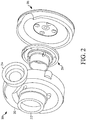
FIG. 2 generally illustrates an exploded perspective view of a multi-piece compressor housing according to the principles of the present disclosure. -
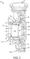
FIG. 3 generally illustrates a cross-section view of a multi-piece compressor housing according to the principles of the present disclosure. -
FIG. 4A generally illustrates a rear view of an outer housing structure of a compressor housing according to the principles of the present disclosure. -
FIG. 4B generally illustrates a cross-section view of the outer housing structure ofFIG. 4 . -
FIG. 5A generally illustrates a perspective view of an inner housing structure of a compressor housing according to the principles of the present disclosure. -
FIG. 5B generally illustrates a cross-section view of the inner housing structure ofFIG. 5A . -
FIG. 6A generally illustrates a front perspective view of a rear housing structure of a compressor housing according to the principles of the present disclosure. -
FIG. 6B generally illustrates a rear perspective view of the rear housing structure ofFIG. 6A . - Disclosed here are embodiments of a compressor housing for a turbocharger, which is formed of multiple components. By being formed of multiple components, difficulties associated with manufacturing compressor housings having unitary construction may be avoided. The multiple components of the compressor housing may, for example, be manufactured with die casting and/or injection molding, which may provide faster cycle times and reuse of dies, as compared to sand casting. The multiple components may also be machined with higher quality (e.g., surface finish, finer detail, etc.) and/more easily than compressor housing having unitary construction (e.g., within the volute).
- A multi-piece or parted compressor housing of a turbocharger, according to the principles of the present disclosure, is provided. The multi-piece compressor housing may be adapted as a drop fit replacement for a compressor housing having a unitary construction. For example, the multi-piece compressor housing may be adapted to connect to a turbocharger in the same or substantially the same way as a compressor housing having a unitary construction. The multi-piece compressor housing may provide improved performance (e.g., efficiency) from improved manufacturability due to the multi-piece configuration as compared to those having a unitary construction.
- The compressor housing, for example, includes various functional features, which may be formed individually or cooperatively by various structural components of the compressor housing. The functional features of the compressor housing include, for example, an inlet for receiving air, a wheel cavity in which the compressor wheel is rotated to compress the air, and a volute from which compressed air is expelled. Functional features of the compressor housing may also include a recirculating chamber and a noise attenuating feature. The structural components, which form the functional features of the compressor housing, include an outer housing structure, an inner housing structure, and a rear housing structure. In some embodiments, the inlet is formed by the outer housing structure and the inner housing structure, the wheel cavity is formed by the inner housing structure and the rear housing structure, and the volute is formed by the outer housing structure, the inner housing structure, and the rear housing structure. The recirculation cavity may be formed by the outer housing structure and the inner housing structure. The noise attenuating feature may be formed by the outer housing structure.
- The structural components may be formed with reusable tools, such as a die or an injection mold. The structural components may further have open configurations, which provide access for subsequent machining (e.g., sanding, finishing, threading, etc.). Open configurations, for example, include those configurations having surfaces that may face toward tooling for machining (e.g., facing toward or parallel with a plane and not away from such plane, such as by having no undercut surfaces). As a result, the compressor housing having multiple structural components may be manufactured with improved quality (e.g., surface finishing), reduced cost, and/or reduced time as compared to compressor housings that are functionally similar but have a unitary construction.
-
FIG. 1 generally illustrates a perspective partial cross-section view of aturbocharger 100 for a compressor housing according to the principles of the present disclosure may be adapted to be used (e.g., thecompressor housing 200 shown inFIGS. 2-6B ). Theturbocharger 100, as shown, is an exhaust-gas driven forced induction device that is utilized in conjunction with an internal combustion engine (not shown). Theturbocharger 100 includes aturbine wheel 110 that is in aturbine housing 120, which functions as a drive source. Theturbine housing 120 includes anexhaust gas inlet 122 for receiving exhaust gas from the internal combustion engine. Exhaust gases are routed from theexhaust gas inlet 122 to theturbine wheel 110 before exiting theturbine housing 120 at anexhaust gas outlet 123. Awastegate 124 may be mounted in theturbine housing 120 to allow some or all the exhaust gas to bypass theturbine wheel 110. Thewastegate 124 is movable between an open position and a closed position by an electriclinear actuator 130. Alternatively, theturbocharger 100 may instead or additionally another drive source, such as an electric motor used alone or in conjunction with the turbine wheel. - The
turbocharger 100 includes acompressor wheel 140 located in a cavity ofcompressor housing 150. Thecompressor housing 150 includes anintake air inlet 152 and a volute 154 that forms an air outlet. Intake air is routed from theintake air inlet 152 to thecompressor wheel 140, where the intake air is pressurized by rotation of thecompressor wheel 140. The air then exits thecompressor housing 150 through the volute 154 to be supplied to the internal combustion engine. - Rotation of the
compressor wheel 140 is driven by rotation of theturbine wheel 110. In particular, theturbine wheel 110 and thecompressor wheel 140 are each connected to ashaft 160. Theshaft 160 can be a substantially rigid member, and theturbine wheel 110 and thecompressor wheel 140 can be connected to theshaft 160 in a manner that prevents rotation of theturbine wheel 110 and thecompressor wheel 140 with respect to theshaft 160. As a result, thecompressor wheel 140 can rotate in unison with theturbine wheel 110 in response to rotation of theturbine wheel 110. - The
shaft 160 is supported within a bearinghousing 170 such that theshaft 160 may rotate freely with respect to the bearinghousing 170 at a very high rotational speed. The bearinghousing 170, theturbine housing 120, and thecompressor housing 150 are arranged along an axis of rotation of theshaft 160. In particular, the bearinghousing 170 is positioned between theturbine housing 120 and thecompressor housing 150. A first end of the bearinghousing 170 connected to theturbine housing 120, and a second end of the bearinghousing 170 connected to thecompressor housing 150. The bearinghousing 170 can incorporate lubrication and /or cooling features. - The bearing
housing 170 defines a cavity, which contains theshaft 160 and athrust bearing 190. The cavity may be closed by an oil seal plate 180 (e.g., cover, closure, etc.). Theshaft 160, thethrust bearing 190, and theoil seal plate 180 function to cooperatively transfer axial force (e.g., axial loading) from theturbine wheel 110 to the bearinghousing 170 and, thereby, locate theshaft 160 axially relative to the bearinghousing 170. - With reference to
FIGS. 2 and3 , acompressor housing 200, according to the principles of the present disclosure, is generally illustrated. Thecompressor housing 200 may be adapted for use with theturbocharger 100 in place of thecompressor housing 150. Thecompressor housing 200 forms anair inlet 212, awheel cavity 216 in which thecompressor wheel 140 rotates, and avolute 208 extending to anair outlet 214. Thecompressor housing 200 additionally includes arecirculation cavity 218 and a noise attenuation feature 220 (e.g., a noise attenuation device or "NAD"). Theair inlet 212 receives intake air in an axial direction. Thewheel cavity 216 has a surface profile corresponding to thecompressor wheel 140, receives air axially from theair inlet 212, and expels air radially to thevolute 208. Thevolute 208 forms a cavity that extends circumferentially around thecompressor wheel 140 and has a cross-sectional shape (e.g., circular) that gradually increases in size (e.g., diameter) until reaching theair outlet 214. These and other features of thecompressor housing 200 are discussed in further detail below. Thecompressor housing 200 may also be referred to as a multi-piece compressor housing or a compressor housing assembly, while thevolute 208 may also be referred to as a volute portion, and theair inlet 212 may be referred to as an inlet portion. - The
compressor housing 200 is formed by structural components that include an outer housing structure 202 (e.g., an outer shell or front cover), an inner housing structure 204 (e.g., an insert), and a rear housing structure 206 (e.g., a rear cover). Theouter housing structure 202, theinner housing structure 204, and therear housing structure 206 are structures (e.g., unitary members) that are formed separately from each other and that are coupled together to form thecompressor housing 200. As discussed in further detail below, theair inlet 212 is cooperatively formed by theouter housing structure 202 and theinner housing structure 204, thewheel cavity 216 is cooperatively formed by theinner housing structure 204 and therear housing structure 206, and thevolute 208 is cooperatively formed by theouter housing structure 202, theinner housing structure 204, and therear housing structure 206. Thevolute 208 is adapted to provide the same or substantially the same characteristics as a volute of a housing having a unitary construction. For example, thevolute 208 is adapted to provide the same or improved efficiency for expelling ambient air as a volute of a compressor housing having a unitary construction. Therecirculation cavity 218 is formed cooperatively by theouter housing structure 202 and theinner housing structure 204. Thenoise attenuation feature 220 is formed by theouter housing structure 202. - The
outer housing structure 202, theinner housing structure 204, and therear housing structure 206 are adapted to cooperatively interconnect to form and/or define thecompressor housing 200. For example, theouter housing structure 202 is adapted to receive theinner housing structure 204 and therear housing structure 206. Theinner housing structure 204 is adapted to securely fit within and couple to an inner portion of theouter housing structure 202. For example, an axial surface of theinner housing structure 204 is adapted to mate with a corresponding surface of theouter housing structure 202. Therear housing structure 206 is adapted to securely fit within and couple to an outer portion therear housing structure 206 to enclose theinner housing structure 204 therebetween. For example, an exterior profile of therear housing structure 206 is adapted to mate with an interior profile of theouter housing structure 202. These and other aspects of theouter housing structure 202, theinner housing structure 204, and therear housing structure 206 are discussed in further detail below. -
FIGS. 4A and 4B generally illustrate theouter housing structure 202 according to the principles of the present disclosure. Theouter housing structure 202 generally includes atubular portion 202a and aradial portion 202b that extends radially outward from thetubular portion 202a, which are formed as a singular or unitary structure. Thetubular portion 202a forms a portion of theair inlet 212 and has received therein theinner housing structure 204 to define therecirculation cavity 218. Thetubular portion 202a may also form thenoise attenuation feature 220. Anintermediate portion 202c, which extends between thetubular portion 202a and theradial portion 202b, is mated with and coupled to theinner housing structure 204. Theradial portion 202b forms a portion of thevolute 208, and further defines a recess in which therear housing structure 206 is received. These and other aspects of theouter housing structure 202 are discussed in further detail below. Theouter housing structure 202 may also be referred to as an outer shell or an outer housing member. Thetubular portion 202a may also be referred to as an inlet portion. Theradial portion 202b may also be referred to as a volute portion. - The
tubular portion 202a of theouter housing structure 202 forms afirst portion 212a (e.g., opening) of theair inlet 212 through which intake air first enters thecompressor housing 200. For example, thetubular portion 202a is adapted to be connected to a hose of an air source. An outercircumferential surface 222 of thetubular portion 202a may be coupled to the hose of the air source (e.g., receiving the hose thereon). Thefirst portion 212a of theair inlet 212 is disposed on a side of theouter housing structure 202 that faces away from theinner housing structure 204. - The
tubular portion 202a of theouter housing structure 202 also defines a portion of therecirculation cavity 218. Thetubular portion 202a includes an innercircumferential surface 224. Atubular portion 204a of theinner housing structure 204 is received within thetubular portion 202a. As discussed in further detail below therecirculation cavity 218 is defined between the innercircumferential surface 224 of thetubular portion 202a of theouter housing structure 202 and an outercircumferential surface 226 of atubular portion 204a of theinner housing structure 204. The outercircumferential surface 222 and the innercircumferential surface 224 of thetubular portion 202a of theouter housing structure 202 may be concentric or substantially concentric to one another (e.g., with the tubular portion having a constant wall thickness). Further aspects of therecirculation cavity 218 are discussed below in conjunction with theinner housing structure 204. - The
tubular portion 202a of theouter housing structure 202 may further form thenoise attenuation feature 220. Thefirst portion 212a of theair inlet 212 may be considered to include thenoise attenuation feature 220. Thenoise attenuation feature 220 is adapted to reduce and/or eliminate noise generated by components of theturbocharger 100, such as thecompressor wheel 140 ofFIG. 1 (e.g., blade noise generated during rotation of the compressor wheel 140) and air being drawn in through thefirst portion 212a of the air inlet 212 (e.g., a high pitched or whistling noise, or other noise). - The
noise attenuation feature 220 is disposed at a distal end (e.g., a first or forward end, or an entry) of theair inlet 212 and extends circumferentially around thefirst portion 212a of theair inlet 212. In some embodiments, thenoise attenuation feature 220 is hook-shaped. For example, thenoise attenuation feature 220 extends circumferentially around thetubular portion 202a, extends radially inward of the innercircumferential surface 224 of thetubular portion 202a, and protrudes axially rearward (e.g., toward the rear housing structure 206). In some embodiments, the hooked shape of thenoise attenuation feature 220 is adapted to reduce turbulence of the ambient air being drawn into theair inlet 212. As the turbulence of the ambient air being drawn into theair inlet 212 is controlled, noise associated with the ambient air being drawn into theair inlet 212 is reduced and/or eliminated. - The hooked shape of the
noise attenuation feature 220 defines arecess 228 that is adapted to reduce and/or eliminate noise exiting theair inlet 212 of theturbocharger 100. For example, therecess 228 may be adapted to reduce certain audible frequencies, may be adapted to redirect sound waves exiting theair inlet 212, may be adapted to reduce and/or eliminate noise exiting theair inlet 212 in other suitable fashions, and/or a combination thereof. - As referenced above, the
intermediate portion 202c of theouter housing structure 202 is adapted to mate and couple with theinner housing structure 204. For example, as shown, theintermediate portion 202c of theouter housing structure 202 defines a recess in which anintermediate portion 204c of theinner housing structure 204 is received. The recess may, for example, be cylindrical and defined radially within an inner circumferential surface 230 having a larger diameter than the innercircumferential surface 224. The inner circumferential surface 230 may be coaxial with the innercircumferential surface 224 and extend a shorter axial distance. - The recess may be further defined by a first axially-facing surface 232 (e.g., radially inward, axially forward, or rearward facing surface) that extends outward from the inner
circumferential surface 224 to the inner circumferential surface 230. The first axially-facing surface 232 of theouter housing structure 202 may be configured to receive there against a first axially-facing surface 234 (e.g., axially forward, radially inward, or forward-facing surface) of theinner housing structure 204 and may be stepped (e.g., to radially locate the inner housing structure 204). - The
intermediate portion 202c additionally includes a second axially-facing surface 236 (e.g., radially outward, axially rearward, or rearward facing surface) that faces toward therear housing structure 206. The axially-facingsurface 234 has received there against a second axially-facing surface 238 (e.g., radially outer, axially rearward, or forward-facing surface) of aradial portion 204b of theinner housing structure 204. The second axially-facingsurface 238 may, for example, be substantially planar and/or substantially perpendicular to an axis of thetubular portion 202a. - The
outer housing structure 202 may additionally include alignment and/or coupling features associated with corresponding features of theinner housing structure 204. For example, a rear portion of thetubular portion 202a and/or theintermediate portion 202c may include one or more orientation pockets 240. The orientation pockets 240 are recesses that extend axially away from the first axially-facing surface 232 and radially outward from the innercircumferential surface 224. The orientation pockets 240 may terminate radially inward of the inner circumferential surface 230 defining the recess for matingly receiving theintermediate portion 204c of theinner housing structure 204. The orientation pockets 240 are adapted to guide theinner housing structure 204 into proper orientation (e.g., rotational position), for example, by receivingcorresponding orientation bosses 242 of theinner housing structure 204 when connected and/or secured to theouter housing structure 202. - The
outer housing structure 202 is additionally configured to receive fasteners for coupling theinner housing structure 204 thereto. Theouter housing structure 202 includes one or more threaded bores 244 (e.g., three) for receiving fasteners. The threaded bores 244, for example, are circumferentially spaced and positioned radially outward of the orientation pockets 240. The threaded bores 244 extend axially into the second axially-facing surface 236 (e.g., in theintermediate portion 202c of the outer housing structure 202). - As referenced above, the
outer housing structure 202 also forms a portion of the volute 208 (e.g., a forward portion). For example, theradial portion 202b of theouter housing structure 202 includes aninner surface 246 that defines a forward surface of acavity 210 of thevolute 208. For example, while thevolute 208 extends circumferentially (e.g., wraps) around thecompressor wheel 140 and has a cross-sectional shape having an axis, theinner surface 246 of theradial portion 202b of theouter housing structure 202 extends circumferentially around the axis of the cross-sectional shape of the volute 208 (e.g., approximately 160 degrees or more, which may vary at different locations around the compressor wheel 140). Theinner surface 246 may, for example, form the forwardmost surface defining thecavity 210 of thevolute 208. Thecavity 210 of thevolute 208 may also be referred to as a volute cavity. - As discussed in further detail below, surfaces of the
inner housing structure 204 and therear housing structure 206 define inner and rearward portions of thevolute 208. At various positions (e.g., all positions) along thevolute 208, theinner housing structure 204 may form a greater circumferential portion of the cross-sectional shape of the volute than those circumferential portions formed by theinner housing structure 204 and therear housing structure 206. - As referenced above, the
outer housing structure 202 also defines a recess for receiving and coupling to therear housing structure 206. The recess may be cylindrical and be defined within an innercircumferential surface 252. For example, theradial portion 202b of theouter housing structure 202 includes anannular portion 250 that extends rearward (i.e., away from theair inlet 212 and defines the innercircumferential surface 252. The innercircumferential surface 252 corresponds in size and shape to an outercircumferential surface 254 of therear housing structure 206, which may be stepped (e.g., increasing in diameter moving rearward). - The
outer housing structure 202 additionally includes one or more securing bores 256 disposed radially around an outer circumferential edge of theouter housing structure 202 and that are adapted to receive a portion of a conventional fastener. For example, the securing bores 256 may be threaded for receiving a threaded portion of a conventional fastener, for example, to secure thecompressor housing 200 to another portion of the turbocharger 100 (e.g., to the bearing housing 170). - In some embodiments, the
outer housing structure 202 is adapted to be machined in one fixation. For example, theouter housing structure 202, after being formed via a die casting process, is held in one position during the machining process. Additionally, or alternatively, theouter housing structure 202 is adapted to be machined without using a sand casting process. Further, theouter housing structure 202 is formed such that the inner surface 246 (i.e., defining thecavity 210 of the volute 208) is open and accessible by surface finishing tools during surface finishing processes that occur during manufacturing of theouter housing structure 202. The term "open," as used in this context, may refer to theinner surface 246 facing in a single axial direction, such that theinner surface 246 may face toward (and not away from) tooling for machining. This arrangement may allow for greater surface finishing characteristics than what is possible on a housing having a unitary construction. Accordingly, thecompressor housing 200 may have a greater operating efficiency than a housing having a unitary construction. -
FIGS. 5A and 5B generally illustrate theinner housing structure 204 according to the principles of the present disclosure. As referenced above, theinner housing structure 204 generally includes thetubular portion 204a and theradial portion 204b that extends radially outward from thetubular portion 204a, which are formed as a singular or unitary structure or member. Theinner housing structure 204 further includes theintermediate portion 204c that extends between and is continuously formed with thetubular portion 204a and theradial portion 204b. Thetubular portion 204a of theinner housing structure 204 forms theair inlet 212 and therecirculation cavity 218 cooperatively with thetubular portion 202a of theouter housing structure 202. Theradial portion 204b defines thewheel cavity 216 cooperatively with therear housing structure 206. Theradial portion 204b of theinner housing structure 204 forms thevolute 208 cooperatively with theouter housing structure 202 and therear housing structure 206. Theinner housing structure 204 may also be referred to as an insert or an inner housing member. Thetubular portion 204a may also be referred to as an inlet portion. The radial portion may also be referred to as a volute portion. - The
tubular portion 204a of theinner housing structure 204 defines asecond portion 212b of theair inlet 212. Thesecond portion 212b of theair inlet 212 is a tubular passage that is disposed axially rearward of thefirst portion 212a (e.g., opening) of theair inlet 212 formed by the forward end of thetubular portion 202a of theouter housing structure 202. More particularly, thesecond portion 212b of theair inlet 212 is defined by an innercircumferential surface 258 of thetubular portion 204a of theinner housing structure 204. Intake air flows through the air inlet 212 (i.e., through thefirst portion 212a and then thesecond portion 212b) to thewheel cavity 216. - The
tubular portion 204a of theinner housing structure 204 also defines therecirculation cavity 218. Therecirculation cavity 218 is in communication with proximal and distal ends of the air inlet 212 (e.g., proximal being near the opening of thefirst portion 212a of theair inlet 212 and distal being near the wheel cavity 216). Therecirculation cavity 218 permits air that has passed through theair inlet 212 to thewheel cavity 216 to circulate axially forward toward thefirst portion 212a of theair inlet 212 and back into the tubular passage of thesecond portion 212b of theair inlet 212. Therecirculation cavity 218 is arranged radially outward of thesecond portion 212b of theair inlet 212 between the outercircumferential surface 226 of thetubular portion 204a of theinner housing structure 204 and the innercircumferential surface 224 of thetubular portion 202a of theouter housing structure 202. The outercircumferential surface 226 and the innercircumferential surface 258 of thetubular portion 204a of theinner housing structure 204 may be concentric with each other. The outercircumferential surface 226 may further be concentric with the innercircumferential surface 224 of thetubular portion 202a of theouter housing structure 202, such that therecirculation cavity 218 has a substantially constant width moving circumferentially around the axis thereof and/or axially there along. - Air enters the
recirculation cavity 218 through a firstcircumferential opening 260 formed by theinner housing structure 204 and exits therecirculation cavity 218 through a secondcircumferential opening 262 defined between thefirst portion 212a of the air inlet 212 (e.g., by the noise attenuation feature 220) and thesecond portion 212b of the air inlet 212 (e.g., by an axial end of thetubular portion 204a of the inner housing structure 204). - The first
circumferential opening 260 is, for example, formed as a recirculation slot that extends circumferentially around and radially through thetubular portion 204a of the inner housing structure 204 (i.e., from the innercircumferential surface 258 to the outer circumferential surface 226). The firstcircumferential opening 260 is positioned proximate thewheel cavity 216 to provide a path for air flowing away from thecompressor wheel 140 into therecirculation cavity 218. This may prevent thecompressor wheel 140 from surging. The firstcircumferential opening 260 may also be referred to as a recirculation slot or recirculation cavity inlet. - The second
circumferential opening 262 is, for example, formed as a gap between ends of theouter housing structure 202 and theinner housing structure 204. The gap of thecircumferential opening 262 extends axially and/or radially between thenoise attenuation feature 220 of theouter housing structure 202 and the distal end of thetubular portion 204a of theinner housing structure 204. The secondcircumferential opening 262 may extend circumferentially entirely around the axis (e.g., wheel axis) of thecompressor wheel 140 and radially inward from an inner circumferential surface of thenoise attenuation feature 220 and from the innercircumferential surface 258 of theinner housing structure 204. The secondcircumferential opening 262 may also be referred to as a recirculation cavity outlet. - The
inner housing structure 204 cooperatively forms thevolute 208 with theouter housing structure 202 and therear housing structure 206, for example, forming an inward portion of thevolute 208. More particularly, an outer periphery of theradial portion 204b of theinner housing structure 204 includes anouter surface 272 that defines an inner portion of thecavity 210 of thevolute 208. Theouter surface 272 is adjacent to and extends generally continuously from theinner surface 246 of the outer housing structure 202 (e.g., transitioning smoothly to cooperatively form a partial circular cross-sectional shape of the volute 208). Theouter surface 272 extends circumferentially around the axis (e.g., the volute axis) of the cross-sectional shape of thevolute 208 less than theinner surface 246 of theouter housing structure 202. - The
inner housing structure 204 is adapted to be connected and/or secured to theouter housing structure 202. As referenced above, theinner housing structure 204 is received by the recess formed by theintermediate portion 202c of theouter housing structure 202 and is received against the first axially-facing surface 232 and/or the second axially-facingsurface 236 of theouter housing structure 202. More particularly, theintermediate portion 204c of theinner housing structure 204 forms a generally cylindrical protrusion that is received by theintermediate portion 202c. Theintermediate portion 204c forms the first axially-facingsurface 234 that is received against the first axially-facing surface 232 of theouter housing structure 202 and has a complementary profile thereto (e.g., being stepped), which may function to locate (e.g., align) theinner housing structure 204 relative to theouter housing structure 202. An outercircumferential surface 264 of theintermediate portion 204c is configured to mate with the inner circumferential surface 230 of the recess formed by theintermediate portion 202c of the outer housing structure 202 (e.g., having a complementary diameter). - The
inner housing structure 204 and theouter housing structure 202 may additionally be configured to form a seal therebetween. For example, a seal member 266 (e.g., an O-ring) may be arranged between the circumferential surfaces of theintermediate portion 204c of theinner housing structure 204 and theintermediate portion 202c of theouter housing structure 202. Theinner housing structure 204 may, for example, include acircumferential groove 268 in which theseal member 266 is received to be compressed therein and against the inner circumferential surface 230 of theintermediate portion 202c of theouter housing structure 202. - The
radial portion 204b of theinner housing structure 204 is additionally received against theradial portion 202b of theouter housing structure 202. Theradial portion 204b forms the second axially-facingsurface 238 that is received against the second axially-facingsurface 236 of theradial portion 202b of theouter housing structure 202. The second axially-facingsurface 238 of theinner housing structure 204 has a complementary profile (e.g., being generally planar) to the second axially-facingsurface 236 of theradial portion 202b of theouter housing structure 202. - As referenced above, the
inner housing structure 204 includes one ormore orientation bosses 242 that protrude from surrounding portions (e.g., the outer circumferential surface 226) to be received by respective orientation pockets 240 of theouter housing structure 202. Theorientation bosses 242 and the orientation pockets 240 cooperatively operate to properly align theinner housing structure 204 with respect to theouter housing structure 202 when theinner housing structure 204 is connected and/or secured to theouter housing structure 202. Theorientation bosses 242 extend radially outward of thetubular portion 204a and axially forward of theradial portion 204b of theinner housing structure 204. The orientation bosses may also be referred to as protrusions. - As shown in
FIGS. 3 and5A-5B , the firstcircumferential opening 260 may extend into theorientation bosses 242. As a result, thetubular portion 204a (e.g., forming tubular passage of the air inlet 212) is connected to theradial portion 204b by way of the orientation bosses 242 (e.g., by only the orientation bosses 242). The firstcircumferential opening 260, may, for example, extend at a non-perpendicular angle (e.g., between 30 and 60 degrees, such as approximately 45 degrees) relative to thetubular portion 204a of the inner housing structure 204 (e.g., relative to the innercircumferential surface 258, the outercircumferential surface 226, and/or the axis of the compressor wheel 140). - The
inner housing structure 204 is additionally configured to connect to the outer housing structure 202 (e.g., with fasteners). Theinner housing structure 204 includes one or more through bores 270 (e.g., three) that are adapted to receive a portion of a conventional fastener (e.g., screw). For example, a fastener (not shown) may pass through the throughbores 270 and be received by securingbores 244 of the outer housing structure 202 (seeFIG. 4A ) corresponding thereto. The through bores 270 are, for example, circumferentially-spaced about and extend axially through theradial portion 204b of theinner housing structure 204. - In some embodiments, the
inner housing structure 204 is adapted to be machined in one fixation. For example, theinner housing structure 204 may be held in one position during the machining process. Additionally, or alternatively, theinner housing structure 204 is adapted to be machined without using a sand medium. Theinner housing structure 204 includes an open design that provides access for surface finishing during manufacturing of the inner housing structure 204 (e.g., forming theouter surface 272 that defines thecavity 210 of the volute 208). The term "open," as used in this context, may refer to theouter surface 272 facing in a single axial direction, such that theouter surface 272 may face toward (and not away) from tooling for machining. This arrangement may allow for greater surface finishing characteristics than what is possible on a housing having a unitary construction. Accordingly, thecompressor housing 200 may have a greater operating efficiency than a housing having a unitary construction. -
FIGS. 6A and 6B generally illustrate therear housing structure 206 according to the principles of the present disclosure. Therear housing structure 206 generally includes aninner radial portion 206a and an outerradial portion 206b. Therear housing structure 206 may have a generally cylindrical configuration. Theinner radial portion 206a forms a rearward surface of thewheel cavity 216 for thecompressor wheel 140. The outerradial portion 206b forms another portion of thevolute 208. The outerradial portion 206b is received by theradial portion 202b of theouter housing structure 202. Further aspects of therear housing structure 206 are discussed in further detail below. Theinner radial portion 206a may also be referred to as a cavity or wheel cavity portion. The outerradial portion 206b may also be referred to as a volute portion. - The
inner radial portion 206a of therear housing structure 206 defines thewheel cavity 216 in cooperation with theinner housing structure 204, for example, by forming a rear wall thereof. Theinner radial portion 206a may, for example, form a recess in which a back wall of thecompressor wheel 140 is arranged and in which thecompressor wheel 140 rotates. Theinner radial portion 206a includes ashaft bore 274 through which theshaft 160 extends into thecompressor housing 200 to be coupled to thecompressor wheel 140. - The outer
radial portion 206b of therear housing structure 206 forms another portion of thevolute 208. For example, the outerradial portion 206b may form a rear portion of thevolute 208 by including aninner surface 276 is adjacent to and extends generally continuously from theinner surface 246 of the radial portion outer housing structure 202 (e.g., transitioning smoothly to cooperatively form a partial circular cross-sectional shape of the volute 208). An outer portion of theinner surface 276 extends circumferentially around the axis of the cross-sectional shape of thevolute 208, for example, a lesser distance than theinner surface 246 of theouter housing structure 202 and a greater distance than theouter surface 272 of theinner housing structure 204. Moving radially inward, theinner surface 276 of the outerradial portion 206b straightens (e.g., increases in radius, such as becoming planar) and is spaced apart from a rear axially-facingsurface 278 of theinner housing structure 204 to form the radial inlet for air to exit thewheel cavity 216 and enter thevolute 208. - The outer
radial portion 206b of therear housing structure 206 further includes a radial channel 280 (e.g., cutaway) that extends radially outward from theinner surface 276 and to an outercircumferential surface 282 of therear housing structure 206. Theradial channel 280 is in communication and/or aligns with theair outlet 214 when therear housing structure 206 is connected and/or secured to theouter housing structure 202. For example, compressed air expelled out radially through thevolute 208, as described above inFIGS. 2 and3 , may exit thecavity 210 of thevolute 208 through theradial channel 280 before exiting thecompressor housing 200 through theair outlet 214. - The
rear housing structure 206 is configured to be received by theouter housing structure 202 to couple thereto. As referenced above, therear housing structure 206 is received by a recess defined by theradial portion 202b of the outer housing structure 202 (e.g., by theannular portion 250 that extends rearward). In some embodiments, the outercircumferential surface 282 is adapted to be received by a corresponding interior profile (e.g., recess) of theouter housing structure 202, such that, therear housing structure 206 fits securely within theouter housing structure 202. For example, the outercircumferential surface 282 may have a corresponding shape (e.g., diameter) to the innercircumferential surface 252 of theouter housing structure 202 for therear housing structure 206 to be received in theouter housing structure 202. The outercircumferential surface 282 may, as shown, be stepped, reducing in diameter in a stepped manner moving axially forward. A seal member 284 may also be arranged (e.g., compressed) radially between therear housing structure 206 and the outer housing structure 202 (e.g., in acircumferential groove 286 in the outer circumferential surface 254). Therear housing structure 206 may, in some embodiments, be coupled to theinner housing structure 204 only indirectly via the outer housing structure 202 (e.g., being spaced apart axially therefrom). - The
rear housing structure 206 may additionally be adapted to connect and/or secure to another portion of theturbocharger 100, for example, the bearinghousing 170. For example, therear housing structure 206 includes one or more throughbores 288. The through bores 288 are adapted to receive a portion of a conventional fastener. For example, a conventional fastener may be inserted into a first side (e.g., forward side) of the throughbore 288 and may pass through the through bore 288 (e.g., rearward). In some embodiments, the conventional fastener may be received by a corresponding securing bore of the structure (e.g., the bearing housing) mated thereto. - In some embodiments, the
rear housing structure 206 is adapted to be machined in one fixation. For example, therear housing structure 206 is held in one position during the machining process. Additionally, or alternatively, therear housing structure 206 is adapted to be machined without using a sand medium. Therear housing structure 206 includes an open design that provides access for surface finishing during manufacturing of the rear housing structure 206 (e.g., forming theinner surface 276 that defines thecavity 210 of the volute 208). The term "open," as used in this context, may refer to theinner surface 276 facing in a single axial direction, such that theinner surface 276 may face toward (and not away) from tooling for machining. This arrangement may allow for greater surface finishing characteristics than what is possible on a housing having a unitary construction. Accordingly, thecompressor housing 200 may have a greater operating efficiency than a housing having a unitary construction. - As used herein, the terminology "or" is intended to mean an inclusive "or" rather than an exclusive "or". That is, unless specified otherwise, or clear from context, "X includes A or B" is intended to indicate any of the natural inclusive permutations. That is, if X includes A; X includes B; or X includes both A and B, then "X includes A or B" is satisfied under any of the foregoing instances. In addition, the articles "a" and "an" as used in this application and the appended claims should generally be construed to mean "one or more" unless specified otherwise or clear from context to be directed to a singular form.
- Furthermore, where similar terms are used to identify different components or features, identifying terms, such as "first," "second," "another," or "other", may be used to distinguish such components or features in the claims. For example, the
tubular portion 202a of theouter housing structure 202 may be identified as a "first tubular portion," while thetubular portion 204a of theinner housing structure 204 may be identified as a "second tubular portion." - Further, for simplicity of explanation, although the figures and descriptions herein may include sequences or series of steps or stages, elements of the methods disclosed herein may occur in various orders or concurrently. Additionally, elements of the methods disclosed herein may occur with other elements not explicitly presented and described herein. Furthermore, not all elements of the methods described herein may be required to implement a method in accordance with this disclosure. Although aspects, features, and elements are described herein in particular combinations, each aspect, feature, or element may be used independently or in various combinations with or without other aspects, features, and elements.
- While the disclosure has been described in connection with certain embodiments, it is to be understood that the disclosure is not to be limited to the disclosed embodiments but, on the contrary, is intended to cover various modifications and equivalent arrangements included within the scope of the appended claims, which scope is to be accorded the broadest interpretation so as to encompass all such modifications and equivalent structures as is permitted under the law.
Claims (15)
- A compressor housing (200) for a turbocharger (100) comprising:an outer housing structure (202) having a first tubular portion (202a) and a first radial portion (202b) extending radially outward of the first tubular portion (202a);an inner housing structure (204) having a second tubular portion (204a) and a second radial portion (204b) extending radially outward of the second tubular portion (204a); anda rear housing structure (206) having an inner radial portion (206a) and an outer radial portion (206b) extending radially outward of the inner radial portion (206a);wherein the outer housing structure (202), the inner housing structure (204), and the rear housing structure (206) are formed separately from each other and are coupled to each other, a recirculation cavity (218) is defined radially between the first tubular portion (202a) and the second tubular portion (204a), and a volute (208) is cooperatively formed by the first radial portion (202b) and the outer radial portion (206b).
- The compressor housing (200) according to claim 1, wherein the first tubular portion (202a) and the second tubular portion (204a) cooperatively form an inlet (212) having an inlet opening (212a) and a tubular passage (212b) that communicate air to a wheel cavity (216).
- The compressor housing (200) according to claim 2, wherein the recirculation cavity (218) has a distal opening proximate the inlet opening (212a) and a proximal opening proximate the wheel cavity (216).
- The compressor housing (200) according to claim 3, wherein the distal opening extends circumferentially around an axis of the tubular passage (212b) and axially between the outer housing structure (202) and the inner housing structure (204).
- The compressor housing (200) according to claim 4, wherein the first tubular portion (202a) includes a noise attenuation feature (220), and the distal opening is between the noise attenuation feature (220) and a forward end of the second tubular portion (204a).
- The compressor housing (200) according to claim 3, wherein the proximal opening extends circumferentially around an axis of the tubular passage (212b) and radially through the second tubular portion (204a).
- The compressor housing (200) according to claim 6, wherein the inner housing structure (204) includes protrusions (242) that extend radially outward of the second tubular portion (204a), and the proximal opening is formed as a slot that extends partially into the protrusions (242).
- The compressor housing (200) according to claim 7, wherein the second tubular portion (204a) is connected to the second radial portion (204b) by only the protrusions (242).
- The compressor housing (200) according to claim 3, wherein the recirculation cavity (218) surrounds the tubular passage (212b), the recirculation cavity (218) being defined between an inner circumferential surface (202) of the first tubular portion (202a) and an outer circumferential surface (222) of the second tubular portion (204a), and the tubular passage (212b) being defined by another inner circumferential surface (202) of the second tubular portion (204a).
- The compressor housing (200) according to claim 1, wherein the volute (208) is cooperatively formed by the first radial portion (202b), the second radial portion (204b), and the outer radial portion (206b);
wherein the first radial portion (202b) forms a forward portion of the volute (208), the second radial portion (204b) forms an inner portion of the volute (208), and the outer radial portion (206b) forms a rearward portion of the volute (208). - The compressor housing (200) according to claim 10, wherein the volute (208) forms a volute cavity (210) that extends circumferentially around a wheel axis of a wheel cavity (216) and has a cross-sectional shape having a volute axis; and
wherein the first radial portion (204b) includes a first inner surface, the second radial portion (204b) includes an outer surface (272), and the outer radial portion (206b) includes a second inner surface, which cooperatively define the volute cavity (210). - The compressor housing (200) according to claim 11, wherein the first inner surface extends circumferentially around the volute axis more than the outer surface (272) and the second inner surface.
- The compressor housing (200) according to claim 12, wherein the second inner surface extends circumferentially around the volute axis more than the outer surface (272).
- The compressor housing (200) according to claim 11, wherein the outer surface (272) is adjacent to the first inner surface and the first inner surface is adjacent to the second inner surface to cooperatively form a cross-sectional shape of the volute (208).
- The compressor housing (200) according to claim 1, wherein the outer housing structure (202) defines a first recess (268) that is cylindrical and in which the inner housing structure (204) is received to form a seal (266) therebetween, and defines a second recess (286) that is cylindrical in which the rear housing structure (206) is received to form another seal (284) therebetween.
Applications Claiming Priority (1)
| Application Number | Priority Date | Filing Date | Title |
|---|---|---|---|
| US15/786,101 US10519974B2 (en) | 2017-10-17 | 2017-10-17 | Multi-piece compressor housing for a turbocharger |
Publications (2)
| Publication Number | Publication Date |
|---|---|
| EP3473862A1 true EP3473862A1 (en) | 2019-04-24 |
| EP3473862B1 EP3473862B1 (en) | 2020-11-18 |
Family
ID=63857750
Family Applications (1)
| Application Number | Title | Priority Date | Filing Date |
|---|---|---|---|
| EP18200282.4A Active EP3473862B1 (en) | 2017-10-17 | 2018-10-13 | Multi-piece compressor housing for a turbocharger |
Country Status (5)
| Country | Link |
|---|---|
| US (1) | US10519974B2 (en) |
| EP (1) | EP3473862B1 (en) |
| JP (1) | JP2019074087A (en) |
| KR (1) | KR20190043099A (en) |
| CN (1) | CN109667794A (en) |
Cited By (1)
| Publication number | Priority date | Publication date | Assignee | Title |
|---|---|---|---|---|
| SE2151219A1 (en) * | 2021-10-05 | 2023-04-06 | Scania Cv Ab | Compressor Arrangement, Turbocharger, Combustion Engine, and Vehicle |
Families Citing this family (5)
| Publication number | Priority date | Publication date | Assignee | Title |
|---|---|---|---|---|
| US10690144B2 (en) * | 2017-06-27 | 2020-06-23 | Garrett Transportation I Inc. | Compressor housings and fabrication methods |
| JP6848890B2 (en) * | 2018-01-23 | 2021-03-24 | 株式会社豊田自動織機 | Turbocharger |
| DE102018102704A1 (en) * | 2018-02-07 | 2019-08-08 | Man Energy Solutions Se | centrifugal compressors |
| CN111075768A (en) * | 2019-12-20 | 2020-04-28 | 中国北方发动机研究所(天津) | Centrifugal compressor volute with auxiliary noise reduction structure |
| CN115143086B (en) * | 2022-08-15 | 2023-05-30 | 哈尔滨工程大学 | Air-intake bypass recirculation structure with adjustable air-entraining amount and controllable broadband noise |
Citations (5)
| Publication number | Priority date | Publication date | Assignee | Title |
|---|---|---|---|---|
| JP2003074360A (en) * | 2001-09-05 | 2003-03-12 | Ishikawajima Harima Heavy Ind Co Ltd | Exhaust turbine supercharger |
| CN101737359A (en) * | 2010-02-09 | 2010-06-16 | 清华大学 | Asymmetric self-circulation processing case with slotting position of sine distribution for centrifugal compressor |
| CN102588351A (en) * | 2012-01-03 | 2012-07-18 | 大同北方天力增压技术有限公司 | Low-noise device for centrifugal compressor of turbocharger |
| EP2486284A2 (en) * | 2009-10-08 | 2012-08-15 | Honeywell International Inc. | Low-noise ported-shroud compressor for a turbocharger |
| WO2013191937A1 (en) * | 2012-06-18 | 2013-12-27 | Borgwarner Inc. | Compressor cover for turbochargers |
Family Cites Families (16)
| Publication number | Priority date | Publication date | Assignee | Title |
|---|---|---|---|---|
| US4521155A (en) | 1978-06-19 | 1985-06-04 | Osborn Norbert L | Turbocharger compressor housing |
| DE4027174A1 (en) * | 1990-08-28 | 1992-03-05 | Kuehnle Kopp Kausch Ag | MAP STABILIZATION WITH A RADIAL COMPRESSOR |
| US5246335A (en) * | 1991-05-01 | 1993-09-21 | Ishikawajima-Harimas Jukogyo Kabushiki Kaisha | Compressor casing for turbocharger and assembly thereof |
| US5295785A (en) * | 1992-12-23 | 1994-03-22 | Caterpillar Inc. | Turbocharger having reduced noise emissions |
| DE19647605C2 (en) * | 1996-11-18 | 1999-03-11 | Daimler Benz Ag | Exhaust gas turbocharger for internal combustion engines |
| US6193463B1 (en) | 1999-06-30 | 2001-02-27 | Alliedsignal, Inc. | Die cast compressor housing for centrifugal compressors with a true volute shape |
| US7179051B2 (en) | 2004-11-19 | 2007-02-20 | Consolidated Metco. Inc. | Method of die casting compressor housings |
| US7568338B2 (en) | 2005-12-23 | 2009-08-04 | Honeywell International Inc. | Multi-piece compressor housing |
| US7624575B2 (en) * | 2006-12-08 | 2009-12-01 | Honeywell International Inc. | EGR mixer and ported shroud compressor housing |
| DE102007027282B3 (en) | 2007-06-11 | 2008-11-13 | Woco Industrietechnik Gmbh | Plastic compressor housing and method for producing a plastic compressor housing |
| US10273973B2 (en) * | 2010-02-09 | 2019-04-30 | Ihi Corporation | Centrifugal compressor having an asymmetric self-recirculating casing treatment |
| JP5985329B2 (en) | 2012-09-21 | 2016-09-06 | 株式会社オティックス | Turbocharger and manufacturing method thereof |
| US9482240B2 (en) | 2013-07-31 | 2016-11-01 | Honeywell International Inc. | Compressor housing assembly for a turbocharger |
| WO2015077380A1 (en) | 2013-11-25 | 2015-05-28 | Borgwarner Inc. | Two piece compressor housing |
| JP6062888B2 (en) | 2014-07-07 | 2017-01-18 | トヨタ自動車株式会社 | Turbocharger |
| US9951793B2 (en) * | 2016-06-01 | 2018-04-24 | Borgwarner Inc. | Ported shroud geometry to reduce blade-pass noise |
-
2017
- 2017-10-17 US US15/786,101 patent/US10519974B2/en active Active
-
2018
- 2018-10-13 EP EP18200282.4A patent/EP3473862B1/en active Active
- 2018-10-16 KR KR1020180123120A patent/KR20190043099A/en not_active Withdrawn
- 2018-10-16 JP JP2018194779A patent/JP2019074087A/en active Pending
- 2018-10-17 CN CN201811208377.0A patent/CN109667794A/en active Pending
Patent Citations (5)
| Publication number | Priority date | Publication date | Assignee | Title |
|---|---|---|---|---|
| JP2003074360A (en) * | 2001-09-05 | 2003-03-12 | Ishikawajima Harima Heavy Ind Co Ltd | Exhaust turbine supercharger |
| EP2486284A2 (en) * | 2009-10-08 | 2012-08-15 | Honeywell International Inc. | Low-noise ported-shroud compressor for a turbocharger |
| CN101737359A (en) * | 2010-02-09 | 2010-06-16 | 清华大学 | Asymmetric self-circulation processing case with slotting position of sine distribution for centrifugal compressor |
| CN102588351A (en) * | 2012-01-03 | 2012-07-18 | 大同北方天力增压技术有限公司 | Low-noise device for centrifugal compressor of turbocharger |
| WO2013191937A1 (en) * | 2012-06-18 | 2013-12-27 | Borgwarner Inc. | Compressor cover for turbochargers |
Cited By (4)
| Publication number | Priority date | Publication date | Assignee | Title |
|---|---|---|---|---|
| SE2151219A1 (en) * | 2021-10-05 | 2023-04-06 | Scania Cv Ab | Compressor Arrangement, Turbocharger, Combustion Engine, and Vehicle |
| WO2023059245A1 (en) * | 2021-10-05 | 2023-04-13 | Scania Cv Ab | Compressor arrangement, turbocharger, combustion engine, and vehicle |
| SE545238C2 (en) * | 2021-10-05 | 2023-06-07 | Scania Cv Ab | Compressor Arrangement, Turbocharger, Combustion Engine, and Vehicle |
| US12196216B2 (en) | 2021-10-05 | 2025-01-14 | Scania Cv Ab | Compressor arrangement, turbocharger, combustion engine, and vehicle |
Also Published As
| Publication number | Publication date |
|---|---|
| EP3473862B1 (en) | 2020-11-18 |
| US20190113050A1 (en) | 2019-04-18 |
| KR20190043099A (en) | 2019-04-25 |
| CN109667794A (en) | 2019-04-23 |
| JP2019074087A (en) | 2019-05-16 |
| US10519974B2 (en) | 2019-12-31 |
Similar Documents
| Publication | Publication Date | Title |
|---|---|---|
| EP3473862B1 (en) | Multi-piece compressor housing for a turbocharger | |
| JP4047330B2 (en) | Independent passage diffuser | |
| US10302012B2 (en) | Variable nozzle unit and variable geometry system turbocharger | |
| US10436218B2 (en) | Compressor cover, centrifugal compressor, and turbocharger, and compressor cover manufacturing method | |
| EP1753961B1 (en) | Compressor apparatus with recirculation and method therefore | |
| CN107076015B (en) | The manufacturing method of turbine shroud and turbine shroud | |
| EP2832974B1 (en) | Compressor housing assembly for a turbocharger | |
| EP2400127B1 (en) | Turbo supercharger | |
| WO2015066301A1 (en) | Noise attenuation device for compressor inlet duct | |
| CN107035528A (en) | For compressor and the method and system of turbine cooling | |
| EP1806489B1 (en) | Exhaust gas turbine supercharger | |
| JP2005180452A (en) | Method and apparatus for machining component parts | |
| WO2014047516A1 (en) | Hydraulic system with modular inserts | |
| EP3061975B1 (en) | Axial compressor with flow recirculation | |
| US10280836B2 (en) | Variable nozzle unit and variable geometry system turbocharger | |
| CN104884761B (en) | Variable-nozzle unit and variable capacity type booster | |
| JP6844619B2 (en) | Supercharger | |
| US11098730B2 (en) | Deswirler assembly for a centrifugal compressor | |
| EP3351762B1 (en) | Variable nozzle unit and variable displacement-type supercharger | |
| US10184485B2 (en) | Method of manufacturing a compressor housing | |
| US20230392517A1 (en) | Housing | |
| CN113090347B (en) | Air starter with bearing cooling | |
| CN107035427B (en) | Variable nozzle assembly of turbocharger and assembly method thereof | |
| CN109790772B (en) | Closing element for closing a housing of a heat transfer fluid pump contained in an engine | |
| EP4286096B1 (en) | Abrasive flow machining process for a meridionally divided turbine housing, and a fixture used in said process |
Legal Events
| Date | Code | Title | Description |
|---|---|---|---|
| PUAI | Public reference made under article 153(3) epc to a published international application that has entered the european phase |
Free format text: ORIGINAL CODE: 0009012 |
|
| STAA | Information on the status of an ep patent application or granted ep patent |
Free format text: STATUS: THE APPLICATION HAS BEEN PUBLISHED |
|
| AK | Designated contracting states |
Kind code of ref document: A1 Designated state(s): AL AT BE BG CH CY CZ DE DK EE ES FI FR GB GR HR HU IE IS IT LI LT LU LV MC MK MT NL NO PL PT RO RS SE SI SK SM TR |
|
| AX | Request for extension of the european patent |
Extension state: BA ME |
|
| STAA | Information on the status of an ep patent application or granted ep patent |
Free format text: STATUS: REQUEST FOR EXAMINATION WAS MADE |
|
| 17P | Request for examination filed |
Effective date: 20191024 |
|
| RBV | Designated contracting states (corrected) |
Designated state(s): AL AT BE BG CH CY CZ DE DK EE ES FI FR GB GR HR HU IE IS IT LI LT LU LV MC MK MT NL NO PL PT RO RS SE SI SK SM TR |
|
| GRAP | Despatch of communication of intention to grant a patent |
Free format text: ORIGINAL CODE: EPIDOSNIGR1 |
|
| STAA | Information on the status of an ep patent application or granted ep patent |
Free format text: STATUS: GRANT OF PATENT IS INTENDED |
|
| INTG | Intention to grant announced |
Effective date: 20200528 |
|
| GRAS | Grant fee paid |
Free format text: ORIGINAL CODE: EPIDOSNIGR3 |
|
| GRAA | (expected) grant |
Free format text: ORIGINAL CODE: 0009210 |
|
| STAA | Information on the status of an ep patent application or granted ep patent |
Free format text: STATUS: THE PATENT HAS BEEN GRANTED |
|
| AK | Designated contracting states |
Kind code of ref document: B1 Designated state(s): AL AT BE BG CH CY CZ DE DK EE ES FI FR GB GR HR HU IE IS IT LI LT LU LV MC MK MT NL NO PL PT RO RS SE SI SK SM TR |
|
| REG | Reference to a national code |
Ref country code: GB Ref legal event code: FG4D |
|
| REG | Reference to a national code |
Ref country code: CH Ref legal event code: EP |
|
| REG | Reference to a national code |
Ref country code: IE Ref legal event code: FG4D |
|
| REG | Reference to a national code |
Ref country code: DE Ref legal event code: R096 Ref document number: 602018009823 Country of ref document: DE |
|
| REG | Reference to a national code |
Ref country code: AT Ref legal event code: REF Ref document number: 1336086 Country of ref document: AT Kind code of ref document: T Effective date: 20201215 |
|
| REG | Reference to a national code |
Ref country code: AT Ref legal event code: MK05 Ref document number: 1336086 Country of ref document: AT Kind code of ref document: T Effective date: 20201118 |
|
| REG | Reference to a national code |
Ref country code: NL Ref legal event code: MP Effective date: 20201118 |
|
| PG25 | Lapsed in a contracting state [announced via postgrant information from national office to epo] |
Ref country code: GR Free format text: LAPSE BECAUSE OF FAILURE TO SUBMIT A TRANSLATION OF THE DESCRIPTION OR TO PAY THE FEE WITHIN THE PRESCRIBED TIME-LIMIT Effective date: 20210219 Ref country code: NO Free format text: LAPSE BECAUSE OF FAILURE TO SUBMIT A TRANSLATION OF THE DESCRIPTION OR TO PAY THE FEE WITHIN THE PRESCRIBED TIME-LIMIT Effective date: 20210218 Ref country code: FI Free format text: LAPSE BECAUSE OF FAILURE TO SUBMIT A TRANSLATION OF THE DESCRIPTION OR TO PAY THE FEE WITHIN THE PRESCRIBED TIME-LIMIT Effective date: 20201118 Ref country code: RS Free format text: LAPSE BECAUSE OF FAILURE TO SUBMIT A TRANSLATION OF THE DESCRIPTION OR TO PAY THE FEE WITHIN THE PRESCRIBED TIME-LIMIT Effective date: 20201118 Ref country code: PT Free format text: LAPSE BECAUSE OF FAILURE TO SUBMIT A TRANSLATION OF THE DESCRIPTION OR TO PAY THE FEE WITHIN THE PRESCRIBED TIME-LIMIT Effective date: 20210318 |
|
| PG25 | Lapsed in a contracting state [announced via postgrant information from national office to epo] |
Ref country code: AT Free format text: LAPSE BECAUSE OF FAILURE TO SUBMIT A TRANSLATION OF THE DESCRIPTION OR TO PAY THE FEE WITHIN THE PRESCRIBED TIME-LIMIT Effective date: 20201118 Ref country code: BG Free format text: LAPSE BECAUSE OF FAILURE TO SUBMIT A TRANSLATION OF THE DESCRIPTION OR TO PAY THE FEE WITHIN THE PRESCRIBED TIME-LIMIT Effective date: 20210218 Ref country code: IS Free format text: LAPSE BECAUSE OF FAILURE TO SUBMIT A TRANSLATION OF THE DESCRIPTION OR TO PAY THE FEE WITHIN THE PRESCRIBED TIME-LIMIT Effective date: 20210318 Ref country code: LV Free format text: LAPSE BECAUSE OF FAILURE TO SUBMIT A TRANSLATION OF THE DESCRIPTION OR TO PAY THE FEE WITHIN THE PRESCRIBED TIME-LIMIT Effective date: 20201118 Ref country code: PL Free format text: LAPSE BECAUSE OF FAILURE TO SUBMIT A TRANSLATION OF THE DESCRIPTION OR TO PAY THE FEE WITHIN THE PRESCRIBED TIME-LIMIT Effective date: 20201118 Ref country code: SE Free format text: LAPSE BECAUSE OF FAILURE TO SUBMIT A TRANSLATION OF THE DESCRIPTION OR TO PAY THE FEE WITHIN THE PRESCRIBED TIME-LIMIT Effective date: 20201118 |
|
| REG | Reference to a national code |
Ref country code: LT Ref legal event code: MG9D |
|
| PG25 | Lapsed in a contracting state [announced via postgrant information from national office to epo] |
Ref country code: HR Free format text: LAPSE BECAUSE OF FAILURE TO SUBMIT A TRANSLATION OF THE DESCRIPTION OR TO PAY THE FEE WITHIN THE PRESCRIBED TIME-LIMIT Effective date: 20201118 |
|
| PG25 | Lapsed in a contracting state [announced via postgrant information from national office to epo] |
Ref country code: SK Free format text: LAPSE BECAUSE OF FAILURE TO SUBMIT A TRANSLATION OF THE DESCRIPTION OR TO PAY THE FEE WITHIN THE PRESCRIBED TIME-LIMIT Effective date: 20201118 Ref country code: RO Free format text: LAPSE BECAUSE OF FAILURE TO SUBMIT A TRANSLATION OF THE DESCRIPTION OR TO PAY THE FEE WITHIN THE PRESCRIBED TIME-LIMIT Effective date: 20201118 Ref country code: LT Free format text: LAPSE BECAUSE OF FAILURE TO SUBMIT A TRANSLATION OF THE DESCRIPTION OR TO PAY THE FEE WITHIN THE PRESCRIBED TIME-LIMIT Effective date: 20201118 Ref country code: SM Free format text: LAPSE BECAUSE OF FAILURE TO SUBMIT A TRANSLATION OF THE DESCRIPTION OR TO PAY THE FEE WITHIN THE PRESCRIBED TIME-LIMIT Effective date: 20201118 Ref country code: CZ Free format text: LAPSE BECAUSE OF FAILURE TO SUBMIT A TRANSLATION OF THE DESCRIPTION OR TO PAY THE FEE WITHIN THE PRESCRIBED TIME-LIMIT Effective date: 20201118 Ref country code: EE Free format text: LAPSE BECAUSE OF FAILURE TO SUBMIT A TRANSLATION OF THE DESCRIPTION OR TO PAY THE FEE WITHIN THE PRESCRIBED TIME-LIMIT Effective date: 20201118 |
|
| REG | Reference to a national code |
Ref country code: DE Ref legal event code: R097 Ref document number: 602018009823 Country of ref document: DE |
|
| PG25 | Lapsed in a contracting state [announced via postgrant information from national office to epo] |
Ref country code: DK Free format text: LAPSE BECAUSE OF FAILURE TO SUBMIT A TRANSLATION OF THE DESCRIPTION OR TO PAY THE FEE WITHIN THE PRESCRIBED TIME-LIMIT Effective date: 20201118 |
|
| PLBE | No opposition filed within time limit |
Free format text: ORIGINAL CODE: 0009261 |
|
| STAA | Information on the status of an ep patent application or granted ep patent |
Free format text: STATUS: NO OPPOSITION FILED WITHIN TIME LIMIT |
|
| 26N | No opposition filed |
Effective date: 20210819 |
|
| PG25 | Lapsed in a contracting state [announced via postgrant information from national office to epo] |
Ref country code: NL Free format text: LAPSE BECAUSE OF FAILURE TO SUBMIT A TRANSLATION OF THE DESCRIPTION OR TO PAY THE FEE WITHIN THE PRESCRIBED TIME-LIMIT Effective date: 20201118 Ref country code: AL Free format text: LAPSE BECAUSE OF FAILURE TO SUBMIT A TRANSLATION OF THE DESCRIPTION OR TO PAY THE FEE WITHIN THE PRESCRIBED TIME-LIMIT Effective date: 20201118 Ref country code: IT Free format text: LAPSE BECAUSE OF FAILURE TO SUBMIT A TRANSLATION OF THE DESCRIPTION OR TO PAY THE FEE WITHIN THE PRESCRIBED TIME-LIMIT Effective date: 20201118 |
|
| PG25 | Lapsed in a contracting state [announced via postgrant information from national office to epo] |
Ref country code: SI Free format text: LAPSE BECAUSE OF FAILURE TO SUBMIT A TRANSLATION OF THE DESCRIPTION OR TO PAY THE FEE WITHIN THE PRESCRIBED TIME-LIMIT Effective date: 20201118 |
|
| PG25 | Lapsed in a contracting state [announced via postgrant information from national office to epo] |
Ref country code: ES Free format text: LAPSE BECAUSE OF FAILURE TO SUBMIT A TRANSLATION OF THE DESCRIPTION OR TO PAY THE FEE WITHIN THE PRESCRIBED TIME-LIMIT Effective date: 20201118 |
|
| REG | Reference to a national code |
Ref country code: CH Ref legal event code: PL |
|
| PG25 | Lapsed in a contracting state [announced via postgrant information from national office to epo] |
Ref country code: IS Free format text: LAPSE BECAUSE OF FAILURE TO SUBMIT A TRANSLATION OF THE DESCRIPTION OR TO PAY THE FEE WITHIN THE PRESCRIBED TIME-LIMIT Effective date: 20210318 |
|
| REG | Reference to a national code |
Ref country code: BE Ref legal event code: MM Effective date: 20211031 |
|
| PG25 | Lapsed in a contracting state [announced via postgrant information from national office to epo] |
Ref country code: MC Free format text: LAPSE BECAUSE OF FAILURE TO SUBMIT A TRANSLATION OF THE DESCRIPTION OR TO PAY THE FEE WITHIN THE PRESCRIBED TIME-LIMIT Effective date: 20201118 |
|
| PG25 | Lapsed in a contracting state [announced via postgrant information from national office to epo] |
Ref country code: LU Free format text: LAPSE BECAUSE OF NON-PAYMENT OF DUE FEES Effective date: 20211013 Ref country code: BE Free format text: LAPSE BECAUSE OF NON-PAYMENT OF DUE FEES Effective date: 20211031 |
|
| PG25 | Lapsed in a contracting state [announced via postgrant information from national office to epo] |
Ref country code: LI Free format text: LAPSE BECAUSE OF NON-PAYMENT OF DUE FEES Effective date: 20211031 Ref country code: CH Free format text: LAPSE BECAUSE OF NON-PAYMENT OF DUE FEES Effective date: 20211031 |
|
| PG25 | Lapsed in a contracting state [announced via postgrant information from national office to epo] |
Ref country code: FR Free format text: LAPSE BECAUSE OF NON-PAYMENT OF DUE FEES Effective date: 20211031 |
|
| PG25 | Lapsed in a contracting state [announced via postgrant information from national office to epo] |
Ref country code: IE Free format text: LAPSE BECAUSE OF NON-PAYMENT OF DUE FEES Effective date: 20211013 |
|
| P01 | Opt-out of the competence of the unified patent court (upc) registered |
Effective date: 20230327 |
|
| GBPC | Gb: european patent ceased through non-payment of renewal fee |
Effective date: 20221013 |
|
| PG25 | Lapsed in a contracting state [announced via postgrant information from national office to epo] |
Ref country code: CY Free format text: LAPSE BECAUSE OF FAILURE TO SUBMIT A TRANSLATION OF THE DESCRIPTION OR TO PAY THE FEE WITHIN THE PRESCRIBED TIME-LIMIT Effective date: 20201118 |
|
| PG25 | Lapsed in a contracting state [announced via postgrant information from national office to epo] |
Ref country code: HU Free format text: LAPSE BECAUSE OF FAILURE TO SUBMIT A TRANSLATION OF THE DESCRIPTION OR TO PAY THE FEE WITHIN THE PRESCRIBED TIME-LIMIT; INVALID AB INITIO Effective date: 20181013 |
|
| PG25 | Lapsed in a contracting state [announced via postgrant information from national office to epo] |
Ref country code: GB Free format text: LAPSE BECAUSE OF NON-PAYMENT OF DUE FEES Effective date: 20221013 |
|
| PG25 | Lapsed in a contracting state [announced via postgrant information from national office to epo] |
Ref country code: MK Free format text: LAPSE BECAUSE OF FAILURE TO SUBMIT A TRANSLATION OF THE DESCRIPTION OR TO PAY THE FEE WITHIN THE PRESCRIBED TIME-LIMIT Effective date: 20201118 |
|
| PG25 | Lapsed in a contracting state [announced via postgrant information from national office to epo] |
Ref country code: MT Free format text: LAPSE BECAUSE OF FAILURE TO SUBMIT A TRANSLATION OF THE DESCRIPTION OR TO PAY THE FEE WITHIN THE PRESCRIBED TIME-LIMIT Effective date: 20201118 |
|
| PG25 | Lapsed in a contracting state [announced via postgrant information from national office to epo] |
Ref country code: TR Free format text: LAPSE BECAUSE OF FAILURE TO SUBMIT A TRANSLATION OF THE DESCRIPTION OR TO PAY THE FEE WITHIN THE PRESCRIBED TIME-LIMIT Effective date: 20201118 |
|
| PGFP | Annual fee paid to national office [announced via postgrant information from national office to epo] |
Ref country code: DE Payment date: 20250912 Year of fee payment: 8 |