EP3473801A1 - Apparatus for mounting a flexible line onto a surface facility and related method - Google Patents
Apparatus for mounting a flexible line onto a surface facility and related method Download PDFInfo
- Publication number
- EP3473801A1 EP3473801A1 EP17306410.6A EP17306410A EP3473801A1 EP 3473801 A1 EP3473801 A1 EP 3473801A1 EP 17306410 A EP17306410 A EP 17306410A EP 3473801 A1 EP3473801 A1 EP 3473801A1
- Authority
- EP
- European Patent Office
- Prior art keywords
- curvature limiter
- stopper collar
- tube
- retaining
- line
- Prior art date
- Legal status (The legal status is an assumption and is not a legal conclusion. Google has not performed a legal analysis and makes no representation as to the accuracy of the status listed.)
- Withdrawn
Links
Images


Classifications
-
- E—FIXED CONSTRUCTIONS
- E21—EARTH OR ROCK DRILLING; MINING
- E21B—EARTH OR ROCK DRILLING; OBTAINING OIL, GAS, WATER, SOLUBLE OR MELTABLE MATERIALS OR A SLURRY OF MINERALS FROM WELLS
- E21B17/00—Drilling rods or pipes; Flexible drill strings; Kellies; Drill collars; Sucker rods; Cables; Casings; Tubings
- E21B17/01—Risers
- E21B17/017—Bend restrictors for limiting stress on risers
-
- E—FIXED CONSTRUCTIONS
- E21—EARTH OR ROCK DRILLING; MINING
- E21B—EARTH OR ROCK DRILLING; OBTAINING OIL, GAS, WATER, SOLUBLE OR MELTABLE MATERIALS OR A SLURRY OF MINERALS FROM WELLS
- E21B19/00—Handling rods, casings, tubes or the like outside the borehole, e.g. in the derrick; Apparatus for feeding the rods or cables
- E21B19/002—Handling rods, casings, tubes or the like outside the borehole, e.g. in the derrick; Apparatus for feeding the rods or cables specially adapted for underwater drilling
- E21B19/004—Handling rods, casings, tubes or the like outside the borehole, e.g. in the derrick; Apparatus for feeding the rods or cables specially adapted for underwater drilling supporting a riser from a drilling or production platform
-
- E—FIXED CONSTRUCTIONS
- E21—EARTH OR ROCK DRILLING; MINING
- E21B—EARTH OR ROCK DRILLING; OBTAINING OIL, GAS, WATER, SOLUBLE OR MELTABLE MATERIALS OR A SLURRY OF MINERALS FROM WELLS
- E21B43/00—Methods or apparatus for obtaining oil, gas, water, soluble or meltable materials or a slurry of minerals from wells
- E21B43/01—Methods or apparatus for obtaining oil, gas, water, soluble or meltable materials or a slurry of minerals from wells specially adapted for obtaining from underwater installations
- E21B43/0107—Connecting of flow lines to offshore structures
Definitions
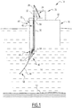
- Fig. 1 illustrates an installation 10 for producing fluids according to the invention.
- This installation 10 is for instance intended to collect a fluid, namely a hydrocarbon tapped at the bottom 12 of a body of water 14, and/or transfer said hydrocarbon to a transport vessel.
- the body of water 14 is for instance a lake, a sea, or an ocean.
- the depth of the body of water 14 perpendicular to the surface facility 16 is typically between 15 m and 3000 m.
- the hollow rigid tube 40 is a J-tube having a vertical straight upper part and a bent lower end.
- the hollow rigid tube 40 is a straight tube of the I-tube type.
- the curvature limiter 42 is moveable between a disengaged position, in which the retaining stop is not in direct contact with the stopper collar 48, and a safety-engaged position, in which the retaining stop is in direct contact with the stopper collar 48.
- the first ends 96 of the retaining lines 92 can be fixed to the holes 91 without distorting the retaining lines 92.
- the retaining apparatus is now connected to the stopper collar 48 placed around the connection 66 of the curvature limiter 42.
- the lower surface 78 of the cap further comprises a secondary ring 99 fixed to the lower surface 78.
- the secondary ring 99 is adapted to co-operate with the central ring 87 of the stopper collar 48 as an upper mechanical stop.
- the secondary ring 99 possesses the same width as the stopper collar 48.
Landscapes
- Engineering & Computer Science (AREA)
- Life Sciences & Earth Sciences (AREA)
- Geology (AREA)
- Mining & Mineral Resources (AREA)
- Physics & Mathematics (AREA)
- Environmental & Geological Engineering (AREA)
- Fluid Mechanics (AREA)
- General Life Sciences & Earth Sciences (AREA)
- Geochemistry & Mineralogy (AREA)
- Mechanical Engineering (AREA)
- Supports For Pipes And Cables (AREA)
Abstract
Description
- The present invention concerns an apparatus for mounting a flexible line onto a surface facility, comprising:
- a tube intended to be secured to said surface facility to receive the flexible line,
- a curvature limiter intended to be mounted around the flexible line, said curvature limiter being intended to be connected to the bottom of the tube, said curvature limiter defining a retaining stop, and
- a stopper collar able to co-operate with the retaining stop to retain the curvature limiter against the detachment of the curvature limiter from the tube.
- Such a mounting apparatus is used in particular in a hydrocarbon production installation on a body of water, for instance, a fixed rigid structure on the seabed, an oscillating structure secured to the seabed, or a floating structure, such as a surface naval base, a semisubmersible platform, a floating vertical column, or a vessel.
- The flexible line to be mounted on the structure is for instance a rising flexible pipe, also referred to as riser. Herein 'flexible pipes' are understood to mean those described in the standards published by the American Petroleum Institute (API), API 17J (4th Edition, May 2014) and API RP 17 B (5th Edition, May 2014), and well known to the person skilled in the art. More generally, the flexible line can be an integrated production bundle, an umbilical or an electrical cable.
- A mounting apparatus of the aforementioned type is used in particular when installing and connecting the flexible line to the surface structure.
- For this purpose, in order to reduce the risks of damaging the structure and the flexible line, it is known to immerse the flexible line into the body of water below the surface structure and to lift it up to the connecting area located on the surface structure by means of a hoist. Such a connection is referred to by the term 'pull-in'.
- The flexible line is guided over the structure by introducing the same through a hollow rigid tube integral with the structure and oriented vertically, which is a protective sleeve. The hollow tube is for instance of the 'I tube' or 'J tube' type, depending on its conformation.
- At the upper outlet of the tube, the flexible line is connected to the surface installation via a manifold.
- In order to avoid any deterioration of the flexible line, for example under the effect of water agitation likely to bring it into contact with the structure, it is known to engagedly mount around the flexible line a curvature limiter adapted to locally impose a radius of curvature greater than the minimum radius of curvature which may be adopted by the flexible line.
- Hereafter, curvature limiters are understood to both curvature limiters, composed e.g. of articulated rigid elements called 'vertebrae', and stiffeners, composed e.g. of plastic molded blocks, as well as combinations thereof.
- A stiffener is for instance arranged around the flexible line close to the upper end thereof, so as to co-operate with the hollow tube when the flexible line is inserted into the tube.
- For this purpose, at first, the stiffener and the flexible line are moved together to the lower end of the hollow tube until the stiffener has been partially inserted into the hollow tube. Next, in a second stage, the flexible line is moved upwards in relation to the stiffener for lifting the same up through the hollow tube in view of connecting it to the surface structure.
- During this second phase, the stiffener is maintained to be translationally immobile within the bottom extremity of the hollow tube through embedding and/or fastening by means of clamps.
- During this process the bend stiffener and portion of flexible pipe body are typically orientated in a vertical direction. If the bend stiffener is unsupported partially or wholly, due to an error during assembly the bend stiffener can plummet down the length of the pipe by virtue of gravitational force. This can be highly disruptive, as the bend stiffener is very heavy (typically more than 5000 kg, and even more than 10000 kg in some instances). This could also damage the flexible pipe, and/or the bend stiffener.
- In order to overcome such problems, an apparatus of the above-mentioned type is known from
US 8 955 593 B2 . In this apparatus, safety ropes are connected to the bell mouth at the lower end of the hollow tube and to a stopper collar secured on the bend stiffener. The ropes are able to prevent the fall of the bend stiffener in case the clamps fail. - Despite offering a solution to avoid the bend stiffener to drop unexpectedly by supporting it with safety ropes, this solution is however not entirely satisfactory. Indeed during the installation, the bell mouth and the bend stiffener need to be perfectly aligned so as to allow the safety ropes to remain vertical and approximately parallel to the tube. In reality, achieving this alignment necessitates adjustments of the bell mouth and the bend stiffener, often not straightforward given the movements of the structure resulting for example from waves and currents.
- One aim of the invention is to provide an apparatus which allows the easy and safe installation of a bend stiffener around a flexible line, with limited risk of damage to the stiffener and/or the line.
- For this purposes, the subject matter of the invention is an apparatus for mounting a flexible pipe onto a surface facility, in which the stopper collar is mounted rotatable around the curvature limiter.
- The apparatus according to the invention may comprise any or several of the following features, taken individually or according to any technically possible combination:
- the stopper collar is made of several parts assembled together;
- a retaining line to connect the stopper collar to the tube and/or to the surface facility;
- the stopper collar comprises a central ring mounted around the curvature limiter and at least one protruding arm, a first end of the retaining line being connected to said protruding arm;
- a plurality of retaining lines angularly distributed around a rotation axis of the stopper collar, each first end of a retaining line being connected to the protruding arm;
- the curvature limiter comprises a cap, said cap capable of being at least partially inserted into the tube, a bend stiffener, and a connection between the cap and the bend stiffener, the connection defining an annular groove located between said cap and said bend stiffener.
- the cap defines the retaining stop, the stopper collar being received in the annular groove;
- the curvature limiter is moveable between a disengaged position where the retaining stop is not in direct contact with the stopper collar, and a safety-engaged position where the retaining stop is in direct contact with the stopper collar.
- The present invention also concerns a method for mounting a flexible line onto a surface facility by means of an apparatus as defined above, characterised by the following steps:
- providing a tube secured to said surface facility,
- providing a curvature limiter mounted around the flexible line, connecting the curvature limiter to the bottom of the tube, said curvature limiter defining a retaining stop,
- mounting a stopper collar able to co-operate with the retaining stop to retain the curvature limiter against the detachment of the curvature limiter from the tube.
- The stopper collar is mounted rotatable around the curvature limiter.
- The method according to the invention may comprise one or several of the following features, taken individually or in any technically possible combination:
- connecting the stopper collar to the tube and/or to the surface facility by at least one retaining line;
- connecting the stopper collar to the surface facility comprises, in succession: hanging the retaining line from the surface facility without connecting it to the stopper collar, rotating the stopper collar around the curvature limiter to align the stopper collar with the retaining line, then connecting the retaining line to the stopper collar;
- the mounting of the stopper collar comprises mounting a central ring of the stopper collar around the curvature limiter, mounting at least one protruding arm protruding from the central ring, then connecting the retaining line to the protruding arm;
- the stopper collar is made of several parts, the mounting of the stopper collar including assembling the parts of the stopper collar around the curvature limiter before connecting the curvature limiter to the bottom of the tube;
- the curvature limiter comprises a cap, said cap capable of being at least partially inserted into the tube, a bend stiffener, and an annular groove located between said cap and said bend stiffener, the method comprising mounting of the stopper collar in the annular groove;
- after mounting the stopper collar onto the curvature limiter, putting the curvature limiter in a disengaged position where the retaining stop is not in direct contact with the stopper collar, and when the curvature limiter detaches from the tube, letting the stopper collar pass into a safety-engaged position where the retaining stop is in direct contact with the stopper collar.
- The invention will be better understood by reading the following description, provided only as way of example, and given with reference being made to the enclosed drawings, where:
-
Fig. 1 is a schematic view of an installation for extracting fluid according to the invention; -
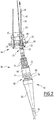
Fig. 2 illustrates the curvature limiter represented inFig. 1 before its attachment to the tube; -
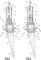
Fig. 3 is a view similar toFig. 2 illustrating the moment when the curvature limiter is attached to the tube; -
Fig. 4 is a view similar toFig. 3 illustrating the continued rising of the flexible pipe after the breaking of the frangible rods; -
Fig. 5 is a view similar toFig. 4 with the stopper collar being in the disengaged position; -
Fig. 6 is a view similar toFig. 5 with the stopper collar being in the safety-engaged position; -
Fig. 7 is a detailed view of the stopper collar; and -
Fig. 8 is a variant of the stopper collar according to the invention. -
Fig. 1 illustrates aninstallation 10 for producing fluids according to the invention. Thisinstallation 10 is for instance intended to collect a fluid, namely a hydrocarbon tapped at thebottom 12 of a body ofwater 14, and/or transfer said hydrocarbon to a transport vessel. - The
installation 10 comprises asurface facility 16 located at the surface of the body ofwater 14, at least aflexible line 18 to be connected to thesurface facility 16, and anapparatus 20 for mounting theflexible line 18 to thesurface facility 16. - The body of
water 14 is for instance a lake, a sea, or an ocean. The depth of the body ofwater 14 perpendicular to thesurface facility 16 is typically between 15 m and 3000 m. - The
surface facility 16 is for example a surface naval base, a semisubmersible platform, a floating vertical column, an offloading buoy or a vessel such as an FPSO (« Floating Production, Storage and Offloading), or a FLNG (« Floating Liquefied Natural Gas). - Alternatively,
surface facility 16 is a jacket-like fixed rigid structure or an oscillating structure secured downward of the sea, e.g. a TLP (« Tension Leg Platform »). - The
surface facility 16 has anupper surface 22, on which is mounted a hoist 24 for handling theflexible line 18 and a manifold 26 adapted for connecting one end of theflexible line 18. - The hoist 24 comprises a
cable 28, which can be deployed for pulling up theflexible line 18. - In the example represented in
Fig. 1 , theflexible line 18 is a fluid-carrying flexibletubular pipe 30 internally defining a fluid flow path. This pipe is also referred to as a rising pipe, or riser, and is to connect a wellhead (not shown) located at the bottom 12 of the body ofwater 14 to the manifold 26 located at theupper surface 22 of the floatingsurface facility 16. - Alternatively, the
flexible line 18 is for example an umbilical-like composite harness or 'integrated service umbilical' (ISU), well known by the person skilled in the art and described in the standards published by the American Petroleum Institute (API) API RP 17 B paragraph 4.3.4. Alternatively, the flexible line may be a harness of electrical cables. - The
pipe 30 has at theupper end 32 thereof ahead 33 for connecting the working line to thecable 28. - As illustrated in
Figs. 2 to 4 , thehead 33 comprises a connectingsleeve 34 fastened to theupper end 32 of thepipe 30, and aneyelet 35 for inserting the lower end of the working line to thecable 28, rotatably mounted on an upper part of thesleeve 34 around a travel axis X-X' ofline 18. - The
pipe 30 is typically unwound and immersed into the body ofwater 14 from a surface laying vessel and is stored at the bottom 12 of the body ofwater 14. Next, the end of pipe 30 (section not laid on the seabed) is abandoned at the bottom 12 via a drop cable. - The mounting
apparatus 20 comprises a hollowrigid tube 40 for guiding and protecting theflexible line 18, which is integral withsurface facility 16, alocal curvature limiter 42 ofline 18, engaged around theline 18, remote from theupper end 32, and anassembly 44 for fastening thecurvature limiter 42 to the lower end of the hollowrigid tube 40. - The mounting
apparatus 20 further comprises anaxial immobilisation mechanism 46 for axially immobilising theflexible line 18 in thecurvature limiter 42. - According to the invention, as shown in
Fig. 5 , the mountingapparatus 20 further comprises astopper collar 48 able to retain thecurvature limiter 42 against the detachment of saidcurvature limiter 42 from thetube 40, and a retainingapparatus 49 connecting thestopper collar 48 to thesurface facility 16. - In the example represented in
Fig. 1 , the hollowrigid tube 40 is a J-tube having a vertical straight upper part and a bent lower end. Alternatively, the hollowrigid tube 40 is a straight tube of the I-tube type. - The
tube 40 comprises a hollowvertical sleeve 50, integral with the floatingsurface facility 16, and alower end collar 52 located at thelower end 54 ofsleeve 50. -
Sleeve 50 defines a lower passageway opening into the body ofwater 14 atlower end 54 and opening at theupper end 56 thereof close to theupper surface 22 of thesurface facility 16, above the body ofwater 14. -
Lower end collar 52 is immersed into the body ofwater 14. It has a truncated shape converging upward.Lower end collar 52 flares out downwards to co-operate with thecurvature limiter 42 via thefastening assembly 44. - The
curvature limiter 42 comprises, from bottom to top inFigs. 2 ,3, and 4 , abend stiffener 62 and acap 64. Thecurvature limiter 42 further comprises aconnection 66 between thebend stiffener 62 and thecap 64, joining saidbend stiffener 62 to saidcap 64. - The
bend stiffener 62 is for instance moulded from plastic material, such as polyurethane. It has here a truncated shape converging downward. -
Bend stiffener 62 andcap 64 internally define a central lumen for the travel of theflexible line 18 defining the travel axis X-X' ofline 18 inside thecurvature limiter 42, coinciding with the longitudinal axis ofline 18. - As shown in
Figs. 2 to 4 , in thebend stiffener 62 and in thecap 64, the lumen has a cross-section substantially conjugate with the external cross-section ofline 18. - The
bend stiffener 62 andcap 64 thus locally enforce upon the flexible line 18 a radius of curvature which is greater than the minimum radius of curvature that theflexible line 18 allows. - As will be apparent below, the
curvature limiter 42 is moveable between a dismantled position represented inFigs. 1 and2 , in which it is placed remote from the hollowrigid tube 40, and a position mounted on the hollowrigid tube 40, represented inFigs. 3 et 4 , in which thecap 64 is fastened to thelower end collar 52 by means of thefastening assembly 44. - The
cap 64 is here bell-shaped. It comprises anupper surface 76 and alower surface 78. The cap further comprises afrustum 80 converging upwards from thelower surface 78. - The
upper surface 76 is connected to thehead 33 by theaxial immobilisation mechanism 46. In the example represented inFigs. 2 to 4 , theaxial immobilisation mechanism 46 comprises a plurality offrangible rods 81. - The
lower surface 78 defines a retaining stop. - The
frustum 80 is able to co-operate withlower end collar 52 to abut thecap 64 to thelower end collar 52. - The
bend stiffener 62 and thecap 64 are located at a vertical distance from each other. Theconnection 66 connects thebend stiffener 62 and thecap 64. It has a transverse extent smaller than the transverse extent of thebend stiffener 62 and of the cap 64.Theconnection 66 hence defines anannular groove 82 between thebend stiffener 62 and thecap 64. - In the example shown in
Fig. 2 to 4 , theconnection 66 is tubular. - The
fastening assembly 44 connects thecurvature limiter 42 to thetube 40. Thefastening assembly 44 is configured to engage on thelower surface 78 of thecap 64 to retain thecap 64 in displacement. This is the case in particular when thefrangible rods 81 are broken. This allows theflexible line 18 and thehead 33 to move axially relative to thecurvature limiter 42, thecurvature limiter 42 remaining fastened to the lower end oftube 40. - The
fastening assembly 44 for example comprisessupports 83, a locking apparatus (in this case locking pawls 84) andelastic elements 85. The supports 83, the locking pawls 84 and theelastic elements 85 are mounted on thetube 40. - The supports 83 are fastened securely to the
tube 40. The lockingpawls 84 are pivotally connected to thesupports 83 by means of spindles which are securely fastened to thesupports 83. The lower part of each lockingpawl 84 can pass inside slots in thelower end collar 52. - The
elastic elements 85 are disposed inside thesupports 83. Their function is to hold therespective locking pawl 84 in the locking position. - The locking
pawls 84 are able to co-operate with thelower surface 78 to prevent thecurvature limiter 42 from falling downwards. - In reference to
figure 7 , thestopper collar 48 comprises acentral ring 87 mounted around thecurvature limiter 42 and at least one protrudingarm 88, radially protruding from thecentral ring 87. - As illustrated in
Fig. 5 to 6 , thestopper collar 48 is mounted freely rotatable around a rotation axis X-X' around thecurvature limiter 42. In a preferred embodiment, thestopper collar 48 is received in theannular groove 82. It is able to abut against thelower surface 78 of the cap. - Coming back to
Fig. 7 , thestopper collar 48 comprises several circumferential segments assembled together by connectingparts 90. - The connecting
parts 90 comprise for example bolts and nuts. - The protruding
arms 88 radially protrude from thecentral ring 87. The protrudingarms 88 protrude generally radially to the axis X-X' from thecentral ring 87. - Each protruding
arm 88 comprises ahole 91 intended to receive the retaining lines 92. Thehole 91 preferably locates at the free end of the protrudingarm 88, away from thecentral ring 87. - In the example shown in
Fig. 7 , thestopper collar 48 comprises four protrudingarms 88. The number of protrudingarms 88 is more generally comprised between 1 and 6. - As illustrated in
Figs. 5 to 6 , after being mounted on thetube 40, thecurvature limiter 42 is moveable between a disengaged position, in which the retaining stop is not in direct contact with thestopper collar 48, and a safety-engaged position, in which the retaining stop is in direct contact with thestopper collar 48. - The retaining
apparatus 49 comprises at least a retainingline 92. It generally comprises at least a retainingline 92 for eachprotruding arm 88. - The retaining lines 92 are angularly distributed around the rotation axis X-X' of the
stopper collar 48. The number of the retaininglines 92 preferably equals the number of the protrudingarms 88. - Each of the retaining lines 92 comprises two ends. A first
lower end 96 is connected to the corresponding protrudingarm 88 of each retainingline 92. A second upper end 98 is connected to thetube 40 and/or to thesurface facility 16, preferably to a retaining structure located above the lower end of thetube 40. - A method for mounting the
flexible line 18 to thesurface facility 16 will now be described with reference toFigs. 2 to 6 . - Initially, when the
flexible line 18 is stored in a vessel or ashore, acurvature limiter 42 is engaged around theline 18, remote from theupper end 32 ofpipe 30. - For this purpose, the
line 18 is inserted into the lumen successively throughbend stiffener 62,connection 66, and thecap 64. Next, the connectinghead 33 is axially and angularly fastened toline 18, at theupper end 32 ofpipe 30. - With reference to
Fig. 2 , thefrangible rods 81 enable axial immobilisation of theflexible line 18 in the axial direction inside thecurvature limiter 42, namely when an upward pulling force is applied toline 18. Thereby, theaxial immobilisation mechanism 46 is activated. - As a next step, the
stopper collar 48 is installed around theannular groove 82 of thecurvature limiter 42. Thecentral ring 87 forming thestopper collar 48 are assembled together around theannular groove 82 and connected together to form an integral component by the connectingparts 90, for example with bolts and nuts. - The
stopper collar 48 is not shown on thefigures 2 ,3 and 4 . Theline 18 is then immersed into the body ofwater 14. Whenline 18 is to be connected to themanifold 26 of thesurface facility 16, the hoist 24 is activated for lowering thecable 28 through the hollowrigid tube 40, next connecting the lower end of thecable 28 to the connectinghead 33 located at theupper end 32 ofline 18.Line 18 and thecurvature limiter 42 are placed under thelower end collar 52 of the hollowrigid tube 40, away from thetube 40. - The hoist 24 is then activated for lifting the
cable 28 up to theupper end 56 of the hollowrigid tube 40. Lifting thecable 28 causes theline 18 to be moved together with thecurvature limiter 42 towards thelower end collar 52 up to the intermediate position represented inFig. 2 . - Next, in the vicinity of the
rigid tube 40 or when thecurvature limiter 42 is partially introduced into therigid tube 40, the hoist 24 is stopped. - The
stopper collar 48 is connected to the retaining structure oftube 40 which is located above the lower end of thetube 40. - Firstly, the second ends of retaining
lines 92 are connected to the retaining structure oftube 40. The first ends 96 of retaininglines 92 are disposed at approximately the same height, and are preferably angularly evenly distributed around therigid tube 40. The retaining lines 92 are then hung from thetube 40 with their first free ends located in the vicinity of the lower end of thetube 40 below thelower end collar 52. - Then, the first ends 96 of the retaining
lines 92 are attached to the protrudingarms 88 of thestopper collar 48, advantageously by a diver. Because thestopper collar 48 is freely rotatable around its rotation axis X-X', if the retaininglines 92 are not aligned to theholes 91, thestopper collar 48 is simply rotated around its rotation axis X-X' to achieve the alignment without additional measures. - Once the
holes 91 on each protrudingarms 88 are aligned withrespective retaining lines 92, the first ends 96 of the retaininglines 92 can be fixed to theholes 91 without distorting the retaining lines 92. - The retaining apparatus is now connected to the
stopper collar 48 placed around theconnection 66 of thecurvature limiter 42. - The diver leaves the vicinity of the
curvature limiter 42 for safety. - The hoist 24 is then activated for lifting the
cable 28, and the introduction of thecap 64 into thelower end collar 52 continues, until thelower surface 78 comes into contact with the lockingpawls 84, as represented inFig. 3 . - With the raising operation continuing, the locking
claws 84 are first pushed away from the rotation axis X-X', which causes the lockingpawls 84 to pivot about the spindles. - As soon as the
lower surface 78 projects beyond theclaws 84, theclaws 84 are forced by theelastic elements 85 to rotate towards the rotation axis X-X'. When this movement has been completed, thecurvature limiter 42 is locked. The co-operation between thefrustum 80 and thelower end collar 52 prevents thecurvature limiter 42 from rising and, moreover, the lockingclaws 84 prevent thecurvature limiter 42 from descending. - The
fastening assembly 44 thus immobilises thecurvature limiter 42 axially in relation to thehollow tube 40. - In this position, the
stopper collar 48 is in a disengaged position with respect to thecurvature limiter 42. Thestopper collar 48 locates at a distance from the retaining stop at thelower surface 78 of thecap 64. - Then, the
axial immobilisation mechanism 46 is released to allow theline 18 to be lifted up through thecurvature limiter 42 andtube 40. In the example illustrated inFig. 4 , thefrangible rods 81 are broken, which enables theline 18 to be lifted through thecurvature limiter 42 andtube 40, thecurvature limiter 42 remaining immobilised inside thetube 40. - For this purpose, the hoist 24 is activated to move the connecting
head 33 in the axial direction. - The pulling force necessary to break the
frangible rods 81 for axially releasing theline 18 in relation tocurvature limiter 42 is much lower than the axial strength of thepipe 30 so that there is no risk of over stressing and damaging theline 18 during this step. - With reference to
Fig. 3 , theline 18 is then lifted up through the central lumen of thecurvature limiter 42 and through the interior of thetube 40, up to the manifold 26, thecurvature limiter 42 remaining immobile in relation totube 40.Line 18 is then connected to themanifold 26. - As shown in
Fig. 5 , during the lifting ofline 18, thecurvature limiter 42 is in most cases immobilised in relation to thetube 40 through thefastening assembly 44. In the unlikely event of an uncomplete engagement into the fastening assembly or/and of the failure of thefastening assembly 44, represented inFig. 6 , thecurvature limiter 42 detaches from thetube 40 and falls under the effect of gravity. - In this case, the
stopper collar 48 comes into direct contact with the retaining stop, reaching a safety-engaged position. The retaining lines 92, being active to retain thestopper collar 48 through the protrudingarms 88, thestopper collar 48 co-operates with the retaining stop to retain thecurvature limiter 42. This prevents the further drop of thecurvature limiter 42. - In the event of the failure of
fastening assembly 44 between thecurvature limiter 42 and thetube 40, thestopper collar 48 is particularly efficient to retain thecurvature limiter 42 in place, which prevents damages to both the external sheath of theflexible line 18 and to thebend stiffener 62. - The
stopper collar 48 being able to rotate freely around the tube, the retaininglines 92 are able to run approximately in parallel totube 40 without twisting. This is especially beneficial during the installation where no additional alignment of the stopper collar and the tube is required. The apparatus according to the invention is therefore particularly simple to assemble. - In addition, the stopper collar is relatively light and cheap to produce, incurring less cost.
- In a variant as shown in
Fig. 8 , thelower surface 78 of the cap further comprises asecondary ring 99 fixed to thelower surface 78. Thesecondary ring 99 is adapted to co-operate with thecentral ring 87 of thestopper collar 48 as an upper mechanical stop. Preferably, thesecondary ring 99 possesses the same width as thestopper collar 48. - In a variant, a monitoring system is coupled to the
apparatus 20 to oversee its change. The monitoring system can comprise a sensor measuring the relative displacement between thecurvature limiter 42 and thestopper collar 48 after the former is connected to thetube 40. The sensor could emit signals when thecurvature limiter 42 starts slipping out of thetube 40.
Claims (15)
- Apparatus (20) for mounting a flexible line (18) onto a surface facility (16), comprising:- a tube (40) intended to be secured to said surface facility (16) to receive the flexible line (18),- a curvature limiter (42) intended to be mounted around the flexible line (18), said curvature limiter (42) being intended to be connected to the bottom of the tube (40), said curvature limiter (42) defining a retaining stop, and- a stopper collar (48) able to co-operate with the retaining stop to retain the curvature limiter (42) against the detachment of the curvature limiter (42) from the tube (40),characterised in that the stopper collar (48) is mounted rotatable around the curvature limiter (42).
- Apparatus (20) according to claim 1, wherein the stopper collar (48) is made of several parts assembled together.
- Apparatus (20) according to claim 1 or 2, comprising at least a retaining line (92) to connect the stopper collar (48) to the tube (40) and/or to the surface facility (16).
- Apparatus (20) according to claim 3, wherein the stopper collar (48) comprises a central ring (87) mounted around the curvature limiter (42) and at least one protruding arm (88), a first end (96) of the retaining line (92) being connected to said protruding arm (88).
- Apparatus (20) according to claim 4, comprising a plurality of retaining lines (92) angularly distributed around a rotation axis of the stopper collar (48), each first end (96) of a retaining line being connected to the protruding arm (88).
- Apparatus (20) according to any one of the preceding claims, wherein the curvature limiter (42) comprises:- a cap (64), said cap (64) capable of being at least partially inserted into the tube (40),- a bend stiffener (62), and- a connection (66) between the cap (64) and the bend stiffener (62), the connection (66) defining an annular groove (82) located between said cap (64) and said bend stiffener (62).
- Apparatus (20) according to claim 6, wherein the cap (64) defines the retaining stop, the stopper collar (48) being received in the annular groove (82).
- Apparatus (20) according to any one of the preceding claims, wherein the curvature limiter (42) is moveable between:- a disengaged position where the retaining stop is not in direct contact with the stopper collar (48), and- a safety-engaged position where the retaining stop is in direct contact with the stopper collar (48).
- A method for mounting a flexible line (18) onto a surface facility (16), comprising the steps of- providing a tube (40) secured to said surface facility (16),- providing a curvature limiter (42) mounted around the flexible line (18), connecting the curvature limiter (42) to the bottom of the tube (40), said curvature limiter (42) defining a retaining stop, and- mounting a stopper collar (48) able to co-operate with the retaining stop to retain the curvature limiter (42) against the detachment of the curvature limiter (42) from the tube (40),characterised in that the stopper collar (48) is mounted rotatable around the curvature limiter (42).
- The method according to claim 9, comprising connecting the stopper collar (48) to the tube (40) and/or to the surface facility (16) by at least one retaining line (92).
- The method according to claim 10, wherein connecting the stopper collar (48) to the surface facility (16) comprises, in succession:- hanging the retaining line (92) from the surface facility (16) without connecting it to the stopper collar (48),- rotating the stopper collar (48) around the curvature limiter (42) to align the stopper collar (48) with the retaining line (92), then- connecting the retaining line (92) to the stopper collar (48).
- The method according to claim 11, wherein the mounting of the stopper collar (48) comprises mounting a central ring (87) of the stopper collar (48) around the curvature limiter (42), mounting at least one protruding arm (88) protruding from the central ring (87), then connecting the retaining line (92) to the protruding arm (88).
- The method according to any one of claims 9 to 12, wherein the stopper collar (48) is made of several parts, the mounting of the stopper collar (48) including assembling the parts of the stopper collar (48) around the curvature limiter (42) before connecting the curvature limiter (42) to the bottom of the tube (40).
- The method according to any one of claims 9 to 13, wherein the curvature limiter (42) comprises:- a cap (64), said cap (64) capable of being at least partially inserted into the tube (40),- a bend stiffener (62), and- an annular groove (82) located between said cap (64) and said bend stiffener (62),the method comprising mounting of the stopper collar (48) in the annular groove (82).
- A method according to any one of the claims 9 to 14 comprising, after mounting the stopper collar (48) onto the curvature limiter (42), putting the curvature limiter (42) in a disengaged position where the retaining stop is not in direct contact with the stopper collar (48), and when the curvature limiter (42) detaches from the tube (40), letting the stopper collar (48) pass into a safety-engaged position where the retaining stop is in direct contact with the stopper collar (48).
Priority Applications (2)
| Application Number | Priority Date | Filing Date | Title |
|---|---|---|---|
| EP17306410.6A EP3473801A1 (en) | 2017-10-18 | 2017-10-18 | Apparatus for mounting a flexible line onto a surface facility and related method |
| PCT/EP2018/078597 WO2019077058A1 (en) | 2017-10-18 | 2018-10-18 | Apparatus for mounting a flexible line onto a surface facility and related method |
Applications Claiming Priority (1)
| Application Number | Priority Date | Filing Date | Title |
|---|---|---|---|
| EP17306410.6A EP3473801A1 (en) | 2017-10-18 | 2017-10-18 | Apparatus for mounting a flexible line onto a surface facility and related method |
Publications (1)
| Publication Number | Publication Date |
|---|---|
| EP3473801A1 true EP3473801A1 (en) | 2019-04-24 |
Family
ID=60191301
Family Applications (1)
| Application Number | Title | Priority Date | Filing Date |
|---|---|---|---|
| EP17306410.6A Withdrawn EP3473801A1 (en) | 2017-10-18 | 2017-10-18 | Apparatus for mounting a flexible line onto a surface facility and related method |
Country Status (2)
| Country | Link |
|---|---|
| EP (1) | EP3473801A1 (en) |
| WO (1) | WO2019077058A1 (en) |
Cited By (7)
| Publication number | Priority date | Publication date | Assignee | Title |
|---|---|---|---|---|
| WO2021048592A1 (en) * | 2019-09-09 | 2021-03-18 | Saipem S.P.A. | Off shore riser fixation system and method |
| WO2022120446A1 (en) * | 2020-12-11 | 2022-06-16 | Petróleo Brasileiro S.A. - Petrobras | Adapter tool for coupling a bend stiffener with a diverless bellmouth interface in a bsn900e bellmouth and assembly method |
| US11613934B2 (en) * | 2018-06-06 | 2023-03-28 | Petroleo Brasileiro S.A.—Petrobras | System for coupling between a bend stiffener and a bell mouth comprising a plurality of locking mechanisms |
| WO2024121575A1 (en) * | 2022-12-09 | 2024-06-13 | S3N Ventus Ltd | A connector assembly for emergency decoupling of a subsea end fitting of a movable subsea structure |
| WO2024121572A1 (en) * | 2022-12-09 | 2024-06-13 | S3N Ventus Ltd | A hang-off device for an end fitting of a subsea tubular |
| WO2024184633A1 (en) * | 2023-03-09 | 2024-09-12 | BMS Design Limited | Connector assembly |
| US12345099B2 (en) | 2022-05-30 | 2025-07-01 | Petróleo Brasileiro S.A.—Petrobras | Compliant component for supporting bend stiffeners |
Citations (5)
| Publication number | Priority date | Publication date | Assignee | Title |
|---|---|---|---|---|
| GB2203508A (en) * | 1987-04-16 | 1988-10-19 | Shell Int Research | System and method for securing a marine riser to a floating structure |
| GB2411445A (en) * | 2004-02-27 | 2005-08-31 | Crp Group Ltd | Attachment for bend stiffener |
| US20110162747A1 (en) * | 2008-05-30 | 2011-07-07 | Sylvain Routeau | Device for mounting a flexible line on a structure, and related installation and method |
| US20140212221A1 (en) * | 2011-09-07 | 2014-07-31 | Technip France | Method for connecting a flexible line to a structure of a fluid exploitation installation and associated connection device |
| US8955593B2 (en) | 2011-12-29 | 2015-02-17 | Petroleo Brasileiro S.A.-Petrobras | Damping sleeve and anchoring method |
-
2017
- 2017-10-18 EP EP17306410.6A patent/EP3473801A1/en not_active Withdrawn
-
2018
- 2018-10-18 WO PCT/EP2018/078597 patent/WO2019077058A1/en not_active Ceased
Patent Citations (5)
| Publication number | Priority date | Publication date | Assignee | Title |
|---|---|---|---|---|
| GB2203508A (en) * | 1987-04-16 | 1988-10-19 | Shell Int Research | System and method for securing a marine riser to a floating structure |
| GB2411445A (en) * | 2004-02-27 | 2005-08-31 | Crp Group Ltd | Attachment for bend stiffener |
| US20110162747A1 (en) * | 2008-05-30 | 2011-07-07 | Sylvain Routeau | Device for mounting a flexible line on a structure, and related installation and method |
| US20140212221A1 (en) * | 2011-09-07 | 2014-07-31 | Technip France | Method for connecting a flexible line to a structure of a fluid exploitation installation and associated connection device |
| US8955593B2 (en) | 2011-12-29 | 2015-02-17 | Petroleo Brasileiro S.A.-Petrobras | Damping sleeve and anchoring method |
Non-Patent Citations (2)
| Title |
|---|
| "API 17J", May 2014, AMERICAN PETROLEUM INSTITUTE (API |
| "API RP 17 B", May 2014 |
Cited By (11)
| Publication number | Priority date | Publication date | Assignee | Title |
|---|---|---|---|---|
| US11613934B2 (en) * | 2018-06-06 | 2023-03-28 | Petroleo Brasileiro S.A.—Petrobras | System for coupling between a bend stiffener and a bell mouth comprising a plurality of locking mechanisms |
| WO2021048592A1 (en) * | 2019-09-09 | 2021-03-18 | Saipem S.P.A. | Off shore riser fixation system and method |
| US11773661B2 (en) | 2019-09-09 | 2023-10-03 | Saipem S.P.A. | Off shore riser fixation system and method |
| WO2022120446A1 (en) * | 2020-12-11 | 2022-06-16 | Petróleo Brasileiro S.A. - Petrobras | Adapter tool for coupling a bend stiffener with a diverless bellmouth interface in a bsn900e bellmouth and assembly method |
| CN116940742A (en) * | 2020-12-11 | 2023-10-24 | 巴西石油公司 | Adapter tool for coupling a bend stiffener with a submersible flare interface in a BSN900E flare and method of assembly |
| US12129719B2 (en) | 2020-12-11 | 2024-10-29 | Petróleo Brasileiro S.A.—Petrobras | Adapter tool for coupling a bend stiffener with diverless bell mouth interface (DLBM) into a BSN900E bell mouth and assembly method |
| US12345099B2 (en) | 2022-05-30 | 2025-07-01 | Petróleo Brasileiro S.A.—Petrobras | Compliant component for supporting bend stiffeners |
| WO2024121575A1 (en) * | 2022-12-09 | 2024-06-13 | S3N Ventus Ltd | A connector assembly for emergency decoupling of a subsea end fitting of a movable subsea structure |
| WO2024121572A1 (en) * | 2022-12-09 | 2024-06-13 | S3N Ventus Ltd | A hang-off device for an end fitting of a subsea tubular |
| GB2625270A (en) * | 2022-12-09 | 2024-06-19 | S3N Ventus Ltd | A hang-off device for an end fitting of a subsea tubular |
| WO2024184633A1 (en) * | 2023-03-09 | 2024-09-12 | BMS Design Limited | Connector assembly |
Also Published As
| Publication number | Publication date |
|---|---|
| WO2019077058A1 (en) | 2019-04-25 |
Similar Documents
| Publication | Publication Date | Title |
|---|---|---|
| WO2019077058A1 (en) | Apparatus for mounting a flexible line onto a surface facility and related method | |
| EP0251488B1 (en) | Flexible riser system and method for installing the same | |
| US8596912B2 (en) | Device for mounting a flexible line on a structure, and related installation and method | |
| EP2524162B1 (en) | Improvements relating to abandonment and recovery of pipelines | |
| US20180258711A1 (en) | Steel catenary riser top interface | |
| EP4028627B1 (en) | Off shore riser fixation system and method | |
| US20140212221A1 (en) | Method for connecting a flexible line to a structure of a fluid exploitation installation and associated connection device | |
| US9476521B2 (en) | Method for laying a submarine line on the seabed | |
| CA2931158C (en) | Offshore flexible line installation and removal | |
| WO2011099869A2 (en) | A method of installing a flexible, elongate element | |
| AU2018296421B2 (en) | Offloading hydrocarbons from subsea fields | |
| EP2799660B1 (en) | Damping sleeve and anchoring method | |
| AU2022204243A1 (en) | Direct tie-in method | |
| BR112021002657A2 (en) | maneuvering loads in subsea operations | |
| EP3154852B1 (en) | A tensile overload protection system for offloading systems | |
| EP2778041A1 (en) | Assembly for transferring fluids between a vessel and a turret structure mounted in said vessel | |
| BR112016025690B1 (en) | METHOD OF CONNECTING A BOTTOM DUCT AND AN ASCENDING DUCT, AND INSTALLATION OF CONNECTION CONFIGURED TO CONNECT A BOTTOM DUCT WITH AN UPPER DUCT | |
| BR112022004202B1 (en) | SYSTEM AND METHOD FOR FIXING MARINE RISERS | |
| NO20171092A1 (en) | Offloading hydrocarbons from subsea fields | |
| NO338921B1 (en) | Underwater anchorage with flexible risers |
Legal Events
| Date | Code | Title | Description |
|---|---|---|---|
| PUAI | Public reference made under article 153(3) epc to a published international application that has entered the european phase |
Free format text: ORIGINAL CODE: 0009012 |
|
| STAA | Information on the status of an ep patent application or granted ep patent |
Free format text: STATUS: THE APPLICATION HAS BEEN PUBLISHED |
|
| AK | Designated contracting states |
Kind code of ref document: A1 Designated state(s): AL AT BE BG CH CY CZ DE DK EE ES FI FR GB GR HR HU IE IS IT LI LT LU LV MC MK MT NL NO PL PT RO RS SE SI SK SM TR |
|
| AX | Request for extension of the european patent |
Extension state: BA ME |
|
| STAA | Information on the status of an ep patent application or granted ep patent |
Free format text: STATUS: REQUEST FOR EXAMINATION WAS MADE |
|
| 17P | Request for examination filed |
Effective date: 20191003 |
|
| RBV | Designated contracting states (corrected) |
Designated state(s): AL AT BE BG CH CY CZ DE DK EE ES FI FR GB GR HR HU IE IS IT LI LT LU LV MC MK MT NL NO PL PT RO RS SE SI SK SM TR |
|
| GRAP | Despatch of communication of intention to grant a patent |
Free format text: ORIGINAL CODE: EPIDOSNIGR1 |
|
| STAA | Information on the status of an ep patent application or granted ep patent |
Free format text: STATUS: GRANT OF PATENT IS INTENDED |
|
| INTG | Intention to grant announced |
Effective date: 20200225 |
|
| RIN1 | Information on inventor provided before grant (corrected) |
Inventor name: LEITAO GONCALVES TOSTE, FERNANDO Inventor name: BOTTINO DI GIOIA ALMEIDA, HUGO Inventor name: RONALDO ANDRADE DOS REIS, CARLOS Inventor name: LARANJEIRA MOURA FARIAS, LIVIA |
|
| GRAJ | Information related to disapproval of communication of intention to grant by the applicant or resumption of examination proceedings by the epo deleted |
Free format text: ORIGINAL CODE: EPIDOSDIGR1 |
|
| GRAP | Despatch of communication of intention to grant a patent |
Free format text: ORIGINAL CODE: EPIDOSNIGR1 |
|
| INTG | Intention to grant announced |
Effective date: 20200729 |
|
| STAA | Information on the status of an ep patent application or granted ep patent |
Free format text: STATUS: THE APPLICATION IS DEEMED TO BE WITHDRAWN |
|
| 18D | Application deemed to be withdrawn |
Effective date: 20201209 |