EP2524162B1 - Improvements relating to abandonment and recovery of pipelines - Google Patents
Improvements relating to abandonment and recovery of pipelines Download PDFInfo
- Publication number
- EP2524162B1 EP2524162B1 EP11701545.3A EP11701545A EP2524162B1 EP 2524162 B1 EP2524162 B1 EP 2524162B1 EP 11701545 A EP11701545 A EP 11701545A EP 2524162 B1 EP2524162 B1 EP 2524162B1
- Authority
- EP
- European Patent Office
- Prior art keywords
- sling
- section
- sleeve
- piece
- pieces
- Prior art date
- Legal status (The legal status is an assumption and is not a legal conclusion. Google has not performed a legal analysis and makes no representation as to the accuracy of the status listed.)
- Active
Links
- 238000011084 recovery Methods 0.000 title claims description 15
- 238000000034 method Methods 0.000 claims description 28
- XLYOFNOQVPJJNP-UHFFFAOYSA-N water Substances O XLYOFNOQVPJJNP-UHFFFAOYSA-N 0.000 claims description 11
- 230000015572 biosynthetic process Effects 0.000 claims description 10
- 238000005755 formation reaction Methods 0.000 claims description 10
- 230000000295 complement effect Effects 0.000 claims description 9
- 238000005452 bending Methods 0.000 claims description 2
- 238000003860 storage Methods 0.000 description 5
- 241000282472 Canis lupus familiaris Species 0.000 description 4
- 230000008901 benefit Effects 0.000 description 3
- 239000002131 composite material Substances 0.000 description 3
- 230000015556 catabolic process Effects 0.000 description 2
- 239000000835 fiber Substances 0.000 description 2
- 230000004048 modification Effects 0.000 description 2
- 238000012986 modification Methods 0.000 description 2
- 239000004576 sand Substances 0.000 description 2
- 238000003466 welding Methods 0.000 description 2
- 229920000271 Kevlar® Polymers 0.000 description 1
- 229910000831 Steel Inorganic materials 0.000 description 1
- RTAQQCXQSZGOHL-UHFFFAOYSA-N Titanium Chemical compound [Ti] RTAQQCXQSZGOHL-UHFFFAOYSA-N 0.000 description 1
- 229920010741 Ultra High Molecular Weight Polyethylene (UHMWPE) Polymers 0.000 description 1
- 238000005299 abrasion Methods 0.000 description 1
- 239000003082 abrasive agent Substances 0.000 description 1
- 230000009471 action Effects 0.000 description 1
- 239000004760 aramid Substances 0.000 description 1
- 229920003235 aromatic polyamide Polymers 0.000 description 1
- 230000004888 barrier function Effects 0.000 description 1
- 230000009286 beneficial effect Effects 0.000 description 1
- 230000008602 contraction Effects 0.000 description 1
- 230000008878 coupling Effects 0.000 description 1
- 238000010168 coupling process Methods 0.000 description 1
- 238000005859 coupling reaction Methods 0.000 description 1
- 238000006731 degradation reaction Methods 0.000 description 1
- 230000002542 deteriorative effect Effects 0.000 description 1
- 230000000694 effects Effects 0.000 description 1
- 230000005489 elastic deformation Effects 0.000 description 1
- 238000005516 engineering process Methods 0.000 description 1
- 238000001914 filtration Methods 0.000 description 1
- 238000007667 floating Methods 0.000 description 1
- 229920001903 high density polyethylene Polymers 0.000 description 1
- 239000004700 high-density polyethylene Substances 0.000 description 1
- 239000004761 kevlar Substances 0.000 description 1
- 238000004519 manufacturing process Methods 0.000 description 1
- 239000000463 material Substances 0.000 description 1
- 239000011159 matrix material Substances 0.000 description 1
- 230000007935 neutral effect Effects 0.000 description 1
- 239000011295 pitch Substances 0.000 description 1
- 229920000642 polymer Polymers 0.000 description 1
- 230000008569 process Effects 0.000 description 1
- 230000001681 protective effect Effects 0.000 description 1
- 230000004044 response Effects 0.000 description 1
- 230000000284 resting effect Effects 0.000 description 1
- 238000007789 sealing Methods 0.000 description 1
- 229910001220 stainless steel Inorganic materials 0.000 description 1
- 239000010935 stainless steel Substances 0.000 description 1
- 239000010959 steel Substances 0.000 description 1
- 229920002994 synthetic fiber Polymers 0.000 description 1
- 229920001059 synthetic polymer Polymers 0.000 description 1
- 229910052719 titanium Inorganic materials 0.000 description 1
- 239000010936 titanium Substances 0.000 description 1
- 229920000785 ultra high molecular weight polyethylene Polymers 0.000 description 1
- 238000005303 weighing Methods 0.000 description 1
Images


Classifications
-
- F—MECHANICAL ENGINEERING; LIGHTING; HEATING; WEAPONS; BLASTING
- F16—ENGINEERING ELEMENTS AND UNITS; GENERAL MEASURES FOR PRODUCING AND MAINTAINING EFFECTIVE FUNCTIONING OF MACHINES OR INSTALLATIONS; THERMAL INSULATION IN GENERAL
- F16L—PIPES; JOINTS OR FITTINGS FOR PIPES; SUPPORTS FOR PIPES, CABLES OR PROTECTIVE TUBING; MEANS FOR THERMAL INSULATION IN GENERAL
- F16L1/00—Laying or reclaiming pipes; Repairing or joining pipes on or under water
- F16L1/12—Laying or reclaiming pipes on or under water
- F16L1/16—Laying or reclaiming pipes on or under water on the bottom
- F16L1/18—Laying or reclaiming pipes on or under water on the bottom the pipes being S- or J-shaped and under tension during laying
- F16L1/19—Laying or reclaiming pipes on or under water on the bottom the pipes being S- or J-shaped and under tension during laying the pipes being J-shaped
-
- F—MECHANICAL ENGINEERING; LIGHTING; HEATING; WEAPONS; BLASTING
- F16—ENGINEERING ELEMENTS AND UNITS; GENERAL MEASURES FOR PRODUCING AND MAINTAINING EFFECTIVE FUNCTIONING OF MACHINES OR INSTALLATIONS; THERMAL INSULATION IN GENERAL
- F16L—PIPES; JOINTS OR FITTINGS FOR PIPES; SUPPORTS FOR PIPES, CABLES OR PROTECTIVE TUBING; MEANS FOR THERMAL INSULATION IN GENERAL
- F16L1/00—Laying or reclaiming pipes; Repairing or joining pipes on or under water
- F16L1/12—Laying or reclaiming pipes on or under water
- F16L1/16—Laying or reclaiming pipes on or under water on the bottom
- F16L1/166—Reclaiming pipes
-
- F—MECHANICAL ENGINEERING; LIGHTING; HEATING; WEAPONS; BLASTING
- F16—ENGINEERING ELEMENTS AND UNITS; GENERAL MEASURES FOR PRODUCING AND MAINTAINING EFFECTIVE FUNCTIONING OF MACHINES OR INSTALLATIONS; THERMAL INSULATION IN GENERAL
- F16L—PIPES; JOINTS OR FITTINGS FOR PIPES; SUPPORTS FOR PIPES, CABLES OR PROTECTIVE TUBING; MEANS FOR THERMAL INSULATION IN GENERAL
- F16L1/00—Laying or reclaiming pipes; Repairing or joining pipes on or under water
- F16L1/12—Laying or reclaiming pipes on or under water
- F16L1/20—Accessories therefor, e.g. floats, weights
- F16L1/202—Accessories therefor, e.g. floats, weights fixed on or to vessels
- F16L1/207—Pipe handling apparatus
-
- F—MECHANICAL ENGINEERING; LIGHTING; HEATING; WEAPONS; BLASTING
- F16—ENGINEERING ELEMENTS AND UNITS; GENERAL MEASURES FOR PRODUCING AND MAINTAINING EFFECTIVE FUNCTIONING OF MACHINES OR INSTALLATIONS; THERMAL INSULATION IN GENERAL
- F16L—PIPES; JOINTS OR FITTINGS FOR PIPES; SUPPORTS FOR PIPES, CABLES OR PROTECTIVE TUBING; MEANS FOR THERMAL INSULATION IN GENERAL
- F16L1/00—Laying or reclaiming pipes; Repairing or joining pipes on or under water
- F16L1/26—Repairing or joining pipes on or under water
Definitions
- This invention relates to abandonment and recovery or 'A&R' procedures used in marine pipelaying, in which a floating vessel such as a barge is used to lay an offshore pipeline.
- the invention has particularly advantages when used with J-lay pipelaying equipment and it will be described in that context, but it is not necessarily limited to J-lay applications.
- the J-lay technique is suitable for pipelaying in deep water. It involves welding together successive pipe sections or 'joints' in an upright orientation in a J-lay tower on a pipelaying vessel. The resulting pipe string is launched downwardly into the water as it is formed. The pipe string adopts a single bend as it nears the seabed to lend a J-shape to the pipe string extending between the vessel and the seabed - hence 'J-lay'.
- J-lay is necessary in deep water because the pipe string with attached accessories extending from the pipelaying vessel to the seabed is extremely heavy, typically weighing hundreds of tonnes. To avoid buckling, the pipe string must bear that weight in tension, suspended from a holding device on the J-lay tower.
- the J-lay tower 10 of the barge 12 is supplied with double joints 14 of pipe made onshore, which are stored horizontally on the deck 16.
- the double joints 14 are lifted successively in horizontal orientation from the deck 16 to a tower entry level 18 using a pipe elevator system 20 best shown in Figure 2 .
- a double joint 14 is loaded into a pivoting erector arm 22, which upends the double joint 14 into an upright orientation and passes it over to a tower handling system comprising a tensioner 24.
- the double joint 14 is then lowered and aligned with the pipeline end held in a support bushing at a work station 26 on the tower 10.
- the double joint 14 is welded to the pipeline end at the work station 26 before the load of the pipe string is transferred from the support bushing to the tensioner 24 near the top of the J-lay tower 10.
- the completed pipe string is then lowered down to the support bushing for the addition of the next double joint 14.
- the tensioner 24 and the support bushing alternate to grip the pipeline end, interacting in a so-called 'hand-overhand' manner.
- 'Abandonment and recovery' refers to the procedures of laying down and retrieving a pipeline end from the seabed. Those procedures are necessary during normal pipelaying start-up and termination. They are also necessary whenever pipelaying must be interrupted and resumed. For example, the pipelaying vessel may suffer a critical breakdown. More commonly, pipelaying is interrupted due to deteriorating weather conditions, which may stress the pipeline and reduce its fatigue life as the pipelaying vessel rolls and pitches in a rough sea or if it has difficulty remaining in position due to winds and currents. In such cases, the pipelaying vessel may need to abandon the pipeline end and leave the work area. When the problem that caused abandonment has passed, the vessel will return later to recover the pipeline end and resume pipelaying.
- Abandonment involves attaching a cap to the pipeline end, typically a pipeline end terminal or 'PLET'.
- a shackle is attached to a hook on the PLET to secure a wire running through a winch on the pipelaying vessel, and tension is transferred from the tensioner of the J-lay tower to the winch.
- the winch then lowers the PLET into the sea until the pipeline and PLET rest on the seabed.
- the wire is then detached from the hook of the PLET, for example using a remote-controlled linkage or an ROV, and is retracted by the vessel for storage.
- a recovery buoy is attached to the PLET during abandonment, enabling the PLET and the pipeline end to be located and retrieved during a subsequent recovery procedure.
- the recovery procedure is the reverse of abandonment as the wire is reattached to the PLET, typically using an ROV, and the PLET with the attached pipeline end is winched back up to the pipelaying vessel for pipelaying to resume.
- the pipelaying vessel may remain on station above the abandoned pipeline, for example while riding out a period of bad weather.
- the wire may be kept attached to the PLET resting on the seabed until the bad weather has passed. This eases the recovery procedure considerably.
- Traction (capstan) winches are generally used in A&R procedures to handle the high top tensions characteristic of deep-water pipelaying.
- Such winches require a continuous length of wire, generally of steel. That wire must be of large diameter - typically 70 mm to 120 mm - to support the great weight of the pipe string that extends above the seabed as the pipeline end nears the surface. Obviously, the wire must also be very long: generally several thousand metres long. Consequently, the wire itself may weigh in excess of 300 tonnes, and it takes up a great deal of space on the vessel when not in use. It also requires a large, powerful and hence expensive winch.
- A&R wires remain a high-cost item. They are also susceptible to damage, particularly in the corrosive marine environment, and so have a limited life. If damaged, the whole wire may have to be down-rated or rejected; this makes it advisable for the pipelaying vessel to carry a spare wire but this, of course, doubles the problems of high cost and storage space.
- the larger-capacity wire and winch may be used to lower the pipeline end to an intermediate depth at which the top tension reduces to an extent that the load can be transferred to the smaller-capacity wire and winch.
- the higher-capacity wire can then be disconnected from the pipeline end and retracted to the pipelaying vessel.
- the smaller-capacity wire and winch then takes over to lower the pipeline end the rest of the way to the seabed. This means that a shorter length of larger-diameter wire is required on the drum of the higher-capacity winch, reducing space requirements and potentially also cost.
- each wire remains vulnerable to damage and if spares are kept on board for both wires, the pipelaying vessel must accommodate four wires and not just two. This consumes space and reduces any cost advantage.
- US 2003/0099A15 A1 or WO 2005/005874 A1 discloses a method of abandoning a pipeline during subsea pipelaying using a plurality of sling sections.
- the invention resides in a sling section cooperable with like sling sections to form a sling for use in abandonment or recovery of a pipeline, the sling section being elongate to define opposed ends, and comprising: a first end-piece at one end of the sling section; and a second end-piece at the opposite end of the sling section.
- the sling section further comprises: complementary connector formations associated with each respective end-piece, each connector formation being cooperable, in use when forming a sling, with a complementary connector formation of a neighbouring like sling section in the sling; a tensile load-bearing sling element extending between the end-pieces; and a sleeve around the sling element.
- the sling section is capable of being handled by pipe-joint handling apparatus associated with a J-lay tower.
- the sleeve is more resistant to bending than the sling element, and is preferably torsionally stiffer than the sling element.
- the sleeve suitably extends between, and is supported by, the end-pieces.
- the sleeve is movable longitudinally with respect to at least one of the end-pieces to accommodate extension or contraction of the sling element in use.
- the sleeve is spaced from the sling element.
- the sling section preferably comprises a port for admitting water to the space between the sleeve and the sling element when the sling section is submerged in use.
- the sling element suitably extends along a central longitudinal axis of the sling section, and is preferably coaxial with the sleeve in cross-section.
- the sling element preferably terminates in anchor parts at each end, the anchor parts being cooperable with the end-pieces.
- the anchor parts may be flexibly attached to the end-pieces, for example by being pivotably attached to the end-pieces.
- the end pieces engage with the sleeve to resist relative angular movement between the end pieces and the sleeve around the central longitudinal axis of the sling section.
- the inventive concept encompasses a sling comprising a plurality of sling sections in accordance with the invention.
- the sling sections of the invention enable, and the inventive concept embraces, methods of abandoning and recovering a pipeline during subsea pipelaying.
- One such method is a method of abandoning a pipeline during subsea pipelaying, according to the subject matter of claim 15.
- the sling sections are releasably engaged to the upper end of the sling in a J-lay tower that launches the sling into the sea.
- Another such method is a method of recovering a pipeline during subsea pipelaying, according to the subject matter of claim 17.
- the sling sections are disengaged from an upper end of the sling in a J-lay tower that lifts the sling from the sea.
- preferred embodiments of the invention employ sections of substantially non-metallic sling elements encased in a buoyant or near-buoyant non-metallic sleeve fitted with a means of quick connection on each end.
- the assembly is handled much as a conventional pipe would be in a J-lay system, and as a result handling time is minimised.
- the sling element and the sleeve are preferably of synthetic polymers designed to be as near neutrally buoyant as possible in water: this means that the top tension will reduce with each section launched.
- the outcome of this is that the sling of the invention need not be deployed all the way to the seabed: deployment may be limited to the depth that more conventional (and faster) wire A&R systems can take over.
- deployment may be limited to the depth that more conventional (and faster) wire A&R systems can take over.
- a relatively low-capacity winch and wire can be used that is more compact, less expensive and more convenient than the higher-capacity winch and wire that would otherwise be necessary to handle A&R duties.
- Light weight is beneficial for the sling sections of the present invention as this reduces top tension as the sling is progressively abandoned and the pipeline end is lowered.
- neutral buoyancy or slightly negative buoyancy is preferred to positive buoyancy for the sling sections. Whilst positive buoyancy would be good for reducing top tension, it may present challenges in controlling the sling once a load has been released from it.
- Another advantage of the invention is that if a section of sling is damaged, only that one section need be rejected and replaced with another section at reduced cost. The cost of emergency spares carried on board the pipelaying vessel is also reduced.
- a sling section 28 in accordance with the invention comprises four main components, namely:
- One end-piece of the sling section 28 comprises a male connector 38, shown externally in Figure 4 and in cross-sectional detail in Figure 5(a)
- the other end-piece comprises a complementary female connector 40, shown in cross-sectional detail in Figure 5(b) , for receiving the male connector 38 of an identical neighbouring sling section 28.
- the connectors 38, 40 cooperate with a quick action, in a manner best appreciated with reference to Figure 6 .
- the sling section 28 emulates the length, diameter and circular cross-section of a conventional pipe joint used in a J-lay system.
- 'pipe joint' may be taken to include longer pipe sections such as double joints and quad joints.
- the sling section 28 can be handled on a pipelaying vessel in much the same way as a pipe joint would be.
- the sling section 28 can therefore be lifted from storage on the deck of the vessel into the J-lay tower, and from there it can be engaged to a preceding sling section 28 by means of the quick-action connectors 38, 40. This minimises handling time and speeds the abandonment process, noting that abandonment should be performed as quickly as possible - especially in the event that bad weather is approaching.
- recovery involves the reverse operation of disengaging and separating each sling section 28 from the sling section 28 below as the sling is raised from the water via the J-lay tower. Again, saving time is important during recovery as it allows the vessel to resume pipelaying as quickly as possible.
- the sleeve 32 is an extruded polymer pipe, for example of high-density polyethylene with a typical wall thickness of 60mm.
- the sleeve 32 does not merely emulate a pipe joint: it also helps to protect the sling element 30 from abrasion and other mechanical damage and also from UV degradation during use, especially during handling and when lying on the deck of the pipelaying vessel awaiting use.
- the sleeve 32 also creates a protective barrier around the sling element 30 when underwater.
- the sling section 28 will typically be rated for a top tension of 750 tons with a safety factor of three.
- the sling element 30 forming the load-bearing core of the sling section 28 is of a lightweight, high-strength synthetic material such as aramid- or carbon-fibre composites, or ultra-high molecular weight polyethylene (UHMWPE) sold, for example, under the trade mark Dyneema.
- Aramid composites, sold for example under the trade mark Kevlar, are currently preferred for their low creep characteristics and slightly negative buoyancy.
- Each end of the sling element 30 is attached to a respective enlarged anchor part 42 that cooperates with a respective one of the end-pieces.
- the anchor parts 42 and the end-pieces 34, 36 should be as light as possible and may be made of, for example, titanium, carbon-fibre composites or stainless steel.
- each end-piece 34, 36 of the sling section 28 has a hollow plug part 44 of skirt-like circular-section that fits closely within a respective end of the sleeve 32.
- the plug part 44 of each end-piece 34, 36 is hollow by virtue of an inwardly-facing cup 46 that receives a respective one of the anchor parts 42 of the sling element 30, as shown in Figure 3 .
- a transverse bore transects each end-piece in alignment with a bore extending through the anchor part 42 received in the cup 46, such that a pin 48 extending through the aligned bores fixes the anchor part 42 in the cup 46.
- the pin attachment lends a degree of flexibility to the connection between the anchor part 42 and the associated end-piece 34, 36. This enhances the flexibility of a sling made up of many such sections 28.
- each end-piece 34, 36 has a port 50 that communicates between the space and the exterior of the sling section 28. That port 50 extends from the cup 46 outwardly through the remainder of the end-piece 34, 36 along the central longitudinal axis of the sling section 28.
- a filter 52 extends across each port 50 at the base of the cup 46.
- the purpose of the filter 52 is to keep sand and other debris out of the space between the sling element 30 and the sleeve 32. Otherwise, abrasives such as sand could enter the matrix of the sling element 30 and hence damage and degrade the sling element 30 over time.
- a dirt seal 54 extends circumferentially around the plug part 44 of each end-piece 34, 36 near its inner end, to seal against the inner wall of the sleeve 32.
- the end-piece 34 with the male connector 38 has a shoulder 56 that bears against its end of the sleeve 32 when the plug part 44 of that end-piece 34 is fully inserted into the sleeve 32.
- the inner part of the end-piece 36 with the female connector 40 has no corresponding shoulder and is a sliding fit within its end of the sleeve 32. In this way, the female connector 40 can move in or out with respect to the sleeve 32 as the length of the sling element 30 varies slightly with creep or elastic deformation under varying loads in use.
- the male and female connectors 38, 40 operate in a manner akin to the ⁇ H-4' subsea connectors known for many years in the offshore industry.
- Such connectors are supplied, for example, by the GE business VetcoGray.
- the male connector 38 comprises a stud 58 of circular cross section extending along the central longitudinal axis of the sling section 28. That stud 58 is encircled by spaced circumferential ridges 60 lying in planes perpendicular to the central longitudinal axis.
- Figures 3 and 5(b) show that the female connector 40 has a recess that lies on the central longitudinal axis of the sling section 28 and is complementary to the stud 58 of the male connector 38.
- Locking dogs 62 with ridged formations complementary to the ridges of the stud 58 are spaced equi-angularly around the recess.
- the locking dogs 62 are movable radially in response to axial movement of a locking collar 64.
- the locking collar 64 is turned around an external thread 66 on the female connector 40 to interact in cam-like manner with the locking dogs 62 to lock and release the coupling as required.
- Figure 6 shows that when fully inserted into the corresponding recess of the female connector 40 of a neighbouring sling section 28, the stud 58 is engaged by the locking dogs 62 that move radially inwardly as the locking collar 64 is advanced along its thread 66, to lock the stud 58 against axial movement.
- the circular cross-sections of the stud 58 and the corresponding recess allow for relative pivotal movement of neighbouring sling sections 28 around their common central longitudinal axis.
- the resulting ability for the sling, as a whole, to twist enhances the flexibility of a sling made up of many such sling sections 38.
- ridges 68 encircle 68 the end-piece with the male connector 38, those ridges serving as upper and lower collar supports.
- the ridges 68 are accessible to a tensioner of a J-lay tower when the sling is assembled, to enable tension to be applied to the sling section 28 - and hence to a sling made up of such sections - without damaging the sleeve 32.
- Figures 7(a) and 7(b) show connectors 70, 72 to be used for connecting other objects to the terminal sling sections 28 of the sling.
- objects are a wire that suspends the sling or a shackle for attachment to a load such as a PLET suspended by the sling.
- the connectors 70, 72 shown in Figures 7(a) and 7(b) have, respectively, male and female connector formations 38, 40 that are complementary to, and that operate in the same manner as, the male and female connectors 38, 40 of the end-pieces 34, 36 described above.
- a padeye formation 74 replaces the plug parts 44 of those end-pieces 34, 36. This padeye formation 74 enables attachment of the connectors 70 to such other objects as may be necessary.
- the connector 70, 72 can then be attached quickly and easily to a male or female connector 38, 40 at an end of the sling as appropriate.
- Figure 8 shows a variant of the sling section 28 of Figure 3 , in which the end-pieces 34, 36 and the sleeve 32 are modified.
- the modification engages the end-pieces 34, 36 with the sleeve 32 to resist relative angular movement around the central longitudinal axis of the sling section 28.
- Such movement could otherwise occur due to torsional stresses that may arise in the sling in use; if that happens, the sling elements 30 of the sling sections 28 could twist undesirably.
- the end-pieces 34, 36 engage with the sleeve 32 because the pins 48 that secure the anchor parts 42 of the sling element 30 in the cups 46 extend beyond the diameter of the respective plug parts 44.
- the protruding ends of the pins 48 engage in opposed holes 76 or slots 78 extending through the wall of the sleeve 32.
- Holes 76 extend through the wall of the sleeve 32 near its end having the male connector 38 whereas longitudinally-extending slots 78 extend through the wall of the sleeve 32 near its end having the female connector 40.
- slots 78 allow the end-piece 36 with the female connector 40 to move longitudinally with respect to the sleeve 32 for the reasons explained previously, while preventing angular movement around the central longitudinal axis of the sling section 28.
- the end-piece 34 with the male connector 38 has no provision to move in the same manner, hence the use of holes 76 instead of slots 78 at that end of the sleeve 32.
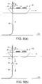
- Figure 9(a) shows a pipelaying vessel 80 advancing along a pipeline path during pipelaying.
- the vessel 80 is laying a pipeline in deep water using the J-lay method, taking pipe joints 82 from the deck, welding them successively to a pipeline end in a J-lay tower 84 and launching the resulting pipe string 86 downwardly into the sea.
- the pipe string 86 hangs as a catenary between the vessel 80 and the seabed 88.
- FIG 9(b) an abandonment procedure is underway.
- a PLET 90 has been attached to the pipeline end and is suspended by a sling 92 made up of sling sections 28, taken successively from storage on the deck of the vessel 80 and attached to each other end-to-end in the J-lay tower 84 before launching.
- the PLET 90 is attached to the sling 92 by a shackle 94 that may be attached to the bottom end of the sling 92 via a connector 70, 72 that is not shown in these figures but is as shown in Figures 7(a) or 7(b) .
- the vessel 80 continues to advance along the pipeline path as abandonment proceeds.
- Figure 9(c) shows the PLET 90 and pipeline end lowered to an intermediate depth at which a low-capacity winch 96 and wire 98 can take over abandonment duties.
- tension in the sling 92 and the pipe string 86 below has been being transferred from the tensioner of the J-lay tower 84 to the winch 96 on the vessel 80, which lowers the PLET 90 and pipeline end to the seabed 88.
- the vessel 80 continue to advance along the pipeline path as abandonment proceeds.
- Figure 9(d) shows the situation immediately after the PLET 90 and the pipeline end have been laid on the seabed.
- the vessel has stopped and has used an ROV (not shown) or other known technique to disengage the sling 92 from the PLET 90.
- the sling 92 is now being raised by the winch 96 and wire 98.
- the vessel 80 may then depart, to return when it is able to resume pipelaying.
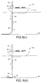
- FIG 10(a) the vessel 80 has returned and located the PLET 90, and a recovery procedure is underway.
- a sling 92 has been assembled from sling sections 28 in the J-lay tower 84 in the manner described above, lowered to the seabed 88 by the winch, and engaged to the PLET 90.
- the PLET 90 and pipeline end are being raised by the winch to an intermediate depth within the capacity of the winch 96 and its wire 98.
- the vessel 80 will move as necessary to prevent unnecessary stress on the pipe string 86 while it is being raised.
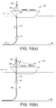
- the upper end of the sling 92 reaches the vessel 80 and the tension of the pipe string 86 is transferred from the winch 96 to the J-lay tower 84. This situation is shown in Figure 10(b) .
- the sling 92 then carries the increasing load as the PLET 90 and pipeline end near the surface.
- sling sections 28 are disengaged from the top of the sling 92 in the J-lay tower 84 and returned to storage on the deck of the vessel 80 as shown for re-use.
- FIG 10(c) shows the PLET 90 removed from the pipe string 86, which is now supported once more by the tensioner of the J-lay tower 84 ready for pipelaying to resume as shown in Figure 9(a) .
- a sling made up of the sling sections of the invention could be used to abandon and recover a pipeline all the way to and from the seabed.
- material selections and details such as port and filter arrangements may be varied without departing from the inventive concept.
Landscapes
- Engineering & Computer Science (AREA)
- General Engineering & Computer Science (AREA)
- Mechanical Engineering (AREA)
- Laying Of Electric Cables Or Lines Outside (AREA)
- Earth Drilling (AREA)
- Load-Engaging Elements For Cranes (AREA)
Description
- This invention relates to abandonment and recovery or 'A&R' procedures used in marine pipelaying, in which a floating vessel such as a barge is used to lay an offshore pipeline.
- The invention has particularly advantages when used with J-lay pipelaying equipment and it will be described in that context, but it is not necessarily limited to J-lay applications.
- The J-lay technique is suitable for pipelaying in deep water. It involves welding together successive pipe sections or 'joints' in an upright orientation in a J-lay tower on a pipelaying vessel. The resulting pipe string is launched downwardly into the water as it is formed. The pipe string adopts a single bend as it nears the seabed to lend a J-shape to the pipe string extending between the vessel and the seabed - hence 'J-lay'.
- J-lay is necessary in deep water because the pipe string with attached accessories extending from the pipelaying vessel to the seabed is extremely heavy, typically weighing hundreds of tonnes. To avoid buckling, the pipe string must bear that weight in tension, suspended from a holding device on the J-lay tower.
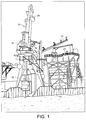
- An example of a J-lay pipelaying vessel is the Applicant's derrick lay barge Acergy Polaris. The operation of Acergy Polaris during pipelaying will now be outlined with reference to
Figures 1 and2 of the drawings. It should be noted that this example is given simply to put the invention into context and so does not limit the scope of the invention. In those drawings: - Figure 1
- is a side view of a J-Lay tower on a barge; and
- Figure 2
- is a perspective view of an erector arm loading a double joint into the tower of
Figure 1 . - Referring to
Figures 1 and2 , the J-lay tower 10 of thebarge 12 is supplied withdouble joints 14 of pipe made onshore, which are stored horizontally on thedeck 16. As required, thedouble joints 14 are lifted successively in horizontal orientation from thedeck 16 to atower entry level 18 using apipe elevator system 20 best shown inFigure 2 . Here, adouble joint 14 is loaded into apivoting erector arm 22, which upends thedouble joint 14 into an upright orientation and passes it over to a tower handling system comprising atensioner 24. Thedouble joint 14 is then lowered and aligned with the pipeline end held in a support bushing at a work station 26 on thetower 10. - The
double joint 14 is welded to the pipeline end at the work station 26 before the load of the pipe string is transferred from the support bushing to thetensioner 24 near the top of the J-lay tower 10. The completed pipe string is then lowered down to the support bushing for the addition of the nextdouble joint 14. Thetensioner 24 and the support bushing alternate to grip the pipeline end, interacting in a so-called 'hand-overhand' manner. - 'Abandonment and recovery' refers to the procedures of laying down and retrieving a pipeline end from the seabed. Those procedures are necessary during normal pipelaying start-up and termination. They are also necessary whenever pipelaying must be interrupted and resumed. For example, the pipelaying vessel may suffer a critical breakdown. More commonly, pipelaying is interrupted due to deteriorating weather conditions, which may stress the pipeline and reduce its fatigue life as the pipelaying vessel rolls and pitches in a rough sea or if it has difficulty remaining in position due to winds and currents. In such cases, the pipelaying vessel may need to abandon the pipeline end and leave the work area. When the problem that caused abandonment has passed, the vessel will return later to recover the pipeline end and resume pipelaying.
- Abandonment involves attaching a cap to the pipeline end, typically a pipeline end terminal or 'PLET'. A shackle is attached to a hook on the PLET to secure a wire running through a winch on the pipelaying vessel, and tension is transferred from the tensioner of the J-lay tower to the winch. The winch then lowers the PLET into the sea until the pipeline and PLET rest on the seabed. The wire is then detached from the hook of the PLET, for example using a remote-controlled linkage or an ROV, and is retracted by the vessel for storage.
- A recovery buoy is attached to the PLET during abandonment, enabling the PLET and the pipeline end to be located and retrieved during a subsequent recovery procedure. In essence, the recovery procedure is the reverse of abandonment as the wire is reattached to the PLET, typically using an ROV, and the PLET with the attached pipeline end is winched back up to the pipelaying vessel for pipelaying to resume.
- It may be possible in some situations for the pipelaying vessel to remain on station above the abandoned pipeline, for example while riding out a period of bad weather. In that case, the wire may be kept attached to the PLET resting on the seabed until the bad weather has passed. This eases the recovery procedure considerably.
- Traction (capstan) winches are generally used in A&R procedures to handle the high top tensions characteristic of deep-water pipelaying. Such winches require a continuous length of wire, generally of steel. That wire must be of large diameter - typically 70 mm to 120 mm - to support the great weight of the pipe string that extends above the seabed as the pipeline end nears the surface. Obviously, the wire must also be very long: generally several thousand metres long. Consequently, the wire itself may weigh in excess of 300 tonnes, and it takes up a great deal of space on the vessel when not in use. It also requires a large, powerful and hence expensive winch.
- Until recently, it was not possible to manufacture continuous lengths of wire of the necessary diameter. Indeed, A&R wires remain a high-cost item. They are also susceptible to damage, particularly in the corrosive marine environment, and so have a limited life. If damaged, the whole wire may have to be down-rated or rejected; this makes it advisable for the pipelaying vessel to carry a spare wire but this, of course, doubles the problems of high cost and storage space.
- Multiple winch and wire systems have been proposed in an effort to mitigate the problems of using A&R wires. An example is disclosed in
US Patent No. 7,507,755 , assigned to Subsea 7 Ltd. This recognises that A&R operations do not always take place at extremes of depth and that those operations can be handled more conveniently, where possible, with a smaller-capacity wire and winch than with a larger-capacity wire and winch. Consequently, pipelaying vessels are often equipped with both larger-capacity and smaller-capacity wires and winches. - These differently-rated wires and winches may be used together or successively. For example, when abandoning a pipeline, the larger-capacity wire and winch may be used to lower the pipeline end to an intermediate depth at which the top tension reduces to an extent that the load can be transferred to the smaller-capacity wire and winch. The higher-capacity wire can then be disconnected from the pipeline end and retracted to the pipelaying vessel. The smaller-capacity wire and winch then takes over to lower the pipeline end the rest of the way to the seabed. This means that a shorter length of larger-diameter wire is required on the drum of the higher-capacity winch, reducing space requirements and potentially also cost. However each wire remains vulnerable to damage and if spares are kept on board for both wires, the pipelaying vessel must accommodate four wires and not just two. This consumes space and reduces any cost advantage.
- It has been proposed to use complete single lengths of synthetic rope with traction winches for A&R purposes but that is not yet a proven technology. It is also noted that any damage to any part of a continuous rope may lead to the entire rope being down-rated or rejected, like a wire.
-
US 2003/0099A15 A1 WO 2005/005874 A1 discloses a method of abandoning a pipeline during subsea pipelaying using a plurality of sling sections. - It is against this background that the present invention has been devised. In one sense, the invention resides in a sling section cooperable with like sling sections to form a sling for use in abandonment or recovery of a pipeline, the sling section being elongate to define opposed ends, and comprising: a first end-piece at one end of the sling section; and a second end-piece at the opposite end of the sling section. The sling section further comprises: complementary connector formations associated with each respective end-piece, each connector formation being cooperable, in use when forming a sling, with a complementary connector formation of a neighbouring like sling section in the sling; a tensile load-bearing sling element extending between the end-pieces; and a sleeve around the sling element.
- For use in the context of a J-lay operation, the sling section is capable of being handled by pipe-joint handling apparatus associated with a J-lay tower. To this end, the sleeve is more resistant to bending than the sling element, and is preferably torsionally stiffer than the sling element.
- Advantageously, the sleeve suitably extends between, and is supported by, the end-pieces. Preferably, the sleeve is movable longitudinally with respect to at least one of the end-pieces to accommodate extension or contraction of the sling element in use.
- In the embodiments to be described, the sleeve is spaced from the sling element. In that case, the sling section preferably comprises a port for admitting water to the space between the sleeve and the sling element when the sling section is submerged in use.
- The sling element suitably extends along a central longitudinal axis of the sling section, and is preferably coaxial with the sleeve in cross-section.
- The sling element preferably terminates in anchor parts at each end, the anchor parts being cooperable with the end-pieces. The anchor parts may be flexibly attached to the end-pieces, for example by being pivotably attached to the end-pieces.
- To avoid twisting of the sling element in use, it is preferred that the end pieces engage with the sleeve to resist relative angular movement between the end pieces and the sleeve around the central longitudinal axis of the sling section.
- The inventive concept encompasses a sling comprising a plurality of sling sections in accordance with the invention.
- The sling sections of the invention enable, and the inventive concept embraces, methods of abandoning and recovering a pipeline during subsea pipelaying.
- One such method is a method of abandoning a pipeline during subsea pipelaying, according to the subject matter of claim 15.
- Preferably, the sling sections are releasably engaged to the upper end of the sling in a J-lay tower that launches the sling into the sea. Another such method is a method of recovering a pipeline during subsea pipelaying, according to the subject matter of claim 17. Preferably, the sling sections are disengaged from an upper end of the sling in a J-lay tower that lifts the sling from the sea.
- Thus, preferred embodiments of the invention employ sections of substantially non-metallic sling elements encased in a buoyant or near-buoyant non-metallic sleeve fitted with a means of quick connection on each end. The assembly is handled much as a conventional pipe would be in a J-lay system, and as a result handling time is minimised.
- The sling element and the sleeve are preferably of synthetic polymers designed to be as near neutrally buoyant as possible in water: this means that the top tension will reduce with each section launched. The outcome of this is that the sling of the invention need not be deployed all the way to the seabed: deployment may be limited to the depth that more conventional (and faster) wire A&R systems can take over. As top tension will have reduced substantially by that stage, a relatively low-capacity winch and wire can be used that is more compact, less expensive and more convenient than the higher-capacity winch and wire that would otherwise be necessary to handle A&R duties.
- Light weight is beneficial for the sling sections of the present invention as this reduces top tension as the sling is progressively abandoned and the pipeline end is lowered. However, neutral buoyancy or slightly negative buoyancy is preferred to positive buoyancy for the sling sections. Whilst positive buoyancy would be good for reducing top tension, it may present challenges in controlling the sling once a load has been released from it.
- Another advantage of the invention is that if a section of sling is damaged, only that one section need be rejected and replaced with another section at reduced cost. The cost of emergency spares carried on board the pipelaying vessel is also reduced.
- Reference has already been made to
Figures 1 and2 of the accompanying drawings to put the invention into context. In order that the invention may be more readily understood, reference will now be made, by way of example, to the remaining drawings in which: -
Figure 3 is a sectional side view of a sling section in accordance with the present invention; -
Figure 4 is a perspective view of a male connector at one end of the sling section shown inFigure 3 ; -
Figures 5(a) and 5(b) are side sectional views of end pieces having, respectively, male and female connectors showing additional details including flooding, filtering and sealing arrangements; -
Figure 6 is a sectional perspective view showing how the male connector shown inFigures 3 ,4 and5(a) is received within and secured to a complementary female connector shown inFigure 5(b) at the adjoining opposite end of an identical neighbouring sling section; -
Figures 7(a) and 7(b) are side sectional views of, respectively, variants of the male and female connectors shown inFigures 5(a) and 5(b) , those variants being for use connecting an end of the sling to other objects such as a wire that suspends the sling or to a load such as a PLET suspended by the sling; -
Figure 8 is a sectional side view corresponding toFigure 3 , in which there are modifications to the end pieces and the sleeve shown in that Figure; -
Figures 9(a) to 9(d) are schematic views showing some steps involved in an abandonment procedure employing the sling sections of the invention; and -
Figures 10(a) to 10(c) are schematic views showing some steps involved in a recovery procedure employing the sling sections of the invention. - Referring specifically now to
Figure 3 , asling section 28 in accordance with the invention comprises four main components, namely: - a
sling element 30, being a tensile member extending along the central longitudinal axis of thesling section 28; - a circular-
section tubular sleeve 32 surrounding thesling element 30 and extending along its length, being concentric with and spaced from thesling element 30; and - two opposed end-
pieces sleeve 32 and that anchor the respective opposed ends of thesling element 30. - One end-piece of the
sling section 28 comprises amale connector 38, shown externally inFigure 4 and in cross-sectional detail inFigure 5(a) , and the other end-piece comprises a complementaryfemale connector 40, shown in cross-sectional detail inFigure 5(b) , for receiving themale connector 38 of an identicalneighbouring sling section 28. Theconnectors Figure 6 . - The
sling section 28 emulates the length, diameter and circular cross-section of a conventional pipe joint used in a J-lay system. For the purposes of this specification, 'pipe joint' may be taken to include longer pipe sections such as double joints and quad joints. - Thus being, in effect, a pipe joint analogue, the
sling section 28 can be handled on a pipelaying vessel in much the same way as a pipe joint would be. Thesling section 28 can therefore be lifted from storage on the deck of the vessel into the J-lay tower, and from there it can be engaged to a precedingsling section 28 by means of the quick-action connectors - Similarly, recovery involves the reverse operation of disengaging and separating each
sling section 28 from thesling section 28 below as the sling is raised from the water via the J-lay tower. Again, saving time is important during recovery as it allows the vessel to resume pipelaying as quickly as possible. - The
sleeve 32 is an extruded polymer pipe, for example of high-density polyethylene with a typical wall thickness of 60mm. Thesleeve 32 does not merely emulate a pipe joint: it also helps to protect thesling element 30 from abrasion and other mechanical damage and also from UV degradation during use, especially during handling and when lying on the deck of the pipelaying vessel awaiting use. Thesleeve 32 also creates a protective barrier around thesling element 30 when underwater. - The
sling section 28 will typically be rated for a top tension of 750 tons with a safety factor of three. - The
sling element 30 forming the load-bearing core of thesling section 28 is of a lightweight, high-strength synthetic material such as aramid- or carbon-fibre composites, or ultra-high molecular weight polyethylene (UHMWPE) sold, for example, under the trade mark Dyneema. Aramid composites, sold for example under the trade mark Kevlar, are currently preferred for their low creep characteristics and slightly negative buoyancy. - Each end of the
sling element 30 is attached to a respectiveenlarged anchor part 42 that cooperates with a respective one of the end-pieces. Theanchor parts 42 and the end-pieces - Referring now also to
Figures 5(a) and 5(b) , each end-piece sling section 28 has ahollow plug part 44 of skirt-like circular-section that fits closely within a respective end of thesleeve 32. Theplug part 44 of each end-piece cup 46 that receives a respective one of theanchor parts 42 of thesling element 30, as shown inFigure 3 . - A transverse bore transects each end-piece in alignment with a bore extending through the
anchor part 42 received in thecup 46, such that apin 48 extending through the aligned bores fixes theanchor part 42 in thecup 46. The pin attachment lends a degree of flexibility to the connection between theanchor part 42 and the associated end-piece such sections 28. - The space between the
sling element 30 and thesleeve 32 must be allowed to flood to equalise pressure as the sling submerges. Water must therefore be free to enter and air must be free to escape from that space. For this purpose, each end-piece port 50 that communicates between the space and the exterior of thesling section 28. Thatport 50 extends from thecup 46 outwardly through the remainder of the end-piece sling section 28. - A
filter 52 extends across eachport 50 at the base of thecup 46. The purpose of thefilter 52 is to keep sand and other debris out of the space between thesling element 30 and thesleeve 32. Otherwise, abrasives such as sand could enter the matrix of thesling element 30 and hence damage and degrade thesling element 30 over time. For the same reason, adirt seal 54 extends circumferentially around theplug part 44 of each end-piece sleeve 32. - The end-
piece 34 with themale connector 38 has ashoulder 56 that bears against its end of thesleeve 32 when theplug part 44 of that end-piece 34 is fully inserted into thesleeve 32. Conversely, the inner part of the end-piece 36 with thefemale connector 40 has no corresponding shoulder and is a sliding fit within its end of thesleeve 32. In this way, thefemale connector 40 can move in or out with respect to thesleeve 32 as the length of thesling element 30 varies slightly with creep or elastic deformation under varying loads in use. - The male and
female connectors - As
Figures 3 ,4 and5(a) show, themale connector 38 comprises astud 58 of circular cross section extending along the central longitudinal axis of thesling section 28. Thatstud 58 is encircled by spacedcircumferential ridges 60 lying in planes perpendicular to the central longitudinal axis. -
Figures 3 and5(b) show that thefemale connector 40 has a recess that lies on the central longitudinal axis of thesling section 28 and is complementary to thestud 58 of themale connector 38. Lockingdogs 62 with ridged formations complementary to the ridges of thestud 58 are spaced equi-angularly around the recess. The lockingdogs 62 are movable radially in response to axial movement of alocking collar 64. The lockingcollar 64 is turned around anexternal thread 66 on thefemale connector 40 to interact in cam-like manner with the lockingdogs 62 to lock and release the coupling as required. -
Figure 6 shows that when fully inserted into the corresponding recess of thefemale connector 40 of a neighbouringsling section 28, thestud 58 is engaged by the lockingdogs 62 that move radially inwardly as the lockingcollar 64 is advanced along itsthread 66, to lock thestud 58 against axial movement. - The circular cross-sections of the
stud 58 and the corresponding recess allow for relative pivotal movement of neighbouringsling sections 28 around their common central longitudinal axis. The resulting ability for the sling, as a whole, to twist enhances the flexibility of a sling made up of manysuch sling sections 38. - Further circumferential ridges encircle 68 the end-piece with the
male connector 38, those ridges serving as upper and lower collar supports. Theridges 68 are accessible to a tensioner of a J-lay tower when the sling is assembled, to enable tension to be applied to the sling section 28 - and hence to a sling made up of such sections - without damaging thesleeve 32. - In summary:
- the
sling element 30 is the load-bearing part of thesling section 28; - the
sleeve 32 allows efficient handling of thesling section 28 and helps to protect thesling element 30; and - the end-
pieces connectors sling section 28 allow fast interconnection to neighbouringsling sections 28 and the application of tension to a sling made up of several such sections. -
Figures 7(a) and 7(b) show connectors 70, 72 to be used for connecting other objects to theterminal sling sections 28 of the sling. Examples of such objects are a wire that suspends the sling or a shackle for attachment to a load such as a PLET suspended by the sling. - The
connectors 70, 72 shown inFigures 7(a) and 7(b) have, respectively, male andfemale connector formations female connectors pieces padeye formation 74 replaces theplug parts 44 of those end-pieces padeye formation 74 enables attachment of theconnectors 70 to such other objects as may be necessary. Theconnector 70, 72 can then be attached quickly and easily to a male orfemale connector -
Figure 8 shows a variant of thesling section 28 ofFigure 3 , in which the end-pieces sleeve 32 are modified. The modification engages the end-pieces sleeve 32 to resist relative angular movement around the central longitudinal axis of thesling section 28. Such movement could otherwise occur due to torsional stresses that may arise in the sling in use; if that happens, thesling elements 30 of thesling sections 28 could twist undesirably. - In the variant shown in
Figure 8 , the end-pieces sleeve 32 because thepins 48 that secure theanchor parts 42 of thesling element 30 in thecups 46 extend beyond the diameter of therespective plug parts 44. The protruding ends of thepins 48 engage inopposed holes 76 orslots 78 extending through the wall of thesleeve 32.Holes 76 extend through the wall of thesleeve 32 near its end having themale connector 38 whereas longitudinally-extendingslots 78 extend through the wall of thesleeve 32 near its end having thefemale connector 40. Theseslots 78 allow the end-piece 36 with thefemale connector 40 to move longitudinally with respect to thesleeve 32 for the reasons explained previously, while preventing angular movement around the central longitudinal axis of thesling section 28. The end-piece 34 with themale connector 38 has no provision to move in the same manner, hence the use ofholes 76 instead ofslots 78 at that end of thesleeve 32. - Moving on finally now to
Figures 9(a) to 10(c) , these schematic drawings show how thesling sections 28 of the invention can be used in abandonment and recovery procedures. Details such as the use of a recovery buoy have been omitted for clarity. -
Figure 9(a) shows apipelaying vessel 80 advancing along a pipeline path during pipelaying. Thevessel 80 is laying a pipeline in deep water using the J-lay method, takingpipe joints 82 from the deck, welding them successively to a pipeline end in a J-lay tower 84 and launching the resultingpipe string 86 downwardly into the sea. Thepipe string 86 hangs as a catenary between thevessel 80 and theseabed 88. - In
Figure 9(b) , an abandonment procedure is underway. APLET 90 has been attached to the pipeline end and is suspended by asling 92 made up ofsling sections 28, taken successively from storage on the deck of thevessel 80 and attached to each other end-to-end in the J-lay tower 84 before launching. ThePLET 90 is attached to thesling 92 by ashackle 94 that may be attached to the bottom end of thesling 92 via aconnector 70, 72 that is not shown in these figures but is as shown inFigures 7(a) or 7(b) . Thevessel 80 continues to advance along the pipeline path as abandonment proceeds. -
Figure 9(c) shows thePLET 90 and pipeline end lowered to an intermediate depth at which a low-capacity winch 96 andwire 98 can take over abandonment duties. Hence, tension in thesling 92 and thepipe string 86 below has been being transferred from the tensioner of the J-lay tower 84 to thewinch 96 on thevessel 80, which lowers thePLET 90 and pipeline end to theseabed 88. Thevessel 80 continue to advance along the pipeline path as abandonment proceeds. -
Figure 9(d) shows the situation immediately after thePLET 90 and the pipeline end have been laid on the seabed. The vessel has stopped and has used an ROV (not shown) or other known technique to disengage thesling 92 from thePLET 90. Thesling 92 is now being raised by thewinch 96 andwire 98. Thevessel 80 may then depart, to return when it is able to resume pipelaying. - In
Figure 10(a) , thevessel 80 has returned and located thePLET 90, and a recovery procedure is underway. Here, asling 92 has been assembled fromsling sections 28 in the J-lay tower 84 in the manner described above, lowered to theseabed 88 by the winch, and engaged to thePLET 90. ThePLET 90 and pipeline end are being raised by the winch to an intermediate depth within the capacity of thewinch 96 and itswire 98. Thevessel 80 will move as necessary to prevent unnecessary stress on thepipe string 86 while it is being raised. - Before the
winch 96 andwire 98 reach their safe limit, the upper end of thesling 92 reaches thevessel 80 and the tension of thepipe string 86 is transferred from thewinch 96 to the J-lay tower 84. This situation is shown inFigure 10(b) . Thesling 92 then carries the increasing load as thePLET 90 and pipeline end near the surface. As thesling 92 is progressively recovered from the water,sling sections 28 are disengaged from the top of thesling 92 in the J-lay tower 84 and returned to storage on the deck of thevessel 80 as shown for re-use. - Finally
Figure 10(c) shows thePLET 90 removed from thepipe string 86, which is now supported once more by the tensioner of the J-lay tower 84 ready for pipelaying to resume as shown inFigure 9(a) . - Many variations are possible within the inventive concept as disclosed in the appended claims. For example, a sling made up of the sling sections of the invention could be used to abandon and recover a pipeline all the way to and from the seabed. Also, material selections and details such as port and filter arrangements may be varied without departing from the inventive concept.
Claims (18)
- A sling section (28) cooperable with like sling sections (28) to form a sling for use in abandonment or recovery of a pipeline, the sling section (28) being elongate to define opposed ends, and comprising:a first end-piece (34) at one end of the sling section (28); and a second end-piece (36) at the opposite end of the sling r section (28);wherein the sling section (28) further comprises:complementary connector formations (38, 40) associated with each respective end-piece (34, 36), each connector formation (38, 40) being cooperable, in use when forming a sling, with a complementary connector formation (38, 40) of a neighbouring like sling section (28) in the sling;a tensile load-bearing sling element (30) extending between the end-pieces (34, 36); anda sleeve (32) around the sling element (30).
- The sling section of Claim 1, wherein the sleeve (32) extends between, and is supported by, the end-pieces (34, 36).
- The sling section of Claim 2, wherein the sleeve (32) is movable longitudinally with respect to at least one of the end-pieces (34, 36).
- The sling section of any preceding claim, wherein the sleeve (32) is spaced from the sling element (30).
- The sling section of any preceding claim, wherein the sleeve (32) is more resistant to bending than the sling element (30).
- The sling section of any preceding claim, wherein the sleeve (32) is torsionally stiffer than the sling element (30).
- The sling section of any preceding claim, further comprising a port (50) for admitting water to the space between the sleeve (32) and the sling element (30) when the sling section (28) is submerged in use.
- The sling section of any preceding claim, wherein the sling element (30) extends along a central longitudinal axis of the sling section (28).
- The sling section of Claim 8, wherein the sling element (30) is coaxial with the sleeve (32) in cross-section.
- The sling section of any preceding claim, wherein the sling element (30) terminates in anchor parts (42) at each end, the anchor parts (42) being cooperable with the end-pieces (34, 36).
- The sling section of Claim 10, wherein the anchor parts (42) are flexibly attached to the end-pieces (34, 36).
- The sling section of Claim 11. wherein the anchor parts (42) are pivotably attached to the end-pieces (34, 36).
- The sling section of any preceding claim, wherein at least one end piece (34, 36) engages with the sleeve (32) to resist relative angular movement between the end piece (34, 36) and the sleeve (32) around the central longitudinal axis of the sling section (28).
- A sling comprising a plurality of sling sections (28) as defined in any preceding claim.
- A method of abandoning a pipeline during subsea pipelaying, the method comprising:attaching a connector (38, 40) to a pipeline end;releasably engaging a sling section (28) to the connector (38, 40) to start creating a sling,wherein the sling section (28) is elongate to define opposed ends and comprises:a first end-piece (34) at one end of the sling r section (28);a second end-piece (36) at the opposite end of the sling section (28);a tensile load-bearing sling element (30) extending between the end-pieces (34, 36); anda sleeve (32) around the sling element (30);and, in succession, releasably engaging a plurality of like sling sections (28) to an upper end of the sling while lowering the pipeline end into the sea.
- The method of Claim 15, wherein the sling sections (28) are releasably engaged to the upper end of the sling in a J-lay tower (84) that launches the sling into the sea.
- A method of recovering a pipeline during subsea pipelaying, the method comprising raising the pipeline end using a sling made up of successive sling sections (28) releasably engaged to each other in end-to-end relation, while successively disengaging sling sections (28) from an upper end of the sling, wherein each sling section (28) is elongate to define opposed ends and comprises:a first end-piece (34) at one end of the sling section (28);a second end-piece (36) at the opposite end of the sling section (28);a tensile load-bearing sling element (30) extending between the end-pieces (34, 36); anda sleeve (32) around the sling element (30).
- The method of Claim 17, wherein the sling sections (28) are disengaged from an upper end of the sling in a J-lay tower (84) that lifts the sling from the sea.
Applications Claiming Priority (2)
| Application Number | Priority Date | Filing Date | Title |
|---|---|---|---|
| GB1000357.2A GB2476823B (en) | 2010-01-11 | 2010-01-11 | Improvements relating to abandonment and recovery of pipelines |
| PCT/GB2011/050028 WO2011083340A1 (en) | 2010-01-11 | 2011-01-10 | Improvements relating to abandonment and recovery of pipelines |
Publications (2)
| Publication Number | Publication Date |
|---|---|
| EP2524162A1 EP2524162A1 (en) | 2012-11-21 |
| EP2524162B1 true EP2524162B1 (en) | 2016-08-10 |
Family
ID=41819152
Family Applications (1)
| Application Number | Title | Priority Date | Filing Date |
|---|---|---|---|
| EP11701545.3A Active EP2524162B1 (en) | 2010-01-11 | 2011-01-10 | Improvements relating to abandonment and recovery of pipelines |
Country Status (6)
| Country | Link |
|---|---|
| US (1) | US8950977B2 (en) |
| EP (1) | EP2524162B1 (en) |
| AU (1) | AU2011204506B2 (en) |
| BR (1) | BR112012017008B1 (en) |
| GB (1) | GB2476823B (en) |
| WO (1) | WO2011083340A1 (en) |
Families Citing this family (11)
| Publication number | Priority date | Publication date | Assignee | Title |
|---|---|---|---|---|
| EP2667071B1 (en) | 2012-05-24 | 2016-01-06 | Technip France | Method of laying a pipeline |
| KR101444378B1 (en) | 2013-01-30 | 2014-09-26 | 삼성중공업 주식회사 | End head device for pipeline and installation method of pipeline with pipeline end terminations using the same |
| GB2510569B (en) * | 2013-02-06 | 2015-12-02 | Subsea 7 Ltd | Improvements relating to abandonment and recovery of pipelines |
| NL2010375C2 (en) | 2013-02-28 | 2014-09-01 | Ihc Sea Steel Ltd | Pile driving guide. |
| KR101652353B1 (en) | 2014-08-29 | 2016-09-01 | 삼성중공업 주식회사 | Pipeline laying vessel applied Abandonment and recovery method using reel |
| NL2017560B1 (en) | 2016-09-30 | 2018-04-10 | Ihc Iqip Uk Ltd | Pile guide comprising a base frame and a guide member |
| NL2018569B1 (en) * | 2017-03-23 | 2018-10-03 | Bluemarine Offshore Yard Service Bv | Abandonment and recovery system for a subsea pipeline |
| CN106969200B (en) * | 2017-04-24 | 2018-11-27 | 中国海洋石油集团有限公司 | The recyclable device of deep-water subsea pipeline |
| GB2576333C (en) * | 2018-08-14 | 2024-05-08 | Subsea 7 Do Brasil Servicos Ltda | Handling loads in subsea operations |
| GB2576767B (en) | 2018-08-31 | 2020-09-16 | Acergy France SAS | Abandonment and recovery of pipelines |
| AU2020366323B2 (en) * | 2019-10-18 | 2024-05-30 | J. Ray Mcdermott, S.A. | A stinger for a pipe laying operation |
Family Cites Families (9)
| Publication number | Priority date | Publication date | Assignee | Title |
|---|---|---|---|---|
| US4093292A (en) * | 1974-04-01 | 1978-06-06 | Jose Maria Maso Marcet | Sling and its method of manufacture |
| FR2479943B1 (en) | 1980-04-04 | 1985-07-05 | Petroles Cie Francaise | PROCESS AND LINE FOR DEPOSITING A PIPELINE AT SEA |
| US5984012A (en) * | 1998-03-16 | 1999-11-16 | Cooper Cameron Corporation | Emergency recovery system for use in a subsea environment |
| GB9930492D0 (en) * | 1999-12-23 | 2000-02-16 | Saipem Spa | Improvements in and relating to laying of pipeline |
| GB0316375D0 (en) * | 2003-07-12 | 2003-08-13 | Stolt Offshore Sa | Method and associated apparatus for abandonment and recovery at sea |
| US7256207B2 (en) | 2003-08-20 | 2007-08-14 | Irm Llc | Inhibitors of cathepsin S |
| GB2434627B (en) * | 2006-01-31 | 2010-10-20 | Subsea 7 Ltd | Apparatus and method for laying down, abandoning and recovering a pipe on the sea floor |
| US7621697B2 (en) * | 2006-04-19 | 2009-11-24 | Allseas Group S.A. | Abandonment and recovery system and method, and cable connector |
| US8469633B2 (en) | 2008-05-28 | 2013-06-25 | Heerema Marine Contractors Nederland B.V. | Vessel with abandoning and recovering system for pipelines, method, and use of said vessel and system |
-
2010
- 2010-01-11 GB GB1000357.2A patent/GB2476823B/en active Active
-
2011
- 2011-01-10 EP EP11701545.3A patent/EP2524162B1/en active Active
- 2011-01-10 AU AU2011204506A patent/AU2011204506B2/en active Active
- 2011-01-10 WO PCT/GB2011/050028 patent/WO2011083340A1/en active Application Filing
- 2011-01-10 US US13/521,735 patent/US8950977B2/en active Active
- 2011-01-10 BR BR112012017008A patent/BR112012017008B1/en active IP Right Grant
Also Published As
| Publication number | Publication date |
|---|---|
| US8950977B2 (en) | 2015-02-10 |
| US20130115007A1 (en) | 2013-05-09 |
| AU2011204506A1 (en) | 2012-08-30 |
| GB2476823B (en) | 2012-05-02 |
| GB2476823A (en) | 2011-07-13 |
| EP2524162A1 (en) | 2012-11-21 |
| AU2011204506B2 (en) | 2015-12-10 |
| BR112012017008B1 (en) | 2020-04-28 |
| GB201000357D0 (en) | 2010-02-24 |
| BR112012017008A2 (en) | 2016-04-05 |
| WO2011083340A1 (en) | 2011-07-14 |
Similar Documents
| Publication | Publication Date | Title |
|---|---|---|
| EP2524162B1 (en) | Improvements relating to abandonment and recovery of pipelines | |
| US8262319B2 (en) | Freestanding hybrid riser system and method of installation | |
| US10597952B2 (en) | Steel catenary riser top interface | |
| US11846144B2 (en) | Handling loads in subsea operations | |
| EP3534049B1 (en) | Tendon element for abandonment and recovery of pipelines | |
| EP3844428B1 (en) | Abandonment and recovery of pipelines | |
| CN113212656B (en) | Pipe cable lifting method for single-point cabin | |
| US11236550B2 (en) | Fabrication of pipe bundles offshore | |
| EP4386243A1 (en) | Submarine reel drive system and method for reeling in and launching flexible pipes and umbilicals | |
| NL2006810C2 (en) | Recovery device for recovering a pipeline after the abandonment thereof on the seabed on an s-lay vessel. | |
| CN118119549A (en) | Disconnectable yoke mooring system and method of use thereof |
Legal Events
| Date | Code | Title | Description |
|---|---|---|---|
| PUAI | Public reference made under article 153(3) epc to a published international application that has entered the european phase |
Free format text: ORIGINAL CODE: 0009012 |
|
| 17P | Request for examination filed |
Effective date: 20120810 |
|
| AK | Designated contracting states |
Kind code of ref document: A1 Designated state(s): AL AT BE BG CH CY CZ DE DK EE ES FI FR GB GR HR HU IE IS IT LI LT LU LV MC MK MT NL NO PL PT RO RS SE SI SK SM TR |
|
| DAX | Request for extension of the european patent (deleted) | ||
| RAP1 | Party data changed (applicant data changed or rights of an application transferred) |
Owner name: SUBSEA 7 LIMITED |
|
| RIC1 | Information provided on ipc code assigned before grant |
Ipc: F16L 1/16 20060101AFI20160121BHEP Ipc: F16L 1/235 20060101ALI20160121BHEP Ipc: F16L 1/19 20060101ALI20160121BHEP Ipc: F16L 1/20 20060101ALI20160121BHEP Ipc: F16L 1/26 20060101ALI20160121BHEP |
|
| GRAP | Despatch of communication of intention to grant a patent |
Free format text: ORIGINAL CODE: EPIDOSNIGR1 |
|
| INTG | Intention to grant announced |
Effective date: 20160229 |
|
| GRAS | Grant fee paid |
Free format text: ORIGINAL CODE: EPIDOSNIGR3 |
|
| GRAA | (expected) grant |
Free format text: ORIGINAL CODE: 0009210 |
|
| AK | Designated contracting states |
Kind code of ref document: B1 Designated state(s): AL AT BE BG CH CY CZ DE DK EE ES FI FR GB GR HR HU IE IS IT LI LT LU LV MC MK MT NL NO PL PT RO RS SE SI SK SM TR |
|
| REG | Reference to a national code |
Ref country code: GB Ref legal event code: FG4D |
|
| REG | Reference to a national code |
Ref country code: CH Ref legal event code: EP Ref country code: AT Ref legal event code: REF Ref document number: 819366 Country of ref document: AT Kind code of ref document: T Effective date: 20160815 |
|
| REG | Reference to a national code |
Ref country code: IE Ref legal event code: FG4D |
|
| REG | Reference to a national code |
Ref country code: DE Ref legal event code: R096 Ref document number: 602011028971 Country of ref document: DE |
|
| REG | Reference to a national code |
Ref country code: NL Ref legal event code: FP |
|
| REG | Reference to a national code |
Ref country code: NO Ref legal event code: T2 Effective date: 20160810 |
|
| REG | Reference to a national code |
Ref country code: LT Ref legal event code: MG4D |
|
| REG | Reference to a national code |
Ref country code: FR Ref legal event code: PLFP Year of fee payment: 7 |
|
| REG | Reference to a national code |
Ref country code: AT Ref legal event code: MK05 Ref document number: 819366 Country of ref document: AT Kind code of ref document: T Effective date: 20160810 |
|
| PG25 | Lapsed in a contracting state [announced via postgrant information from national office to epo] |
Ref country code: FI Free format text: LAPSE BECAUSE OF FAILURE TO SUBMIT A TRANSLATION OF THE DESCRIPTION OR TO PAY THE FEE WITHIN THE PRESCRIBED TIME-LIMIT Effective date: 20160810 Ref country code: RS Free format text: LAPSE BECAUSE OF FAILURE TO SUBMIT A TRANSLATION OF THE DESCRIPTION OR TO PAY THE FEE WITHIN THE PRESCRIBED TIME-LIMIT Effective date: 20160810 Ref country code: IS Free format text: LAPSE BECAUSE OF FAILURE TO SUBMIT A TRANSLATION OF THE DESCRIPTION OR TO PAY THE FEE WITHIN THE PRESCRIBED TIME-LIMIT Effective date: 20161210 Ref country code: HR Free format text: LAPSE BECAUSE OF FAILURE TO SUBMIT A TRANSLATION OF THE DESCRIPTION OR TO PAY THE FEE WITHIN THE PRESCRIBED TIME-LIMIT Effective date: 20160810 Ref country code: LT Free format text: LAPSE BECAUSE OF FAILURE TO SUBMIT A TRANSLATION OF THE DESCRIPTION OR TO PAY THE FEE WITHIN THE PRESCRIBED TIME-LIMIT Effective date: 20160810 |
|
| PG25 | Lapsed in a contracting state [announced via postgrant information from national office to epo] |
Ref country code: AT Free format text: LAPSE BECAUSE OF FAILURE TO SUBMIT A TRANSLATION OF THE DESCRIPTION OR TO PAY THE FEE WITHIN THE PRESCRIBED TIME-LIMIT Effective date: 20160810 Ref country code: SE Free format text: LAPSE BECAUSE OF FAILURE TO SUBMIT A TRANSLATION OF THE DESCRIPTION OR TO PAY THE FEE WITHIN THE PRESCRIBED TIME-LIMIT Effective date: 20160810 Ref country code: PL Free format text: LAPSE BECAUSE OF FAILURE TO SUBMIT A TRANSLATION OF THE DESCRIPTION OR TO PAY THE FEE WITHIN THE PRESCRIBED TIME-LIMIT Effective date: 20160810 Ref country code: GR Free format text: LAPSE BECAUSE OF FAILURE TO SUBMIT A TRANSLATION OF THE DESCRIPTION OR TO PAY THE FEE WITHIN THE PRESCRIBED TIME-LIMIT Effective date: 20161111 Ref country code: LV Free format text: LAPSE BECAUSE OF FAILURE TO SUBMIT A TRANSLATION OF THE DESCRIPTION OR TO PAY THE FEE WITHIN THE PRESCRIBED TIME-LIMIT Effective date: 20160810 Ref country code: PT Free format text: LAPSE BECAUSE OF FAILURE TO SUBMIT A TRANSLATION OF THE DESCRIPTION OR TO PAY THE FEE WITHIN THE PRESCRIBED TIME-LIMIT Effective date: 20161212 Ref country code: ES Free format text: LAPSE BECAUSE OF FAILURE TO SUBMIT A TRANSLATION OF THE DESCRIPTION OR TO PAY THE FEE WITHIN THE PRESCRIBED TIME-LIMIT Effective date: 20160810 |
|
| PG25 | Lapsed in a contracting state [announced via postgrant information from national office to epo] |
Ref country code: EE Free format text: LAPSE BECAUSE OF FAILURE TO SUBMIT A TRANSLATION OF THE DESCRIPTION OR TO PAY THE FEE WITHIN THE PRESCRIBED TIME-LIMIT Effective date: 20160810 Ref country code: RO Free format text: LAPSE BECAUSE OF FAILURE TO SUBMIT A TRANSLATION OF THE DESCRIPTION OR TO PAY THE FEE WITHIN THE PRESCRIBED TIME-LIMIT Effective date: 20160810 |
|
| REG | Reference to a national code |
Ref country code: DE Ref legal event code: R097 Ref document number: 602011028971 Country of ref document: DE |
|
| REG | Reference to a national code |
Ref country code: NO Ref legal event code: CHAD Owner name: SUBSEA 7 LIMITED, GB |
|
| RAP2 | Party data changed (patent owner data changed or rights of a patent transferred) |
Owner name: SUBSEA 7 LIMITED |
|
| PG25 | Lapsed in a contracting state [announced via postgrant information from national office to epo] |
Ref country code: SM Free format text: LAPSE BECAUSE OF FAILURE TO SUBMIT A TRANSLATION OF THE DESCRIPTION OR TO PAY THE FEE WITHIN THE PRESCRIBED TIME-LIMIT Effective date: 20160810 Ref country code: SK Free format text: LAPSE BECAUSE OF FAILURE TO SUBMIT A TRANSLATION OF THE DESCRIPTION OR TO PAY THE FEE WITHIN THE PRESCRIBED TIME-LIMIT Effective date: 20160810 Ref country code: BG Free format text: LAPSE BECAUSE OF FAILURE TO SUBMIT A TRANSLATION OF THE DESCRIPTION OR TO PAY THE FEE WITHIN THE PRESCRIBED TIME-LIMIT Effective date: 20161110 Ref country code: CZ Free format text: LAPSE BECAUSE OF FAILURE TO SUBMIT A TRANSLATION OF THE DESCRIPTION OR TO PAY THE FEE WITHIN THE PRESCRIBED TIME-LIMIT Effective date: 20160810 Ref country code: DK Free format text: LAPSE BECAUSE OF FAILURE TO SUBMIT A TRANSLATION OF THE DESCRIPTION OR TO PAY THE FEE WITHIN THE PRESCRIBED TIME-LIMIT Effective date: 20160810 Ref country code: BE Free format text: LAPSE BECAUSE OF FAILURE TO SUBMIT A TRANSLATION OF THE DESCRIPTION OR TO PAY THE FEE WITHIN THE PRESCRIBED TIME-LIMIT Effective date: 20160810 |
|
| PLBE | No opposition filed within time limit |
Free format text: ORIGINAL CODE: 0009261 |
|
| STAA | Information on the status of an ep patent application or granted ep patent |
Free format text: STATUS: NO OPPOSITION FILED WITHIN TIME LIMIT |
|
| 26N | No opposition filed |
Effective date: 20170511 |
|
| REG | Reference to a national code |
Ref country code: DE Ref legal event code: R119 Ref document number: 602011028971 Country of ref document: DE |
|
| PG25 | Lapsed in a contracting state [announced via postgrant information from national office to epo] |
Ref country code: SI Free format text: LAPSE BECAUSE OF FAILURE TO SUBMIT A TRANSLATION OF THE DESCRIPTION OR TO PAY THE FEE WITHIN THE PRESCRIBED TIME-LIMIT Effective date: 20160810 |
|
| REG | Reference to a national code |
Ref country code: CH Ref legal event code: PL |
|
| PG25 | Lapsed in a contracting state [announced via postgrant information from national office to epo] |
Ref country code: MC Free format text: LAPSE BECAUSE OF FAILURE TO SUBMIT A TRANSLATION OF THE DESCRIPTION OR TO PAY THE FEE WITHIN THE PRESCRIBED TIME-LIMIT Effective date: 20160810 |
|
| PG25 | Lapsed in a contracting state [announced via postgrant information from national office to epo] |
Ref country code: CH Free format text: LAPSE BECAUSE OF NON-PAYMENT OF DUE FEES Effective date: 20170131 Ref country code: LI Free format text: LAPSE BECAUSE OF NON-PAYMENT OF DUE FEES Effective date: 20170131 |
|
| REG | Reference to a national code |
Ref country code: IE Ref legal event code: MM4A |
|
| PG25 | Lapsed in a contracting state [announced via postgrant information from national office to epo] |
Ref country code: DE Free format text: LAPSE BECAUSE OF NON-PAYMENT OF DUE FEES Effective date: 20170801 Ref country code: LU Free format text: LAPSE BECAUSE OF NON-PAYMENT OF DUE FEES Effective date: 20170110 |
|
| REG | Reference to a national code |
Ref country code: FR Ref legal event code: PLFP Year of fee payment: 8 |
|
| PG25 | Lapsed in a contracting state [announced via postgrant information from national office to epo] |
Ref country code: IE Free format text: LAPSE BECAUSE OF NON-PAYMENT OF DUE FEES Effective date: 20170110 |
|
| REG | Reference to a national code |
Ref country code: FR Ref legal event code: CA Effective date: 20180221 |
|
| PG25 | Lapsed in a contracting state [announced via postgrant information from national office to epo] |
Ref country code: MT Free format text: LAPSE BECAUSE OF NON-PAYMENT OF DUE FEES Effective date: 20170110 |
|
| PG25 | Lapsed in a contracting state [announced via postgrant information from national office to epo] |
Ref country code: AL Free format text: LAPSE BECAUSE OF FAILURE TO SUBMIT A TRANSLATION OF THE DESCRIPTION OR TO PAY THE FEE WITHIN THE PRESCRIBED TIME-LIMIT Effective date: 20160810 |
|
| PG25 | Lapsed in a contracting state [announced via postgrant information from national office to epo] |
Ref country code: HU Free format text: LAPSE BECAUSE OF FAILURE TO SUBMIT A TRANSLATION OF THE DESCRIPTION OR TO PAY THE FEE WITHIN THE PRESCRIBED TIME-LIMIT; INVALID AB INITIO Effective date: 20110110 |
|
| PG25 | Lapsed in a contracting state [announced via postgrant information from national office to epo] |
Ref country code: CY Free format text: LAPSE BECAUSE OF NON-PAYMENT OF DUE FEES Effective date: 20160810 |
|
| PG25 | Lapsed in a contracting state [announced via postgrant information from national office to epo] |
Ref country code: MK Free format text: LAPSE BECAUSE OF FAILURE TO SUBMIT A TRANSLATION OF THE DESCRIPTION OR TO PAY THE FEE WITHIN THE PRESCRIBED TIME-LIMIT Effective date: 20160810 |
|
| PG25 | Lapsed in a contracting state [announced via postgrant information from national office to epo] |
Ref country code: TR Free format text: LAPSE BECAUSE OF FAILURE TO SUBMIT A TRANSLATION OF THE DESCRIPTION OR TO PAY THE FEE WITHIN THE PRESCRIBED TIME-LIMIT Effective date: 20160810 |
|
| PGFP | Annual fee paid to national office [announced via postgrant information from national office to epo] |
Ref country code: IT Payment date: 20210129 Year of fee payment: 11 |
|
| PG25 | Lapsed in a contracting state [announced via postgrant information from national office to epo] |
Ref country code: IT Free format text: LAPSE BECAUSE OF NON-PAYMENT OF DUE FEES Effective date: 20220110 |
|
| PGFP | Annual fee paid to national office [announced via postgrant information from national office to epo] |
Ref country code: NL Payment date: 20240123 Year of fee payment: 14 |
|
| PGFP | Annual fee paid to national office [announced via postgrant information from national office to epo] |
Ref country code: GB Payment date: 20240130 Year of fee payment: 14 |
|
| PGFP | Annual fee paid to national office [announced via postgrant information from national office to epo] |
Ref country code: NO Payment date: 20240122 Year of fee payment: 14 Ref country code: FR Payment date: 20240124 Year of fee payment: 14 |