EP3473544A2 - Lightweight vehicle passenger seat assemblies - Google Patents
Lightweight vehicle passenger seat assemblies Download PDFInfo
- Publication number
- EP3473544A2 EP3473544A2 EP18202003.2A EP18202003A EP3473544A2 EP 3473544 A2 EP3473544 A2 EP 3473544A2 EP 18202003 A EP18202003 A EP 18202003A EP 3473544 A2 EP3473544 A2 EP 3473544A2
- Authority
- EP
- European Patent Office
- Prior art keywords
- support
- vehicle passenger
- seat back
- seat
- passenger seat
- Prior art date
- Legal status (The legal status is an assumption and is not a legal conclusion. Google has not performed a legal analysis and makes no representation as to the accuracy of the status listed.)
- Granted
Links
Images





Classifications
-
- B—PERFORMING OPERATIONS; TRANSPORTING
- B64—AIRCRAFT; AVIATION; COSMONAUTICS
- B64D—EQUIPMENT FOR FITTING IN OR TO AIRCRAFT; FLIGHT SUITS; PARACHUTES; ARRANGEMENT OR MOUNTING OF POWER PLANTS OR PROPULSION TRANSMISSIONS IN AIRCRAFT
- B64D11/00—Passenger or crew accommodation; Flight-deck installations not otherwise provided for
- B64D11/06—Arrangements of seats, or adaptations or details specially adapted for aircraft seats
- B64D11/0639—Arrangements of seats, or adaptations or details specially adapted for aircraft seats with features for adjustment or converting of seats
-
- B—PERFORMING OPERATIONS; TRANSPORTING
- B64—AIRCRAFT; AVIATION; COSMONAUTICS
- B64D—EQUIPMENT FOR FITTING IN OR TO AIRCRAFT; FLIGHT SUITS; PARACHUTES; ARRANGEMENT OR MOUNTING OF POWER PLANTS OR PROPULSION TRANSMISSIONS IN AIRCRAFT
- B64D11/00—Passenger or crew accommodation; Flight-deck installations not otherwise provided for
- B64D11/06—Arrangements of seats, or adaptations or details specially adapted for aircraft seats
- B64D11/0647—Seats characterised by special upholstery or cushioning features
-
- A—HUMAN NECESSITIES
- A47—FURNITURE; DOMESTIC ARTICLES OR APPLIANCES; COFFEE MILLS; SPICE MILLS; SUCTION CLEANERS IN GENERAL
- A47C—CHAIRS; SOFAS; BEDS
- A47C7/00—Parts, details, or accessories of chairs or stools
- A47C7/02—Seat parts
- A47C7/28—Seat parts with tensioned springs, e.g. of flat type
- A47C7/282—Seat parts with tensioned springs, e.g. of flat type with mesh-like supports, e.g. elastomeric membranes
-
- B—PERFORMING OPERATIONS; TRANSPORTING
- B60—VEHICLES IN GENERAL
- B60N—SEATS SPECIALLY ADAPTED FOR VEHICLES; VEHICLE PASSENGER ACCOMMODATION NOT OTHERWISE PROVIDED FOR
- B60N2/00—Seats specially adapted for vehicles; Arrangement or mounting of seats in vehicles
- B60N2/24—Seats specially adapted for vehicles; Arrangement or mounting of seats in vehicles for particular purposes or particular vehicles
- B60N2/242—Bus seats
-
- B—PERFORMING OPERATIONS; TRANSPORTING
- B60—VEHICLES IN GENERAL
- B60N—SEATS SPECIALLY ADAPTED FOR VEHICLES; VEHICLE PASSENGER ACCOMMODATION NOT OTHERWISE PROVIDED FOR
- B60N2/00—Seats specially adapted for vehicles; Arrangement or mounting of seats in vehicles
- B60N2/70—Upholstery springs ; Upholstery
- B60N2/7023—Coach-like constructions
- B60N2/7035—Cushions
- B60N2/7047—Springs
- B60N2/7076—Springs with rubber bands
-
- B—PERFORMING OPERATIONS; TRANSPORTING
- B60—VEHICLES IN GENERAL
- B60N—SEATS SPECIALLY ADAPTED FOR VEHICLES; VEHICLE PASSENGER ACCOMMODATION NOT OTHERWISE PROVIDED FOR
- B60N2/00—Seats specially adapted for vehicles; Arrangement or mounting of seats in vehicles
- B60N2/70—Upholstery springs ; Upholstery
- B60N2/72—Attachment or adjustment thereof
-
- B—PERFORMING OPERATIONS; TRANSPORTING
- B60—VEHICLES IN GENERAL
- B60N—SEATS SPECIALLY ADAPTED FOR VEHICLES; VEHICLE PASSENGER ACCOMMODATION NOT OTHERWISE PROVIDED FOR
- B60N2/00—Seats specially adapted for vehicles; Arrangement or mounting of seats in vehicles
- B60N2/75—Arm-rests
- B60N2/753—Arm-rests movable to an inoperative position
-
- B—PERFORMING OPERATIONS; TRANSPORTING
- B64—AIRCRAFT; AVIATION; COSMONAUTICS
- B64D—EQUIPMENT FOR FITTING IN OR TO AIRCRAFT; FLIGHT SUITS; PARACHUTES; ARRANGEMENT OR MOUNTING OF POWER PLANTS OR PROPULSION TRANSMISSIONS IN AIRCRAFT
- B64D11/00—Passenger or crew accommodation; Flight-deck installations not otherwise provided for
- B64D11/06—Arrangements of seats, or adaptations or details specially adapted for aircraft seats
-
- B—PERFORMING OPERATIONS; TRANSPORTING
- B64—AIRCRAFT; AVIATION; COSMONAUTICS
- B64D—EQUIPMENT FOR FITTING IN OR TO AIRCRAFT; FLIGHT SUITS; PARACHUTES; ARRANGEMENT OR MOUNTING OF POWER PLANTS OR PROPULSION TRANSMISSIONS IN AIRCRAFT
- B64D11/00—Passenger or crew accommodation; Flight-deck installations not otherwise provided for
- B64D11/06—Arrangements of seats, or adaptations or details specially adapted for aircraft seats
- B64D11/0639—Arrangements of seats, or adaptations or details specially adapted for aircraft seats with features for adjustment or converting of seats
- B64D11/064—Adjustable inclination or position of seats
-
- B—PERFORMING OPERATIONS; TRANSPORTING
- B64—AIRCRAFT; AVIATION; COSMONAUTICS
- B64D—EQUIPMENT FOR FITTING IN OR TO AIRCRAFT; FLIGHT SUITS; PARACHUTES; ARRANGEMENT OR MOUNTING OF POWER PLANTS OR PROPULSION TRANSMISSIONS IN AIRCRAFT
- B64D11/00—Passenger or crew accommodation; Flight-deck installations not otherwise provided for
- B64D11/06—Arrangements of seats, or adaptations or details specially adapted for aircraft seats
- B64D11/0639—Arrangements of seats, or adaptations or details specially adapted for aircraft seats with features for adjustment or converting of seats
- B64D11/0642—Adjustable headrests
-
- B—PERFORMING OPERATIONS; TRANSPORTING
- B64—AIRCRAFT; AVIATION; COSMONAUTICS
- B64D—EQUIPMENT FOR FITTING IN OR TO AIRCRAFT; FLIGHT SUITS; PARACHUTES; ARRANGEMENT OR MOUNTING OF POWER PLANTS OR PROPULSION TRANSMISSIONS IN AIRCRAFT
- B64D11/00—Passenger or crew accommodation; Flight-deck installations not otherwise provided for
- B64D11/06—Arrangements of seats, or adaptations or details specially adapted for aircraft seats
- B64D11/0649—Seats characterised by special features for reducing weight
-
- Y—GENERAL TAGGING OF NEW TECHNOLOGICAL DEVELOPMENTS; GENERAL TAGGING OF CROSS-SECTIONAL TECHNOLOGIES SPANNING OVER SEVERAL SECTIONS OF THE IPC; TECHNICAL SUBJECTS COVERED BY FORMER USPC CROSS-REFERENCE ART COLLECTIONS [XRACs] AND DIGESTS
- Y02—TECHNOLOGIES OR APPLICATIONS FOR MITIGATION OR ADAPTATION AGAINST CLIMATE CHANGE
- Y02T—CLIMATE CHANGE MITIGATION TECHNOLOGIES RELATED TO TRANSPORTATION
- Y02T50/00—Aeronautics or air transport
- Y02T50/40—Weight reduction
Definitions
- the embodiments disclosed herein relate generally to lightweight vehicle passenger seat assemblies.
- the passenger seat assemblies according to the embodiments disclosed herein are especially useful for aircraft having a relatively tight living space and can provide passenger comfort for short and mid-duration travel times (e.g., flight times of up to about 4 hours).
- the embodiments disclosed herein are directed toward lightweight passenger seats that are especially adapted for use in aircraft cabins.
- the lightweight passenger seats according to the embodiments disclosed herein include several features which contribute to being both lightweight and comfortable.
- a backrest profile designed around the users may be provided so as to enable maximum movement even for high density configurations (e.g., 28" pitch or similar).
- Certain embodiments will include a backrest system having a lightweight flexible composite frame that provides the backrest with the capability to be reclined within the range of e.g., up to about 5 degrees in a fixed backrest structure with the benefit of reclining mechanical devices and their associated weight being omitted.
- a high performance fabric e.g., a 3D knit mesh
- foam, air blade or combinations thereof that allow for air circulation and adapts to different body profiles and shapes so as to comfortably support the body profiles in different postures and enable a balance to be achieved between comfort, weight and maintenance.
- a light weight seat bottom comfort system that supports passenger weight in a suspended manner and generally comprises (i) a support basin shaped as a hollow structure formed from lightweight engineering materials such as composites, aluminum, high performance plastics, magnesium or the like, (ii) a set of two or more opposing anchoring devices installed at least at two opposite sides of the support basin, (iii) a support member formed of a set of one or more webbings running across the basin structure which are designed to withstand passenger weight distribution throughout the seating surface which may, for example, be a fabric composed of flexible textiles, or alternatively foam, air blade or a combination thereof that provide a modularity option and enables a balance between conform, weight and maintenance, and (iv) a layer of upholstery on top of the support member to provide a comfortable touch and a better distribution of pressure throughout the seating surface.
- a support basin shaped as a hollow structure formed from lightweight engineering materials such as composites, aluminum, high performance plastics, magnesium or the like
- a set of two or more opposing anchoring devices installed at
- a light weight rigid support structure formed of light weight engineering materials such as aluminum, magnesium, composites or the like, that comprises interconnected beams that present various sections and are optimized in a way to present good structural performance for use both in static and crashworthiness conditions.
- the seats according to certain embodiments may include an optional headrest.
- the headrest may be comprised of a rigid outer shell made out of composite material, plastic material, metallic material or the like and a head support system made out of flexible material such as foam, gel or air bladders or a suspended fabric that runs across that rigid outer shell and is fixed to the perimeter of such rigid shell above mentioned.
- An optional layer of upholstery that finishes the surface that will be in contact with the head of the passenger.
- Armrests may be provided which are formed of a rigid structure made of lightweight engineering material according to e.g., machining, casting, 3D printing, injection moulding and the like.
- the armrests are preferably pivotal about a rotational axis to allow pivotal folding of the armrest upwards and downwards according to the passenger's preference and to make egress and circulation easier.
- a layer of upholstery material may be applied on top of the rigid armrest structure to provide comfort to the passenger when the armrest is in use.
- the lightweight seat assembly according to the embodiments disclosed herein thereby present a different solution to vehicle passengers as compared to those in the art, because its features maximize passenger comfort under tight spaces that may be imposed by airlines when adopting a high density cabin configuration.
- the seat assembly according to the embodiments disclosed herein accommodates larger and smaller users, adapts to different profiles; allows for backrest movement without a reclining mechanism and its associated weight; allows for thermo comfort, and allows for better load distributions in backrest and bottom seat areas thereby minimizing fatigue.
- the seat assembly disclosed herein also presents a low number of parts, when compared to state of the art, due to its relatively simple construction.
- FIG. 1 shows a two-passenger seat assembly 10 in accordance with an embodiment of the invention disclosed herein.
- the seat assembly 10 is depicted as being positioned on the port side of an aircraft cabin.
- a seat assembly which may be positioned on the starboard side of the aircraft cabin will thus be a mirror image of the assembly 10 depicted.
- the seat assembly in accordance with the invention may also be embodied in a single, triple or more passenger seat arrangement if desired.
- the seat assembly 10 includes an in inboard supporting base 12 comprised of an upright front support leg 12a, an arcuate rear support 12b which has a lower end connected to the lower end of the front support leg and a cross-support 12c spanning the distance between the upper ends of the front support leg 12a and the rear support 12b.
- a rear leg 12d has an upper end connected to an intermediate position of the arcuate support 12b and extends rearwardly therefrom to allow for rigid connection to floor structure.
- Forward and rearward substantially horizontal support tubes 14a, 14b extend laterally from the corner junctures of the front and rear supports 12a, 12b with each end of the cross-support 12c, respectively, and are rigidly connected to an intermediate upright support member 24 and an outboard support member 16 that may be joined to structures associated with the passenger cabin (not shown).
- a baggage guard 18 may be provided so as to extend below the forward support tube 14a from the forward support leg 12a to the support member 16.
- An inboard upright support member 20 has a lower end connected to the corner juncture between the rear support 12b and the rear end of the cross-support 12c and extends upwardly therefrom.
- an outboard upright support member 22 is connected rigidly to a rear end of the inboard support member 16.
- Respective arm rests 30, 32 and 34 have a rear end pivotally connected to the upper end of the upper support members 20, 22 and 24, respectively, and extend outwardly therefrom in a cantilevered manner. The arm rests may thus be deployed from an upright stowed position to a lowered position as shown, e.g., in FIG. 1 .
- the seat assembly 10 includes a pair of adjacent seats 10a, 10b each comprised of a seat bottom 40a, 40b and a seat back 42a, 42b, respectively.
- Each of the seat bottoms 40a, 40b is connected to the horizontal support tubes 14a, 14b.
- a knee protector band 44 is provided with opposed terminal ends formed into generally U-shaped mounting clips 44a.
- the mounting clips 44a are connected to each of the lateral sides of the seat backs 42a, 42b in the lumbar region thereof and connected to each upright support member 20, 22 and 24.
- the U-shaped mounting clips 44a are therefore sized and configured to partially surround a portion of the upright tubular back frame 80 (see FIG. 9 ) in adjacent the lumbar region of the seat backs 42a, 42b.
- This interconnection between the knee protector band 44 at the lumbar region of the seat backs 42a, 42b allows the lower portion thereof to remain positionally fixed but allow the upper portion to be flexed rearwardly (e.g., as depicted by the dashed line and arrow in FIG. 3 ) without the need for reclining mechanisms and their associated weight.
- Concave head rest assemblies 50a, 50b are attached to respective U-shaped mounting brackets 52a, 52b for removable mounting to the uppermost ends of the seat backs 42a, 42b.
- the head rest assemblies 50a, 50b may be provided with internal material and/or structures which allow the passenger to manipulate the concavity and/or inclination thereof to allow for more comfortable fit.
- the head rest assemblies 50a, 50b may also be adjustable vertically between raised and lowered positions so as to accommodate different passenger height requirements.
- FIGS. 6A-6C and FIGS. 7-8 The component structures associated with each of the seat bottoms 40a, 40b are depicted in greater detail in accompanying FIGS. 6A-6C and FIGS. 7-8 .
- the discussion below in connection with such Figures will be with respect to seat bottom 40a, but it will be understood that such discussion is equally applicable to the structures associated with seat bottom 40b.
- the seat bottom 40a includes a recessed basin 60 having a bottom wall 62 and opposed front and rear walls 62a, 62b joined to the bottom wall 62 and upwardly and outwardly extending therefrom.
- Each of the front and rear walls 62a, 62b thus terminates in respective transversely extending upper edges 62a-1, 62b-1, respectively.
- the walls 62, 62a and 62b of the recessed basin 62 are preferably integral (unitary) with one another and formed of a lightweight material, e.g., a lightweight fiber-reinforced plastics material and/or lightweight metal (e.g., aluminum) alloy.
- the bottom wall 62 of the basin 60 thus forms a recessed interior region between the opposed end walls 62a, 62b thereof.
- Front and rear support rods 64a, 64b are positioned transversely parallel to the upper edges 62a-1, 62b-1 of the end walls 62a, 62b, respectively.
- Each of the support rods 64a, 64b is inserted into the end eyelets 66a, 66b, respectively, of a plurality of laterally spaced-apart support straps 66 extending tautly under tension between the rods 64a, 64b over the recessed central region of the bottom wall 62 of the basin 60.
- a relatively thin fabric cushion 70 is positioned over the support straps 66.
- the fabric cushion 70 includes front and rear flap regions 70a, 70b and lateral flap regions 70c each being joined to a central cushion region 70d.
- the front and rear flap regions 70a, 70b cover the terminal ends of the straps 66 while the opposed flap regions 70c extend over the lateral sides of the basin 60 so as to cover lateral access to the interior recessed central region thereof.
- the central seat region 70c is positioned over the straps 66 and above the recessed central region of the bottom wall 62.
- the fabric cushion 70 may be removably connected to the basin 60 by any suitable connection devices, e.g., snap assemblies, hook assemblies, and fabric hook-and-pile connectors (e.g., VELCRO® fasteners) so as to positionally restrain the cushion 70 on the basin 60.
- suitable connection devices e.g., snap assemblies, hook assemblies, and fabric hook-and-pile connectors (e.g., VELCRO® fasteners) so as to positionally restrain the cushion 70 on the basin 60.
- each of the seat backs 42a, 42b is most preferably formed of an inverted U-shaped tubular back frame 80 and a fabric sleeve 82 positioned over the back frame 80.
- the fabric sleeve 82 is sized and configured so as to be held under tension laterally between the upright members of the back frame 80 so as to present a taut surface against which the passenger back may rest.
- the back frame 80 is formed of a lightweight tubular material, e.g., a composite material, a lightweight fiber-reinforced plastics material and/or lightweight metal (e.g., aluminum) alloy.
Landscapes
- Engineering & Computer Science (AREA)
- Aviation & Aerospace Engineering (AREA)
- Transportation (AREA)
- Mechanical Engineering (AREA)
- Seats For Vehicles (AREA)
Abstract
Description
- This application is related to commonly owned copending US Design Application Serial No. xx/xxx,xxx filed concurrently herewith (Atty. Dkt. No. BHD-4439-0267), the entire content of which is expressly incorporated hereinto by reference.
- The embodiments disclosed herein relate generally to lightweight vehicle passenger seat assemblies. The passenger seat assemblies according to the embodiments disclosed herein are especially useful for aircraft having a relatively tight living space and can provide passenger comfort for short and mid-duration travel times (e.g., flight times of up to about 4 hours).
- The latest design trends in aircraft cabin interiors demonstrate that providing a lightweight passenger seat that provides adequate passenger comfort is an extremely difficult balance to achieve due to sometimes competing requirements. For example, the requirement for comfort is important primarily for the passenger using the seat and the commercial airlines that are of course in the business of transporting such passengers in comfort. In this regard, airlines have explored the possibility to provide passengers with additional comfort and space at a cost to the passenger as means to increase revenue since current interior cabin seat layouts can make passengers feel cramped, especially when travelling in economy classes. The lack of privacy due to "living space" squeeze is also a common complaint from passengers as people tend recline in their seat which exacerbates the perception that the space afforded to passengers is even smaller. In extreme cases, passenger discomfort can cause flight disruptions and conflicts among passengers.
- There are also weight requirements for passenger seats which must be taken into account since weight affects directly the airline business because increased weight affects either the airline's operational costs or the business model of the airline which might offer more payload for the same fare. There are also aesthetics and design requirements that must be taken into account which play an important role for the airlines and branding for the original equipment manufacturer (OEM). Airlines are constantly striving for a distinctive look in a highly competitive market.
- Last but certainly not the least are safety and crashworthiness requirements, which make the implementation of new solutions and new materials a risky business endeavor since crash conditions occur in severe dynamic scenarios that are difficult to predict.
- The vast majority of seat manufacturers who addresses those challenges fail to fulfill all the requirements in the same way, usually resulting in a poor passenger comfort experience and/or a seat that is unnecessarily heavy. The common solution to reduce seat weight is to remove padding from the cushions, therefore making the seats lighter, slimmer and thinner. That trend, however, removes value from the passenger, as resting surfaces (i.e.: seat bottoms and backrests) get harder and trap heat, causing quick muscle fatigue. Tight pitches limit movements, and cushioning surfaces get thinner and harder. Alternative materials to foam in aircraft seat for passenger comfort, and alternative materials and techniques for seat structure design are not so common to come by. Some previous literature and patents have presented solutions to this sort of challenge, usually driven by weight reduction, and addressing the technological limitations brought by manufacturing processes and materials as evidenced by
US8047613B1 ,US9327835 EP2162357B1 ,US7954762B2 ,US8016361B2 ,US8336965B2 ,US8020936B2 andUS8596723B2 , the entire contents of each being expressly incorporated hereinto by reference. However, a passenger-driven approach that addresses the variety of human shapes and behaviors is still lacking in conventional seat designs and implementations. - It would therefore be highly desirable if vehicle passenger seats were provided that are both comfortable to the passenger yet are lightweight. It is towards providing such improvements to passenger seats that the embodiments disclosed herein are directed.
- The embodiments disclosed herein are directed toward lightweight passenger seats that are especially adapted for use in aircraft cabins. The lightweight passenger seats according to the embodiments disclosed herein include several features which contribute to being both lightweight and comfortable. For example, a backrest profile designed around the users may be provided so as to enable maximum movement even for high density configurations (e.g., 28" pitch or similar).
- Certain embodiments will include a backrest system having a lightweight flexible composite frame that provides the backrest with the capability to be reclined within the range of e.g., up to about 5 degrees in a fixed backrest structure with the benefit of reclining mechanical devices and their associated weight being omitted.
- A support system for supporting the back regions (thoracic and lumbar) of the passenger by use of a high performance fabric (e.g., a 3D knit mesh) or alternatively foam, air blade or combinations thereof that allow for air circulation and adapts to different body profiles and shapes so as to comfortably support the body profiles in different postures and enable a balance to be achieved between comfort, weight and maintenance.
- A light weight seat bottom comfort system; that supports passenger weight in a suspended manner and generally comprises (i) a support basin shaped as a hollow structure formed from lightweight engineering materials such as composites, aluminum, high performance plastics, magnesium or the like, (ii) a set of two or more opposing anchoring devices installed at least at two opposite sides of the support basin, (iii) a support member formed of a set of one or more webbings running across the basin structure which are designed to withstand passenger weight distribution throughout the seating surface which may, for example, be a fabric composed of flexible textiles, or alternatively foam, air blade or a combination thereof that provide a modularity option and enables a balance between conform, weight and maintenance, and (iv) a layer of upholstery on top of the support member to provide a comfortable touch and a better distribution of pressure throughout the seating surface.
- A light weight rigid support structure formed of light weight engineering materials such as aluminum, magnesium, composites or the like, that comprises interconnected beams that present various sections and are optimized in a way to present good structural performance for use both in static and crashworthiness conditions.
- The seats according to certain embodiments may include an optional headrest. The headrest may be comprised of a rigid outer shell made out of composite material, plastic material, metallic material or the like and a head support system made out of flexible material such as foam, gel or air bladders or a suspended fabric that runs across that rigid outer shell and is fixed to the perimeter of such rigid shell above mentioned. An optional layer of upholstery that finishes the surface that will be in contact with the head of the passenger.
- Armrests may be provided which are formed of a rigid structure made of lightweight engineering material according to e.g., machining, casting, 3D printing, injection moulding and the like. The armrests are preferably pivotal about a rotational axis to allow pivotal folding of the armrest upwards and downwards according to the passenger's preference and to make egress and circulation easier. A layer of upholstery material may be applied on top of the rigid armrest structure to provide comfort to the passenger when the armrest is in use.
- The lightweight seat assembly according to the embodiments disclosed herein thereby present a different solution to vehicle passengers as compared to those in the art, because its features maximize passenger comfort under tight spaces that may be imposed by airlines when adopting a high density cabin configuration. In addition, the seat assembly according to the embodiments disclosed herein accommodates larger and smaller users, adapts to different profiles; allows for backrest movement without a reclining mechanism and its associated weight; allows for thermo comfort, and allows for better load distributions in backrest and bottom seat areas thereby minimizing fatigue. The seat assembly disclosed herein also presents a low number of parts, when compared to state of the art, due to its relatively simple construction.
- These and other aspects and advantages of the present invention will become more clear after careful consideration is given to the following detailed description of the preferred exemplary embodiments thereof.
- The disclosed embodiments of the present invention will be better and more completely understood by referring to the following detailed description of exemplary non-limiting illustrative embodiments in conjunction with the drawings of which:
-
FIG. 1 is a perspective view from the front of a seat assembly in accordance with an embodiment of the invention described herein; -
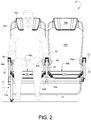
FIG. 2 is a front elevational view of a seat assembly depicted inFIG. 1 with a schematic representation of a passenger occupying one of the seats; -
FIG. 3 is side elevational view of the seat assembly depicted inFIG. 2 showing the spatial relationship with another similar seat assembly positioned in front at a nominal 28" seat pitch; -
FIG. 4 is a rear elevational view of the seat arrangement depicted inFIG. 3 ; -
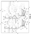
FIG. 5 is a top perspective view of the fore and aft seat arrangement depicted inFIG. 3 showing a representative passenger in each seat; -
FIGS. 6A-6C show the components of the seat bottom employed in the seat assemblies disclosed herein; -
FIG. 7 is a cross-sectional elevational view of the seat bottom employed in the seat assemblies disclosed herein; -
FIG. 8 is a detailed perspective cross-sectional view of the seat bottom construction employed in the seat assemblies disclosed herein; and -
FIG. 9 is a cross-sectional view of the seat backs of the seat assembly depicted inFIG. 1 as taken along line 9-9 therein in which some structure has been omitted (e.g., the arm rests) for clarity of presentation. - Accompanying
FIG. 1 shows a two-passenger seat assembly 10 in accordance with an embodiment of the invention disclosed herein. In this regard, theseat assembly 10 is depicted as being positioned on the port side of an aircraft cabin. A seat assembly which may be positioned on the starboard side of the aircraft cabin will thus be a mirror image of theassembly 10 depicted. Moreover, the seat assembly in accordance with the invention may also be embodied in a single, triple or more passenger seat arrangement if desired. - As shown in
FIGS. 1-5 , theseat assembly 10 includes an in inboard supportingbase 12 comprised of an uprightfront support leg 12a, an arcuaterear support 12b which has a lower end connected to the lower end of the front support leg and across-support 12c spanning the distance between the upper ends of thefront support leg 12a and therear support 12b. Arear leg 12d has an upper end connected to an intermediate position of thearcuate support 12b and extends rearwardly therefrom to allow for rigid connection to floor structure. - Forward and rearward substantially
horizontal support tubes rear supports cross-support 12c, respectively, and are rigidly connected to an intermediateupright support member 24 and anoutboard support member 16 that may be joined to structures associated with the passenger cabin (not shown). Abaggage guard 18 may be provided so as to extend below theforward support tube 14a from theforward support leg 12a to thesupport member 16. - An inboard
upright support member 20 has a lower end connected to the corner juncture between therear support 12b and the rear end of the cross-support 12c and extends upwardly therefrom. Similarly an outboardupright support member 22 is connected rigidly to a rear end of theinboard support member 16. Respective arm rests 30, 32 and 34 have a rear end pivotally connected to the upper end of theupper support members FIG. 1 . - The
seat assembly 10 includes a pair ofadjacent seats seat bottom seat bottoms horizontal support tubes knee protector band 44 is provided with opposed terminal ends formed into generallyU-shaped mounting clips 44a. The mountingclips 44a are connected to each of the lateral sides of the seat backs 42a, 42b in the lumbar region thereof and connected to eachupright support member U-shaped mounting clips 44a are therefore sized and configured to partially surround a portion of the upright tubular back frame 80 (seeFIG. 9 ) in adjacent the lumbar region of the seat backs 42a, 42b. This interconnection between theknee protector band 44 at the lumbar region of the seat backs 42a, 42b allows the lower portion thereof to remain positionally fixed but allow the upper portion to be flexed rearwardly (e.g., as depicted by the dashed line and arrow inFIG. 3 ) without the need for reclining mechanisms and their associated weight. - Concave
head rest assemblies brackets head rest assemblies head rest assemblies - The component structures associated with each of the
seat bottoms FIGS. 6A-6C andFIGS. 7-8 . In this regard, the discussion below in connection with such Figures will be with respect toseat bottom 40a, but it will be understood that such discussion is equally applicable to the structures associated withseat bottom 40b. - The
seat bottom 40a includes a recessedbasin 60 having abottom wall 62 and opposed front andrear walls bottom wall 62 and upwardly and outwardly extending therefrom. Each of the front andrear walls upper edges 62a-1, 62b-1, respectively. Thewalls basin 62 are preferably integral (unitary) with one another and formed of a lightweight material, e.g., a lightweight fiber-reinforced plastics material and/or lightweight metal (e.g., aluminum) alloy. Thebottom wall 62 of thebasin 60 thus forms a recessed interior region between theopposed end walls - Front and
rear support rods upper edges 62a-1, 62b-1 of theend walls support rods end eyelets rods bottom wall 62 of thebasin 60. - A relatively
thin fabric cushion 70 is positioned over the support straps 66. Thefabric cushion 70 includes front andrear flap regions lateral flap regions 70c each being joined to acentral cushion region 70d. The front andrear flap regions straps 66 while the opposedflap regions 70c extend over the lateral sides of thebasin 60 so as to cover lateral access to the interior recessed central region thereof. Thecentral seat region 70c is positioned over thestraps 66 and above the recessed central region of thebottom wall 62. Thefabric cushion 70 may be removably connected to thebasin 60 by any suitable connection devices, e.g., snap assemblies, hook assemblies, and fabric hook-and-pile connectors (e.g., VELCRO® fasteners) so as to positionally restrain thecushion 70 on thebasin 60. - As is shown in
FIG. 9 , each of the seat backs 42a, 42b is most preferably formed of an inverted U-shapedtubular back frame 80 and afabric sleeve 82 positioned over theback frame 80. Thefabric sleeve 82 is sized and configured so as to be held under tension laterally between the upright members of theback frame 80 so as to present a taut surface against which the passenger back may rest. Theback frame 80 is formed of a lightweight tubular material, e.g., a composite material, a lightweight fiber-reinforced plastics material and/or lightweight metal (e.g., aluminum) alloy. - Various modifications within the skill of those in the art may be envisioned. Therefore, while the invention has been described in connection with what is presently considered to be the most practical and preferred embodiment, it is to be understood that the invention is not to be limited to the disclosed embodiment, but on the contrary, is intended to cover various modifications and equivalent arrangements included within the spirit and scope thereof.
Claims (15)
- A vehicle passenger seat comprising:a seat back; anda seat bottom, wherein the seat bottom comprises:(i) a basin having a bottom wall and opposed end walls extending upwardly from the bottom wall to define therebetween a recessed central interior space;(ii) a plurality of straps having opposed ends connected to respective upper edge regions of the end walls so as to be positioned under tension over the recessed central interior space; and(iii) a cover cushion covering the straps and connected to the basin.
- The vehicle passenger seat according to claim 1, further comprising forward and rearward support rods each positioned transversely parallel to a respective upper edge region of the end walls of the basin, wherein the straps include eyelets at terminal ends thereof for receiving the support rod to thereby mount the straps to the basin under tension.
- The vehicle passenger seat according to claim 1 or 2, wherein the cover cushion include opposed side flaps and front and rear flaps each connected to the basin.
- The vehicle passenger seat according to one of the preceding claims, further comprising a support base for supporting the seat back and seat bottom, the support base comprising an upright front support leg having upper and lower ends and an arcuate rear support having upper and lower ends, wherein the lower end of the front support leg is connected to the lower end of the arcuate rear support.
- A vehicle passenger seat comprising:a seat back having a lumbar support region and an upper region above the lumbar support region which is capable of being resiliently flexed between upright and rearwardly inclined positions;a seat bottom,a support base supporting the seat back and seat bottom,a pair of upright support members connected to the support base and extending upwardly adjacent a respective lateral side of the seat back,a pair of generally U-shaped mounting clips which respectively interconnect the upright support members to the seat back at opposed sides thereof adjacent the lumbar region of the seat back.
- The vehicle passenger seat according to claim 4 or 5, wherein the support base comprises an upright front support leg having upper and lower ends and an arcuate rear support having upper and lower ends, wherein the lower end of the front support leg is connected to the lower end of the arcuate rear support.
- The vehicle passenger seat according to claim 4, 5, or 6, wherein the support base comprises a cross-support spanning a distance between and interconnecting the upper ends of the front support leg and the arcuate rear support.
- The vehicle passenger seat according to claim 7, further comprising forward and rearward substantially horizontal support tubes each extending laterally from respective interconnected upper ends of the front support leg and the arcuate rear support.
- The vehicle passenger seat according to one of claims 4 to 8, wherein the support base further comprises a rear leg connected to and rearwardly extending from the arcuate rear support.
- The vehicle passenger seat according to one of the preceding claims, wherein the seat back comprises a generally inverted U-shaped tubular seat back frame, and a fabric sleeve tautly covering the seat back frame.
- The vehicle passenger seat according to one of the preceding claims, further comprising a head rest removably attached to an upper end of the seat back.
- The vehicle passenger seat according to one of the preceding claims, further comprising a knee protector band connected to opposite lateral sides of the seat back adjacent a lumbar support region thereof.
- The vehicle passenger seat according to one of claims 1 to 11, further comprising a knee protector band which includes terminal ends formed into U-shaped mounting clips which partially surround the seat back frame at opposite lateral sides thereof adjacent the lumbar support region.
- The vehicle passenger seat according to one of the preceding claims, wherein the seat back frame allows an upper region of the seat back above a lumbar support region thereof to be resiliently flexed between upright and rearwardly inclined positions.
- An aircraft which comprises a passenger cabin and at least one vehicle passenger seat according to one of the preceding claims positioned within the passenger cabin.
Applications Claiming Priority (1)
| Application Number | Priority Date | Filing Date | Title |
|---|---|---|---|
| US201762575582P | 2017-10-23 | 2017-10-23 |
Publications (3)
| Publication Number | Publication Date |
|---|---|
| EP3473544A2 true EP3473544A2 (en) | 2019-04-24 |
| EP3473544A3 EP3473544A3 (en) | 2019-06-19 |
| EP3473544B1 EP3473544B1 (en) | 2023-10-04 |
Family
ID=63965362
Family Applications (1)
| Application Number | Title | Priority Date | Filing Date |
|---|---|---|---|
| EP18202003.2A Active EP3473544B1 (en) | 2017-10-23 | 2018-10-23 | Lightweight vehicle passenger seat assemblies |
Country Status (3)
| Country | Link |
|---|---|
| US (1) | US10766622B2 (en) |
| EP (1) | EP3473544B1 (en) |
| CN (1) | CN109693793A (en) |
Cited By (1)
| Publication number | Priority date | Publication date | Assignee | Title |
|---|---|---|---|---|
| US10669030B1 (en) * | 2019-04-23 | 2020-06-02 | B/E Aerospace, Inc. | Seat pan diaphragm |
Families Citing this family (7)
| Publication number | Priority date | Publication date | Assignee | Title |
|---|---|---|---|---|
| US11203434B2 (en) * | 2019-10-28 | 2021-12-21 | B/E Aersospace, Inc. | Diaphragm attachment method for aircraft seating |
| USD1014104S1 (en) * | 2020-08-31 | 2024-02-13 | Safran Seats Usa Llc | Passenger seat with a deployable privacy shield |
| US11958387B2 (en) | 2021-05-27 | 2024-04-16 | International Truck Intellectual Property Company, Llc | Seating in a vehicle |
| CN113749465A (en) * | 2021-10-13 | 2021-12-07 | 王建武 | An adaptive breathable pad |
| US11827363B2 (en) * | 2022-03-17 | 2023-11-28 | B/E Aerospace, Inc. | Composite seat bottom diaphragm |
| US12522362B2 (en) | 2022-03-17 | 2026-01-13 | B/E Aerospace, Inc. | Hybrid bottom seat cushion |
| FR3162727A1 (en) * | 2024-05-31 | 2025-12-05 | Safran | SEAT WITH AT LEAST ONE COMPOSITE STRUCTURE SEAT |
Citations (7)
| Publication number | Priority date | Publication date | Assignee | Title |
|---|---|---|---|---|
| US7954762B2 (en) | 2006-05-17 | 2011-06-07 | The Boeing Company | Lightweight aircraft passenger seat with composite construction |
| US8016361B2 (en) | 2006-12-22 | 2011-09-13 | The Boeing Company | Composite seat back structure for a lightweight aircraft seat assembly |
| US8020936B2 (en) | 2005-03-01 | 2011-09-20 | Koito Industries, Ltd. | Aircraft seat |
| US8047613B1 (en) | 2008-11-19 | 2011-11-01 | Timco Aviation Services, Inc. | Cushion-less aircraft seat |
| US8336965B2 (en) | 2006-12-22 | 2012-12-25 | The Boeing Company | Composite seat pan structure for a lightweight aircraft seat assembly |
| EP2162357B1 (en) | 2007-05-22 | 2013-12-11 | The Boeing Company | Modular passenger seat for an aircraft |
| US9327835B2 (en) | 2011-03-30 | 2016-05-03 | Expliseat | Airplane seat provided with a reinforcing strip for absorbing impacts |
Family Cites Families (47)
| Publication number | Priority date | Publication date | Assignee | Title |
|---|---|---|---|---|
| US2273273A (en) * | 1941-02-18 | 1942-02-17 | Kris Samuel | Resilient seat support |
| US2362585A (en) * | 1943-03-03 | 1944-11-14 | Robinson Harold | Chair construction |
| US2527635A (en) * | 1947-04-03 | 1950-10-31 | Iii Carroll B Hoffman | Chair having flexibly supported seat and back cushions |
| GB720696A (en) * | 1953-02-12 | 1954-12-22 | William Stevenson | Improvements in or relating to chairs, beds and the like |
| GB973731A (en) * | 1960-06-02 | 1964-10-28 | Microcell Ltd | Improvements in or relating to seats,chairs,chairbacks and the like |
| CA721090A (en) * | 1961-06-05 | 1965-11-09 | L. Propst Robert | Net seating |
| US3751110A (en) * | 1972-06-05 | 1973-08-07 | Lyon Shaw Inc | Strap fastening arrangement |
| JPS5377754A (en) * | 1976-12-20 | 1978-07-10 | Toyota Motor Co Ltd | Seat frame for vehicles |
| US4375300A (en) * | 1980-11-20 | 1983-03-01 | Uop Inc. | Framing system for aircraft passenger seat |
| DE3204540A1 (en) * | 1982-02-10 | 1983-08-18 | Peter 5000 Köln Backsmann | Back support, in particular for motor vehicle seats |
| US5485976A (en) * | 1994-01-12 | 1996-01-23 | Weber Aircraft, Inc. | Plastic bottom diaphragm for aircraft seat |
| FR2732565B1 (en) * | 1995-04-05 | 1997-06-13 | Fermob | FOLDING GARDEN SEAT |
| US5716101A (en) * | 1996-07-12 | 1998-02-10 | Bjip, Inc. | Seat rail attachment device |
| US5762403A (en) * | 1996-11-13 | 1998-06-09 | Woodard, Inc. | Sling type furniture product |
| US6231125B1 (en) * | 1997-12-26 | 2001-05-15 | Ts Tech Co., Ltd. | Seat with resilient sheet-formed seat cushion |
| US6357830B1 (en) * | 2000-01-18 | 2002-03-19 | Attwood Corporation | Shock absorbing seat |
| DE10012034A1 (en) * | 2000-03-03 | 2001-09-27 | Volkswagen Ag | Seat particularly for motor vehicle has cover formed from prestretchable plastic shrinkable by thermal action and with edge sections fitting in hollow profile of frame |
| US6663177B2 (en) * | 2000-12-13 | 2003-12-16 | Lear Corporation | Advanced elastomeric integral suspension seating system |
| DE10107197A1 (en) * | 2001-02-16 | 2002-10-02 | Recaro Aircraft Seating Gmbh | Vehicle seat, in particular passenger seat |
| US6474738B1 (en) * | 2001-06-20 | 2002-11-05 | Steelcase Development Corporation | Flip-up bolster chair |
| US6644738B2 (en) * | 2001-11-21 | 2003-11-11 | B E Aerospace, Inc. | Aircraft passenger seat frame construction |
| US7334845B2 (en) * | 2002-09-12 | 2008-02-26 | Steelcase Development Corporation | Comfort surface for seating |
| US7523988B1 (en) * | 2003-08-25 | 2009-04-28 | Milsco Manufacturing Company, A Unit Of Jason Incorporated | Seat, suspension, bolster and shell |
| JP4554438B2 (en) * | 2004-12-28 | 2010-09-29 | 株式会社デルタツーリング | Lumber support, seat cushion and seat structure |
| US20070102987A1 (en) * | 2005-11-04 | 2007-05-10 | Su-Ming Chen | Meshed seat cushion for chair |
| US20070200414A1 (en) * | 2006-02-27 | 2007-08-30 | Pozzi Alexander N | Vehicle seats and components thereof |
| US20080106136A1 (en) * | 2006-04-28 | 2008-05-08 | Heidmann Kurt R | Seat front edge construction |
| AT505223A1 (en) * | 2007-04-13 | 2008-11-15 | Greiner Purtec Gmbh | SEAT, ESPECIALLY FOR PUBLIC TRANSPORT |
| US7533930B1 (en) * | 2007-10-24 | 2009-05-19 | Embraer - Empresa Brasileira De Aeronautica S.A. | Convertible aircraft passenger seat and method |
| FR2934821B1 (en) * | 2008-08-07 | 2010-12-24 | Tachi S Co | DEVICE FOR RETAINING A SEAT ELBOW ELEMENT OF A MOTOR VEHICLE. |
| JP5387390B2 (en) * | 2009-12-25 | 2014-01-15 | トヨタ車体株式会社 | Vehicle seat |
| DE102010018822B4 (en) * | 2010-04-29 | 2016-03-24 | Grammer Aktiengesellschaft | Weatherproof seat for recreational vehicles |
| EP2709873B1 (en) * | 2011-05-20 | 2020-07-08 | Zodiac Seats France | Kinematic seat with elastic pivot |
| CN105946672B (en) * | 2011-09-25 | 2018-08-17 | 提爱思科技股份有限公司 | Device for vehicle seat |
| JP6026634B2 (en) * | 2012-03-14 | 2016-11-16 | ビーイー・エアロスペース・インコーポレーテッドB/E Aerospace, Inc. | Integrally molded seat back and method for composite seat frames |
| JP6204358B2 (en) * | 2012-08-07 | 2017-09-27 | テイ・エス テック株式会社 | Vehicle seat |
| CN202896582U (en) * | 2012-10-22 | 2013-04-24 | 今创集团股份有限公司 | Adjustable seat |
| JP6094273B2 (en) * | 2013-03-06 | 2017-03-15 | トヨタ紡織株式会社 | Vehicle seat |
| DE102013103436B4 (en) * | 2013-04-05 | 2018-10-11 | Recaro Aircraft Seating Gmbh & Co. Kg | Seat device and seat, in particular aircraft seat, with a seat device |
| CN103465814B (en) * | 2013-09-23 | 2016-01-20 | 上海延锋江森座椅有限公司 | Three-point type safety belt seat frame structure |
| US9919803B2 (en) * | 2014-04-04 | 2018-03-20 | B/E Aerospace, Inc. | Aircraft seat base frame |
| CN106314239A (en) * | 2015-06-26 | 2017-01-11 | 上汽通用五菱汽车股份有限公司 | Back row seat framework structure |
| US9751438B2 (en) * | 2015-08-19 | 2017-09-05 | Marlow Gene Dunham | Seat resting apparatus |
| DE102016102707A1 (en) * | 2016-02-16 | 2017-08-17 | Recaro Aircraft Seating Gmbh & Co. Kg | Aircraft seat device |
| CN205686220U (en) * | 2016-06-13 | 2016-11-16 | 宁波泰尔汽车部件有限公司 | A kind of bus seat of the knee that can protect human body |
| US10144323B2 (en) * | 2017-01-31 | 2018-12-04 | Ford Global Technologies, Llc | Vehicle seating assembly having abrasion resistant slip cover |
| DE102017122252A1 (en) * | 2017-09-26 | 2019-03-28 | Airbus Operations Gmbh | Passenger seating arrangement, passenger seating system and method of installing a passenger seating system |
-
2018
- 2018-10-22 US US16/166,514 patent/US10766622B2/en active Active
- 2018-10-23 EP EP18202003.2A patent/EP3473544B1/en active Active
- 2018-10-23 CN CN201811235932.9A patent/CN109693793A/en active Pending
Patent Citations (8)
| Publication number | Priority date | Publication date | Assignee | Title |
|---|---|---|---|---|
| US8020936B2 (en) | 2005-03-01 | 2011-09-20 | Koito Industries, Ltd. | Aircraft seat |
| US7954762B2 (en) | 2006-05-17 | 2011-06-07 | The Boeing Company | Lightweight aircraft passenger seat with composite construction |
| US8016361B2 (en) | 2006-12-22 | 2011-09-13 | The Boeing Company | Composite seat back structure for a lightweight aircraft seat assembly |
| US8336965B2 (en) | 2006-12-22 | 2012-12-25 | The Boeing Company | Composite seat pan structure for a lightweight aircraft seat assembly |
| EP2162357B1 (en) | 2007-05-22 | 2013-12-11 | The Boeing Company | Modular passenger seat for an aircraft |
| US8047613B1 (en) | 2008-11-19 | 2011-11-01 | Timco Aviation Services, Inc. | Cushion-less aircraft seat |
| US8596723B2 (en) | 2008-11-19 | 2013-12-03 | Timco Aviation Services, Inc. | Cushion-less aircraft seat |
| US9327835B2 (en) | 2011-03-30 | 2016-05-03 | Expliseat | Airplane seat provided with a reinforcing strip for absorbing impacts |
Cited By (1)
| Publication number | Priority date | Publication date | Assignee | Title |
|---|---|---|---|---|
| US10669030B1 (en) * | 2019-04-23 | 2020-06-02 | B/E Aerospace, Inc. | Seat pan diaphragm |
Also Published As
| Publication number | Publication date |
|---|---|
| US10766622B2 (en) | 2020-09-08 |
| US20190118951A1 (en) | 2019-04-25 |
| CN109693793A (en) | 2019-04-30 |
| BR102018071709A2 (en) | 2019-08-06 |
| EP3473544A3 (en) | 2019-06-19 |
| EP3473544B1 (en) | 2023-10-04 |
Similar Documents
| Publication | Publication Date | Title |
|---|---|---|
| US10766622B2 (en) | Lightweight vehicle passenger seat assemblies | |
| US7055904B2 (en) | Vehicle seating adapted for sleeping posture | |
| JP5209605B2 (en) | Passenger seat arrangement | |
| EP2272711B2 (en) | A seat unit for a passenger vehicle | |
| EP1699682B1 (en) | Frame assembly for vehicle passenger seat | |
| EP1916925B1 (en) | Lounge seating arrangement | |
| US7131698B2 (en) | Vehicle passenger seat with adjustable headrest | |
| US20160376007A1 (en) | Aircraft Seat with Seating and Reclining Positions | |
| US20110186682A1 (en) | Seat module for an aircraft passenger | |
| JP2008544927A (en) | Transportation seating arrangement | |
| JP2009534248A5 (en) | ||
| EP3901041B1 (en) | Vertically stowed padded tray table for passenger seat | |
| EP2981459B1 (en) | Sidewall integrated armrest for aircraft interiors | |
| WO2018169575A1 (en) | Passenger seat with movable backrest portion | |
| JP2014184953A (en) | Constitution of seat convertible into bed | |
| EP3566946B1 (en) | Seat assembly having a deployable headrest | |
| WO2011053679A1 (en) | Seat pan drop down link | |
| US20250187734A1 (en) | Vehicle suite seating arrangement | |
| CN110506004A (en) | With the passenger seat being comfortably laid out | |
| EP2905226A1 (en) | Passenger seat for an aircraft | |
| US20050151405A1 (en) | Vehicle seating with protected living space | |
| US11241978B2 (en) | Passenger transport seats with lateral seat lips | |
| BR102018071709B1 (en) | LIGHT VEHICLE PASSENGER SEAT MOUNTS | |
| JP2024127845A (en) | Vehicle seats | |
| HK1154831B (en) | A seating system and a passenger seat unit for an aircraft |
Legal Events
| Date | Code | Title | Description |
|---|---|---|---|
| PUAI | Public reference made under article 153(3) epc to a published international application that has entered the european phase |
Free format text: ORIGINAL CODE: 0009012 |
|
| STAA | Information on the status of an ep patent application or granted ep patent |
Free format text: STATUS: THE APPLICATION HAS BEEN PUBLISHED |
|
| AK | Designated contracting states |
Kind code of ref document: A2 Designated state(s): AL AT BE BG CH CY CZ DE DK EE ES FI FR GB GR HR HU IE IS IT LI LT LU LV MC MK MT NL NO PL PT RO RS SE SI SK SM TR |
|
| AX | Request for extension of the european patent |
Extension state: BA ME |
|
| PUAL | Search report despatched |
Free format text: ORIGINAL CODE: 0009013 |
|
| AK | Designated contracting states |
Kind code of ref document: A3 Designated state(s): AL AT BE BG CH CY CZ DE DK EE ES FI FR GB GR HR HU IE IS IT LI LT LU LV MC MK MT NL NO PL PT RO RS SE SI SK SM TR |
|
| AX | Request for extension of the european patent |
Extension state: BA ME |
|
| RIC1 | Information provided on ipc code assigned before grant |
Ipc: B64D 11/06 20060101AFI20190516BHEP Ipc: B60N 2/00 20060101ALI20190516BHEP |
|
| RIN1 | Information on inventor provided before grant (corrected) |
Inventor name: DE CAMPOS, DEMETRIO ANDRADE Inventor name: ABELHEIRA, RICARDO ATHAYDE Inventor name: KAWASAKI, RODRIGO TAKASHI LOURENCO Inventor name: DE ANDRADE LIMA, MOACIR MORAIS Inventor name: CIACCIA, FLAVIA RENATA DANTAS ALVES SILVA Inventor name: DA SILVA, FABIO SANTOS Inventor name: DECARLI, FABIANO MAFRA |
|
| STAA | Information on the status of an ep patent application or granted ep patent |
Free format text: STATUS: REQUEST FOR EXAMINATION WAS MADE |
|
| 17P | Request for examination filed |
Effective date: 20191210 |
|
| RBV | Designated contracting states (corrected) |
Designated state(s): AL AT BE BG CH CY CZ DE DK EE ES FI FR GB GR HR HU IE IS IT LI LT LU LV MC MK MT NL NO PL PT RO RS SE SI SK SM TR |
|
| STAA | Information on the status of an ep patent application or granted ep patent |
Free format text: STATUS: EXAMINATION IS IN PROGRESS |
|
| RAP1 | Party data changed (applicant data changed or rights of an application transferred) |
Owner name: YABORA INDUSTRIA AERONAUTICA S.A. |
|
| 17Q | First examination report despatched |
Effective date: 20200422 |
|
| GRAP | Despatch of communication of intention to grant a patent |
Free format text: ORIGINAL CODE: EPIDOSNIGR1 |
|
| STAA | Information on the status of an ep patent application or granted ep patent |
Free format text: STATUS: GRANT OF PATENT IS INTENDED |
|
| RIC1 | Information provided on ipc code assigned before grant |
Ipc: B60N 2/72 20060101ALI20230516BHEP Ipc: B60N 2/75 20180101ALI20230516BHEP Ipc: B60N 2/42 20060101ALI20230516BHEP Ipc: B60N 2/70 20060101ALI20230516BHEP Ipc: B60N 2/24 20060101ALI20230516BHEP Ipc: B64D 11/06 20060101AFI20230516BHEP |
|
| INTG | Intention to grant announced |
Effective date: 20230605 |
|
| GRAS | Grant fee paid |
Free format text: ORIGINAL CODE: EPIDOSNIGR3 |
|
| GRAA | (expected) grant |
Free format text: ORIGINAL CODE: 0009210 |
|
| STAA | Information on the status of an ep patent application or granted ep patent |
Free format text: STATUS: THE PATENT HAS BEEN GRANTED |
|
| AK | Designated contracting states |
Kind code of ref document: B1 Designated state(s): AL AT BE BG CH CY CZ DE DK EE ES FI FR GB GR HR HU IE IS IT LI LT LU LV MC MK MT NL NO PL PT RO RS SE SI SK SM TR |
|
| REG | Reference to a national code |
Ref country code: GB Ref legal event code: FG4D |
|
| REG | Reference to a national code |
Ref country code: CH Ref legal event code: EP |
|
| REG | Reference to a national code |
Ref country code: IE Ref legal event code: FG4D |
|
| REG | Reference to a national code |
Ref country code: DE Ref legal event code: R096 Ref document number: 602018058572 Country of ref document: DE |
|
| REG | Reference to a national code |
Ref country code: LT Ref legal event code: MG9D |
|
| REG | Reference to a national code |
Ref country code: NL Ref legal event code: MP Effective date: 20231004 |
|
| REG | Reference to a national code |
Ref country code: AT Ref legal event code: MK05 Ref document number: 1617536 Country of ref document: AT Kind code of ref document: T Effective date: 20231004 |
|
| PG25 | Lapsed in a contracting state [announced via postgrant information from national office to epo] |
Ref country code: NL Free format text: LAPSE BECAUSE OF FAILURE TO SUBMIT A TRANSLATION OF THE DESCRIPTION OR TO PAY THE FEE WITHIN THE PRESCRIBED TIME-LIMIT Effective date: 20231004 |
|
| PG25 | Lapsed in a contracting state [announced via postgrant information from national office to epo] |
Ref country code: IS Free format text: LAPSE BECAUSE OF FAILURE TO SUBMIT A TRANSLATION OF THE DESCRIPTION OR TO PAY THE FEE WITHIN THE PRESCRIBED TIME-LIMIT Effective date: 20240204 |
|
| PG25 | Lapsed in a contracting state [announced via postgrant information from national office to epo] |
Ref country code: LT Free format text: LAPSE BECAUSE OF FAILURE TO SUBMIT A TRANSLATION OF THE DESCRIPTION OR TO PAY THE FEE WITHIN THE PRESCRIBED TIME-LIMIT Effective date: 20231004 |
|
| PG25 | Lapsed in a contracting state [announced via postgrant information from national office to epo] |
Ref country code: AT Free format text: LAPSE BECAUSE OF FAILURE TO SUBMIT A TRANSLATION OF THE DESCRIPTION OR TO PAY THE FEE WITHIN THE PRESCRIBED TIME-LIMIT Effective date: 20231004 |
|
| PG25 | Lapsed in a contracting state [announced via postgrant information from national office to epo] |
Ref country code: ES Free format text: LAPSE BECAUSE OF FAILURE TO SUBMIT A TRANSLATION OF THE DESCRIPTION OR TO PAY THE FEE WITHIN THE PRESCRIBED TIME-LIMIT Effective date: 20231004 |
|
| PG25 | Lapsed in a contracting state [announced via postgrant information from national office to epo] |
Ref country code: LT Free format text: LAPSE BECAUSE OF FAILURE TO SUBMIT A TRANSLATION OF THE DESCRIPTION OR TO PAY THE FEE WITHIN THE PRESCRIBED TIME-LIMIT Effective date: 20231004 Ref country code: IS Free format text: LAPSE BECAUSE OF FAILURE TO SUBMIT A TRANSLATION OF THE DESCRIPTION OR TO PAY THE FEE WITHIN THE PRESCRIBED TIME-LIMIT Effective date: 20240204 Ref country code: ES Free format text: LAPSE BECAUSE OF FAILURE TO SUBMIT A TRANSLATION OF THE DESCRIPTION OR TO PAY THE FEE WITHIN THE PRESCRIBED TIME-LIMIT Effective date: 20231004 Ref country code: BG Free format text: LAPSE BECAUSE OF FAILURE TO SUBMIT A TRANSLATION OF THE DESCRIPTION OR TO PAY THE FEE WITHIN THE PRESCRIBED TIME-LIMIT Effective date: 20240104 Ref country code: AT Free format text: LAPSE BECAUSE OF FAILURE TO SUBMIT A TRANSLATION OF THE DESCRIPTION OR TO PAY THE FEE WITHIN THE PRESCRIBED TIME-LIMIT Effective date: 20231004 Ref country code: PT Free format text: LAPSE BECAUSE OF FAILURE TO SUBMIT A TRANSLATION OF THE DESCRIPTION OR TO PAY THE FEE WITHIN THE PRESCRIBED TIME-LIMIT Effective date: 20240205 |
|
| REG | Reference to a national code |
Ref country code: DE Ref legal event code: R119 Ref document number: 602018058572 Country of ref document: DE |
|
| PG25 | Lapsed in a contracting state [announced via postgrant information from national office to epo] |
Ref country code: SE Free format text: LAPSE BECAUSE OF FAILURE TO SUBMIT A TRANSLATION OF THE DESCRIPTION OR TO PAY THE FEE WITHIN THE PRESCRIBED TIME-LIMIT Effective date: 20231004 Ref country code: RS Free format text: LAPSE BECAUSE OF FAILURE TO SUBMIT A TRANSLATION OF THE DESCRIPTION OR TO PAY THE FEE WITHIN THE PRESCRIBED TIME-LIMIT Effective date: 20231004 Ref country code: PL Free format text: LAPSE BECAUSE OF FAILURE TO SUBMIT A TRANSLATION OF THE DESCRIPTION OR TO PAY THE FEE WITHIN THE PRESCRIBED TIME-LIMIT Effective date: 20231004 Ref country code: NO Free format text: LAPSE BECAUSE OF FAILURE TO SUBMIT A TRANSLATION OF THE DESCRIPTION OR TO PAY THE FEE WITHIN THE PRESCRIBED TIME-LIMIT Effective date: 20240104 Ref country code: LV Free format text: LAPSE BECAUSE OF FAILURE TO SUBMIT A TRANSLATION OF THE DESCRIPTION OR TO PAY THE FEE WITHIN THE PRESCRIBED TIME-LIMIT Effective date: 20231004 Ref country code: HR Free format text: LAPSE BECAUSE OF FAILURE TO SUBMIT A TRANSLATION OF THE DESCRIPTION OR TO PAY THE FEE WITHIN THE PRESCRIBED TIME-LIMIT Effective date: 20231004 |
|
| REG | Reference to a national code |
Ref country code: CH Ref legal event code: PL |
|
| REG | Reference to a national code |
Ref country code: BE Ref legal event code: MM Effective date: 20231031 |
|
| PG25 | Lapsed in a contracting state [announced via postgrant information from national office to epo] |
Ref country code: LU Free format text: LAPSE BECAUSE OF NON-PAYMENT OF DUE FEES Effective date: 20231023 |
|
| PG25 | Lapsed in a contracting state [announced via postgrant information from national office to epo] |
Ref country code: LU Free format text: LAPSE BECAUSE OF NON-PAYMENT OF DUE FEES Effective date: 20231023 |
|
| PG25 | Lapsed in a contracting state [announced via postgrant information from national office to epo] |
Ref country code: DK Free format text: LAPSE BECAUSE OF FAILURE TO SUBMIT A TRANSLATION OF THE DESCRIPTION OR TO PAY THE FEE WITHIN THE PRESCRIBED TIME-LIMIT Effective date: 20231004 |
|
| PG25 | Lapsed in a contracting state [announced via postgrant information from national office to epo] |
Ref country code: CH Free format text: LAPSE BECAUSE OF NON-PAYMENT OF DUE FEES Effective date: 20231031 |
|
| PG25 | Lapsed in a contracting state [announced via postgrant information from national office to epo] |
Ref country code: CZ Free format text: LAPSE BECAUSE OF FAILURE TO SUBMIT A TRANSLATION OF THE DESCRIPTION OR TO PAY THE FEE WITHIN THE PRESCRIBED TIME-LIMIT Effective date: 20231004 |
|
| PG25 | Lapsed in a contracting state [announced via postgrant information from national office to epo] |
Ref country code: SK Free format text: LAPSE BECAUSE OF FAILURE TO SUBMIT A TRANSLATION OF THE DESCRIPTION OR TO PAY THE FEE WITHIN THE PRESCRIBED TIME-LIMIT Effective date: 20231004 |
|
| PG25 | Lapsed in a contracting state [announced via postgrant information from national office to epo] |
Ref country code: SM Free format text: LAPSE BECAUSE OF FAILURE TO SUBMIT A TRANSLATION OF THE DESCRIPTION OR TO PAY THE FEE WITHIN THE PRESCRIBED TIME-LIMIT Effective date: 20231004 Ref country code: SK Free format text: LAPSE BECAUSE OF FAILURE TO SUBMIT A TRANSLATION OF THE DESCRIPTION OR TO PAY THE FEE WITHIN THE PRESCRIBED TIME-LIMIT Effective date: 20231004 Ref country code: RO Free format text: LAPSE BECAUSE OF FAILURE TO SUBMIT A TRANSLATION OF THE DESCRIPTION OR TO PAY THE FEE WITHIN THE PRESCRIBED TIME-LIMIT Effective date: 20231004 Ref country code: IT Free format text: LAPSE BECAUSE OF FAILURE TO SUBMIT A TRANSLATION OF THE DESCRIPTION OR TO PAY THE FEE WITHIN THE PRESCRIBED TIME-LIMIT Effective date: 20231004 Ref country code: EE Free format text: LAPSE BECAUSE OF FAILURE TO SUBMIT A TRANSLATION OF THE DESCRIPTION OR TO PAY THE FEE WITHIN THE PRESCRIBED TIME-LIMIT Effective date: 20231004 Ref country code: DK Free format text: LAPSE BECAUSE OF FAILURE TO SUBMIT A TRANSLATION OF THE DESCRIPTION OR TO PAY THE FEE WITHIN THE PRESCRIBED TIME-LIMIT Effective date: 20231004 Ref country code: DE Free format text: LAPSE BECAUSE OF NON-PAYMENT OF DUE FEES Effective date: 20240501 Ref country code: CZ Free format text: LAPSE BECAUSE OF FAILURE TO SUBMIT A TRANSLATION OF THE DESCRIPTION OR TO PAY THE FEE WITHIN THE PRESCRIBED TIME-LIMIT Effective date: 20231004 Ref country code: CH Free format text: LAPSE BECAUSE OF NON-PAYMENT OF DUE FEES Effective date: 20231031 |
|
| PLBE | No opposition filed within time limit |
Free format text: ORIGINAL CODE: 0009261 |
|
| STAA | Information on the status of an ep patent application or granted ep patent |
Free format text: STATUS: NO OPPOSITION FILED WITHIN TIME LIMIT |
|
| PG25 | Lapsed in a contracting state [announced via postgrant information from national office to epo] |
Ref country code: MC Free format text: LAPSE BECAUSE OF FAILURE TO SUBMIT A TRANSLATION OF THE DESCRIPTION OR TO PAY THE FEE WITHIN THE PRESCRIBED TIME-LIMIT Effective date: 20231004 |
|
| PG25 | Lapsed in a contracting state [announced via postgrant information from national office to epo] |
Ref country code: MC Free format text: LAPSE BECAUSE OF FAILURE TO SUBMIT A TRANSLATION OF THE DESCRIPTION OR TO PAY THE FEE WITHIN THE PRESCRIBED TIME-LIMIT Effective date: 20231004 Ref country code: BE Free format text: LAPSE BECAUSE OF NON-PAYMENT OF DUE FEES Effective date: 20231031 |
|
| 26N | No opposition filed |
Effective date: 20240705 |
|
| PG25 | Lapsed in a contracting state [announced via postgrant information from national office to epo] |
Ref country code: IE Free format text: LAPSE BECAUSE OF NON-PAYMENT OF DUE FEES Effective date: 20231023 |
|
| PG25 | Lapsed in a contracting state [announced via postgrant information from national office to epo] |
Ref country code: FR Free format text: LAPSE BECAUSE OF NON-PAYMENT OF DUE FEES Effective date: 20231204 |
|
| PG25 | Lapsed in a contracting state [announced via postgrant information from national office to epo] |
Ref country code: SI Free format text: LAPSE BECAUSE OF FAILURE TO SUBMIT A TRANSLATION OF THE DESCRIPTION OR TO PAY THE FEE WITHIN THE PRESCRIBED TIME-LIMIT Effective date: 20231004 |
|
| PG25 | Lapsed in a contracting state [announced via postgrant information from national office to epo] |
Ref country code: SI Free format text: LAPSE BECAUSE OF FAILURE TO SUBMIT A TRANSLATION OF THE DESCRIPTION OR TO PAY THE FEE WITHIN THE PRESCRIBED TIME-LIMIT Effective date: 20231004 Ref country code: IE Free format text: LAPSE BECAUSE OF NON-PAYMENT OF DUE FEES Effective date: 20231023 Ref country code: FR Free format text: LAPSE BECAUSE OF NON-PAYMENT OF DUE FEES Effective date: 20231204 |
|
| PG25 | Lapsed in a contracting state [announced via postgrant information from national office to epo] |
Ref country code: FI Free format text: LAPSE BECAUSE OF FAILURE TO SUBMIT A TRANSLATION OF THE DESCRIPTION OR TO PAY THE FEE WITHIN THE PRESCRIBED TIME-LIMIT Effective date: 20231004 |
|
| PG25 | Lapsed in a contracting state [announced via postgrant information from national office to epo] |
Ref country code: CY Free format text: LAPSE BECAUSE OF FAILURE TO SUBMIT A TRANSLATION OF THE DESCRIPTION OR TO PAY THE FEE WITHIN THE PRESCRIBED TIME-LIMIT; INVALID AB INITIO Effective date: 20181023 |
|
| PG25 | Lapsed in a contracting state [announced via postgrant information from national office to epo] |
Ref country code: HU Free format text: LAPSE BECAUSE OF FAILURE TO SUBMIT A TRANSLATION OF THE DESCRIPTION OR TO PAY THE FEE WITHIN THE PRESCRIBED TIME-LIMIT; INVALID AB INITIO Effective date: 20181023 |
|
| PG25 | Lapsed in a contracting state [announced via postgrant information from national office to epo] |
Ref country code: GR Free format text: LAPSE BECAUSE OF FAILURE TO SUBMIT A TRANSLATION OF THE DESCRIPTION OR TO PAY THE FEE WITHIN THE PRESCRIBED TIME-LIMIT; INVALID AB INITIO Effective date: 20181023 |
|
| PG25 | Lapsed in a contracting state [announced via postgrant information from national office to epo] |
Ref country code: TR Free format text: LAPSE BECAUSE OF FAILURE TO SUBMIT A TRANSLATION OF THE DESCRIPTION OR TO PAY THE FEE WITHIN THE PRESCRIBED TIME-LIMIT Effective date: 20231004 |
|
| PGFP | Annual fee paid to national office [announced via postgrant information from national office to epo] |
Ref country code: GB Payment date: 20251027 Year of fee payment: 8 |