EP3473541B1 - Cale de barrette de roue freinée d'aéronef - Google Patents
Cale de barrette de roue freinée d'aéronef Download PDFInfo
- Publication number
- EP3473541B1 EP3473541B1 EP18201074.4A EP18201074A EP3473541B1 EP 3473541 B1 EP3473541 B1 EP 3473541B1 EP 18201074 A EP18201074 A EP 18201074A EP 3473541 B1 EP3473541 B1 EP 3473541B1
- Authority
- EP
- European Patent Office
- Prior art keywords
- bar
- spacer
- rim
- voids
- wedge
- Prior art date
- Legal status (The legal status is an assumption and is not a legal conclusion. Google has not performed a legal analysis and makes no representation as to the accuracy of the status listed.)
- Active
Links
Images





Classifications
-
- F—MECHANICAL ENGINEERING; LIGHTING; HEATING; WEAPONS; BLASTING
- F16—ENGINEERING ELEMENTS AND UNITS; GENERAL MEASURES FOR PRODUCING AND MAINTAINING EFFECTIVE FUNCTIONING OF MACHINES OR INSTALLATIONS; THERMAL INSULATION IN GENERAL
- F16D—COUPLINGS FOR TRANSMITTING ROTATION; CLUTCHES; BRAKES
- F16D65/00—Parts or details
- F16D65/005—Components of axially engaging brakes not otherwise provided for
- F16D65/0056—Brake supports
-
- B—PERFORMING OPERATIONS; TRANSPORTING
- B29—WORKING OF PLASTICS; WORKING OF SUBSTANCES IN A PLASTIC STATE IN GENERAL
- B29C—SHAPING OR JOINING OF PLASTICS; SHAPING OF MATERIAL IN A PLASTIC STATE, NOT OTHERWISE PROVIDED FOR; AFTER-TREATMENT OF THE SHAPED PRODUCTS, e.g. REPAIRING
- B29C64/00—Additive manufacturing, i.e. manufacturing of three-dimensional [3D] objects by additive deposition, additive agglomeration or additive layering, e.g. by 3D printing, stereolithography or selective laser sintering
- B29C64/10—Processes of additive manufacturing
- B29C64/141—Processes of additive manufacturing using only solid materials
- B29C64/153—Processes of additive manufacturing using only solid materials using layers of powder being selectively joined, e.g. by selective laser sintering or melting
-
- B—PERFORMING OPERATIONS; TRANSPORTING
- B60—VEHICLES IN GENERAL
- B60T—VEHICLE BRAKE CONTROL SYSTEMS OR PARTS THEREOF; BRAKE CONTROL SYSTEMS OR PARTS THEREOF, IN GENERAL; ARRANGEMENT OF BRAKING ELEMENTS ON VEHICLES IN GENERAL; PORTABLE DEVICES FOR PREVENTING UNWANTED MOVEMENT OF VEHICLES; VEHICLE MODIFICATIONS TO FACILITATE COOLING OF BRAKES
- B60T1/00—Arrangements of braking elements, i.e. of those parts where braking effect occurs specially for vehicles
- B60T1/02—Arrangements of braking elements, i.e. of those parts where braking effect occurs specially for vehicles acting by retarding wheels
- B60T1/06—Arrangements of braking elements, i.e. of those parts where braking effect occurs specially for vehicles acting by retarding wheels acting otherwise than on tread, e.g. employing rim, drum, disc, or transmission or on double wheels
- B60T1/062—Arrangements of braking elements, i.e. of those parts where braking effect occurs specially for vehicles acting by retarding wheels acting otherwise than on tread, e.g. employing rim, drum, disc, or transmission or on double wheels acting on transmission parts
-
- B—PERFORMING OPERATIONS; TRANSPORTING
- B64—AIRCRAFT; AVIATION; COSMONAUTICS
- B64C—AEROPLANES; HELICOPTERS
- B64C25/00—Alighting gear
- B64C25/32—Alighting gear characterised by elements which contact the ground or similar surface
- B64C25/42—Arrangement or adaptation of brakes
-
- F—MECHANICAL ENGINEERING; LIGHTING; HEATING; WEAPONS; BLASTING
- F16—ENGINEERING ELEMENTS AND UNITS; GENERAL MEASURES FOR PRODUCING AND MAINTAINING EFFECTIVE FUNCTIONING OF MACHINES OR INSTALLATIONS; THERMAL INSULATION IN GENERAL
- F16B—DEVICES FOR FASTENING OR SECURING CONSTRUCTIONAL ELEMENTS OR MACHINE PARTS TOGETHER, e.g. NAILS, BOLTS, CIRCLIPS, CLAMPS, CLIPS OR WEDGES; JOINTS OR JOINTING
- F16B43/00—Washers or equivalent devices; Other devices for supporting bolt-heads or nuts
- F16B43/001—Washers or equivalent devices; Other devices for supporting bolt-heads or nuts for sealing or insulation
-
- F—MECHANICAL ENGINEERING; LIGHTING; HEATING; WEAPONS; BLASTING
- F16—ENGINEERING ELEMENTS AND UNITS; GENERAL MEASURES FOR PRODUCING AND MAINTAINING EFFECTIVE FUNCTIONING OF MACHINES OR INSTALLATIONS; THERMAL INSULATION IN GENERAL
- F16B—DEVICES FOR FASTENING OR SECURING CONSTRUCTIONAL ELEMENTS OR MACHINE PARTS TOGETHER, e.g. NAILS, BOLTS, CIRCLIPS, CLAMPS, CLIPS OR WEDGES; JOINTS OR JOINTING
- F16B43/00—Washers or equivalent devices; Other devices for supporting bolt-heads or nuts
- F16B43/02—Washers or equivalent devices; Other devices for supporting bolt-heads or nuts with special provisions for engaging surfaces which are not perpendicular to a bolt axis or do not surround the bolt
-
- F—MECHANICAL ENGINEERING; LIGHTING; HEATING; WEAPONS; BLASTING
- F16—ENGINEERING ELEMENTS AND UNITS; GENERAL MEASURES FOR PRODUCING AND MAINTAINING EFFECTIVE FUNCTIONING OF MACHINES OR INSTALLATIONS; THERMAL INSULATION IN GENERAL
- F16D—COUPLINGS FOR TRANSMITTING ROTATION; CLUTCHES; BRAKES
- F16D55/00—Brakes with substantially-radial braking surfaces pressed together in axial direction, e.g. disc brakes
- F16D55/24—Brakes with substantially-radial braking surfaces pressed together in axial direction, e.g. disc brakes with a plurality of axially-movable discs, lamellae, or pads, pressed from one side towards an axially-located member
- F16D55/26—Brakes with substantially-radial braking surfaces pressed together in axial direction, e.g. disc brakes with a plurality of axially-movable discs, lamellae, or pads, pressed from one side towards an axially-located member without self-tightening action
- F16D55/36—Brakes with a plurality of rotating discs all lying side by side
-
- F—MECHANICAL ENGINEERING; LIGHTING; HEATING; WEAPONS; BLASTING
- F16—ENGINEERING ELEMENTS AND UNITS; GENERAL MEASURES FOR PRODUCING AND MAINTAINING EFFECTIVE FUNCTIONING OF MACHINES OR INSTALLATIONS; THERMAL INSULATION IN GENERAL
- F16D—COUPLINGS FOR TRANSMITTING ROTATION; CLUTCHES; BRAKES
- F16D65/00—Parts or details
- F16D65/02—Braking members; Mounting thereof
-
- F—MECHANICAL ENGINEERING; LIGHTING; HEATING; WEAPONS; BLASTING
- F16—ENGINEERING ELEMENTS AND UNITS; GENERAL MEASURES FOR PRODUCING AND MAINTAINING EFFECTIVE FUNCTIONING OF MACHINES OR INSTALLATIONS; THERMAL INSULATION IN GENERAL
- F16D—COUPLINGS FOR TRANSMITTING ROTATION; CLUTCHES; BRAKES
- F16D65/00—Parts or details
- F16D65/02—Braking members; Mounting thereof
- F16D65/04—Bands, shoes or pads; Pivots or supporting members therefor
- F16D65/092—Bands, shoes or pads; Pivots or supporting members therefor for axially-engaging brakes, e.g. disc brakes
-
- F—MECHANICAL ENGINEERING; LIGHTING; HEATING; WEAPONS; BLASTING
- F16—ENGINEERING ELEMENTS AND UNITS; GENERAL MEASURES FOR PRODUCING AND MAINTAINING EFFECTIVE FUNCTIONING OF MACHINES OR INSTALLATIONS; THERMAL INSULATION IN GENERAL
- F16D—COUPLINGS FOR TRANSMITTING ROTATION; CLUTCHES; BRAKES
- F16D65/00—Parts or details
- F16D65/02—Braking members; Mounting thereof
- F16D65/04—Bands, shoes or pads; Pivots or supporting members therefor
- F16D65/092—Bands, shoes or pads; Pivots or supporting members therefor for axially-engaging brakes, e.g. disc brakes
- F16D65/095—Pivots or supporting members therefor
-
- F—MECHANICAL ENGINEERING; LIGHTING; HEATING; WEAPONS; BLASTING
- F16—ENGINEERING ELEMENTS AND UNITS; GENERAL MEASURES FOR PRODUCING AND MAINTAINING EFFECTIVE FUNCTIONING OF MACHINES OR INSTALLATIONS; THERMAL INSULATION IN GENERAL
- F16D—COUPLINGS FOR TRANSMITTING ROTATION; CLUTCHES; BRAKES
- F16D55/00—Brakes with substantially-radial braking surfaces pressed together in axial direction, e.g. disc brakes
- F16D2055/0004—Parts or details of disc brakes
- F16D2055/0008—Brake supports
-
- F—MECHANICAL ENGINEERING; LIGHTING; HEATING; WEAPONS; BLASTING
- F16—ENGINEERING ELEMENTS AND UNITS; GENERAL MEASURES FOR PRODUCING AND MAINTAINING EFFECTIVE FUNCTIONING OF MACHINES OR INSTALLATIONS; THERMAL INSULATION IN GENERAL
- F16D—COUPLINGS FOR TRANSMITTING ROTATION; CLUTCHES; BRAKES
- F16D65/00—Parts or details
- F16D65/02—Braking members; Mounting thereof
- F16D2065/13—Parts or details of discs or drums
- F16D2065/134—Connection
- F16D2065/1356—Connection interlocking
- F16D2065/1364—Connection interlocking with relative movement axially
-
- F—MECHANICAL ENGINEERING; LIGHTING; HEATING; WEAPONS; BLASTING
- F16—ENGINEERING ELEMENTS AND UNITS; GENERAL MEASURES FOR PRODUCING AND MAINTAINING EFFECTIVE FUNCTIONING OF MACHINES OR INSTALLATIONS; THERMAL INSULATION IN GENERAL
- F16D—COUPLINGS FOR TRANSMITTING ROTATION; CLUTCHES; BRAKES
- F16D65/00—Parts or details
- F16D65/02—Braking members; Mounting thereof
- F16D2065/13—Parts or details of discs or drums
- F16D2065/134—Connection
- F16D2065/1372—Connection outer circumference
-
- F—MECHANICAL ENGINEERING; LIGHTING; HEATING; WEAPONS; BLASTING
- F16—ENGINEERING ELEMENTS AND UNITS; GENERAL MEASURES FOR PRODUCING AND MAINTAINING EFFECTIVE FUNCTIONING OF MACHINES OR INSTALLATIONS; THERMAL INSULATION IN GENERAL
- F16D—COUPLINGS FOR TRANSMITTING ROTATION; CLUTCHES; BRAKES
- F16D65/00—Parts or details
- F16D65/02—Braking members; Mounting thereof
- F16D2065/13—Parts or details of discs or drums
- F16D2065/134—Connection
- F16D2065/138—Connection to wheel
-
- F—MECHANICAL ENGINEERING; LIGHTING; HEATING; WEAPONS; BLASTING
- F16—ENGINEERING ELEMENTS AND UNITS; GENERAL MEASURES FOR PRODUCING AND MAINTAINING EFFECTIVE FUNCTIONING OF MACHINES OR INSTALLATIONS; THERMAL INSULATION IN GENERAL
- F16D—COUPLINGS FOR TRANSMITTING ROTATION; CLUTCHES; BRAKES
- F16D65/00—Parts or details
- F16D65/02—Braking members; Mounting thereof
- F16D2065/13—Parts or details of discs or drums
- F16D2065/134—Connection
- F16D2065/1392—Connection elements
Definitions
- Aircraft wheels are known which are mounted on aircraft landing gear and are intended to cooperate with a brake.
- the brake comprises discs which extend inside the wheel rim, including stator discs which are stopped from rotating and arranged alternately with stator discs which are driven in rotation by the wheel rim by bars secured to the rim and which extend into peripheral notches of rotor discs.
- a pressure controlled on all the discs generates friction between the facing discs and therefore a braking torque which slows the rotation of the wheel.
- the bars extend inside the wheel rim in a direction substantially parallel to an axis of rotation of the wheel. They may be integral with the wheel rim or attached to the latter, in various ways. Some known bars have at one end a cylindrical tail which is inserted into holes made in the rim web along an axis parallel to the axis of rotation of the wheel, while the other end has an orifice adapted to receive a screw extending in service along a radial axis and screwing into a threaded hole in the rim.
- the bar is then associated with a shim which is interposed between the bar and the rim to, on the one hand, position the bar in a direction parallel to the axis of rotation of the wheel and, on the other hand, contribute to limiting the heat flow between the stack of discs and the wheel rim.
- the temperature of the rim does not exceed temperatures that could be detrimental to the tire carried by the rim since the lugs are in contact with the rotor discs which can be brought to very high temperatures during certain braking.
- the rim which is most often made of aluminum alloy, is conventionally protected by heat shields that limit its heating by radiation. But the shim, which is in direct contact with the rim, constitutes a conduction path likely to cause local heating of the rim, which is all the more delicate as it occurs near the rim bead on which the tire rests.
- the invention aims to provide a wheel bar shim reducing the transfer of heat by the disc bar to the rim.
- the recesses significantly reduce the ability of the blocks to conduct heat from the lug to the rim, without altering the transfer of torque to the rim. These recesses are easily produced using additive manufacturing techniques, in various geometries.
- the X,Y,Z axes are relative to the cleat and when the cleat is in position on the rim, the X axis is parallel to the rotation axis ⁇ of the wheel, the Y axis is parallel to an orthoradial direction, and the Z axis is parallel to a radial direction.
- the directions mentioned below are given by the coordinates (a,b,c) of a direction vector in the (X,Y,Z) frame.
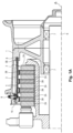
- a braked aircraft wheel comprises a rim 1 mounted to rotate about an axis of rotation ⁇ on a landing gear axle 6 by means of bearings 7.
- the rim 1 receives a tire (not shown here) and defines a cavity in which a stack of brake discs 2 extends.
- the stack 2 comprises stator discs 2A stopped in rotation alternately with rotor discs 2B which are rotated by the wheel by means of bars 3 which are fixed to the rim 1 and which cooperate with riders 4 of the rotor discs 2B protecting the notch flanks of the rotor discs 2B in which the bars 3 extend.
- the bars 3 comprise an elongated body 3A which extends substantially along a direction parallel to the axis ⁇ and which comprises a cylindrical tail-shaped end 3B which is received in an orifice 8 of the rim extending parallel to the axis X, and another end 3C which comprises a drilling 3D in a radial direction intended to receive a fixing screw 9 of the bar 3 to the rim 1.
- a shim 10 is interposed between the bar 3 and the rim 1 to both maintain the bar in a position substantially parallel to the axis of rotation ⁇ , form a mechanical interface between the bar 3 and the rim 1, and form a thermal barrier to the conduction of heat from the bar 3 to the rim 1. All this is well known and is only recalled for the purpose of illustration.
- the shim 10 comprises two support blocks 11 defining two opposite support faces, namely a support face 12 against the rim 1 and a support face 13 against the bar 3. From the support face 13 against the bar 3 and at the rear face of the shim 10 protrude two studs 14 which have the function of centering the shim 10 on the bar 3.
- the support blocks 11 are here connected to each other by a core 15 which comprises a bore 16 to allow the passage of the fixing screw 9 of the bar 3 to the rim 1.
- the support blocks 11 have oblique sides 19 so that the front face 17 of the shim 10 is smaller than its rear face 18.
- the support blocks 11 are hollowed out at a hollowing rate at least equal to 30% of their overall volume.
- all volume means the volume defined by the external dimensions of the support blocks 11, which is identical before and after hollowing.
- the hollows thus made considerably reduce the thermal conduction rate of the shim 10 and thus contribute to significantly limiting the heating of the rim 1 at the level of the support of the shim 10 on the rim 1.
- the recesses open at least onto the front face 17 and the rear face 18 of the wedge 10, so as to create in the wedges an air passage from one face to the other in the direction (1,0,0).
- the support blocks 11 of the wedge 10 have been hollowed out by producing tubular channels 20 which extend in the direction (1,0,0) from the front face to the rear face.
- eleven channels 20 have been provided in each of the support blocks 11, to obtain a hollowing rate of 33%.
- the reduction in the heat flux transmitted by conduction by the wedge is estimated at 33%.
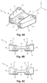
- the support blocks 11 have been hollowed out by producing channels 21 which extend in the direction (1,0,0).
- three channels with a diameter greater than that of the pipes 20 of the previous embodiment have been provided in each of the support blocks 11 to obtain a hollowing rate of 35%.
- the reduction in the heat flux transmitted by conduction by the wedge is estimated at 35%.
- the channels 20, 21 can be obtained by drilling the support blocks 11 after manufacturing the shim 10. Alternatively, they can be obtained at the same time as the rest of the shim 10 by any additive manufacturing process.
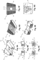
- the wedge 10 is obtained by additive manufacturing so as to provide inside the support blocks 11 a hollow lattice structure 22 whose elementary star pattern 23 is visible at the Figure 5G .
- the motif 23 is here inscribed in a cube and has branches of constant section which radiate from the center of the cube towards the eight corners of the cube, therefore in the directions (1,1,1), (1,-1,-1), (-1,-1,1) and (-1,1,-1).
- the elementary motif 23 is duplicated 9 times in the direction (1,0,0). The patterns thus duplicated are juxtaposed to each other in two layers parallel to the XY plane.
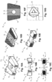
- the wedge 10 is obtained by additive manufacturing so as to provide inside the blocks 11 a hollow lattice structure 24 whose elementary star pattern 25 is visible at the Figure 6G .
- the pattern 25 is similar to that of the previous embodiment.
- the cube in which the pattern 25 is inscribed here has a side twice that of the previous embodiment, so that the patterns 25 are juxtaposed in a single layer parallel to the XY plane.
- the hollowed-out structure leads to a hollowing rate of the support blocks 11 of 51%. Compared to a solid shim, the reduction in the heat flux transmitted by conduction by the shim is estimated at 63%.
- the wedge 10 is obtained by additive manufacturing so as to provide inside the blocks 11 a hollow lattice structure 26 whose elementary tetrahedron pattern 27 is visible at the Figure 7G and comprises branches with constant section, one branch of which extends in the direction (0,0,1) and an opposite branch of which extends in the direction (1,0,0).
- This pattern is duplicated in the directions (1,0,0), 1 2 1 , 1 , 2 , ⁇ 1
- This hollowed-out structure results in a hollowing rate of the support blocks 11 of 53%.
- the reduction in the heat flow transmitted by conduction through the wedge is estimated at 67%.
- the wedge 10 is obtained by additive manufacturing so as to provide inside the blocks 11 a tetrahedron structure 28 whose elementary pattern comprises branches with constant section, one branch of which extends in the direction (0,1,0) and an opposite branch in the direction (1,0,0).
- This pattern is duplicated in the directions (1,0,0), 1 1 2 , 1 , ⁇ 1 , 2 .
- the recesses thus made also open onto the sides 29 of the blocks 11.
- This hollowed-out structure gives rise to a hollowing rate of the support blocks 11 of 37%. Compared to a solid wedge, the reduction in the heat flow transmitted by conduction by the wedge is estimated at 44%.
- the wedge 10 is obtained by additive manufacturing so as to provide inside the blocks 11 a hollow lattice structure 30 whose elementary tetrahedron pattern 31 is visible at the Figure 9G and comprises branches with constant section, one branch of which extends in the direction (0,1,0) and an opposite branch in the direction (1,0,0).
- This pattern is duplicated in the directions (1,0,0), 1 1 2 , 1 , ⁇ 1 , 2
- This hollowed-out structure results in a hollowing rate of the support blocks of 37%.
- the reduction in the heat flow transmitted by conduction through the wedge is estimated at 46%.
- the wedge 10 is obtained by additive manufacturing so as to provide inside the blocks 11 a hollow lattice structure 32 whose elementary tetrahedron pattern 33 is visible at the Figure 10G and includes branches with constant section, one branch of which extends along the direction (0,0,1) and one face extends parallel to the plane (Y,Z).
- This pattern is duplicated along the directions (0,0,1), 1 2 1 , ⁇ 2 2 , 1 , 3 .
- This hollow structure gives rise to a rate of hollowing out the support blocks by 44%. The reduction in the heat flow transmitted by conduction through the wedge is estimated at 57%.
- the shim 10 is obtained by additive manufacturing so as to provide inside the support blocks 11 a hollow lattice structure 34 whose elementary tetrahedron pattern is similar to that of the previous embodiment.
- the recesses also open onto the sides 19 of the blocks 11.
- This hollow structure leads to a hollowing rate of the support blocks 11 of 46%.
- the reduction in the heat flux transmitted by conduction by the shim is estimated at 62%.
- Removing the support blocks by at least 30% allows for a dramatic reduction in the heat flow transmitted by conduction through the shim from the bar to the rim, while preserving the shim's ability to transmit braking torque.
- Distributed recessed structures defining recesses that open onto the front and rear faces of the shim and that provide a path between the two faces will be preferred, allowing air to circulate inside the shim, particularly under the effect of forced air circulation imposed by a brake cooling fan.
- the recesses can also open onto the sides of the shim as well as onto the Figures 8A Or 11A .
Landscapes
- Engineering & Computer Science (AREA)
- General Engineering & Computer Science (AREA)
- Mechanical Engineering (AREA)
- Physics & Mathematics (AREA)
- Optics & Photonics (AREA)
- Chemical & Material Sciences (AREA)
- Materials Engineering (AREA)
- Aviation & Aerospace Engineering (AREA)
- Transportation (AREA)
- Manufacturing & Machinery (AREA)
- Braking Arrangements (AREA)
Description
- On connaît des roues d'aéronef montées sur des atterrisseurs d'aéronef et destinés à coopérer avec un frein. En général, le frein comporte des disques qui s'étendent à l'intérieur de la jante de la roue, dont des disques stators arrêtés en rotation disposés en alternance avec des disques stators entraînés en rotation par la jante de la roue par des barrettes solidaires de la jante qui s'étendent dans des encoches périphériques de disques rotors. Une pression commandée sur l'ensemble des disques génère du frottement entre les disques en regard et donc un couple de freinage qui ralentit la rotation de la roue.
- Les barrettes s'étendent à l'intérieur de la jante de la roue selon une direction sensiblement parallèle à un axe de rotation de la roue. Elles peuvent être venues de matière avec la jante de la roue ou rapportées sur cette dernière, selon diverses modalités. Certaines barrettes connues comportent à une extrémité une queue cylindrique venant s'enfoncer dans des orifices pratiqués dans le voile de la jante selon un axe parallèle à l'axe de rotation de la roue, tandis que l'autre extrémité comporte un orifice adapté à recevoir une vis s'étendant en service selon un axe radial et se vissant dans un orifice taraudé de la jante. La barrette est alors associée à une cale qui est interposée entre la barrette et la jante pour d'une part positionner la barrette selon une direction parallèle à l'axe de rotation de la roue et d'autre part contribuer à limiter les flux de chaleur entre la pile de disques et la jante de la roue.
- En effet, il importe de faire en sorte que la température de la jante ne dépasse pas des températures qui pourraient être préjudiciables au pneumatique porté par la jante dans la mesure où les barrettes sont au contact des disques rotors qui peuvent être portés à très haute température lors de certains freinages. La jante, qui est le plus souvent en alliage d'aluminium, est classiquement protégée par des écrans thermiques qui limitent l'échauffement de celle-ci par radiation. Mais la cale, qui est en contact direct de la jante, constitue un chemin de conduction susceptible de provoquer un échauffement local de la jante d'autant plus délicat qu'il intervient à proximité du talon de la jante sur lequel vient s'appuyer le pneumatique.
- On connaît du document
US 2007/246995 des cales comportant deux massifs d'appui séparés par une âme centrale percée pour laisser passer la vis de fixation de la barrette à la jante. Une telle géométrie optimise le transfert du couple de freinage, en répartissant la pression d'appui de la cale sur la jante. Cependant, elle peut donner lieu, au niveau des contacts des massifs d'appui sur la jante à des échauffements ponctuels qu'il convient de limiter. - L'invention vise à proposer une cale de barrette de roue diminuant le transfert de chaleur par la barrette des disques vers la jante.
- En vue de la réalisation de ce but, on propose une cale selon la revendication 1.
- Les évidements diminuent notablement la capacité des massifs à conduire la chaleur en provenance de la barrette vers la jante, sans altérer le transfert du couple vers la jante. Ces évidements sont facilement réalisables par des techniques de fabrication additive, selon diverses géométries.
- L'invention sera mieux comprise à la lumière de la description qui suit d'un mode particulier de réalisation de l'invention, en référence aux figures des dessins annexés, parmi lesquelles :
- La
figure 1A est une vue en coupe longitudinale d'une roue freinée montée sur un essieu d'atterrisseur d'aéronef, dont la jante est équipée de barrettes avec interposition d'une cale selon l'invention - La
figure 1B est une vue en perspective d'une des barrettes et sa cale, montrant sa disposition sur la jante de la roue ; - Les
figures 2A et 2B sont des vues en perspective de la cale et de la barrette desfigures 1A et1B , telles qu'elles sont assemblées en service ; - Les
figures 3A à 3C sont des vues en perspective, de face et de derrière qui illustrent une cale à massifs évidés selon un premier mode particulier de réalisation de l'invention ; - Les
figures 4A à 4C sont des vues en perspective, de face, de derrière, qui illustrent une cale à massifs évidés selon un deuxième mode particulier de réalisation de l'invention ; - Les
figures 5A à 5F sont des vues en perspective, de face, de derrière, puis en coupe, qui illustrent une cale à massifs évidés selon un troisième mode particulier de réalisation de l'invention ; lafigure 5G est un agrandissement de l'un des motifs internes de la cale ; - Les
figures 6A à 6F sont des vues en perspective, de face, de derrière, puis en coupe, qui illustrent une cale à massifs évidés selon un quatrième mode particulier de réalisation de l'invention ; lafigure 6G est un agrandissement de l'un des motifs internes de la cale ; - Les
figures 7A à 7F sont des vues en perspective, de face, de derrière, puis en coupe, qui illustrent une cale à massifs évidés selon un cinquième mode particulier de réalisation de l'invention ; lafigure 7G est un agrandissement de l'un des motifs internes de la cale ; - Les
figures 8A à 8F sont des vues en perspective, de face, de derrière, puis en coupe, qui illustrent une cale à massifs évidés selon un sixième mode particulier de réalisation de l'invention ; - Les
figures 9A à 9F sont des vues en perspective, de face, de derrière, puis en coupe, qui illustrent une cale à massifs évidés selon un septième mode particulier de réalisation de l'invention ; lafigure 9G est un agrandissement de l'un des motifs internes de la cale ; - Les
figures 10A à 10F sont des vues en perspective, de face, de derrière, puis en coupe, qui illustrent une cale à massifs évidés selon un huitième mode particulier de réalisation de l'invention ; lafigure 10G est un agrandissement de l'un des motifs internes de la cale ; - Les
figures 11A à 11F sont des vues en perspective, de face, de derrière, puis en coupe, qui illustrent une cale à massifs évidés selon un neuvième mode particulier de réalisation de l'invention. - Sur les figures, les axes X,Y,Z sont relatifs à la cale et quand la cale est en position sur la jante, l'axe X est parallèle à l'axe de rotation Δ de la roue, l'axe Y est parallèle à une direction orthoradiale, et l'axe Z est parallèle à une direction radiale. Les directions mentionnées ci-dessous sont données par les coordonnées (a,b,c) d'un vecteur directeur dans le repère (X,Y,Z).
- En référence aux
figures 1A à 2B , une roue freinée d'aéronef comporte une jante 1 montée pour tourner selon un axe de rotation Δ sur un essieu d'atterrisseur 6 au moyen de roulements 7. La jante 1 reçoit un pneumatique (non représenté ici) et définit une cavité dans laquelle une pile de disques de freins 2 s'étend. La pile 2 comporte des disques stators 2A arrêtés en rotation en alternance avec des disques rotors 2B qui sont entraînés en rotation par la roue au moyen de barrettes 3 qui sont fixées à la jante 1 et qui coopèrent avec des cavaliers 4 des disques rotors 2B protégeant les flancs d'encoches des disques rotors 2B dans lesquels les barrettes 3 s'étendent. Ici, les barrettes 3 comportent un corps allongé 3A qui s'étend sensiblement selon une direction parallèle à l'axe Δ et qui comporte une extrémité en forme de queue cylindrique 3B qui est reçue dans un orifice 8 de la jante s'étendant parallèlement à l'axe X, et une autre extrémité 3C qui comporte un perçage 3D selon une direction radiale destinée à recevoir une vis de fixation 9 de la barrette 3 à la jante 1. - Une cale 10 est interposée entre la barrette 3 et la jante 1 pour à la fois maintenir la barrette en position sensiblement parallèle à l'axe de rotation Δ, former une interface mécanique entre la barrette 3 et la jante 1, et former une barrière thermique à la conduction de chaleur de la barrette 3 vers la jante 1. Tout ceci est bien connu et n'est rappelé qu'à titre d'illustration.
- Ici, la cale 10 comporte deux massifs d'appui 11 définissant deux faces d'appui opposées, à savoir une face d'appui 12 contre la jante 1 et une face d'appui 13 contre la barrette 3. De la face d'appui 13 contre la barrette 3 et au niveau de la face arrière de la cale 10 saillent deux tétons 14 qui ont pour fonction de centrer la cale 10 sur la barrette 3. Les massifs d'appui 11 sont ici reliés entre eux par une âme 15 qui comporte un perçage 16 pour permettre le passage de la vis de fixation 9 de la barrette 3 à la jante 1. Dans tous les modes de réalisation illustrés ici, les massifs d'appui 11 ont des flancs obliques 19 de sorte que la face avant 17 de la cale 10 est plus petite que sa face arrière 18.
- Selon l'invention, les massifs d'appui 11 sont évidés selon un taux d'évidement au moins égal à 30% de leur volume d'encombrement. On entend ici par « volume d'encombrement » le volume défini par les dimensions extérieures des massifs d'appui 11, lequel est identique avant et après évidement. Les évidements ainsi pratiqués diminuent considérablement le taux de conduction thermique de la cale 10 et contribuent ainsi à limiter significativement l'échauffement de la jante 1 au niveau de l'appui de la cale 10 sur la jante 1. Dans tous les modes de réalisation détaillés ci-dessous, les évidements débouchent au moins sur la face avant 17 et la face arrière 18 de la cale 10, de façon à réaliser dans les cales un passage d'air d'une face à l'autre selon la direction (1,0,0).
- Selon un premier mode particulier de réalisation illustré aux
figures 3A à 3C , les massifs d'appui 11 de la cale 10 ont été évidés par la réalisation de canaux tubulaires 20 qui s'étendent selon la direction (1,0,0) de la face avant à la face arrière. Ici, onze canaux 20 ont été ménagés dans chacun des massifs d'appui 11, pour obtenir un taux d'évidement de 33%. Par rapport à une cale pleine, la diminution du flux thermique transmis par conduction par la cale est estimée à 33%. - Selon un deuxième mode particulier de réalisation illustré aux
figures 4A à 4C , les massifs d'appui 11 ont été évidés par la réalisation de canaux 21 qui s'étendent selon la direction (1,0,0). Ici, trois canaux d'un diamètre supérieur à celui des canalisations 20 du mode de réalisation précédent ont été ménagés dans chacun des massifs d'appui 11 pour obtenir un taux d'évidement de 35%. Par rapport à une cale pleine, la diminution du flux thermique transmis par conduction par la cale est estimée à 35%. - Les canaux 20,21 peuvent être obtenus par perçage des massifs d'appui 11 après fabrication de la cale 10. Alternativement, ils peuvent être obtenus en même temps que le reste de la cale 10 par tout procédé de fabrication additive.
- Selon un troisième mode particulier de réalisation illustré aux
figures 5A à 5G , la cale 10 est obtenue par fabrication additive de façon à ménager à l'intérieur des massifs d'appui 11 une structure évidée en treillis 22 dont le motif élémentaire en étoile 23 est visible à lafigure 5G . Le motif 23 s'inscrit ici dans un cube et comporte des branches de section constante qui rayonnent du centre du cube vers les huit coins du cube, donc selon les directions (1,1,1), (1,-1,-1), (-1,-1,1) et (-1,1,-1). Ici, le motif élémentaire 23 est dupliqué 9 fois dans la direction (1,0,0). Les motifs ainsi dupliqués sont juxtaposés les uns aux autres selon deux couches parallèles au plan XY. L'une des couches est visible sur lesfigures 5D et 5F où la cale a été découpée selon un plan médian parallèle au plan XY. Ici, la structure évidée conduit à un taux d'évidement des massifs d'appui 11 de 47%. Par rapport à une cale pleine, la diminution du flux thermique transmis par conduction par la cale est estimée à 60%. - Selon un quatrième mode particulier de réalisation illustré aux
figures 6A à 6G , la cale 10 est obtenue par fabrication additive de façon à ménager à l'intérieur des massifs 11 une structure évidée en treillis 24 dont le motif élémentaire en étoile 25 est visible à lafigure 6G . Le motif 25 est similaire à celui du mode de réalisation précédent. Cependant, le cube dans lequel le motif 25 s'inscrit a ici un côté double de celui du mode de réalisation précédent, de sorte que les motifs 25 sont juxtaposés selon une seule couche parallèle au plan XY. La structure évidée conduit à un taux d'évidement des massifs d'appui 11 de 51%. Par rapport à une cale pleine, la diminution du flux thermique transmis par conduction par la cale est estimée à 63%. - Selon un cinquième mode particulier de réalisation illustré aux
figures 7A à 7G , la cale 10 est obtenue par fabrication additive de façon à ménager à l'intérieur de massifs 11 une structure évidée en treillis 26 dont le motif élémentaire en tétraèdre 27 est visible à lafigure 7G et comprend des branches à section constante dont une branche s'étend selon la direction (0,0,1) et une branche opposée s'étend selon la direction (1,0,0). Ce motif est dupliqué selon les directions (1,0,0),
- Selon un sixième mode particulier de réalisation illustré aux
figures 8A à 8F , la cale 10 est obtenue par fabrication additive de façon à ménager à l'intérieur de massifs 11 une structure en tétraèdre 28 dont le motif élémentaire comprend des branches à section constante dont une branche s'étend selon la direction (0,1,0) et une branche opposée selon la direction (1,0,0). Ce motif est dupliqué selon les directions (1,0,0),
- Selon un septième mode particulier de réalisation illustré aux
figures 9A à 9G , la cale 10 est obtenue par fabrication additive de façon à ménager à l'intérieur de massifs 11 une structure évidée en treillis 30 dont le motif élémentaire en tétraèdre 31 est visible à lafigure 9G et comprend des branches à section constante dont une branche s'étend selon la direction (0,1,0) et une branche opposée selon la direction (1,0,0). Ce motif est dupliqué selon les directions (1,0,0),

- Selon un huitième mode particulier de réalisation illustré aux
figures 10A à 10G , la cale 10 est obtenue par fabrication additive de façon à ménager à l'intérieur de massifs 11 une structure évidée en treillis 32 dont le motif élémentaire en tétraèdre 33 est visible à lafigure 10G et comprend des branches à section constante dont une branche s'étend selon la direction (0,0,1) et une face s'étend parallèlement au plan (Y,Z). Ce motif est dupliqué selon les directions (0,0,1),

figures 11A à 11F , la cale 10 est obtenue par fabrication additive de façon à ménager à l'intérieur de massifs d'appui 11 une structure évidée en treillis 34 dont le motif élémentaire en tétraèdre est similaire à celui du mode de réalisation précédent. Dans ce mode de réalisation, les évidements débouchent en outre sur les flancs 19 des massifs 11. Cette structure évidée conduit à un taux d'évidement des massifs d'appui 11 de 46%. Par rapport à une cale pleine, la diminution du flux thermique transmis par conduction par la cale est estimée à 62%. - L'évidement des massifs d'appui d'au moins 30% permet une diminution spectaculaire du flux de chaleur transmis par conduction par la cale de la barrette vers la jante, tout en préservant la capacité de la cale à transmettre le couple de freinage. On privilégiera des structures évidées réparties définissant des évidements qui débouchent sur la face avant et la face arrière de la cale et qui ménagent un chemin entre les deux faces, permettant à l'air de circuler à l'intérieur de la cale, notamment sous l'effet d'une circulation forcée d'air imposée par un ventilateur de refroidissement des freins. Les évidements peuvent également déboucher sur les flancs de la cale comme sur les
figures 8A ou11A . - L'invention n'est pas limitée à ce qui vient d'être décrit, mais englobe au contraire toute variante entrant dans le cadre défini par les revendications. En particulier, bien que les évidements soient ici obtenus par des canaux tubulaires ou par répétition de motifs à branches évidés, tout autre géométrie pourra être envisagée du moment qu'elle donne lieu à un taux d'évidement des massifs d'appui au moins égal à 30%.
Claims (7)
- Cale (10) pour roue freinée d'aéronef destinée à être interposée entre une jante (1) et une barrette (3) rapportée sur la jante pour entraîner en rotation des disques rotors de frein, la cale comportant deux massifs d'appui (11) reliés par une âme (15) qui est percée pour laisser passer une vis de fixation de la barrette à la jante, la cale comportant une face avant (17) et une face arrière (18) en référence à une direction longitudinale de la barrette en appui contre la cale, caractérisée en ce que les massifs d'appui (11) de la cale comportent des évidements définissant un taux d'évidement d'au moins 30% d'un volume d'encombrement des massifs d'appui, le volume d'encombrement des massifs d'appui étant identique avec et sans les évidements, et les évidements débouchant sur la face avant et la face arrière de la cale pour ménager dans la cale un passage d'air entre ladite face avant et ladite face arrière.
- Cale (10) selon la revendication 1, dans lequel les évidements débouchent sur des flancs (19) de la cale.
- Cale (10) selon la revendication 1, dans lequel les évidements sont obtenus par réalisation de canaux tubulaires (20;21) dans les massifs d'appui s'étendant de la face avant (17) à la face arrière (18) de la cale.
- Cale (10) selon la revendication 1, dans laquelle les évidements sont obtenus au moyen d'une structure évidée définie par répétition d'un motif à branches (23;25;27;30;31;33) et qui s'étend de la face avant (17) à la face arrière (18) de la cale.
- Cale (10) selon la revendication 4, dans laquelle le motif est un motif en étoile (23;25) inscrit dans un cube dont les branches rayonnent du centre du cube vers les huit coins du cube.
- Cale (10) selon la revendication 4, dans laquelle le motif élémentaire est un motif (27;30;31;33) en tétraèdre.
- Jante (1) de roue freinée d'aéronef, la jante est équipée de barrettes (3) fixées à la jante avec interposition de cales (10) selon l'une des revendications précédentes, chaque barrette étant maintenue en appui contre l'une des cales par la vis de fixation de la barrette à la jante.
Applications Claiming Priority (1)
| Application Number | Priority Date | Filing Date | Title |
|---|---|---|---|
| FR1760000A FR3072648B1 (fr) | 2017-10-23 | 2017-10-23 | Cale de barrette de roue freinee d'aeronef |
Publications (2)
| Publication Number | Publication Date |
|---|---|
| EP3473541A1 EP3473541A1 (fr) | 2019-04-24 |
| EP3473541B1 true EP3473541B1 (fr) | 2025-04-02 |
Family
ID=60627872
Family Applications (1)
| Application Number | Title | Priority Date | Filing Date |
|---|---|---|---|
| EP18201074.4A Active EP3473541B1 (fr) | 2017-10-23 | 2018-10-17 | Cale de barrette de roue freinée d'aéronef |
Country Status (4)
| Country | Link |
|---|---|
| US (1) | US11408473B2 (fr) |
| EP (1) | EP3473541B1 (fr) |
| CN (1) | CN109693784A (fr) |
| FR (1) | FR3072648B1 (fr) |
Families Citing this family (8)
| Publication number | Priority date | Publication date | Assignee | Title |
|---|---|---|---|---|
| FR3097197B1 (fr) | 2019-06-14 | 2021-07-02 | Safran Landing Systems | Barrette pour roue freinee d’aeronef |
| EP3753793B1 (fr) | 2019-06-21 | 2023-02-22 | Goodrich Corporation | Système de freinage pour roue d'aéronef |
| US11644071B2 (en) * | 2019-07-08 | 2023-05-09 | Honeywell International Inc. | Rotor drive key assembly |
| US11320010B2 (en) | 2020-04-02 | 2022-05-03 | Honeywell International Inc. | Braking system |
| US11473630B2 (en) * | 2020-04-08 | 2022-10-18 | Honeywell International Inc. | Rotor drive key assembly |
| FR3117448B1 (fr) * | 2020-12-10 | 2024-05-31 | Safran Landing Systems | Roue freinée d’aéronef |
| FR3133165B1 (fr) * | 2022-03-02 | 2024-05-31 | Safran Landing Systems | Dispositif de roulage à freinage mixte friction/magnétique, et aéronef ainsi équipé |
| US12545398B2 (en) | 2023-02-09 | 2026-02-10 | Goodrich Corporation | Use of profiled reaction face in hybrid torque bar applications |
Family Cites Families (15)
| Publication number | Priority date | Publication date | Assignee | Title |
|---|---|---|---|---|
| US4526616A (en) * | 1982-07-27 | 1985-07-02 | Dunlop Limited | Load-bearing thermal insulator |
| DE3740912A1 (de) * | 1987-12-03 | 1989-06-15 | Buderus Kundenguss | Verwendung einer gusseisensorte fuer bremsenkoerper |
| US5024297A (en) * | 1989-05-16 | 1991-06-18 | The B. F. Goodrich Company | Torque transmitting beam for wheel having brake torque drives |
| JP3521266B2 (ja) * | 1994-09-08 | 2004-04-19 | 株式会社豊田中央研究所 | ブレーキディスクロータ |
| US5851056A (en) * | 1996-06-03 | 1998-12-22 | The B. F. Goodrich Company | Aircraft brake heat shield having easily removed heat shield sections |
| US6003954A (en) * | 1997-08-25 | 1999-12-21 | Aircraft Braking Systems Corporation | Aircraft wheel and beam key attachment |
| US7051845B2 (en) * | 2001-10-10 | 2006-05-30 | Goodrich Corporation | Heat shield assembly for aircraft wheel and brake assembly |
| US7488044B2 (en) * | 2006-04-25 | 2009-02-10 | Honeywell International Inc. | Beam key and wheel assembly including same |
| GB0913580D0 (en) * | 2009-08-05 | 2009-09-16 | Rolls Royce Plc | Combustor tile |
| GB201222311D0 (en) * | 2012-12-12 | 2013-01-23 | Rolls Royce Plc | A combusiton chamber |
| US9850968B2 (en) * | 2014-04-29 | 2017-12-26 | Goodrich Corporation | Torque bar and methods for making |
| US9851105B2 (en) * | 2014-07-03 | 2017-12-26 | United Technologies Corporation | Self-cooled orifice structure |
| SE1550140A1 (sv) * | 2015-02-09 | 2016-08-10 | Titanx Engine Cooling Holding Ab | Port flange for a heat exchanger, heat exchanger comprising a port flange and method of making a port flange |
| CN205553074U (zh) * | 2016-01-13 | 2016-09-07 | 贝普医疗科技有限公司 | 一种热流道模具的隔热密封装置 |
| US10077818B2 (en) * | 2016-06-17 | 2018-09-18 | Goodrich Corporation | Scalloped aircraft wheel rotor drive bar attachment boss for reduced thermal conduction |
-
2017
- 2017-10-23 FR FR1760000A patent/FR3072648B1/fr active Active
-
2018
- 2018-10-17 EP EP18201074.4A patent/EP3473541B1/fr active Active
- 2018-10-19 US US16/165,105 patent/US11408473B2/en active Active
- 2018-10-23 CN CN201811238690.9A patent/CN109693784A/zh active Pending
Also Published As
| Publication number | Publication date |
|---|---|
| US20190120304A1 (en) | 2019-04-25 |
| EP3473541A1 (fr) | 2019-04-24 |
| US11408473B2 (en) | 2022-08-09 |
| FR3072648B1 (fr) | 2021-11-12 |
| FR3072648A1 (fr) | 2019-04-26 |
| CN109693784A (zh) | 2019-04-30 |
Similar Documents
| Publication | Publication Date | Title |
|---|---|---|
| EP3473541A1 (fr) | Cale de barrette de roue freinée d'aéronef | |
| EP0235036B1 (fr) | Perfectionnements aux rotors induits des ralentisseurs électromagnétiques | |
| EP3647188B1 (fr) | Ecran thermique pour roue freinee d'aeronef | |
| FR2568645A1 (fr) | Disque de frein comportant deux elements entre lesquels est interpose un disque separateur | |
| EP2876326B1 (fr) | Procédé de rénovation et d'utilisation de disques de frein de type stator arrière à plots, disque assemblé et pile de disques correspondante | |
| EP4110691A1 (fr) | Rotor de soufflante à aubes à calage variable et turbomachine équipée d'un tel rotor | |
| EP0209460B1 (fr) | Perfectionnements aux rotors induits des ralentisseurs électromagnétiques | |
| WO2010020334A2 (fr) | Rotor interieur pour machine electrique tournante et son procede d'assemblage | |
| EP4263346B1 (fr) | Dispositif de freinage d'une roue d'aeronef | |
| EP0327476A1 (fr) | Frein à disques pour arbre tournant | |
| EP4146537B1 (fr) | Ecran thermique pour dispositif de freinage d'une roue d'aeronef | |
| EP4185528B1 (fr) | Ensemble d'écran thermique | |
| CA2554092C (fr) | Verrouillage des aubes dans un rotor de soufflante | |
| FR2935204A1 (fr) | Rotor interieur a arbre rainure pour machine electrique tournante | |
| FR2745349A1 (fr) | Disque de frein modulaire | |
| FR3054524A1 (fr) | Ecran thermique de roue freinee d'aeronef a obstacles | |
| EP3983293B1 (fr) | Barrette pour roue freinee d'aeronef | |
| FR3003201A1 (fr) | Assemblage d’un moyeu de roue motrice et d’un bol de joint de transmission | |
| FR2678992A1 (fr) | Systeme de freinage a disques accoles, notamment pour roues d'avions. | |
| EP2000693B1 (fr) | Ensemble de roue et frein pour aéronef | |
| EP1367285A1 (fr) | Frein à disque, notamment our usage industriel | |
| FR3166674A1 (fr) | Dispositif de freinage à tenons de transmission de couple rapportés, roue, atterrisseur et aéronef le comportant. | |
| FR2766732A1 (fr) | Outil d'extraction d'un roulement, notamment pour roue de patin a roues en ligne | |
| FR3159643A1 (fr) | Disque de frein pour véhicule automobile | |
| WO2026104377A1 (fr) | Barrette et cale pour roue freinée d'aéronef |
Legal Events
| Date | Code | Title | Description |
|---|---|---|---|
| PUAI | Public reference made under article 153(3) epc to a published international application that has entered the european phase |
Free format text: ORIGINAL CODE: 0009012 |
|
| STAA | Information on the status of an ep patent application or granted ep patent |
Free format text: STATUS: THE APPLICATION HAS BEEN PUBLISHED |
|
| AK | Designated contracting states |
Kind code of ref document: A1 Designated state(s): AL AT BE BG CH CY CZ DE DK EE ES FI FR GB GR HR HU IE IS IT LI LT LU LV MC MK MT NL NO PL PT RO RS SE SI SK SM TR |
|
| AX | Request for extension of the european patent |
Extension state: BA ME |
|
| STAA | Information on the status of an ep patent application or granted ep patent |
Free format text: STATUS: REQUEST FOR EXAMINATION WAS MADE |
|
| 17P | Request for examination filed |
Effective date: 20191009 |
|
| RBV | Designated contracting states (corrected) |
Designated state(s): AL AT BE BG CH CY CZ DE DK EE ES FI FR GB GR HR HU IE IS IT LI LT LU LV MC MK MT NL NO PL PT RO RS SE SI SK SM TR |
|
| STAA | Information on the status of an ep patent application or granted ep patent |
Free format text: STATUS: EXAMINATION IS IN PROGRESS |
|
| 17Q | First examination report despatched |
Effective date: 20201112 |
|
| GRAP | Despatch of communication of intention to grant a patent |
Free format text: ORIGINAL CODE: EPIDOSNIGR1 |
|
| STAA | Information on the status of an ep patent application or granted ep patent |
Free format text: STATUS: GRANT OF PATENT IS INTENDED |
|
| RIC1 | Information provided on ipc code assigned before grant |
Ipc: B29C 64/153 20170101ALI20241030BHEP Ipc: F16B 43/02 20060101ALI20241030BHEP Ipc: F16B 43/00 20060101ALI20241030BHEP Ipc: F16D 65/095 20060101ALI20241030BHEP Ipc: F16D 65/092 20060101ALI20241030BHEP Ipc: F16D 65/02 20060101ALI20241030BHEP Ipc: F16D 55/36 20060101ALI20241030BHEP Ipc: B60T 1/06 20060101ALI20241030BHEP Ipc: B64C 25/42 20060101AFI20241030BHEP |
|
| INTG | Intention to grant announced |
Effective date: 20241119 |
|
| GRAS | Grant fee paid |
Free format text: ORIGINAL CODE: EPIDOSNIGR3 |
|
| GRAA | (expected) grant |
Free format text: ORIGINAL CODE: 0009210 |
|
| STAA | Information on the status of an ep patent application or granted ep patent |
Free format text: STATUS: THE PATENT HAS BEEN GRANTED |
|
| AK | Designated contracting states |
Kind code of ref document: B1 Designated state(s): AL AT BE BG CH CY CZ DE DK EE ES FI FR GB GR HR HU IE IS IT LI LT LU LV MC MK MT NL NO PL PT RO RS SE SI SK SM TR |
|
| REG | Reference to a national code |
Ref country code: GB Ref legal event code: FG4D Free format text: NOT ENGLISH |
|
| REG | Reference to a national code |
Ref country code: CH Ref legal event code: EP |
|
| REG | Reference to a national code |
Ref country code: DE Ref legal event code: R096 Ref document number: 602018080664 Country of ref document: DE |
|
| REG | Reference to a national code |
Ref country code: IE Ref legal event code: FG4D Free format text: LANGUAGE OF EP DOCUMENT: FRENCH |
|
| REG | Reference to a national code |
Ref country code: NL Ref legal event code: MP Effective date: 20250402 |
|
| PG25 | Lapsed in a contracting state [announced via postgrant information from national office to epo] |
Ref country code: NL Free format text: LAPSE BECAUSE OF FAILURE TO SUBMIT A TRANSLATION OF THE DESCRIPTION OR TO PAY THE FEE WITHIN THE PRESCRIBED TIME-LIMIT Effective date: 20250402 |
|
| REG | Reference to a national code |
Ref country code: AT Ref legal event code: MK05 Ref document number: 1781088 Country of ref document: AT Kind code of ref document: T Effective date: 20250402 |
|
| PG25 | Lapsed in a contracting state [announced via postgrant information from national office to epo] |
Ref country code: PT Free format text: LAPSE BECAUSE OF FAILURE TO SUBMIT A TRANSLATION OF THE DESCRIPTION OR TO PAY THE FEE WITHIN THE PRESCRIBED TIME-LIMIT Effective date: 20250804 Ref country code: ES Free format text: LAPSE BECAUSE OF FAILURE TO SUBMIT A TRANSLATION OF THE DESCRIPTION OR TO PAY THE FEE WITHIN THE PRESCRIBED TIME-LIMIT Effective date: 20250402 Ref country code: FI Free format text: LAPSE BECAUSE OF FAILURE TO SUBMIT A TRANSLATION OF THE DESCRIPTION OR TO PAY THE FEE WITHIN THE PRESCRIBED TIME-LIMIT Effective date: 20250402 |
|
| REG | Reference to a national code |
Ref country code: LT Ref legal event code: MG9D |
|
| PG25 | Lapsed in a contracting state [announced via postgrant information from national office to epo] |
Ref country code: GR Free format text: LAPSE BECAUSE OF FAILURE TO SUBMIT A TRANSLATION OF THE DESCRIPTION OR TO PAY THE FEE WITHIN THE PRESCRIBED TIME-LIMIT Effective date: 20250703 Ref country code: NO Free format text: LAPSE BECAUSE OF FAILURE TO SUBMIT A TRANSLATION OF THE DESCRIPTION OR TO PAY THE FEE WITHIN THE PRESCRIBED TIME-LIMIT Effective date: 20250702 |
|
| PG25 | Lapsed in a contracting state [announced via postgrant information from national office to epo] |
Ref country code: PL Free format text: LAPSE BECAUSE OF FAILURE TO SUBMIT A TRANSLATION OF THE DESCRIPTION OR TO PAY THE FEE WITHIN THE PRESCRIBED TIME-LIMIT Effective date: 20250402 |
|
| PG25 | Lapsed in a contracting state [announced via postgrant information from national office to epo] |
Ref country code: BG Free format text: LAPSE BECAUSE OF FAILURE TO SUBMIT A TRANSLATION OF THE DESCRIPTION OR TO PAY THE FEE WITHIN THE PRESCRIBED TIME-LIMIT Effective date: 20250402 |
|
| PG25 | Lapsed in a contracting state [announced via postgrant information from national office to epo] |
Ref country code: HR Free format text: LAPSE BECAUSE OF FAILURE TO SUBMIT A TRANSLATION OF THE DESCRIPTION OR TO PAY THE FEE WITHIN THE PRESCRIBED TIME-LIMIT Effective date: 20250402 |
|
| PG25 | Lapsed in a contracting state [announced via postgrant information from national office to epo] |
Ref country code: AT Free format text: LAPSE BECAUSE OF FAILURE TO SUBMIT A TRANSLATION OF THE DESCRIPTION OR TO PAY THE FEE WITHIN THE PRESCRIBED TIME-LIMIT Effective date: 20250402 |
|
| PG25 | Lapsed in a contracting state [announced via postgrant information from national office to epo] |
Ref country code: RS Free format text: LAPSE BECAUSE OF FAILURE TO SUBMIT A TRANSLATION OF THE DESCRIPTION OR TO PAY THE FEE WITHIN THE PRESCRIBED TIME-LIMIT Effective date: 20250702 |
|
| PG25 | Lapsed in a contracting state [announced via postgrant information from national office to epo] |
Ref country code: IS Free format text: LAPSE BECAUSE OF FAILURE TO SUBMIT A TRANSLATION OF THE DESCRIPTION OR TO PAY THE FEE WITHIN THE PRESCRIBED TIME-LIMIT Effective date: 20250802 |
|
| PG25 | Lapsed in a contracting state [announced via postgrant information from national office to epo] |
Ref country code: LV Free format text: LAPSE BECAUSE OF FAILURE TO SUBMIT A TRANSLATION OF THE DESCRIPTION OR TO PAY THE FEE WITHIN THE PRESCRIBED TIME-LIMIT Effective date: 20250402 |
|
| REG | Reference to a national code |
Ref country code: DE Ref legal event code: R097 Ref document number: 602018080664 Country of ref document: DE |
|
| PGFP | Annual fee paid to national office [announced via postgrant information from national office to epo] |
Ref country code: DE Payment date: 20251020 Year of fee payment: 8 |
|
| PGFP | Annual fee paid to national office [announced via postgrant information from national office to epo] |
Ref country code: GB Payment date: 20251029 Year of fee payment: 8 |
|
| PG25 | Lapsed in a contracting state [announced via postgrant information from national office to epo] |
Ref country code: DK Free format text: LAPSE BECAUSE OF FAILURE TO SUBMIT A TRANSLATION OF THE DESCRIPTION OR TO PAY THE FEE WITHIN THE PRESCRIBED TIME-LIMIT Effective date: 20250402 Ref country code: SM Free format text: LAPSE BECAUSE OF FAILURE TO SUBMIT A TRANSLATION OF THE DESCRIPTION OR TO PAY THE FEE WITHIN THE PRESCRIBED TIME-LIMIT Effective date: 20250402 |
|
| PGFP | Annual fee paid to national office [announced via postgrant information from national office to epo] |
Ref country code: FR Payment date: 20251024 Year of fee payment: 8 |
|
| PG25 | Lapsed in a contracting state [announced via postgrant information from national office to epo] |
Ref country code: CZ Free format text: LAPSE BECAUSE OF FAILURE TO SUBMIT A TRANSLATION OF THE DESCRIPTION OR TO PAY THE FEE WITHIN THE PRESCRIBED TIME-LIMIT Effective date: 20250402 |
|
| PG25 | Lapsed in a contracting state [announced via postgrant information from national office to epo] |
Ref country code: EE Free format text: LAPSE BECAUSE OF FAILURE TO SUBMIT A TRANSLATION OF THE DESCRIPTION OR TO PAY THE FEE WITHIN THE PRESCRIBED TIME-LIMIT Effective date: 20250402 |
|
| PG25 | Lapsed in a contracting state [announced via postgrant information from national office to epo] |
Ref country code: SK Free format text: LAPSE BECAUSE OF FAILURE TO SUBMIT A TRANSLATION OF THE DESCRIPTION OR TO PAY THE FEE WITHIN THE PRESCRIBED TIME-LIMIT Effective date: 20250402 Ref country code: RO Free format text: LAPSE BECAUSE OF FAILURE TO SUBMIT A TRANSLATION OF THE DESCRIPTION OR TO PAY THE FEE WITHIN THE PRESCRIBED TIME-LIMIT Effective date: 20250402 |
|
| PG25 | Lapsed in a contracting state [announced via postgrant information from national office to epo] |
Ref country code: IT Free format text: LAPSE BECAUSE OF FAILURE TO SUBMIT A TRANSLATION OF THE DESCRIPTION OR TO PAY THE FEE WITHIN THE PRESCRIBED TIME-LIMIT Effective date: 20250402 |
|
| PLBE | No opposition filed within time limit |
Free format text: ORIGINAL CODE: 0009261 |
|
| STAA | Information on the status of an ep patent application or granted ep patent |
Free format text: STATUS: NO OPPOSITION FILED WITHIN TIME LIMIT |
|
| REG | Reference to a national code |
Ref country code: CH Ref legal event code: L10 Free format text: ST27 STATUS EVENT CODE: U-0-0-L10-L00 (AS PROVIDED BY THE NATIONAL OFFICE) Effective date: 20260211 |
|
| 26N | No opposition filed |
Effective date: 20260105 |