EP3473483A1 - Inverter for an electric machine, electric machine for a vehicle, vehicle and method for operating an inverter - Google Patents
Inverter for an electric machine, electric machine for a vehicle, vehicle and method for operating an inverter Download PDFInfo
- Publication number
- EP3473483A1 EP3473483A1 EP17196910.8A EP17196910A EP3473483A1 EP 3473483 A1 EP3473483 A1 EP 3473483A1 EP 17196910 A EP17196910 A EP 17196910A EP 3473483 A1 EP3473483 A1 EP 3473483A1
- Authority
- EP
- European Patent Office
- Prior art keywords
- inverter
- link
- line
- electric machine
- input terminal
- Prior art date
- Legal status (The legal status is an assumption and is not a legal conclusion. Google has not performed a legal analysis and makes no representation as to the accuracy of the status listed.)
- Granted
Links
Images

Classifications
-
- B—PERFORMING OPERATIONS; TRANSPORTING
- B60—VEHICLES IN GENERAL
- B60L—PROPULSION OF ELECTRICALLY-PROPELLED VEHICLES; SUPPLYING ELECTRIC POWER FOR AUXILIARY EQUIPMENT OF ELECTRICALLY-PROPELLED VEHICLES; ELECTRODYNAMIC BRAKE SYSTEMS FOR VEHICLES IN GENERAL; MAGNETIC SUSPENSION OR LEVITATION FOR VEHICLES; MONITORING OPERATING VARIABLES OF ELECTRICALLY-PROPELLED VEHICLES; ELECTRIC SAFETY DEVICES FOR ELECTRICALLY-PROPELLED VEHICLES
- B60L3/00—Electric devices on electrically-propelled vehicles for safety purposes; Monitoring operating variables, e.g. speed, deceleration or energy consumption
- B60L3/0023—Detecting, eliminating, remedying or compensating for drive train abnormalities, e.g. failures within the drive train
- B60L3/003—Detecting, eliminating, remedying or compensating for drive train abnormalities, e.g. failures within the drive train relating to inverters
-
- B—PERFORMING OPERATIONS; TRANSPORTING
- B60—VEHICLES IN GENERAL
- B60L—PROPULSION OF ELECTRICALLY-PROPELLED VEHICLES; SUPPLYING ELECTRIC POWER FOR AUXILIARY EQUIPMENT OF ELECTRICALLY-PROPELLED VEHICLES; ELECTRODYNAMIC BRAKE SYSTEMS FOR VEHICLES IN GENERAL; MAGNETIC SUSPENSION OR LEVITATION FOR VEHICLES; MONITORING OPERATING VARIABLES OF ELECTRICALLY-PROPELLED VEHICLES; ELECTRIC SAFETY DEVICES FOR ELECTRICALLY-PROPELLED VEHICLES
- B60L15/00—Methods, circuits, or devices for controlling the traction-motor speed of electrically-propelled vehicles
- B60L15/007—Physical arrangements or structures of drive train converters specially adapted for the propulsion motors of electric vehicles
-
- B—PERFORMING OPERATIONS; TRANSPORTING
- B60—VEHICLES IN GENERAL
- B60L—PROPULSION OF ELECTRICALLY-PROPELLED VEHICLES; SUPPLYING ELECTRIC POWER FOR AUXILIARY EQUIPMENT OF ELECTRICALLY-PROPELLED VEHICLES; ELECTRODYNAMIC BRAKE SYSTEMS FOR VEHICLES IN GENERAL; MAGNETIC SUSPENSION OR LEVITATION FOR VEHICLES; MONITORING OPERATING VARIABLES OF ELECTRICALLY-PROPELLED VEHICLES; ELECTRIC SAFETY DEVICES FOR ELECTRICALLY-PROPELLED VEHICLES
- B60L3/00—Electric devices on electrically-propelled vehicles for safety purposes; Monitoring operating variables, e.g. speed, deceleration or energy consumption
- B60L3/0023—Detecting, eliminating, remedying or compensating for drive train abnormalities, e.g. failures within the drive train
- B60L3/0061—Detecting, eliminating, remedying or compensating for drive train abnormalities, e.g. failures within the drive train relating to electrical machines
-
- B—PERFORMING OPERATIONS; TRANSPORTING
- B60—VEHICLES IN GENERAL
- B60L—PROPULSION OF ELECTRICALLY-PROPELLED VEHICLES; SUPPLYING ELECTRIC POWER FOR AUXILIARY EQUIPMENT OF ELECTRICALLY-PROPELLED VEHICLES; ELECTRODYNAMIC BRAKE SYSTEMS FOR VEHICLES IN GENERAL; MAGNETIC SUSPENSION OR LEVITATION FOR VEHICLES; MONITORING OPERATING VARIABLES OF ELECTRICALLY-PROPELLED VEHICLES; ELECTRIC SAFETY DEVICES FOR ELECTRICALLY-PROPELLED VEHICLES
- B60L3/00—Electric devices on electrically-propelled vehicles for safety purposes; Monitoring operating variables, e.g. speed, deceleration or energy consumption
- B60L3/0092—Electric devices on electrically-propelled vehicles for safety purposes; Monitoring operating variables, e.g. speed, deceleration or energy consumption with use of redundant elements for safety purposes
-
- B—PERFORMING OPERATIONS; TRANSPORTING
- B60—VEHICLES IN GENERAL
- B60L—PROPULSION OF ELECTRICALLY-PROPELLED VEHICLES; SUPPLYING ELECTRIC POWER FOR AUXILIARY EQUIPMENT OF ELECTRICALLY-PROPELLED VEHICLES; ELECTRODYNAMIC BRAKE SYSTEMS FOR VEHICLES IN GENERAL; MAGNETIC SUSPENSION OR LEVITATION FOR VEHICLES; MONITORING OPERATING VARIABLES OF ELECTRICALLY-PROPELLED VEHICLES; ELECTRIC SAFETY DEVICES FOR ELECTRICALLY-PROPELLED VEHICLES
- B60L3/00—Electric devices on electrically-propelled vehicles for safety purposes; Monitoring operating variables, e.g. speed, deceleration or energy consumption
- B60L3/04—Cutting off the power supply under fault conditions
-
- H—ELECTRICITY
- H02—GENERATION; CONVERSION OR DISTRIBUTION OF ELECTRIC POWER
- H02H—EMERGENCY PROTECTIVE CIRCUIT ARRANGEMENTS
- H02H7/00—Emergency protective circuit arrangements specially adapted for specific types of electric machines or apparatus or for sectionalised protection of cable or line systems, and effecting automatic switching in the event of an undesired change from normal working conditions
- H02H7/10—Emergency protective circuit arrangements specially adapted for specific types of electric machines or apparatus or for sectionalised protection of cable or line systems, and effecting automatic switching in the event of an undesired change from normal working conditions for converters; for rectifiers
- H02H7/12—Emergency protective circuit arrangements specially adapted for specific types of electric machines or apparatus or for sectionalised protection of cable or line systems, and effecting automatic switching in the event of an undesired change from normal working conditions for converters; for rectifiers for static converters or rectifiers
- H02H7/122—Emergency protective circuit arrangements specially adapted for specific types of electric machines or apparatus or for sectionalised protection of cable or line systems, and effecting automatic switching in the event of an undesired change from normal working conditions for converters; for rectifiers for static converters or rectifiers for inverters, i.e. DC/AC converters
-
- H—ELECTRICITY
- H02—GENERATION; CONVERSION OR DISTRIBUTION OF ELECTRIC POWER
- H02P—CONTROL OR REGULATION OF ELECTRIC MOTORS, ELECTRIC GENERATORS OR DYNAMO-ELECTRIC CONVERTERS; CONTROLLING TRANSFORMERS, REACTORS OR CHOKE COILS
- H02P3/00—Arrangements for stopping or slowing electric motors, generators, or dynamo-electric converters
- H02P3/06—Arrangements for stopping or slowing electric motors, generators, or dynamo-electric converters for stopping or slowing an individual dynamo-electric motor or dynamo-electric converter
- H02P3/18—Arrangements for stopping or slowing electric motors, generators, or dynamo-electric converters for stopping or slowing an individual dynamo-electric motor or dynamo-electric converter for stopping or slowing an AC motor
-
- H—ELECTRICITY
- H02—GENERATION; CONVERSION OR DISTRIBUTION OF ELECTRIC POWER
- H02P—CONTROL OR REGULATION OF ELECTRIC MOTORS, ELECTRIC GENERATORS OR DYNAMO-ELECTRIC CONVERTERS; CONTROLLING TRANSFORMERS, REACTORS OR CHOKE COILS
- H02P3/00—Arrangements for stopping or slowing electric motors, generators, or dynamo-electric converters
- H02P3/06—Arrangements for stopping or slowing electric motors, generators, or dynamo-electric converters for stopping or slowing an individual dynamo-electric motor or dynamo-electric converter
- H02P3/18—Arrangements for stopping or slowing electric motors, generators, or dynamo-electric converters for stopping or slowing an individual dynamo-electric motor or dynamo-electric converter for stopping or slowing an AC motor
- H02P3/22—Arrangements for stopping or slowing electric motors, generators, or dynamo-electric converters for stopping or slowing an individual dynamo-electric motor or dynamo-electric converter for stopping or slowing an AC motor by short-circuit or resistive braking
-
- H—ELECTRICITY
- H02—GENERATION; CONVERSION OR DISTRIBUTION OF ELECTRIC POWER
- H02H—EMERGENCY PROTECTIVE CIRCUIT ARRANGEMENTS
- H02H3/00—Emergency protective circuit arrangements for automatic disconnection directly responsive to an undesired change from normal electric working condition with or without subsequent reconnection ; integrated protection
- H02H3/02—Details
- H02H3/05—Details with means for increasing reliability, e.g. redundancy arrangements
-
- Y—GENERAL TAGGING OF NEW TECHNOLOGICAL DEVELOPMENTS; GENERAL TAGGING OF CROSS-SECTIONAL TECHNOLOGIES SPANNING OVER SEVERAL SECTIONS OF THE IPC; TECHNICAL SUBJECTS COVERED BY FORMER USPC CROSS-REFERENCE ART COLLECTIONS [XRACs] AND DIGESTS
- Y02—TECHNOLOGIES OR APPLICATIONS FOR MITIGATION OR ADAPTATION AGAINST CLIMATE CHANGE
- Y02T—CLIMATE CHANGE MITIGATION TECHNOLOGIES RELATED TO TRANSPORTATION
- Y02T10/00—Road transport of goods or passengers
- Y02T10/60—Other road transportation technologies with climate change mitigation effect
- Y02T10/64—Electric machine technologies in electromobility
Definitions
- the invention relates to an inverter for an electric machine, comprising an input terminal connectable to a DC voltage, a DC link connected to the input terminal, an output terminal connectable to stator windings of the electric machine and a controller configured to provide in a pulsing mode pulsing signals causing the inverter to convert the DC voltage into a multiphase AC output voltage at the output terminal and to transfer the inverter from the pulsing mode into an active short circuit mode.
- the invention relates to an electric machine for a vehicle, a vehicle and method for operating an inverter.
- Inverters are widely known for converting a DC voltage supplied to a DC link via an input terminal into a multiphase AC output voltage.
- BEV battery electric vehicles
- hybrid electric vehicles the inverter has to be transferred into a safe mode if a failure is detected or an external signal is received.
- SPO safe pulse off mode
- the electromagnetic force of the stator windings may be higher than the DC voltage, a current may flow from an output terminal via the DC link to the input terminal causing a perceptible braking torque.
- the braking torque may exceed a tolerable level with respect to automotive functional safety.
- the switching elements are in a switching configuration, in which the switching elements connected to a high potential of the DC link are in a conducting state and switching elements connected to a low potential of the DC link are in the blocking state or vice versa.
- an active short circuit mode requires to hold the switching configuration with a certain integrity. If it is not possible to hold the switching configuration, e.g. due to a damage of a switching element, both switching elements of one or more half bridges may be in the blocking switching state. As such a switching configuration allows a current flow from the output terminal to the input terminal, the braking torques may occur although an active short circuit mode should be adopted.
- this object is solved by an inverter as initially described, wherein the controller is configured to control at least one interrupt device being arranged in a line of the DC link to interrupt a current flow along the line transmitting power from the output terminal to the input terminal if the inverter is transferred from the pulsing mode into the active short circuit mode.
- the invention is based upon the consideration to avoid the power transmission from the output terminal to the DC link by the interrupt device.
- the current flow results from an electromagnetic force (e.m.f.), i. e. voltages induced into stator windings connected to the output terminal, being higher than the voltage supplied to the DC link. If the active short circuit mode is adopted successfully, the current flow will be short-circuited inside the inverter. If the active short circuit mode is not adopted successfully the current flow is interrupted by the interrupt device. In other words, the interrupt device provides an addition actuator path in additional to transferring the switching elements to the active short circuit mode for avoiding the undesired braking torques.
- an electromagnetic force e.m.f.
- the inverter according to the invention may thus be operated robustly even in the case of an unsuccessful transfer from the pulsing mode into the active short circuit mode. Particularly with respect to automotive applications, the level of functional safety of a vehicle driven by the electric machine is improved.
- the interrupt device and a controller function of transferring the inverter to the active short circuit mode may be realized with the same automotive security integrity level (ASIL), e.g. ASIL D. Therefore, the interrupt device may be designed such that it realizes a predefined failure in time (FIT) rate.
- the inverter including the at least one interrupt device, is formed as a single unit mountable and/or connectable to the stator windings and/or a battery supplying the DC voltage.
- the inverter comprises a plurality of switching elements being interconnected to a half bridge for each phase of the AC output voltage, wherein the controller is configured to control the switching elements to adopt a switching configuration, in which switching elements connected to a high potential of the DC link are in a conducting switching state and switching elements connected to a low potential of the DC link are in a blocking switching state or vice versa, for transferring the inverter to the active short circuit mode.
- the switching elements are voltage-controlled semiconductor switching elements.
- the switching elements may comprise a transistor structure, such as insulated gate bipolar transistors (IGBT), insulated gate field-effect transistors, particularly metal oxide semiconductor field-effect transistors (MOSFET), or junction field-effect transistors (JFET).
- Each switching element may comprise a diode allowing a current flow from the low potential to the high potential and being connected in parallel to the transistor structure. If a switching element fails to be switched into the conducting switching state, both switching elements of the respective half bridge are in the blocking switching state. Then the diodes allow the power transmission from the output terminal to the input terminal.
- the inverter allows an interrupt of this current flow by using the interrupt device.
- the interrupt device comprises a switching element with a switching path arranged in the line.
- the switching element of the interrupt device may be denominated or considered as second switching element in order to distinguish it from the first switching elements being interconnected to the half bridges.
- the switching element may comprise a transistor structure providing the switching path.
- the transistor structure may be an insulated gate bipolar transistor (IGBT) structure, an insulated gate field-effect transistor, particularly metal oxide semiconductor field-effect transistor (MOSFET) structure, or a junction field-effect transistor (JFET) structure.
- the interrupt device may also comprise a driver element connected in series to a control terminal, such as a gate terminal, of the switching element.
- the driver unit may be configured to amplify a control signal provided by the controller causing the switching element to be switched to a conducting switching state in the pulsing mode and to be switched to a blocking switching state for interrupting the line.
- the interrupt device may comprise a diode connected in parallel to a switching path of the switching path and allowing a power transmission from the input terminal to the output terminal.
- the diode may be used as a freewheeling diode, advantageously.
- the interrupt device may comprise an overvoltage protection element configured to convert a power transmitted from the input terminal into the direction of the output terminal into heat.
- the overvoltage protection element converts the transmitted power to heat when the interrupt device interrupts the power transmission from the output terminal to the input terminal.
- the overvoltage protection element suppresses the current flow induced externally by line inductances.
- the overvoltage protection element may comprise a varistor and/or a snubber.
- the overvoltage protection element may be connected to an output-terminal-side terminal of the switching path and/or to the control terminal of the switching element.
- the interrupt device is connected between the input terminal and a smoothing capacitor forming the DC link.
- a smoothing capacitor forming the DC link.
- Such a circuitry allows the smoothing capacitor to be connected as near as possible to the first switching elements.
- the function of transferring the inverter to the active short circuit mode and the function may be both realized with e.g. ASIL D.
- ASIL D e.g. ASIL D
- This may be of high effort since checking for latent faults is difficult while operating the inverter in the pulsing mode.
- measures for avoiding these difficulties by providing additional redundancy for interrupting the current are suggested.
- a suitable measure for a specific application may be chosen considering different common cause failure scenarios.
- the controller may be configured to provide a control signal at an output port when triggering the interrupt device.
- the output signal may be provided to a vehicle control unit being capable to interrupt a connection between a battery of the vehicle and the input terminal.
- the connection may be interrupted by a vehicle's interrupt device, e.g. a contactor, assigned to the battery.
- a vehicle's interrupt device e.g. a contactor
- providing the control signal is realized with low effort as the interrupt device is usually provided to the vehicle for disconnecting the battery from an electrical system of the vehicle. At most, it may be necessary to adjust the capability of the vehicle's interrupt device to switch the currents resulting from the electromagnetic force. However, this adjustment has to be performed only once when designing the vehicle.
- two interrupt devices are provided to the inverter according to the invention.
- the interrupt devices are arranged in series in the same line.
- one interrupt device is arranged in a line at a high potential of the DC link and one interrupt device is arranged in a line at a low potential of the DC link.
- a current measurement device is arranged in the or a line and configured to measure a current flowing through the line, wherein the controller is configured to control the at least one interrupt device to interrupt the line under the additional condition that the measured current reaches and/or exceeds a predefined threshold value.
- the current is typically representative for the magnitude of the braking torque.
- this embodiment allows to interrupt the line only if the braking torque exceeds a predefined magnitude, which may be chosen such that less perceptible and/or tolerable braking torques with respect to functional safety requirements do not trigger the interrupt device.
- the current measurement device may be connected to the output-terminal-side of the interrupt device.
- an electric machine for a vehicle comprising the inventive inverter and stator windings connected to the output terminal.
- the electric machine is a permanent-magnet synchronous machine.
- a vehicle comprising the inventive electric machine configured to drive the vehicle.
- an inverter for an electric machine comprising an input terminal connectable to a DC voltage, a DC link connected to the input terminal and an output terminal connectable to stator windings of the electric machine, wherein in a pulsing mode pulsing signals causing the inverter to convert the DC voltage into a multiphase AC output voltage at the output terminal are provided and the inverter is transferred from the pulsing mode into an active short circuit mode, wherein at least one interrupt device being arranged in a line of the DC link interrupts a current flow along the line transmitting a power from the output terminal to the input terminal if the inverter is transferred from the pulsing mode into the active short circuit mode.
- Fig. 1 is a block diagram of a first embodiment of an electric machine 1 connected to a battery 2, represented by a voltage source 3 and an internal resistance 4.
- the electric machine 1 is a permanent-magnet synchronous machine.
- the electric machine 1 comprises three stator windings 5 each represented by a resistor 6, an inductance 7 and a voltage source 8 corresponding to an electromagnetic force (e.m.f.) induced by a rotor (not shown). Furthermore, the electric machine 1 comprises an inverter 9 with an input terminal 10 connected to the battery 2 and with an output terminal 11 connected to the stator windings 5.
- a DC link 12 is connected to the input terminal 10, comprising an interrupt device 13 and a current measurement device 14 both arranged in a line 15 at a high potential of the DC link 12 and connected in series to each other.
- the DC link 12 is formed by a smoothing capacitor 16, connected between the line 15 and a line 17 at a low potential of the DC link 12.
- the inverter 9 comprises three switching elements 18 connected to the high potential of the DC link 12 and three switching elements 19 connected to the low potential of the DC link 12, wherein the switching elements 18, 19 are interconnected to a half bridge for each phase of an AC output connected to the output terminal 11.
- Each switching element 18, 19 comprises a transistor structure 20, which is depicted by a switch symbol for reasons of simplicity, and a diode 21.
- the diode 21 is connected in parallel to the transistor structure 20 and allows a power transmission from the low potential to the high potential.
- the transistor structure 20 may be an insulated gate bipolar transistor structure (IGBT), an insulated gate field-effect transistor structure, such as a metal oxide semiconductor field-effect transistor (MOSFET) structure, or a junction fed field-effect transistor (JFET) structure. If the transistor structure is a MOSFET structure, the diode 21 may be an internal parasitic diode.
- the inverter 9 comprises a controller 22, wherein in Fig. 1 signal connections from the controller 22 are depicted in dashed lines.
- Fig. 2 is a block diagram of the interrupt device 13 connected in series to the current measurement device 14 along the line 15 and controllable by the controller 22.
- the interrupt device 13 comprises a switching element 23 with a transistor structure 24, connected in parallel to a diode 25, which allows a power transmission or a current flow, respectively, from the input terminal 10 to the output terminal 11.
- the transistor structure 24 may be an insulated gate bipolar transistor (IGBT) structure, an insulated gate field-effect transistor, such as a metal oxide semiconductor field-effect transistor (MOSFET) structure, or a junction fed field-effect transistor (JFET) structure.
- the interrupt device 13 comprises a driver element 26 connected to a control terminal 27, particularly a gate terminal, of the transistor structure 24 and being controllable by the controller 22. Additionally, the interrupt device 13 comprises overvoltage protection element 28, such as a varistor or a snubber, connected in parallel to the control terminal 27 and a terminal 29 of a switching path of the transistor structure 24.
- the controller 22 In the pulsing mode of the inverter 9 the controller 22 provides pulsing signals causing the inverter 9 to convert the DC voltage supplied by the battery 2 to the input terminal 10 into a multiphase AC output voltage at the output terminal 11 for the stator windings 5.
- the controller 22 provides the pulsing signals such that the switching elements 18, 19 switch between a conducting state and blocking state.
- the switching element 23 of the interrupt device 13 is in the conducting switching state.
- the controller 22 transfers the inverter 9 from the pulsing mode into an active short circuit mode.
- the active short circuit mode is a switching configuration of the switching elements 18, 19 in which the switching elements 18 connected to the high potential are in the blocking state and the switching elements 19 are in the conducting state. By this switching configuration, the stator windings 5 are short-circuited inside the inverter 9.
- the conducting switching state may not be adopted or may be left after having been adopted.
- the stator winding 5 connected to the half bridge, in which both switching elements 18, 19 are in the blocking state, is thus not any longer short-circuited, but the diodes 21 of the switching elements 18, 19 form a rectifier allowing a power transmission or a current flow, respectively, from the stator windings 5 via the output terminal 11, the DC link 12, the input terminal 10 to the battery 2.
- Such a power transmission results from the voltage source 8, if the electromagnetic force is higher than the DC voltage of the battery 2 and may cause high breaking torques which may not be tolerated due to safety requirements.
- the current measurement device 14 monitors the current flow from the output terminal 11 to the input terminal 10 along the line 15 and feeds measuring signals to the controller 22. If the current flow reaches or exceeds a predefined threshold value, the controller 22 provides a control signal to the interrupt device 13, particularly to the driver element 26, which switches the switching element 23 into a blocking switching state. Thus, the power transmission from the output terminal 11 to the DC link 12 is interrupted and high breaking torques are avoided.
- a power or a current flow, respectively, from the battery 2 via the input terminal 10 into the direction of the DC link 12 may be induced by line inductivities between the battery 2 and the inverter 9. This transmitted power is converted into heat by the overvoltage protection element 28.
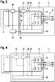
- Fig. 3 is a block diagram of a second embodiment of an electric machine 1, which differs from the one being depicted in fig. 1 , in that the controller 22 of the inverter 9 comprises an output port 30 connectable to a vehicle control unit 31.
- the controller 22 is configured to provide an output signal to the output port 30 when triggering the interrupt device 13 to interrupt the current flow along the line 15.
- a further interrupt device 32 such as a contactor, is connected in series and controllable by the vehicle control unit 31.
- the vehicle control unit 31 Upon receiving the control signal provided by the control unit 22 the vehicle control unit 31 causes the external interrupt device 32 to interrupt the power transmission from the output terminal 11 to the battery 2.
- Fig. 4 is a block diagram of a third embodiment of an electric machine 1, which differs from the one being depicted in fig. 1 , in that the inverter 9 comprises a second interrupt device 13' in addition to the first interrupt device 13.
- the interrupt devices 13, 13' are connected in series and configured to interrupt the power transmission from the output terminal 11 to the input terminal 10 along the same line 15 when being triggered commonly by the control unit 22.
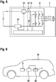
- Fig. 5 is a block diagram of a fourth embodiment of an electric machine 1, which differs from the one being depicted in fig. 4 , in that the second interrupt device 13' is arranged in the line 17 at the low potential of the DC link 12 instead of being connected to the line 15 at the high potential of the DC link 12.
- the active short circuit mode is realized by a switching configuration in which the switching elements 18 connected to the high potential of the DC link 12 are in the blocking state and the switching elements 19 connected to the low potential of the DC link 12 are in the conducting switching state.
- Fig. 6 is a schematic drawing of an embodiment of a vehicle 33, comprising an electric machine 1 according to one of the afore-mentioned embodiments and the battery 2.
- the battery 2 may be connected to the electric machine 1 via the vehicle's interrupt device 32, which may be controllable by the controller 22 of the electric machine 1.
Landscapes
- Engineering & Computer Science (AREA)
- Power Engineering (AREA)
- Transportation (AREA)
- Mechanical Engineering (AREA)
- Life Sciences & Earth Sciences (AREA)
- Sustainable Development (AREA)
- Sustainable Energy (AREA)
- Inverter Devices (AREA)
Abstract
Description
- The invention relates to an inverter for an electric machine, comprising an input terminal connectable to a DC voltage, a DC link connected to the input terminal, an output terminal connectable to stator windings of the electric machine and a controller configured to provide in a pulsing mode pulsing signals causing the inverter to convert the DC voltage into a multiphase AC output voltage at the output terminal and to transfer the inverter from the pulsing mode into an active short circuit mode.
- Aside, the invention relates to an electric machine for a vehicle, a vehicle and method for operating an inverter.
- Inverters are widely known for converting a DC voltage supplied to a DC link via an input terminal into a multiphase AC output voltage. Particularly with respect to automotive applications, such as battery electric vehicles (BEV) or hybrid electric vehicles, the inverter has to be transferred into a safe mode if a failure is detected or an external signal is received. It has been proposed to use a safe pulse off mode (SPO) as the safe mode realized by switching all switching elements being interconnected to a half bridge for each phase and having a diode connected in parallel into a blocking switching state. Thus, the switching elements work as a rectifier built from the diodes. As at high rates of rotation the electromagnetic force of the stator windings may be higher than the DC voltage, a current may flow from an output terminal via the DC link to the input terminal causing a perceptible braking torque. The braking torque may exceed a tolerable level with respect to automotive functional safety.
- To avoid the braking torques, it has been proposed to use an active short circuit (ASC) as safe mode. Therein, the switching elements are in a switching configuration, in which the switching elements connected to a high potential of the DC link are in a conducting state and switching elements connected to a low potential of the DC link are in the blocking state or vice versa.
- However, an active short circuit mode requires to hold the switching configuration with a certain integrity. If it is not possible to hold the switching configuration, e.g. due to a damage of a switching element, both switching elements of one or more half bridges may be in the blocking switching state. As such a switching configuration allows a current flow from the output terminal to the input terminal, the braking torques may occur although an active short circuit mode should be adopted.
- Thus, it is an object of the present invention to provide a more robust inverter, particularly with respect to automotive safety requirements.
- According to the invention, this object is solved by an inverter as initially described, wherein the controller is configured to control at least one interrupt device being arranged in a line of the DC link to interrupt a current flow along the line transmitting power from the output terminal to the input terminal if the inverter is transferred from the pulsing mode into the active short circuit mode.
- The invention is based upon the consideration to avoid the power transmission from the output terminal to the DC link by the interrupt device. The current flow results from an electromagnetic force (e.m.f.), i. e. voltages induced into stator windings connected to the output terminal, being higher than the voltage supplied to the DC link. If the active short circuit mode is adopted successfully, the current flow will be short-circuited inside the inverter. If the active short circuit mode is not adopted successfully the current flow is interrupted by the interrupt device. In other words, the interrupt device provides an addition actuator path in additional to transferring the switching elements to the active short circuit mode for avoiding the undesired braking torques.
- Advantageously, by interrupting the current flow braking torques of the electric machine are avoided effectively. The inverter according to the invention may thus be operated robustly even in the case of an unsuccessful transfer from the pulsing mode into the active short circuit mode. Particularly with respect to automotive applications, the level of functional safety of a vehicle driven by the electric machine is improved.
- With respect to a failure modes, effects, and diagnostic analysis (FMEDA), the interrupt device and a controller function of transferring the inverter to the active short circuit mode may be realized with the same automotive security integrity level (ASIL), e.g. ASIL D. Therefore, the interrupt device may be designed such that it realizes a predefined failure in time (FIT) rate. Preferably, the inverter, including the at least one interrupt device, is formed as a single unit mountable and/or connectable to the stator windings and/or a battery supplying the DC voltage.
- Typically, the inverter comprises a plurality of switching elements being interconnected to a half bridge for each phase of the AC output voltage, wherein the controller is configured to control the switching elements to adopt a switching configuration, in which switching elements connected to a high potential of the DC link are in a conducting switching state and switching elements connected to a low potential of the DC link are in a blocking switching state or vice versa, for transferring the inverter to the active short circuit mode. Preferably, the switching elements are voltage-controlled semiconductor switching elements. The switching elements may comprise a transistor structure, such as insulated gate bipolar transistors (IGBT), insulated gate field-effect transistors, particularly metal oxide semiconductor field-effect transistors (MOSFET), or junction field-effect transistors (JFET). Each switching element may comprise a diode allowing a current flow from the low potential to the high potential and being connected in parallel to the transistor structure. If a switching element fails to be switched into the conducting switching state, both switching elements of the respective half bridge are in the blocking switching state. Then the diodes allow the power transmission from the output terminal to the input terminal. Advantageously, the inverter allows an interrupt of this current flow by using the interrupt device.
- With respect to the inverter according to the invention it is preferred that the interrupt device comprises a switching element with a switching path arranged in the line. The switching element of the interrupt device may be denominated or considered as second switching element in order to distinguish it from the first switching elements being interconnected to the half bridges.
- Preferably, the switching element may comprise a transistor structure providing the switching path. The transistor structure may be an insulated gate bipolar transistor (IGBT) structure, an insulated gate field-effect transistor, particularly metal oxide semiconductor field-effect transistor (MOSFET) structure, or a junction field-effect transistor (JFET) structure. The interrupt device may also comprise a driver element connected in series to a control terminal, such as a gate terminal, of the switching element. The driver unit may be configured to amplify a control signal provided by the controller causing the switching element to be switched to a conducting switching state in the pulsing mode and to be switched to a blocking switching state for interrupting the line.
- Furthermore, the interrupt device may comprise a diode connected in parallel to a switching path of the switching path and allowing a power transmission from the input terminal to the output terminal. The diode may be used as a freewheeling diode, advantageously.
- Alternatively or additionally, the interrupt device may comprise an overvoltage protection element configured to convert a power transmitted from the input terminal into the direction of the output terminal into heat. Particularly, the overvoltage protection element converts the transmitted power to heat when the interrupt device interrupts the power transmission from the output terminal to the input terminal. Advantageously, the overvoltage protection element suppresses the current flow induced externally by line inductances. The overvoltage protection element may comprise a varistor and/or a snubber. The overvoltage protection element may be connected to an output-terminal-side terminal of the switching path and/or to the control terminal of the switching element.
- Preferably, the interrupt device is connected between the input terminal and a smoothing capacitor forming the DC link. Such a circuitry allows the smoothing capacitor to be connected as near as possible to the first switching elements.
- Again with respect to FMEDA considerations, it may be difficult to ensure a certain failure in time rate for a damage of a first switching element. Particularly, a damage of a first switching element may affect other first switching elements resulting in a cascading failure. It may thus be assumed only that a concurrent failure of the function of transferring the inverter to the active short circuit mode and the function of the interrupt device is unlikely. This may render a decomposition of the ASIL of the function of transferring the inverter to the active short circuit state with e.g. ASIL B(D) and the ASIL of the interrupt device with e.g. ASIL B(D) resulting in an overall ASIL D difficult. Thus, the function of transferring the inverter to the active short circuit mode and the function may be both realized with e.g. ASIL D. This may be of high effort since checking for latent faults is difficult while operating the inverter in the pulsing mode. Particularly, it may be necessary to check if the current may be interrupted by the interrupt device while a vehicle is driven. In the following, measures for avoiding these difficulties by providing additional redundancy for interrupting the current are suggested. Therein, a suitable measure for a specific application may be chosen considering different common cause failure scenarios.
- With respect to the inverter according to the invention, the controller may be configured to provide a control signal at an output port when triggering the interrupt device. The output signal may be provided to a vehicle control unit being capable to interrupt a connection between a battery of the vehicle and the input terminal. The connection may be interrupted by a vehicle's interrupt device, e.g. a contactor, assigned to the battery. Advantageously, providing the control signal is realized with low effort as the interrupt device is usually provided to the vehicle for disconnecting the battery from an electrical system of the vehicle. At most, it may be necessary to adjust the capability of the vehicle's interrupt device to switch the currents resulting from the electromagnetic force. However, this adjustment has to be performed only once when designing the vehicle.
- Alternatively or additionally, two interrupt devices are provided to the inverter according to the invention.
- According to a first alternative, the interrupt devices are arranged in series in the same line. With respect to a second alternative, one interrupt device is arranged in a line at a high potential of the DC link and one interrupt device is arranged in a line at a low potential of the DC link.
- With respect to the inverter according to the invention, it is furthermore preferred, that a current measurement device is arranged in the or a line and configured to measure a current flowing through the line, wherein the controller is configured to control the at least one interrupt device to interrupt the line under the additional condition that the measured current reaches and/or exceeds a predefined threshold value. The current is typically representative for the magnitude of the braking torque. Advantageously, this embodiment allows to interrupt the line only if the braking torque exceeds a predefined magnitude, which may be chosen such that less perceptible and/or tolerable braking torques with respect to functional safety requirements do not trigger the interrupt device. The current measurement device may be connected to the output-terminal-side of the interrupt device.
- Furthermore, the above-mentioned object is solved by an electric machine for a vehicle, comprising the inventive inverter and stator windings connected to the output terminal. Preferably, the electric machine is a permanent-magnet synchronous machine.
- Aside, the above-mentioned object is solved by a vehicle, comprising the inventive electric machine configured to drive the vehicle.
- Finally, the above-mentioned object is solved by a method for operating an inverter for an electric machine, comprising an input terminal connectable to a DC voltage, a DC link connected to the input terminal and an output terminal connectable to stator windings of the electric machine, wherein in a pulsing mode pulsing signals causing the inverter to convert the DC voltage into a multiphase AC output voltage at the output terminal are provided and the inverter is transferred from the pulsing mode into an active short circuit mode, wherein at least one interrupt device being arranged in a line of the DC link interrupts a current flow along the line transmitting a power from the output terminal to the input terminal if the inverter is transferred from the pulsing mode into the active short circuit mode.
- All statements referring to the inverter according to the invention refer to the electric machine, the vehicle and method as well, so that advantages of the inverter may be achieved by the electric machine, the vehicle and the method, too.
- Further details and advantages are described in the following with reference to the schematic drawings, which show:
- Fig. 1
- a block diagram of a first embodiment of an electric machine according to the invention;
- Fig. 2
- a block diagram of an interrupt device of the electric machine depicted in
fig. 1 ; - Fig. 3
- a block diagram of a second embodiment of an electric machine according to the invention;
- Fig. 4
- a block diagram of a third embodiment of an electric machine according to the invention;
- Fig. 5
- a block diagram of a fourth embodiment of an electric machine according to the invention; and
- Fig. 6
- a schematic diagram of an embodiment of a vehicle according to the invention.
-
Fig. 1 is a block diagram of a first embodiment of anelectric machine 1 connected to abattery 2, represented by avoltage source 3 and an internal resistance 4. Preferably, theelectric machine 1 is a permanent-magnet synchronous machine. - The
electric machine 1 comprises three stator windings 5 each represented by a resistor 6, an inductance 7 and avoltage source 8 corresponding to an electromagnetic force (e.m.f.) induced by a rotor (not shown). Furthermore, theelectric machine 1 comprises aninverter 9 with aninput terminal 10 connected to thebattery 2 and with anoutput terminal 11 connected to the stator windings 5. - Inside the inverter 9 a
DC link 12 is connected to theinput terminal 10, comprising an interruptdevice 13 and acurrent measurement device 14 both arranged in aline 15 at a high potential of theDC link 12 and connected in series to each other. The DC link 12 is formed by a smoothingcapacitor 16, connected between theline 15 and a line 17 at a low potential of theDC link 12. - Additionally, the
inverter 9 comprises three switchingelements 18 connected to the high potential of theDC link 12 and three switchingelements 19 connected to the low potential of theDC link 12, wherein the switchingelements output terminal 11. Each switchingelement transistor structure 20, which is depicted by a switch symbol for reasons of simplicity, and adiode 21. Thediode 21 is connected in parallel to thetransistor structure 20 and allows a power transmission from the low potential to the high potential. Thetransistor structure 20 may be an insulated gate bipolar transistor structure (IGBT), an insulated gate field-effect transistor structure, such as a metal oxide semiconductor field-effect transistor (MOSFET) structure, or a junction fed field-effect transistor (JFET) structure. If the transistor structure is a MOSFET structure, thediode 21 may be an internal parasitic diode. - Moreover, the
inverter 9 comprises acontroller 22, wherein inFig. 1 signal connections from thecontroller 22 are depicted in dashed lines. -
Fig. 2 is a block diagram of the interruptdevice 13 connected in series to thecurrent measurement device 14 along theline 15 and controllable by thecontroller 22. - The interrupt
device 13 comprises a switchingelement 23 with atransistor structure 24, connected in parallel to adiode 25, which allows a power transmission or a current flow, respectively, from theinput terminal 10 to theoutput terminal 11. Thetransistor structure 24 may be an insulated gate bipolar transistor (IGBT) structure, an insulated gate field-effect transistor, such as a metal oxide semiconductor field-effect transistor (MOSFET) structure, or a junction fed field-effect transistor (JFET) structure. The interruptdevice 13 comprises adriver element 26 connected to a control terminal 27, particularly a gate terminal, of thetransistor structure 24 and being controllable by thecontroller 22. Additionally, the interruptdevice 13 comprisesovervoltage protection element 28, such as a varistor or a snubber, connected in parallel to the control terminal 27 and a terminal 29 of a switching path of thetransistor structure 24. - In the pulsing mode of the
inverter 9 thecontroller 22 provides pulsing signals causing theinverter 9 to convert the DC voltage supplied by thebattery 2 to theinput terminal 10 into a multiphase AC output voltage at theoutput terminal 11 for the stator windings 5. Thecontroller 22 provides the pulsing signals such that the switchingelements - In the pulsing mode the switching
element 23 of the interruptdevice 13 is in the conducting switching state. - In the case of a failure or upon receiving an external signal, the
controller 22 transfers theinverter 9 from the pulsing mode into an active short circuit mode. The active short circuit mode is a switching configuration of the switchingelements switching elements 18 connected to the high potential are in the blocking state and theswitching elements 19 are in the conducting state. By this switching configuration, the stator windings 5 are short-circuited inside theinverter 9. - However, in the case of a failure or damage of one or more of the switching
elements 18 the conducting switching state may not be adopted or may be left after having been adopted. The stator winding 5 connected to the half bridge, in which both switchingelements diodes 21 of the switchingelements output terminal 11, theDC link 12, theinput terminal 10 to thebattery 2. Such a power transmission results from thevoltage source 8, if the electromagnetic force is higher than the DC voltage of thebattery 2 and may cause high breaking torques which may not be tolerated due to safety requirements. - Thus, the
current measurement device 14 monitors the current flow from theoutput terminal 11 to theinput terminal 10 along theline 15 and feeds measuring signals to thecontroller 22. If the current flow reaches or exceeds a predefined threshold value, thecontroller 22 provides a control signal to the interruptdevice 13, particularly to thedriver element 26, which switches the switchingelement 23 into a blocking switching state. Thus, the power transmission from theoutput terminal 11 to theDC link 12 is interrupted and high breaking torques are avoided. - After switching the switching
element 23 to the blocking state, a power or a current flow, respectively, from thebattery 2 via theinput terminal 10 into the direction of theDC link 12 may be induced by line inductivities between thebattery 2 and theinverter 9. This transmitted power is converted into heat by theovervoltage protection element 28. -
Fig. 3 is a block diagram of a second embodiment of anelectric machine 1, which differs from the one being depicted infig. 1 , in that thecontroller 22 of theinverter 9 comprises anoutput port 30 connectable to avehicle control unit 31. Thecontroller 22 is configured to provide an output signal to theoutput port 30 when triggering the interruptdevice 13 to interrupt the current flow along theline 15. - Between the
battery 2 and the input terminal 10 a further interruptdevice 32, such as a contactor, is connected in series and controllable by thevehicle control unit 31. Upon receiving the control signal provided by thecontrol unit 22 thevehicle control unit 31 causes the external interruptdevice 32 to interrupt the power transmission from theoutput terminal 11 to thebattery 2. -
Fig. 4 is a block diagram of a third embodiment of anelectric machine 1, which differs from the one being depicted infig. 1 , in that theinverter 9 comprises a second interrupt device 13' in addition to the first interruptdevice 13. The interruptdevices 13, 13' are connected in series and configured to interrupt the power transmission from theoutput terminal 11 to theinput terminal 10 along thesame line 15 when being triggered commonly by thecontrol unit 22. -
Fig. 5 is a block diagram of a fourth embodiment of anelectric machine 1, which differs from the one being depicted infig. 4 , in that the second interrupt device 13' is arranged in the line 17 at the low potential of theDC link 12 instead of being connected to theline 15 at the high potential of theDC link 12. - According to a further embodiment corresponding to the afore-mentioned ones, the active short circuit mode is realized by a switching configuration in which the
switching elements 18 connected to the high potential of theDC link 12 are in the blocking state and theswitching elements 19 connected to the low potential of theDC link 12 are in the conducting switching state. -
Fig. 6 is a schematic drawing of an embodiment of avehicle 33, comprising anelectric machine 1 according to one of the afore-mentioned embodiments and thebattery 2. Thebattery 2 may be connected to theelectric machine 1 via the vehicle's interruptdevice 32, which may be controllable by thecontroller 22 of theelectric machine 1.
Claims (15)
- Inverter (9) for an electric machine (1), comprising an input terminal (10) connectable to a DC voltage, a DC link (12) connected to the input terminal (10), an output terminal (11) connectable to stator windings (5) of the electric machine (1) and a controller (22) configured to provide in a pulsing mode pulsing signals causing the inverter (9) to convert the DC voltage into a multiphase AC output voltage at the output terminal (11) and to transfer the inverter (9) from the pulsing mode into an active short circuit mode, characterized in that the controller (22) is configured to control at least one interrupt device (13, 13') being arranged in a line (15, 17) of the DC link (12) to interrupt a current flow along the line (15, 17) transmitting a power from the output terminal (11) to the input terminal (10) if the inverter (9) is transferred from the pulsing mode into the active short circuit mode.
- Inverter (9) according to claim 1, characterized in that inverter (9) comprises a plurality of switching elements (18, 19) being interconnected to a half bridge for each phase of the AC output voltage, wherein the controller (22) is configured to control the switching elements (18, 19) to adopt a switching configuration, in which switching elements (18) connected to a high potential of the DC link (12) are in a conducting switching state and switching elements (19) connected to a low potential of the DC link (12) are in a blocking switching state or vice versa, for transferring the inverter (9) to the active short circuit mode.
- Inverter (9) according to claim 1 or 2, characterized in that the interrupt device (13, 13') comprises a switching element (23) with a switching path arranged in the line (15, 17).
- Inverter (9) according to claim 3, characterized in that the switching element (23) comprises a transistor structure (24) providing the switching path.
- Inverter (9) according to claim 3 or 4, characterized in that the interrupt device (13, 13') comprises a diode (25) connected in parallel to the switching path and allowing a power transmission from the input terminal (10) to the output terminal (11).
- Inverter (9) according to any of the preceding claims, characterized in that the interrupt device (13, 13') comprises an overvoltage protection element (28) configured to convert a power transmitted from the input terminal (10) into the direction of the output terminal (11) into heat.
- Inverter (9) according to any of the preceding claims, characterized in that the interrupt device (13, 13') is connected between the input terminal (10) and a smoothing capacitor (16) of the DC link (12).
- Inverter (9) according to any of the preceding claims, characterized in that the controller (22) is configured to provide a control signal at an output port (30), when triggering the interrupt device (13, 13').
- Inverter (9) according to any of the preceding claims, characterized in that two interrupt devices (13, 13') are provided.
- Inverter (9) according to claim 9, characterized in that the interrupt devices (13, 13') are arranged in series in the same line.
- Inverter (9) according to claim 9, characterized in that one interrupt device (13) is arranged in a line (15) at a high potential of the DC link (12) and one interrupt device (13') is arranged in a line (17) at a low potential of the DC link (12).
- Inverter (9) according to any of the preceding claims, characterized in that a current measurement device (14) is arranged in the or a line (15, 17) and configured to measure a current flowing through the line (15, 17), wherein the controller (22) is configured to control the at least one interrupt device (13, 13') to interrupt the line (15, 17) under the additional condition that the measured current reaches and/or exceeds a predefined threshold value.
- Electric machine (1) for a vehicle (33), comprising an inverter (9) according to any of claims 1 to 12 and stator windings (5) connected to the output terminal (11).
- Vehicle (33), comprising an electric machine (1) according to claim 13 configured to drive the vehicle (33).
- Method for operating an inverter (9) for an electric machine (1), comprising an input terminal (10) connectable to a DC voltage, a DC link (12) connected to the input terminal (10) and an output terminal (11) connectable to stator windings (5) of the electric machine (1), wherein in a pulsing mode pulsing signals causing the inverter (9) to convert the DC voltage into a multiphase AC output voltage at the output terminal (11) are provided and the inverter (9) is transferred from the pulsing mode into an active short circuit mode, wherein at least one interrupt device (13, 13') being arranged in a line (15, 17) of the DC link (12) interrupts a current flow along the line (15, 17) transmitting a power from the output terminal (11) to the input terminal (10) if the inverter (9) is transferred from the pulsing mode into the active short circuit mode.
Priority Applications (1)
| Application Number | Priority Date | Filing Date | Title |
|---|---|---|---|
| EP17196910.8A EP3473483B1 (en) | 2017-10-17 | 2017-10-17 | Inverter for an electric machine, electric machine for a vehicle, vehicle and method for operating an inverter |
Applications Claiming Priority (1)
| Application Number | Priority Date | Filing Date | Title |
|---|---|---|---|
| EP17196910.8A EP3473483B1 (en) | 2017-10-17 | 2017-10-17 | Inverter for an electric machine, electric machine for a vehicle, vehicle and method for operating an inverter |
Publications (2)
| Publication Number | Publication Date |
|---|---|
| EP3473483A1 true EP3473483A1 (en) | 2019-04-24 |
| EP3473483B1 EP3473483B1 (en) | 2022-11-02 |
Family
ID=60138251
Family Applications (1)
| Application Number | Title | Priority Date | Filing Date |
|---|---|---|---|
| EP17196910.8A Active EP3473483B1 (en) | 2017-10-17 | 2017-10-17 | Inverter for an electric machine, electric machine for a vehicle, vehicle and method for operating an inverter |
Country Status (1)
| Country | Link |
|---|---|
| EP (1) | EP3473483B1 (en) |
Cited By (2)
| Publication number | Priority date | Publication date | Assignee | Title |
|---|---|---|---|---|
| CN114285001A (en) * | 2021-12-31 | 2022-04-05 | 蜂巢传动科技河北有限公司 | Vehicle motor control system and method |
| CN114421427A (en) * | 2021-12-17 | 2022-04-29 | 广东美的白色家电技术创新中心有限公司 | Control method, motor controller, storage medium and equipment |
Families Citing this family (1)
| Publication number | Priority date | Publication date | Assignee | Title |
|---|---|---|---|---|
| CN120840415A (en) * | 2024-04-26 | 2025-10-28 | 华为数字能源技术有限公司 | Motor Controllers, Distributed Powertrains, and Vehicles |
Citations (7)
| Publication number | Priority date | Publication date | Assignee | Title |
|---|---|---|---|---|
| EP2573928A1 (en) * | 2011-09-26 | 2013-03-27 | Brusa Elektronik AG | Overcurrent protection and reverse current blocking in an indirect inverter for operating an alternating current machine |
| US20130181645A1 (en) * | 2011-07-18 | 2013-07-18 | Siemens Aktiengesellschaft | Drive system and method for operating such a drive system |
| DE102012101508A1 (en) * | 2012-02-24 | 2013-08-29 | Volkswagen Aktiengesellschaft | Method for operating e.g. permanently excited synchronous machine for motor car, involves comparing voltage in intermediate circuit with minimum limit voltage value in circuit, to open converter valves so as to drive machine |
| US20140009096A1 (en) * | 2011-03-10 | 2014-01-09 | Mitsubishi Electric Corporation | Power conversion device |
| DE102013016960A1 (en) * | 2013-10-11 | 2014-07-24 | Daimler Ag | Inverter unit for electric machine has control device to control inverter switches and bridge switches to close, and to cause free-wheel to control one of bridge switches and other inverter switches to open in response to error signal |
| DE102016207254A1 (en) * | 2015-10-14 | 2017-04-20 | Continental Automotive Gmbh | Inverter, electric drive arrangement with an inverter |
| JP2017184393A (en) * | 2016-03-29 | 2017-10-05 | アイシン・エィ・ダブリュ株式会社 | Inverter controller |
-
2017
- 2017-10-17 EP EP17196910.8A patent/EP3473483B1/en active Active
Patent Citations (7)
| Publication number | Priority date | Publication date | Assignee | Title |
|---|---|---|---|---|
| US20140009096A1 (en) * | 2011-03-10 | 2014-01-09 | Mitsubishi Electric Corporation | Power conversion device |
| US20130181645A1 (en) * | 2011-07-18 | 2013-07-18 | Siemens Aktiengesellschaft | Drive system and method for operating such a drive system |
| EP2573928A1 (en) * | 2011-09-26 | 2013-03-27 | Brusa Elektronik AG | Overcurrent protection and reverse current blocking in an indirect inverter for operating an alternating current machine |
| DE102012101508A1 (en) * | 2012-02-24 | 2013-08-29 | Volkswagen Aktiengesellschaft | Method for operating e.g. permanently excited synchronous machine for motor car, involves comparing voltage in intermediate circuit with minimum limit voltage value in circuit, to open converter valves so as to drive machine |
| DE102013016960A1 (en) * | 2013-10-11 | 2014-07-24 | Daimler Ag | Inverter unit for electric machine has control device to control inverter switches and bridge switches to close, and to cause free-wheel to control one of bridge switches and other inverter switches to open in response to error signal |
| DE102016207254A1 (en) * | 2015-10-14 | 2017-04-20 | Continental Automotive Gmbh | Inverter, electric drive arrangement with an inverter |
| JP2017184393A (en) * | 2016-03-29 | 2017-10-05 | アイシン・エィ・ダブリュ株式会社 | Inverter controller |
Cited By (4)
| Publication number | Priority date | Publication date | Assignee | Title |
|---|---|---|---|---|
| CN114421427A (en) * | 2021-12-17 | 2022-04-29 | 广东美的白色家电技术创新中心有限公司 | Control method, motor controller, storage medium and equipment |
| CN114421427B (en) * | 2021-12-17 | 2024-03-26 | 广东美的白色家电技术创新中心有限公司 | Control method, motor controller, storage medium and equipment |
| CN114285001A (en) * | 2021-12-31 | 2022-04-05 | 蜂巢传动科技河北有限公司 | Vehicle motor control system and method |
| CN114285001B (en) * | 2021-12-31 | 2024-01-26 | 蜂巢传动科技河北有限公司 | Vehicle motor control system and method |
Also Published As
| Publication number | Publication date |
|---|---|
| EP3473483B1 (en) | 2022-11-02 |
Similar Documents
| Publication | Publication Date | Title |
|---|---|---|
| US9154051B2 (en) | Operating state circuit for an inverter and method for setting operating states of an inverter | |
| US10998808B2 (en) | Power conversion device | |
| CN104170238B (en) | Convertor device and power steering gear | |
| US8269450B2 (en) | Winding switching apparatus and winding switching system | |
| CN109075564B (en) | System for actively short-circuiting phases of an inverter and a motor vehicle drive | |
| JP2019071772A (en) | Inverter for electric vehicle | |
| US9242564B2 (en) | Converter for an electrical machine, controller and method for operating a converter | |
| CN111656666B (en) | power conversion device | |
| JP2015032984A (en) | Device for driving semiconductor element, and power conversion device using the same | |
| US20190020263A1 (en) | Power conversion device | |
| WO2012120567A1 (en) | Power conversion device | |
| EP3473483B1 (en) | Inverter for an electric machine, electric machine for a vehicle, vehicle and method for operating an inverter | |
| US20120217918A1 (en) | Inverter | |
| CN110311619A (en) | A motor control circuit and electric vehicle | |
| US20120229068A1 (en) | Inverter | |
| US20250058652A1 (en) | Drive Apparatus and Electric Vehicle | |
| CN111264024B (en) | Inverter device, control circuit thereof, and motor drive system | |
| EP4378740A1 (en) | Electric vehicle control system and electric vehicle | |
| US8760890B2 (en) | Current source inverter | |
| JP2022515397A (en) | System for controlling voltage transducers | |
| CN115280662B (en) | Control circuit of power converter | |
| JP7322653B2 (en) | switch drive | |
| US12603596B2 (en) | Power supply circuit in an inverter for driving an electrical machine, method of operating the power supply circuit and safety control device | |
| US20250007437A1 (en) | Inverter for controlling an electrical machine, method of operating the inverter and safety control device | |
| JP7460508B2 (en) | Power Conversion Equipment |
Legal Events
| Date | Code | Title | Description |
|---|---|---|---|
| PUAI | Public reference made under article 153(3) epc to a published international application that has entered the european phase |
Free format text: ORIGINAL CODE: 0009012 |
|
| STAA | Information on the status of an ep patent application or granted ep patent |
Free format text: STATUS: THE APPLICATION HAS BEEN PUBLISHED |
|
| AK | Designated contracting states |
Kind code of ref document: A1 Designated state(s): AL AT BE BG CH CY CZ DE DK EE ES FI FR GB GR HR HU IE IS IT LI LT LU LV MC MK MT NL NO PL PT RO RS SE SI SK SM TR |
|
| AX | Request for extension of the european patent |
Extension state: BA ME |
|
| STAA | Information on the status of an ep patent application or granted ep patent |
Free format text: STATUS: REQUEST FOR EXAMINATION WAS MADE |
|
| 17P | Request for examination filed |
Effective date: 20191021 |
|
| RBV | Designated contracting states (corrected) |
Designated state(s): AL AT BE BG CH CY CZ DE DK EE ES FI FR GB GR HR HU IE IS IT LI LT LU LV MC MK MT NL NO PL PT RO RS SE SI SK SM TR |
|
| STAA | Information on the status of an ep patent application or granted ep patent |
Free format text: STATUS: EXAMINATION IS IN PROGRESS |
|
| 17Q | First examination report despatched |
Effective date: 20200615 |
|
| REG | Reference to a national code |
Ref country code: DE Ref legal event code: R079 Ref document number: 602017063219 Country of ref document: DE Free format text: PREVIOUS MAIN CLASS: B60L0003000000 Ipc: H02H0003050000 |
|
| GRAP | Despatch of communication of intention to grant a patent |
Free format text: ORIGINAL CODE: EPIDOSNIGR1 |
|
| STAA | Information on the status of an ep patent application or granted ep patent |
Free format text: STATUS: GRANT OF PATENT IS INTENDED |
|
| RIC1 | Information provided on ipc code assigned before grant |
Ipc: B60L 3/04 20060101ALI20211004BHEP Ipc: B60L 15/00 20060101ALI20211004BHEP Ipc: H02P 3/18 20060101ALI20211004BHEP Ipc: H02H 7/122 20060101ALI20211004BHEP Ipc: H02P 3/22 20060101ALI20211004BHEP Ipc: B60L 3/00 20190101ALI20211004BHEP Ipc: H02H 3/05 20060101AFI20211004BHEP |
|
| INTG | Intention to grant announced |
Effective date: 20211028 |
|
| GRAJ | Information related to disapproval of communication of intention to grant by the applicant or resumption of examination proceedings by the epo deleted |
Free format text: ORIGINAL CODE: EPIDOSDIGR1 |
|
| STAA | Information on the status of an ep patent application or granted ep patent |
Free format text: STATUS: EXAMINATION IS IN PROGRESS |
|
| GRAP | Despatch of communication of intention to grant a patent |
Free format text: ORIGINAL CODE: EPIDOSNIGR1 |
|
| STAA | Information on the status of an ep patent application or granted ep patent |
Free format text: STATUS: GRANT OF PATENT IS INTENDED |
|
| INTC | Intention to grant announced (deleted) | ||
| INTG | Intention to grant announced |
Effective date: 20220330 |
|
| GRAS | Grant fee paid |
Free format text: ORIGINAL CODE: EPIDOSNIGR3 |
|
| RAP3 | Party data changed (applicant data changed or rights of an application transferred) |
Owner name: VALEO EAUTOMOTIVE GERMANY GMBH |
|
| GRAA | (expected) grant |
Free format text: ORIGINAL CODE: 0009210 |
|
| STAA | Information on the status of an ep patent application or granted ep patent |
Free format text: STATUS: THE PATENT HAS BEEN GRANTED |
|
| AK | Designated contracting states |
Kind code of ref document: B1 Designated state(s): AL AT BE BG CH CY CZ DE DK EE ES FI FR GB GR HR HU IE IS IT LI LT LU LV MC MK MT NL NO PL PT RO RS SE SI SK SM TR |
|
| REG | Reference to a national code |
Ref country code: GB Ref legal event code: FG4D |
|
| REG | Reference to a national code |
Ref country code: CH Ref legal event code: EP Ref country code: AT Ref legal event code: REF Ref document number: 1529470 Country of ref document: AT Kind code of ref document: T Effective date: 20221115 |
|
| REG | Reference to a national code |
Ref country code: DE Ref legal event code: R096 Ref document number: 602017063219 Country of ref document: DE |
|
| REG | Reference to a national code |
Ref country code: IE Ref legal event code: FG4D |
|
| REG | Reference to a national code |
Ref country code: LT Ref legal event code: MG9D |
|
| REG | Reference to a national code |
Ref country code: NL Ref legal event code: MP Effective date: 20221102 |
|
| REG | Reference to a national code |
Ref country code: AT Ref legal event code: MK05 Ref document number: 1529470 Country of ref document: AT Kind code of ref document: T Effective date: 20221102 |
|
| PG25 | Lapsed in a contracting state [announced via postgrant information from national office to epo] |
Ref country code: SE Free format text: LAPSE BECAUSE OF FAILURE TO SUBMIT A TRANSLATION OF THE DESCRIPTION OR TO PAY THE FEE WITHIN THE PRESCRIBED TIME-LIMIT Effective date: 20221102 Ref country code: PT Free format text: LAPSE BECAUSE OF FAILURE TO SUBMIT A TRANSLATION OF THE DESCRIPTION OR TO PAY THE FEE WITHIN THE PRESCRIBED TIME-LIMIT Effective date: 20230302 Ref country code: NO Free format text: LAPSE BECAUSE OF FAILURE TO SUBMIT A TRANSLATION OF THE DESCRIPTION OR TO PAY THE FEE WITHIN THE PRESCRIBED TIME-LIMIT Effective date: 20230202 Ref country code: LT Free format text: LAPSE BECAUSE OF FAILURE TO SUBMIT A TRANSLATION OF THE DESCRIPTION OR TO PAY THE FEE WITHIN THE PRESCRIBED TIME-LIMIT Effective date: 20221102 Ref country code: FI Free format text: LAPSE BECAUSE OF FAILURE TO SUBMIT A TRANSLATION OF THE DESCRIPTION OR TO PAY THE FEE WITHIN THE PRESCRIBED TIME-LIMIT Effective date: 20221102 Ref country code: ES Free format text: LAPSE BECAUSE OF FAILURE TO SUBMIT A TRANSLATION OF THE DESCRIPTION OR TO PAY THE FEE WITHIN THE PRESCRIBED TIME-LIMIT Effective date: 20221102 Ref country code: AT Free format text: LAPSE BECAUSE OF FAILURE TO SUBMIT A TRANSLATION OF THE DESCRIPTION OR TO PAY THE FEE WITHIN THE PRESCRIBED TIME-LIMIT Effective date: 20221102 |
|
| PG25 | Lapsed in a contracting state [announced via postgrant information from national office to epo] |
Ref country code: RS Free format text: LAPSE BECAUSE OF FAILURE TO SUBMIT A TRANSLATION OF THE DESCRIPTION OR TO PAY THE FEE WITHIN THE PRESCRIBED TIME-LIMIT Effective date: 20221102 Ref country code: PL Free format text: LAPSE BECAUSE OF FAILURE TO SUBMIT A TRANSLATION OF THE DESCRIPTION OR TO PAY THE FEE WITHIN THE PRESCRIBED TIME-LIMIT Effective date: 20221102 Ref country code: LV Free format text: LAPSE BECAUSE OF FAILURE TO SUBMIT A TRANSLATION OF THE DESCRIPTION OR TO PAY THE FEE WITHIN THE PRESCRIBED TIME-LIMIT Effective date: 20221102 Ref country code: IS Free format text: LAPSE BECAUSE OF FAILURE TO SUBMIT A TRANSLATION OF THE DESCRIPTION OR TO PAY THE FEE WITHIN THE PRESCRIBED TIME-LIMIT Effective date: 20230302 Ref country code: HR Free format text: LAPSE BECAUSE OF FAILURE TO SUBMIT A TRANSLATION OF THE DESCRIPTION OR TO PAY THE FEE WITHIN THE PRESCRIBED TIME-LIMIT Effective date: 20221102 Ref country code: GR Free format text: LAPSE BECAUSE OF FAILURE TO SUBMIT A TRANSLATION OF THE DESCRIPTION OR TO PAY THE FEE WITHIN THE PRESCRIBED TIME-LIMIT Effective date: 20230203 |
|
| PG25 | Lapsed in a contracting state [announced via postgrant information from national office to epo] |
Ref country code: NL Free format text: LAPSE BECAUSE OF FAILURE TO SUBMIT A TRANSLATION OF THE DESCRIPTION OR TO PAY THE FEE WITHIN THE PRESCRIBED TIME-LIMIT Effective date: 20221102 |
|
| P01 | Opt-out of the competence of the unified patent court (upc) registered |
Effective date: 20230528 |
|
| PG25 | Lapsed in a contracting state [announced via postgrant information from national office to epo] |
Ref country code: SM Free format text: LAPSE BECAUSE OF FAILURE TO SUBMIT A TRANSLATION OF THE DESCRIPTION OR TO PAY THE FEE WITHIN THE PRESCRIBED TIME-LIMIT Effective date: 20221102 Ref country code: RO Free format text: LAPSE BECAUSE OF FAILURE TO SUBMIT A TRANSLATION OF THE DESCRIPTION OR TO PAY THE FEE WITHIN THE PRESCRIBED TIME-LIMIT Effective date: 20221102 Ref country code: EE Free format text: LAPSE BECAUSE OF FAILURE TO SUBMIT A TRANSLATION OF THE DESCRIPTION OR TO PAY THE FEE WITHIN THE PRESCRIBED TIME-LIMIT Effective date: 20221102 Ref country code: DK Free format text: LAPSE BECAUSE OF FAILURE TO SUBMIT A TRANSLATION OF THE DESCRIPTION OR TO PAY THE FEE WITHIN THE PRESCRIBED TIME-LIMIT Effective date: 20221102 Ref country code: CZ Free format text: LAPSE BECAUSE OF FAILURE TO SUBMIT A TRANSLATION OF THE DESCRIPTION OR TO PAY THE FEE WITHIN THE PRESCRIBED TIME-LIMIT Effective date: 20221102 |
|
| REG | Reference to a national code |
Ref country code: DE Ref legal event code: R097 Ref document number: 602017063219 Country of ref document: DE |
|
| PG25 | Lapsed in a contracting state [announced via postgrant information from national office to epo] |
Ref country code: SK Free format text: LAPSE BECAUSE OF FAILURE TO SUBMIT A TRANSLATION OF THE DESCRIPTION OR TO PAY THE FEE WITHIN THE PRESCRIBED TIME-LIMIT Effective date: 20221102 Ref country code: AL Free format text: LAPSE BECAUSE OF FAILURE TO SUBMIT A TRANSLATION OF THE DESCRIPTION OR TO PAY THE FEE WITHIN THE PRESCRIBED TIME-LIMIT Effective date: 20221102 |
|
| PLBE | No opposition filed within time limit |
Free format text: ORIGINAL CODE: 0009261 |
|
| STAA | Information on the status of an ep patent application or granted ep patent |
Free format text: STATUS: NO OPPOSITION FILED WITHIN TIME LIMIT |
|
| 26N | No opposition filed |
Effective date: 20230803 |
|
| PG25 | Lapsed in a contracting state [announced via postgrant information from national office to epo] |
Ref country code: SI Free format text: LAPSE BECAUSE OF FAILURE TO SUBMIT A TRANSLATION OF THE DESCRIPTION OR TO PAY THE FEE WITHIN THE PRESCRIBED TIME-LIMIT Effective date: 20221102 |
|
| PG25 | Lapsed in a contracting state [announced via postgrant information from national office to epo] |
Ref country code: IT Free format text: LAPSE BECAUSE OF FAILURE TO SUBMIT A TRANSLATION OF THE DESCRIPTION OR TO PAY THE FEE WITHIN THE PRESCRIBED TIME-LIMIT Effective date: 20221102 Ref country code: MC Free format text: LAPSE BECAUSE OF FAILURE TO SUBMIT A TRANSLATION OF THE DESCRIPTION OR TO PAY THE FEE WITHIN THE PRESCRIBED TIME-LIMIT Effective date: 20221102 |
|
| REG | Reference to a national code |
Ref country code: CH Ref legal event code: PL |
|
| REG | Reference to a national code |
Ref country code: BE Ref legal event code: MM Effective date: 20231031 |
|
| PG25 | Lapsed in a contracting state [announced via postgrant information from national office to epo] |
Ref country code: LU Free format text: LAPSE BECAUSE OF NON-PAYMENT OF DUE FEES Effective date: 20231017 |
|
| PG25 | Lapsed in a contracting state [announced via postgrant information from national office to epo] |
Ref country code: LU Free format text: LAPSE BECAUSE OF NON-PAYMENT OF DUE FEES Effective date: 20231017 |
|
| PG25 | Lapsed in a contracting state [announced via postgrant information from national office to epo] |
Ref country code: CH Free format text: LAPSE BECAUSE OF NON-PAYMENT OF DUE FEES Effective date: 20231031 |
|
| PG25 | Lapsed in a contracting state [announced via postgrant information from national office to epo] |
Ref country code: CH Free format text: LAPSE BECAUSE OF NON-PAYMENT OF DUE FEES Effective date: 20231031 |
|
| PG25 | Lapsed in a contracting state [announced via postgrant information from national office to epo] |
Ref country code: BE Free format text: LAPSE BECAUSE OF NON-PAYMENT OF DUE FEES Effective date: 20231031 |
|
| PG25 | Lapsed in a contracting state [announced via postgrant information from national office to epo] |
Ref country code: IE Free format text: LAPSE BECAUSE OF NON-PAYMENT OF DUE FEES Effective date: 20231017 |
|
| PG25 | Lapsed in a contracting state [announced via postgrant information from national office to epo] |
Ref country code: IE Free format text: LAPSE BECAUSE OF NON-PAYMENT OF DUE FEES Effective date: 20231017 |
|
| PG25 | Lapsed in a contracting state [announced via postgrant information from national office to epo] |
Ref country code: BG Free format text: LAPSE BECAUSE OF FAILURE TO SUBMIT A TRANSLATION OF THE DESCRIPTION OR TO PAY THE FEE WITHIN THE PRESCRIBED TIME-LIMIT Effective date: 20221102 |
|
| PG25 | Lapsed in a contracting state [announced via postgrant information from national office to epo] |
Ref country code: BG Free format text: LAPSE BECAUSE OF FAILURE TO SUBMIT A TRANSLATION OF THE DESCRIPTION OR TO PAY THE FEE WITHIN THE PRESCRIBED TIME-LIMIT Effective date: 20221102 |
|
| PG25 | Lapsed in a contracting state [announced via postgrant information from national office to epo] |
Ref country code: CY Free format text: LAPSE BECAUSE OF FAILURE TO SUBMIT A TRANSLATION OF THE DESCRIPTION OR TO PAY THE FEE WITHIN THE PRESCRIBED TIME-LIMIT; INVALID AB INITIO Effective date: 20171017 |
|
| PG25 | Lapsed in a contracting state [announced via postgrant information from national office to epo] |
Ref country code: HU Free format text: LAPSE BECAUSE OF FAILURE TO SUBMIT A TRANSLATION OF THE DESCRIPTION OR TO PAY THE FEE WITHIN THE PRESCRIBED TIME-LIMIT; INVALID AB INITIO Effective date: 20171017 |
|
| PG25 | Lapsed in a contracting state [announced via postgrant information from national office to epo] |
Ref country code: TR Free format text: LAPSE BECAUSE OF FAILURE TO SUBMIT A TRANSLATION OF THE DESCRIPTION OR TO PAY THE FEE WITHIN THE PRESCRIBED TIME-LIMIT Effective date: 20221102 |
|
| PGFP | Annual fee paid to national office [announced via postgrant information from national office to epo] |
Ref country code: DE Payment date: 20251015 Year of fee payment: 9 |
|
| PGFP | Annual fee paid to national office [announced via postgrant information from national office to epo] |
Ref country code: GB Payment date: 20251023 Year of fee payment: 9 |
|
| PGFP | Annual fee paid to national office [announced via postgrant information from national office to epo] |
Ref country code: FR Payment date: 20251027 Year of fee payment: 9 |